

Page 1

Page 2

ADSL Barricade
TM
4-Port ADSL Router with Built-in
Annex B ADSL Modem
User Guide
February 2004
Page 3

ABLE OF CONTENTS
T
Introduction . . . . . . . . . . . . . . . . . . . . . . . . . . . . . . . 1
Features . . . . . . . . . . . . . . . . . . . . . . . . . . . . . . . . . . . . . . . . . . .1
System Requirements . . . . . . . . . . . . . . . . . . . . . . . . . . . . . . . .2
ADSL Barricade Overview . . . . . . . . . . . . . . . . . . . 3
Package Contents . . . . . . . . . . . . . . . . . . . . . . . . . . . . . . . . . . .3
Front Panel . . . . . . . . . . . . . . . . . . . . . . . . . . . . . . . . . . . . . . . . .4
Rear Panel . . . . . . . . . . . . . . . . . . . . . . . . . . . . . . . . . . . . . . . . .5
Configuration . . . . . . . . . . . . . . . . . . . . . . . . . . . . . 7
Connecting the ADSL Barricade to Your Computer . . . . . . . . . .7
Configuring Your Computers . . . . . . . . . . . . . . . . . . . . . . . . . . .8
Entering the Admin Page . . . . . . . . . . . . . . . . . . . . . . . . . . . . . 16
Status Page . . . . . . . . . . . . . . . . . . . . . . . . . . . . . . . . . .17
WAN Configuration . . . . . . . . . . . . . . . . . . . . . . . . . . . . . 23
LAN Configuration . . . . . . . . . . . . . . . . . . . . . . . . . . . . . 29
PPP Configuration . . . . . . . . . . . . . . . . . . . . . . . . . . . . .30
NAT Configuration . . . . . . . . . . . . . . . . . . . . . . . . . . . . .33
Virtual Server Configuration. . . . . . . . . . . . . . . . . . . . . . .35
DNS Configuration. . . . . . . . . . . . . . . . . . . . . . . . . . . . . .37
Bridge Filtering Configuration . . . . . . . . . . . . . . . . . . . . .38
Route Table . . . . . . . . . . . . . . . . . . . . . . . . . . . . . . . . . . .39
Learned MAC Table. . . . . . . . . . . . . . . . . . . . . . . . . . . . .41
ADSL Configuration. . . . . . . . . . . . . . . . . . . . . . . . . . . . . 42
RIP Configuration . . . . . . . . . . . . . . . . . . . . . . . . . . . . . .43
Password Configuration. . . . . . . . . . . . . . . . . . . . . . . . . .46
Miscellaneous Configuration . . . . . . . . . . . . . . . . . . . . . . 47
Reset to Factory Default . . . . . . . . . . . . . . . . . . . . . . . . .49
Diagnostic Test . . . . . . . . . . . . . . . . . . . . . . . . . . . . . . . .50
Code Image Update. . . . . . . . . . . . . . . . . . . . . . . . . . . . .52
System Log . . . . . . . . . . . . . . . . . . . . . . . . . . . . . . . . . . .53
Reboot/Save Configuration . . . . . . . . . . . . . . . . . . . . . . . 55
i
Page 4

Table of contents
Troubleshooting . . . . . . . . . . . . . . . . . . . . . . . . . .57
Technical Specifications . . . . . . . . . . . . . . . . . . . .59
Terminology . . . . . . . . . . . . . . . . . . . . . . . . . . . . . .65
Compliances . . . . . . . . . . . . . . . . . . . . . . . . . . . . . . i
Legal Information and Contacts . . . . . . . . . . . . . .vii
ii
Page 5

NTRODUCTION
I
Congratulations on the purchase of the ADSL Barricade, a 4-port
ADSL Router with built-in Annex B ADSL Modem.
ADSL, which stands for Asymmetric Digital Subscriber Line,
is the latest communication technology that offers faster and
uninterrupted Internet access. The ADSL Barricade makes use of
your existing phone line for Internet surfing and at the same time,
allows you to talk on the phone. As your phone line is dedicated
to your home, your connection to the Internet will also be highly
secured and reliable.
Features
ANSI T1.413 Issue 2, ITU G.992.1 (G.DMT), ITU 992.2
•
(G.Lite) and ITU G.994.1 (G.hs) compliant modem for high
speed Internet access.
10/100Base-T Ethernet route r to provide Internet connectivity
•
to all computers on your LAN.
Network address translation (NAT), Firewall, and IP filtering
•
functions to provide security for your LAN.
Network configuration through DHCP Server and DH CP Relay .
•
Services including IP route and DNS configuration, RIP, and
•
IP and DSL performance monitoring.
Configuration program you access via an HTML browser.
•
1
Page 6

Introduction
System Requirements
In order to use the ADSL Barricade, you must have the following:
ADSL service up and running on your telephone line,
•
with at least one public Internet address for your LAN.
One or more computers each containing an Ethernet
•
10/100 Base-T network interface card (NIC).
An Ethernet hub/switch, if you are connecting the device
•
to more than one computer on an Ethernet network.
For system configuration using the supplied web-based
•
program: a web browser such as Internet Explorer V5.0
or later, or Netscape V6.1 or later.
2
Page 7

ADSL B
Package Contents
One ADSL Barricade.
•
One Power adapter.
•
One RJ-45 Ethernet cable.
•
One RJ-11 Standard phone/DSL line cable.
•
Installation utility and Documentation CD.
•
Quick Installation Manual.
•
ARRICADE
VERVIEW
O
Note:
Included with specific models is a RJ-11 to RJ-45 cable
that will allow connection to an ISDN splitter for U-R2
compatibility.
3
Page 8

ADSL Barricade Overview
Front Panel
LED
Power Link TX/RX Ethernet
LABEL
Color
Status
Green
Steady
Green
Blink
Yellow
Steady
Yellow
Blink
OFF Power
Green Green Green Green / 100 Mbps
Power OnADSL line
N/A Training TX/RX Transmitting/Receiving
N/A N/A N/A Link
N/A N/A N/A Transmitting/Receiving
Off
DSL
is trained.
No
Connection
Transmitting/
Receiving
No TX/RX No Connection
Figure 1. Front Panel LEDs
1 2 3 4
Yellow / 10 Mbps
Link
4
Page 9

Rear Panel
Rear Panel
Rear Panel
Connector
Power Supply 12V, 1.2A
Reset and Restore
Factory Defaults
Button
DSL Port RJ-11 phone connector
Ethernet Port Four 10/100M BASE-T RJ-45 connectors
Description
If depressed for 1-2 seconds: ready for Reset.
If depressed for 5 seconds or more: ready to restore
factory default settings.
Figure 2. Rear Panel Connectors
5
Page 10
ONFIGURATION
C
Connecting the ADSL Barricade to Your
Computer
Connecting to Ethernet
Note:
Attach one end of a provided Ethernet cable to a regular hub
port and the other to the Ethernet port on the ADSL Barricade.
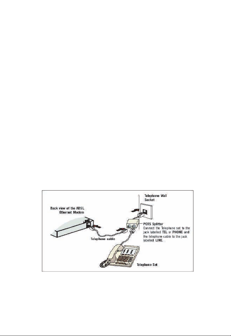
Connecting to the ADSL Line
Connect one end of the provided phone cable to the port labeled
DSL on the Rear Panel of the device. Connect the other end to
your wall phone jack.
To connect the ADSL Barricade to your computer,
you need to have an Ethernet port present on your
computer.
Note:
Included with specific models is a RJ-11 to RJ-45 cable
that will allow connection to an ISDN splitter for U-R2
compatibility.
7
Page 11

Configuration
Connecting to the Power Outlet
Connect the ADSL Barricade to the power outlet via the power
adapter which is included in your ADSL Barricade package.
Checking Your Connections
Please check your connections before proceeding.
Powering Up
Power on your computer.
Power on the ADSL Barricade.
Proceed to Step "Configuring Your Computers".
Configuring Your Computers
This section provides instructions for configuring
settings on your computers to work with the ADSL Barricade
the Internet
Before you begin
By default, the ADSL Barricade automatically assigns all required
Internet settings to your PCs. You need only to configure the PCs
to accept the information when it is assigned.
Note:
If you have connected your PC via Ethernet to the
Barricade
system installed on your PC.
In some cases, you may want to assign Internet
information manually to some or all of your computers
rather than allow the ADSL Barricade to do so. See
Assigning static Internet Information to your PCs for
instructions.
ADSL
, follow the instructions that correspond to the operating
8
.
Page 12

Configuring Your Computers
Windows® XP
1. In the Windows task bar, click the [Start] button, and then
click [Control Panel].
2. Double-click the [Netw ork Connections] icon.
3. In the [LAN or High-Speed Internet] window , right-click on
the icon corresponding to your network interface card (NIC)
and select [Properties]. (Often, this icon is labeled [Local
Area Connection].) The [Local Area Connection] dialog box
displays a list of currently installed network items.
4. Ensure that the check bo x to the left of the item labe led
[Internet Protocol (TCP/IP)] is checked, and click [Properties].
In the [Internet Protocol (TCP/IP) Properties] dialog box, click
5.
the radio button labeled [Obtain an IP a ddress automatically].
Also click the radio button labeled [Obtain DNS server
address automatically].
6. Click [OK] twice to confirm your changes, and close the
Control Panel.
Windows 2000
First, check for the IP protocol and, if necessary, install it.
1. In the Windows task bar, click the [Start] button, point to
[Settings], and then click [Control Panel].
2. Double-click the [Netw ork and Dial-up Connections] icon.
9
Page 13

Configuration
3. In the [Network and Dial-up Connections] window, right-click
the [Local Area Connection] icon, and then select [Properties].
The [Local Area Connection Properties] dialog box displays a
list of currently installed network components. If the list
includes [Internet Protocol (TCP/IP)], then the protocol has
already been enabled. Skip to Step 10.
4. If [Internet Protocol (TCP/IP)] does not appear as an installed
component, click [Install...].
5. In the [Select Network Component Type] dialog box, select
[Protocol], and then click [Add…].
6. Select [Internet Protocol (TCP/IP)] in the [Network Protocols]
list, and then click [OK]. You may be prompted to install files
from your Windows 2000 installation CD or other media.
Follow the instructions to install the files.
7. If prompted, click [OK] to restart your computer with the new
settings. Next, configure the PCs to accept IP information
assigned by the ADSL Barricade.
8. In the [Control Panel], double-click the [Network and Dial-up
Connections] icon.
9. In the [Network and Dial-up Connections] window, right-click
the [Local Area Connection] icon, and then select
[Properties].
10. In the [Local Area Connection Properties] dialog box, select
[Internet Protocol (TCP/IP)], and then click [Properties].
In the [Internet Protocol (TCP/IP) Properties] dialog box, click
11.
the radio button labeled [Obtain an IP address auto matically].
Also click the radio button labeled [Obtain DNS server
address automatically].
10
Page 14

Configuring Your Computers
12. Click [OK] twice to confirm and save your changes, and then
close the Control Panel.
Windows Me
1. In the Windows task bar, click the [Start] button, point to
[Settings], and then click [Control Panel].
2. Double-click the [Netw ork and Dial-up Connections] icon.
3. In the [Network and Dial-up Connections] window,
right-click the [Network] icon, and then select [Properties].
The [Network Properties] dialog box displays a list of currently
installed network components. If the list includes Internet
Protocol (TCP/IP), then the protocol has already been
enabled. Skip to Step 11.
4. If [Internet Protocol (TCP/IP)] does not appear as an installed
component, click [Add…].
5. In the [Select Network Component Type] dialog box, select
[Protocol], and then click [Add…].
6. Select [Microsoft] in the [Manufacturers] box.
7. Select [Internet Protocol (TCP/IP)] in the [Network Protocols]
list, and then click [OK]. You may be prompted to install files
from your Windows Me installation CD or other media. Follow
the instructions to install the files.
8. If prompted, click [OK] to restart your computer with the new
settings. Next, configure the PCs to accept IP information
assigned by the ADSL Barricade.
9. In the Control Panel, double-click the [Network and Dial-up
Connections] icon.
11
Page 15

Configuration
10. In the [Network and Dial-up Connections] window, right-click
the [Network] icon, and then select [Properties].
11. In the [Network Properties] dialog box, select [TCP/IP],
and then click [Properties].
12. In the [TCP/IP Settings] dialog box, click the radio button
labeled [Server assigned IP address]. Also click the radio
button labeled [Server assigned name server address].
13. Click [OK] twice to confirm and save y o ur chang es,
and then close the Control P an el.
Windows 95, 98
First, check for the IP protocol and, if necessary, install it.
1. In the Windows task bar, click the [Start] button, point
to [Settings], and then click [Control Panel].
2. Double-click the [Network] icon.
displays a list of currently installed
list includes [TCP/IP], then the protocol has already been
enabled. Skip to Step 9.
3. If [TCP/IP] does not appear as an installed component, click
[Add…]. The [Select Network Component Type] dialog box
appears.
4. Select [Protocol], and then click [Add...]. The [Sel ect Ne twork
Protocol] dialog box appears.
5. Click on [Microsoft] in the [Manufacturers] list box, and then
click [TCP/IP] in the [Network Protocols] list box.
The [Network] dialog box
network components. If the
12
Page 16

Configuring Your Computers
6. Click [OK] to return to the [Network] dialog box, and then
click [OK] again. You may be prompted to install files from
your Windows 95/98 installation CD. Follow the instructions to
install the files.
7. Click [OK] to restart the PC and complete the TCP/IP
installation. Next, configure the PCs to accept IP information
assigned by the ADSL Barricade.
8. Open the [Control Panel] window, and then click the [Network]
icon.
9. Select the network component labeled [TCP/IP], and then
click [Properties]. If you have multiple TCP/IP listings, select
the listing associated with your network card or adapter.
In the [TCP/IP Properties] dialog box, click the [IP Address]
10.
tab.
11. Click the radio button labeled [Obtain an IP address
automatically].
12. Click the [DNS Configuration] tab, and then click the radio
button labeled [Obtain an IP address automatically].
13. Click [OK] twice to confirm and save y our changes. You will
be prompted to restart Windows.
14. Click [Yes].
Windows NT 4.0
First, check for the IP protocol and, if necessary, install it.
1. In the Windows NT task bar, click the [Start] button, point to
[Settings], then click [Control Panel].
13
Page 17

Configuration
2. In the [Control Panel] windo w, double-click the [Network] icon.
3. In the [Network] dialog box, click the [Protocols] tab. The
[Protocols] tab displays a list of currently installed netw ork
protocols. If the list includes [TCP/IP], then the protocol has
already been enabled. Skip to Step 9.
4. If [TCP/IP] does not display as an installed component,
click [Add...].
5. In the [Select Network Protocol] dialog box, select [TCP/IP],
and then click [OK].
your Windows NT 4.0
the instructions to install
window appears to inform you that a TCP/IP service called
DHCP can be set up to dynamically assign IP information.
6. Click [Yes] to continue, and then click [OK] if prompted to
restart your computer. Next, configure the PCs to accept IP
information assigned by the ADSL Barricade.
7. Open the [Control Panel] window, and then double-clic k the
[Network] icon.
You may be prompted to install files from
installation CD or other media. Follow
the files. After all files are installed, a
8. In the [Network] dialog box, click the [Protocols] tab.
9. In the [Protocols] tab, select [TCP/IP], then click [Properties].
10. In the [Microsoft TCP/IP Properties] dialog box, click the
radio button labeled [Obtain an IP address from a DHCP
server].
11. Click [OK] twice to confirm and save your changes, and the n
close the [Control Panel].
14
Page 18

Configuring Your Computers
Assigning static Internet Information to your PCs
In some cases, you may want to assign Internet information to
some or all of your PCs directly (often called statically), rather
than allowing the ADSL Barricade to assign it. This option may
be desirable (but not required) if:
You have obtained one or more public IP addresses that
•
you want to associate with specific computers (for example, if
you are using a computer as a public web server).
You maintain different subnets on your LAN (subnets are
•
described in IP Addresses, Network Masks, and Subnets).
Before you begin, be sure to have the following informatio n on
hand (or contact your ISP if you do not know it):
The IP address and subnet mask you will assign to each PC
•
which will be assigned static IP information.
The IP address of the default gateway for your LAN. In most
•
cases, this is the address assigned to the LAN port on the ADSL
Barricade
address: [
another number
Configuring the LAN Ports for more information.
. By default, the LAN port is assigned this IP
192.168.1.1.] (You can change this number, or
can be assigned by your ISP.) See
The IP address of your ISP's Domain Name System (DNS)
•
server.
On each PC you will assign static information, follow the
instructions on pages 8 through 15 specific to the IP protocol.
Once it is installed, continue
displaying each of the Internet Protocol
Instead of enabling dynamic assignment of the IP addresses for
the computer, the DNS server, and the default gateway, click the
radio buttons that enable you to enter the information manually.
to follow the instructions for
(TCP/IP) properties.
15
Page 19
Configuration
Entering the Admin Page
To Login
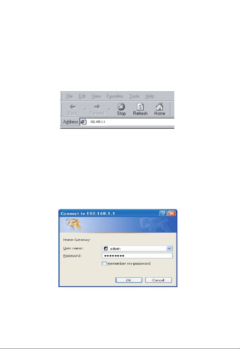
1. From your Internet Browser, you may enter the address
192.168.1.1 at the address bar and hit [Enter] key.
2. An [Enter Network Password] page will be displayed.
Enter the default User Name and Password.
The default login Username of the administrator is: admin.
The default login Password is: smcadmin.
The default login Username for the non-administrator is: user.
The default login Password is: password.
3. [Admin] page will be displayed.
16
Page 20
Entering the Admin Page
Status Page
The links under the [Status] option in top right corner are associated
to the pages that represent the status of system and interfaces.
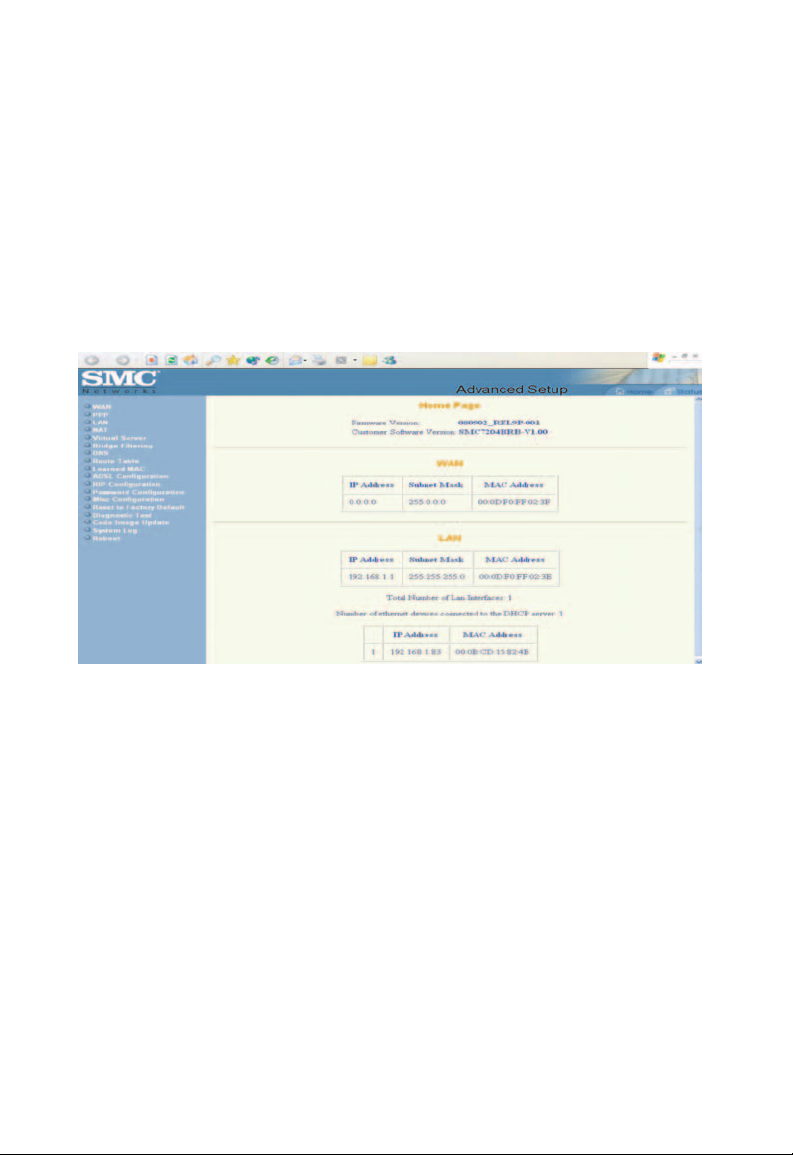
Home page
The [Home] page shows the firmware versions and WAN and
LAN interface status.
Home
[Firmware Version]
This field displays the firmware version number.
[Customer Software Version]
This field displays the customer's own firmware version number.
WAN
These fields display the [IP Address], [Subnet Mask] and
[MAC Address] for the WAN (ADSL) interface.
17
Page 21
Configuration
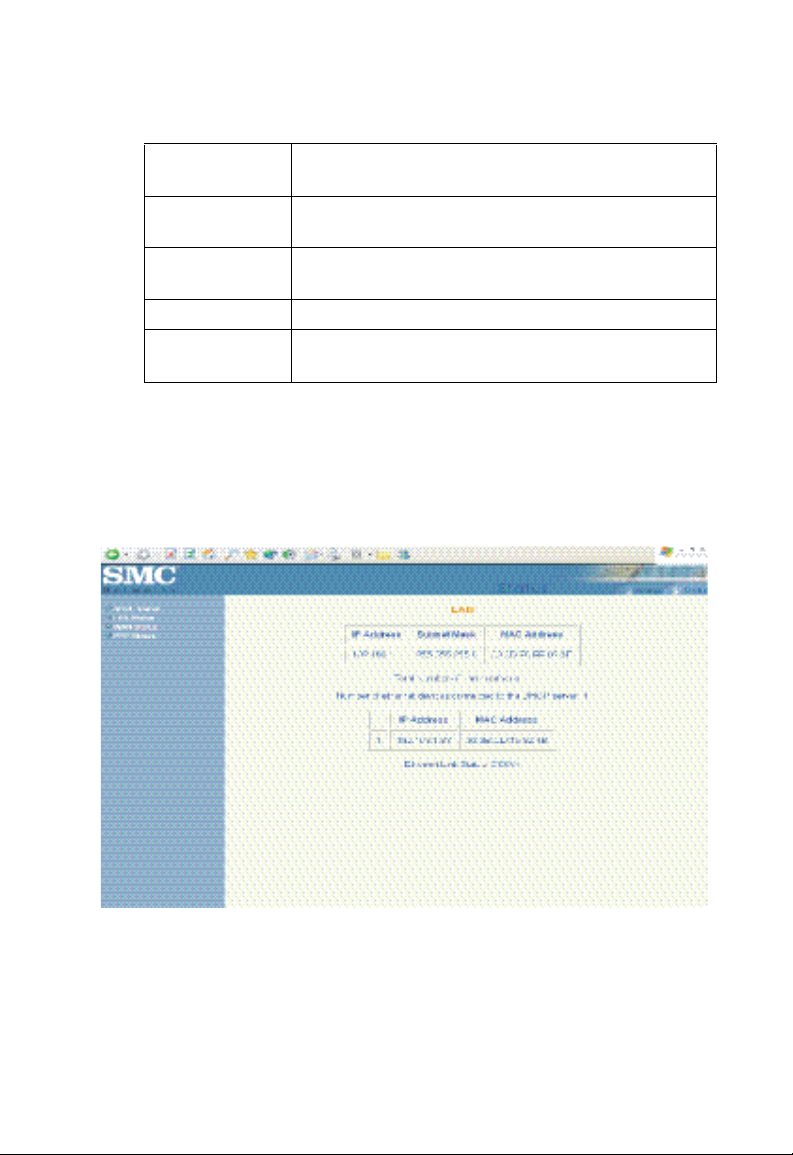
LAN
These fields display the [IP Address], [Subnet Mask] and
[MAC Address] for the LAN interface.
[Total Number of Lan Interfaces]
This field displays the total number of available interf ac es for the
LAN interface.
[Number of ethernet devices connected to the DHCP server]
These fields display the DHCP client table with the assigned IP
addresses and MAC addresses.
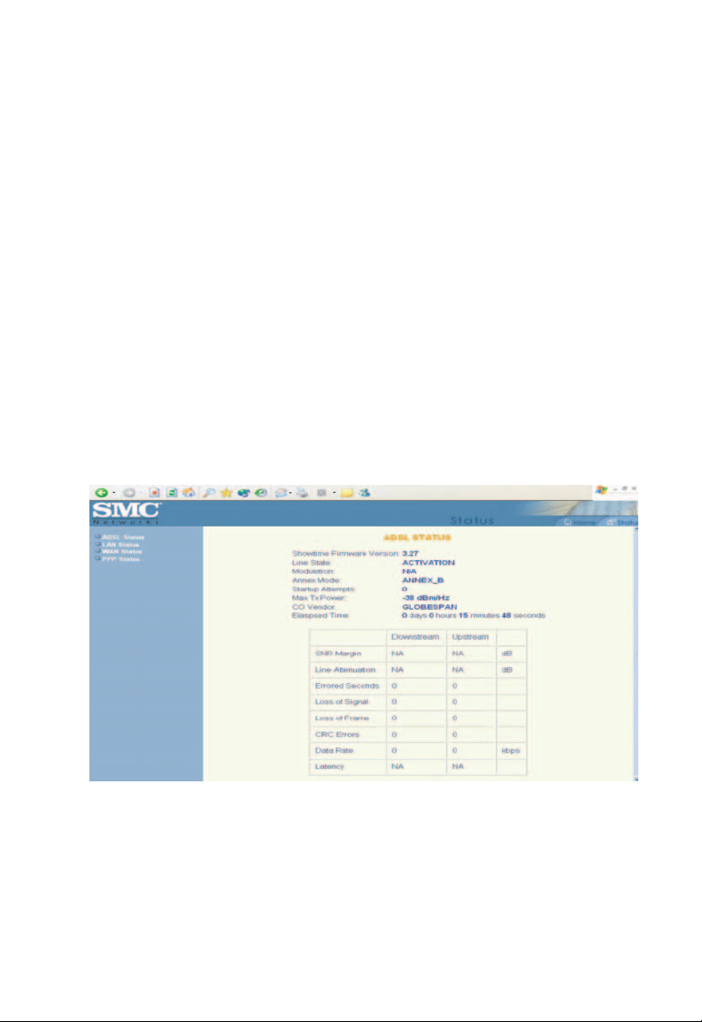
ADSL Status
The [ADSL Status] page shows the ADSL physical layer status.
18
Page 22

Entering the Admin Page
Showtime
Firmware
Version:
Line State: This field displays the ADSL connection process
Modulation: This field displays the ADSL modulation status
Annex Mode: This field displays the ADSL annex modes for
Startup Attempts:
Max Tx Power:
CO Vendor: This field displays the Central Office DSLAM vendor
Elapsed Time: This field displays the time of the modem has been
SNR Margin Amount of increased noise that can be tolerated while
Line Attenuation
Errored Seconds The error during Showtime, whenever, a given sec
This field displays the ADSL data pump firmware
version number.
and status.
for G.dmt or T1.413.
[Annex A] or [Annex B].
This field displays the ADSL connection attempts
after loss of showtime.
This field displays the transmit output power level
of the CPE.
name, if available.
in operation.
maintaining the designed BER (bit error rate). The
Margin is set by Central Office DSLAM. If the
SNR
SNR Margin is increased, bit error rate performance
will improve, but the data rate will decrease.
Conversely, if the SNR Margin is decreased, bit error
rate performance will decrease, but the
increase.
Attenuation is the decrease in magnitude of the ADSL
line signal between the transmitter (Central Office
DSLAM) and the receiver (Client ADSL Modem),
measured in [dB]. It is measured by calculating
the difference in dB between the signal power
level received at the Client ADSL modem and
the reference signal power level transmitted from
the Central Office DSLAM.
contains CRC error, that second will be declared
error second.
data rate will
19
Page 23
Configuration
Loss of Signal This field displays the count of event of ADSL
Loss of Frame This field displays the count of event of ADSL
CRC Errors This field displays the number of transmit data frames
Data Rate This field displays the ADSL data rate.
Latency
LAN Status
The [LAN Status] page shows the information and status
of LAN port, DHCP client table and Ethernet link.
signal loss.
frame loss.
containing CRC errors.
This field displays the latency modes for [fast]
or [interleave].
20
LAN
These fields display the [IP Address], [Subnet Mask] and
[MAC Address] for the[LAN interface].
Page 24
Entering the Admin Page
[Total Number of Lan Interfaces:]
This field displays the total number of available interfaces
for the LAN interface.
[Number of ethernet devices connected to the DHCP server:]
These fields display the DHCP client table with the
assigned IP addresses and MAC addresses.
[Ethernet Link Status:]
This field displays the link [UP] or [DOWN] for the Ethernet.
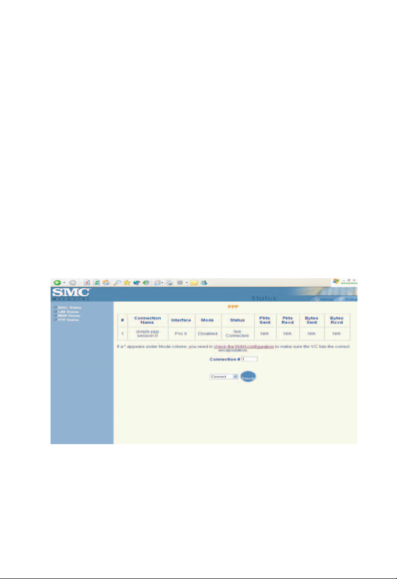
PPP Status
The [PPP Status] page shows the status of PPP for each
PPP interface.
PPP
These fields display the [Connection Name] (user defined),
[Interface] (PVC), [Mode] ([PPPoE] or [PPPoA]), [Status]
(Connected or Not Connected), [Packets Sent], [Packets
Received], [Bytes Sent] and [Byte Received].
21
Page 25
Configuration
[Connect:]
[Disconnect:]
These fields allow the user to manually connect/disconnect the
PPP connection for each PPP interface. In another word, each
PPP session can be connected and disconnected individually.
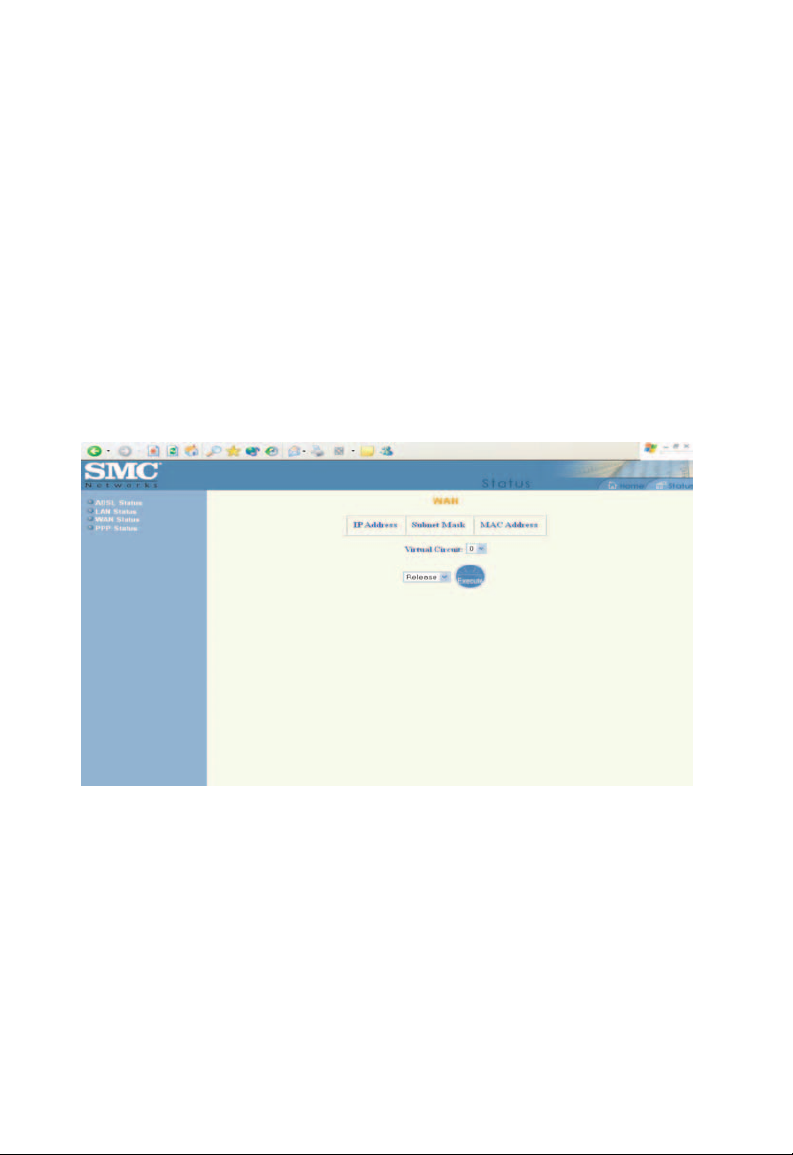
WAN Status
The [WAN Status] page shows the information and status
of WAN PVCs.
WAN
These fields display the [IP Address], [Subnet Mask] and [MAC
Address] for the WAN (ADSL) interface. Use the [Virtual Circuit]
selection to select different PVC for status display.
DHCP Release and Renew
This field allows the user to release and renew the WAN IP
address in the WAN DHCP Client Enabled (dynamic) mode.
22
Page 26
WAN Configuration
Entering the Admin Page
Warning:
Note:
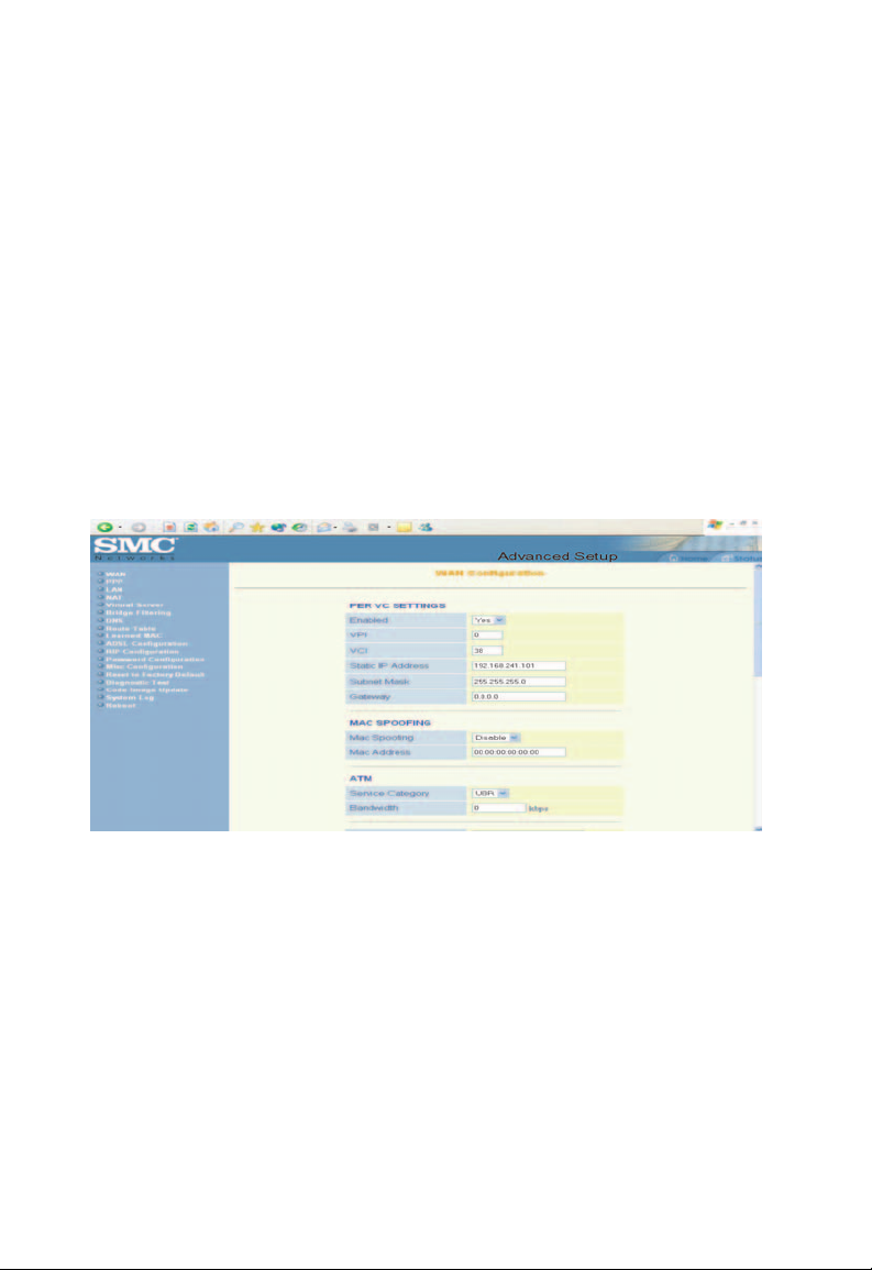
The [WAN Configuration] page allows the user to set
the configuration for the WAN/ADSL ports.
The links in the left hand column are associated to
the pages that represent the configurations of
system and interfaces.
When the configurations are changed, please
submit changes and go to the [Reboot] page to
save the new setting and reboot the board.
Per VC Settings
Under [Per VC Setting], you will find the configurations for [VPI /
VCI], [Static IP Address], [Subnet Mask], and [Gateway].
The Static IP Address, Subnet Mask and Gateway are used for
Static IP configuration. Current firmware supports eight PVCs.
To switch between the PVCs, please choose th e options of
virtual circuit and click on the [Submit] button.
23
Page 27

Configuration
MAC Spoofing
The MAC Spoofing is developed to solve the scenario when the ISP
only recognizes one MAC address. Copy the ISP-recogn ize d MAC
address here.
ATM
[Service Category]
[Bandwidth] Bandwidth setting takes effect only when the CBR
Encapsulation, Bridge, PPP and DHCP Client
Use the following table to configure a valid setting for each PVC.
[UBR] and [CBR] are supported from the ATM.
is selected.
The maximum available bandwidth is from the
upstream data rate of [ADSL Status] page.
WAN
Configuration
Bridge
Mode
Router Mode
(PPPoA /
Router Mode
(Dynamic IP)
PPPoE)
IP address N/A Automatically
assigned by ISP
Subnet Mask N/A Automatically
assigned by ISP
Gateway N/A Automatically
Encapsulation 1483 Bridged
IP LLC, 1483
Bridged IP
VC-Mux
Bridge Enabled Disabled Disabled Disabled
PPP Service N/A Provided
PPP
User name
N/A Provided
assigned by ISP
PPPoA LLC/
VC-Mux, PPPoE
LLC/VC-Mux
by ISP
by ISP
Automatically
assigned by ISP
Automatically
assigned by ISP
Automatically
assigned by ISP
1483 Bridged/
Routed IP LLC,
1483 Bridged
Routed
VC-Mux,
Classical IP
over ATM
N/A N/A
N/A N/A
24
Router
Mode
(Static IP)
Provided
by ISP
Provided
by ISP
Provided
by ISP
1483 Bridged/
Routed IP
LLC, 1483
Bridged
Routed
VC-Mux,
Classical IP
over ATM
Page 28

Entering the Admin Page
PPP
Password
DHCP Client
enable
N/A Provided
by ISP
Unchecked Unchecked Checked Unchecked
N/A N/A
Bridge
Select [Enabled] or [Disabled] to enable or disable the bridge
mode.
IGMP
IGMP relay/proxy specification and environment:
Supports IGMP proxy/relay function, based on the following
condition and case:
On CO side, there must be at least one IGMP querier (router)
present. IGMP querier will send IGMP query packet. The ADSL
Gateway is responsible to relay IGMP queries to Ethernet.
End-user multicast application device sends IGMP report while
receiving IGMP query or being activated by user, the ADSL
Barricade should be responsible to proxy (that is, change source
25
Page 29

Configuration
IP
to ADSL Barricade's WAN IP) the IGMP report to ADSL WAN
side, includes all PVCs. The same applies for IGMP leave
packet.
It is not necessary to relay multicast routing between two ADSL
PVCs or two interfaces in LAN side.
Special purpose multicast packet (such as RIP 2 packet) should
run without interference.
Packet Process
Rx Entity Packet Class TTL Action Notes
ADSL IGMP query 1 Relay to Ethernet
IGMP report 1 Ignore
IGMP leave 1 Ignore
General Multicast IP - Relay it to Ethernet
Ethernet IGMP query 1 Ignore
IGMP report 1 Relay to all ADSL PVC
IGMP leave 1 Relay to all ADSL PVC
General Multicast IP - Ignore
26
Note: Before the IGMP mode is enabled, please go to
the [Miscellaneous Configuration] page to enable
the IGMP proxy. Otherwise, the IGMP selection
will not be val
id.
PPP
The current release supports multiple PPP sessions per PVC.
The PPP configuration in the [WAN Configuration] page is for
the first PPP session for each PVC. The predefined PPP Accou nt
Name (Account ID) is Simple PPP Account 0 for PVC0 and
predefined PPP Connection Name is Simple PPP Session 0
for PVC0. For the other PVC X, the predefined account name
and connection name will be Simple PPP Account X and Simple
PPP Session X. X is the PVC number from 1 to 7.
Page 30

Entering the Admin Page
It can support up to total of 16 PPP sessions, and each PVC
can support up to 8 PPP sessions. The multiple PPP sessions
may be configured with any combination over 8 PVCs.
For the multiple PPP sessions, please go to [PPP Configuration]
page.
Service Name
Username The username you use to log in to your ISP.
Password The password you use to log in to your ISP.
Disconnect
Timeout
MRU Maximum Receive Unit indicates the peer of PPP
MTU Maximum Transmission Unit (MTU) value will be
MSS Maximum Segment Size is the largest size of data that
The service name of PPP is required by some ISPs.
If the ISP does not provide the Service Name, please
leave it blank.
The Disconnect Timeout allows the user to set the
specific period of time to disconnect from the ISP.
The default is [0], which means never disconnect
from the ISP.
connection the maximum size of the PPP information
field this device can recieve. The default value is 1492
and is used in the beginning of the PPP negotiation. In
the normal negotiation, the peer will accept this MRU
and will not send packets with information field larger
than this value.
fragmented before the transmission. During the PPP
negotiation, the peer of the PPP connection will
indicates its MRU and will be accepted. The actual MTU
of the PPP connection will be set to the smaller one of
MTU and the peer’s MRU. The default is value [1492].
TCP will send in a single IP packet. When a connection
is established between a LAN client and a host in the
WAN side, the LAN client and the WAN host will indicate
their MSS during the TCP connection handshake.
The default value is [1432].
27
Page 31

Configuration
Authentication
Automatic
Reconnect
When [Auto] option is chosen, the PAP mode will run
first then CHAP.
When it is checked, it will maintain the PPP connection
time. If the ISP shut down the PPP connection,
all the
it will automatically
reconnect PPP session.
DHCP
[DHCP client enable]
This item allows to enable DHCP client.
[Host Name]
It may be required by some ISPs. If the ISP does not provide the
Host name
, please leave it blank.
Virtual Circuit
Interface between Access Node and network. It supports interface
to 7. The default value is 0.
28
0
Page 32

Entering the Admin Page
LAN Configuration
The [LAN Configuration] page allows the user to set
the configuration for the LAN port.
LAN Configuration
[IP Address] [Subnet Mask]
The default is [192.168.1.1] and [255.255.255.0].
User can change it to other private IP address.
DHCP Server
System
Allocated
User Defined The DHCP address pool is at the range of [User Defined
The DHCP address pool is based on LAN port IP
address plus 12 IP addresses. For
IP address is 192.168.1.1;
at the range of 192.168.1.10 to 192.168.1.100.
Start Address] and [User
maximum pool
IP addresses – 1 broadcast address – 1 LAN port IP
address.
size can be 253 IP addresses: 255 total
the DHCP address pool is
Defined End Address]. The
example, the LAN
29
Page 33

Configuration
DHCP
gateway
selection
Lease Time The Lease time is the amount of time a network user will
User Mode Under the [Single-User] mode, the DHCP server only
The default setting for the DHCP
[Automatic]. The user
[User Defined Gateway Address]. The DHCP server will
issue the User Defined
to the LAN DHCP clients.
be allowed to connect with DHCP server. If all fields are
0, the allocated IP addresses will be effective forever.
allocates one IP address to local PC. Under the
[Multiple-User] mode,
IP addresses
specified by the DHCP address pool.
can select [User Defined] to specify
Gateway Address
the DHCP server allocates the
Gateway Selection is
Ethernet Mode Setting
The [Ethernet Mode configuration] page allows the user to set
the LAN port to Auto Sense, 100 Mbps Full Duplex, 100 Mbps
Duplex, 10 Mbps Full Duplex or 10 Mbps Half Duplex.
PPP Configuration
The [PPP Configuration] page allows the user to configure multiple
PPP sessions for each PVC. It can support up to total of 16 PPP
sessions, and each PVC can support up to 8 PPP sessions. The
multiple PPP sessions may be configured with any combination
over 8 PVCs.
Half
30
T
o configure the PPP, must go to the [PPP Account Configuration]
page first to configure [Account ID], [Users Name] and [Password].
Page 34

Entering the Admin Page
Acct ID
User Name Enter the PPP user name (usually provided by the ISP).
Password Enter the PPP password (usually provided by the ISP).
This field allows the user to enter his own
distinguish different accounts.
account ID to
[PPP Account Configuration] Status will be displayed at the
bottom of this page to show all the accounts with its [Account
Name] and [User Name]. (It does not show the password.)
The Number of
PPP Accounts
This field displays the total number
of PPP Accounts entered.
31
Page 35

Configuration
Session Name This field allows the user to enter his own session
PVC This field allows the user to choose the specific PVC
Service Name
(PPPoE only)
Disconnect
Timeout
MRU Maximum Receive Unit indicates the
MTU Maximum Transmission Unit indicates
MSS Maximum Segment Size is the largest size of data that
Authentication
Automatic
Reconnect
Name to distinguish different sessions for different
PPP accounts and different PVCs.
for PPP session.
The service name of PPP is required by some ISPs.
If the ISP does not provide the Service Name, please
leave it blank.
The Disconnect Timeout allows the
specific period of time
The default is [0], which means never disconnect
from the ISP.
connection the maximum
field this device can be received. The default value
is [1492] and is used at the beginning of the PPP
negotiation. In normal negotiation, the peer will accept
this MRU and will not send packet with information field
larger than this value.
of any packet is larger
before the transmission. During the PPP negotiation,
the peer of the PPP connection will indicates its MRU
and will be accepted. The actual MTU of
connection will be set to the
the peer's MRU. The default is value [1492].
TCP will send in a
is established between a LAN client and a host in the
WAN side, the LAN client and the WAN host will indicate
their MSS during the TCP connection
The default value is [1432].
When [Auto] option is chosen, the PAP mode will run
first then CHAP.
When it is checked, it will maintain the PPP connection
all the time. If the ISP shuts down the PPP connection,
it will automatically reconnect PPP session.
to disconnect from the ISP.
size of the PPP information
than this value will be fragmented
smaller one of MTU and
single IP packet. When a connection
user to set the
peer of PPP
the network stack
the PPP
handshake.
32
Page 36

Entering the Admin Page
PPP Configuration Status will be displayed at the bottom
of this page to show all the Session Names with its [Adapter]
(PVC number), [Mode] ([PPPoA] or [PPPoE]), [Service Name],
[Account to Use] (PPP Account ID), [Disconnect Timeout]
configuration, [MRU], [
([Auto], [CHAP] or [PAP]), and [Auto
MTU], [MSS], [Authentication Mode]
Reconnect] configuration.
NAT Configuration
The [NAT Configuration] page allows the user to set the
configuration for the Network Address Translation. The default
setting is [Dynamic NAPT]. It provides dynamic Network Address
Translation capability between LAN and multiple WAN connections,
and the LAN traffic is routed to appropriate WAN connections based
on the destination IP addresses and Route Table. This eliminates
the need for the static NAT session configuration between multiple
LAN clients and multiple WAN connections.
When the [Dynamic NAPT] is chosen, there is no need to configure
the NAT Session and NAT Session Name Configuration.
NAT (Static) and NAPT (Static)
The [NAT] option only maps single WAN IP address to the local
PC IP address. It is peer-to-peer mapping. (1x1) For each WAN
interface, only one local PC IP address can be associated with
each WAN interface. Click the link [Session Name Configuration]
to add the session name for WAN interface.
The [NAPT] option maps the single WAN IP address to many
local PCs IP addresses. (1xN). It is the multiple-mapping
mechanism. For each WAN Interface, more than one local
PCs can be associated with one WAN Interface. Click the link
[Session Name Configuration] to add the session name for
WAN interface.
33
Page 37

Configuration
NAT Configuration
Session Name This field allows the user to select the
User's IP This field allows the user to assign the IP
session from the configured NAT Session
Name Configuration.
address to map the corresponding NAT/
NAPT sessions.
34
[Session Name] Status will be displayed at the middle of this
page to show the corresponding Session Name with its IP
address.
Number of NAT
Configurations
This field displays the total number
of NAT Sessions entered.
[Available Sessions] Status will be displayed at the end of this
page to show all the Session Names with its WAN Interface.
Number of Session This field displays the total numbe r of NAT
Sessions.
Page 38

Entering the Admin Page
NAT Session Name Configuration
Session Name: This field allows the user to enter his/her own session
Name to distinguish different NAT sessions for
different interfaces among different PPP sessions and
different PVCs.
Interface: This field allows the user to choose specific WAN
Interface ([PVC] or [PPP] Session) for NAT Session.
NAT Session
Name Status:
Number of NAT
Configurations:
This table displays at the bottom of
all the NAT Session
This field displays the total number of NAT
configurations.
Names with its WAN Interface.
Click the link [Go back to NAT Configuration] to the [NAT
Configuration] page. Select the [NAT] option. Select the [Session
Name] and assign the PC IP address, and choose t he [Add] action.
Click the [SUBMIT] button and go to the [Save Settings] t o save
this
configuration.
[NAT] allows only one entry (User IP) per session.
[NAPT] allows many entries (User IPs) per session.
this page to show
Virtual Server Configuration
The [Virtual Server Configuration] page allows the user to set the
configuration of Virtual Server. The Conexant firmware includes
the Free BSD version firewall. All UDP/TCP ports are protected
from intrusion. If any specific local PCs need to be mapped to the
[
UDP/TCP] port on WAN side, please input the mappings here.
35
Page 39

Configuration
Public Port: This field allows the user to enter the
Private Port: This field allows the user to enter the
Host IP Address: This field allows the user to enter the
port number of the Public Network.
port number of the Private Network.
In
most cases, the private port number is
same as public port number.
private network IP address for the
particular sever.
36
Well Known Ports:
Port Protocol Port Protocol
21 FTP 79 Finger
23 Telnet 80 HTTP
25 SMTP 110 POP3
43 Whois 115 SFTP
53 DNS 161 SNMP
69 TFTP 162 SNMP traps
Page 40

Entering the Admin Page
Port Protocol Port Protocol
70 Gopher
DNS Configuration
The [DNS Configuration] page allows the user to set the
configuration of DNS proxy. The firmware supports the DNS
proxy function. For the DHCP requests from local PCs, the
DHCP server will set the LAN port IP as the default DNS server.
Thus, all DNS query messages will come into LAN port first.
The DNS proxy on the ADSL Barricade records the available
DNS servers, and forward DNS query messages to one DNS
server.
[Disable DNS Proxy]
The LAN port does not process the DNS query message. For
the DHCP requests from local PCs, the DHCP server will set the
user-configured preferred DNS server or alternate DNS server
whichever is available as the DNS server. Then all DNS query
messages will be directly sent to the DNS servers.
37
Page 41

Configuration
[Use Auto Discovered DNS Servers Only]
The DNS proxy will store the DNS server IP addresses
obtained from DHCP client or PPP into the table. And all
DNS query messages will be sent to one of the dynamically
obtained DNS servers.
[Use User Configured DNS Servers Only]
The DNS proxy will use the user-configured preferred DNS
server and alternate DNS server. And all DNS query message
will be sent to one of DNS servers. Enter the [DNS IP] in the
[Preferred DNS Server] and [Alternate DNS Server] fields.
[Auto Discovery + User Configured]
The DNS proxy’s table has all the IP addresses of dynamically
obtained and user configured DNS servers.
Bridge Filtering Configuration
The [Bridge Filtering Configuration] page allows the user to set
the configuration of IP filtering.
38
Page 42

Entering the Admin Page
ID Source
MAC:
Destination
MAC:
Type: Enter the [hexadecimal number] for the Ethernet type
When the bridge filtering is enabled, enter the [Source
MAC address], select [Block]
incoming WAN and
with this source MAC address will be filtered out. If the
[Forward] is selected, then the packets will be
forwarded to the destination PC.
When the bridge filtering is enabled, enter the
[Destination MAC address], select [Block] and click
[Add]. Then all incoming WAN and LAN Ethernet
packets matched with this destination MAC address
will be
filtered out. [Forward] is selected, then the
packets will be forwarded to the destination PC.
field in Ethernet_II packets. For example, 0800 is for
IP protocol.
LAN Ethernet packets matched
and click [Add]. Then all
Route Table
The [Route Table] page displays routing table and allows the
user to manually enter the routing entry. The routing table will
display the routing status of [Destination], [Netmask], [Gateway],
and [Interface].
The interface lo0 means the loopback interface.
The interface ppp1 means the PPP interface.
The Gateway is the learned Gateway.
39
Page 43

Configuration
System Default Gateway Configuration
The system-wide Default Gateway now provides three options:
None, Auto, Selected In terface.
None: This field allows the user to choose to have no Default
Gateway in the CPE.
Auto:
Selected
Interface:
This field allows the user to select the CPE
to
automatically decide the Default Gateway.
(System Default)
This field allows the user to select a Network Interface
from a list ([PVCs], [PPP Sessions] and [LAN]). This
option lets the user to associate the system-wide Default
Gateway to a Network Interface, static or dynamic, and
provides a way to fix the Default Gateway to a dynamic
Network Interface before the interface is established.
40
Page 44

Route Configuration
Entering the Admin Page
Destination
Netmask
Gateway This field allows the user to enter the IP address of the
Manually
Configured
Routes
This field allows the user to enter the remote
or host IP address for the static routing.
This field allows the user to enter the [Subnet
static routing.
gateway device that allows the router to contact the
remote network, or Select the Interface for the Gateway.
This field displays the static route entries entered
by the user.
Learned MAC Table
The Learned MAC Table page shows the current learned
[Bridge MAC table].
network
Mask] for the
41
Page 45

Configuration
Aging
Timeout
his field allows the user to enter the update displays
T
period for the MAC table.
ADSL Configuration
The [ADSL Configuration] page allows the user to set the
configuration for ADSL protocols.
42
Trellis This field allows the user to [Enable] or [Disable] the
Trellis Code. By default, it is always [Enabled].
Handshake
Protocol
This field allows the user to select the ADSL handshake
protocol.
Page 46

Entering the Admin Page
Wiring
Selection
Bit Swapping This field allows the user to [Enable] or [Disable] the
This field allows the user to enter the wiring selection for
the RJ-11. [Tip/Ring] is the default for the board without
the inner/outer pair relay.
upstream bit swapping.
RIP Configuration
The [RIP System Wide Configuration] page allows the user to set
the configuration for the system wide configuration of RIP. The
actual RIP configuration is in the RIP Per Interface Configuration.
43
Page 47

Configuration
RIP
Supply
Interval
Expire
Timeout
Garbage
Timeout
This field allows the user to enable or disable
session. The resulting RIP session will monitor all network
interfaces that are currently available for messages from
other RIP routers.
This field allows the user to enter the Supplier Interval
timer in seconds. This timer specifies how often RIP
sends announcements as a RIP Supplier.
(Default: 30 seconds)
This field allows the user to enter the Expire
seconds. This timer specifies the
When a route has not
period of time, it is removed from the Route Table. This
route is invalidated and remains in the internal RIP Route
Table. It will be included in the RIP announcements to let
other routers know the changes.
(Default: 180 seconds)
This field allows the user to enter the Garbage timer in
seconds. This timer specifies how long the expired and
invalidated routes are kept in the Internal RIP Route Table
before it is removed from it.
(Default: 300 seconds)
been updated for more than expire
expiration time of a route.
the RIP
timer in
RIP Per Interface Configuration
The [RIP Per Interface Configuration] page allows the user to set
the configuration for each Interface (PVCs, PPP Sessions and
LAN).
44
Interface This field allows the user to choose the Interface (PVCs,
PPP Sessions and LAN), for the RIP to be configured.
Enable
This field allows the user to [Enable] (Yes) or [Disable] (No)
the specified interface for RIP
.
Page 48

Entering the Admin Page
Supplier This field allows the user to select the Supplier Mode (RIP
Transmit).
- [Disabled] The supplier transmit is disabled.
- [V1 BC] The supplier transmits in RIPv1 Broadcast.
- [V2 BC] The supplier transmits in RIPv2 Broadcast.
- [V2 MC] The supplier transmits in RIPv2 Multicast.
Listener
Current RIP
Settings
This field allows the user to select the Listener
Receive).
- [V1]: The listener receives the RIPv1 only.
- [V2]: The listener receives the RIPv2 only.
- [V1+V2]: This listener receives the both RIPv1 and RIPv2.
This field displays the RIP status of each interface.
Mode (RIP
45
Page 49

Configuration
Password Configuration
The [Password Configuration] page allows the user to set
the password for administrator.
The Admin password is the same as the FTP password,
so it must have at least 8 characters for the FTP to work.
46
Page 50

Miscellaneous Configuration
The [Miscellaneous Configuration] allows the user to set
all the miscellaneous configurations.
HTTP server
access
HTTP
server port
This field allows the user to configure so the Web pages
can be accessed from.
- [All]
When this field is checked, both WAN and LAN access
to the Web pages are allowed.
- [LAN]
If [Restricted] has been selected,
pages access from LAN side.
- [WAN]
[Restricted] may be selected.
- [WAN specify IP]
[Subnet Mask]
These fields allow the Web access from WAN side with a
Specify IP and Subnet Mask.
This field allows the user to specify the port of the
Web access. For example, wh en it is
the HTTP server address for the LAN side is
http://192.168.1.1:1001.
this field allows the Web
changed to 1001,
47
Page 51

Configuration
FTP server This field allows the user to select [Enable] or [Disable] to
TFTP server This field allows the user to [Enable] or [Disable]
enable/disable the FTP connection.
the TFTP connection.
48
DMZ A DMZ (De-Militarized Zone) is added between a
protected network and an external network, in order
to provide an additional layer of security. When there
is a suspected packet coming from WAN, the firewall
will forward this packet to the DMZ host.
DMZ Host IP
DHCP
Relay
DHCP
Target IP
This is the IP address of the DMZ host at LAN side.
If set to [Enable], the DHCP requests from local PCs are
forwarded to the DHCP server runing on WAN side. To
have this function working properly, [Disable] NAT and
DHCP server on LAN side, also make sure the routing
table has the correct routing entry.
This is the DHCP server running on WAN side.
Page 52

Entering the Admin Page
IGMP Proxy This is the global setting for IGMP Proxy. If [Enabled] has
been selected, then the enabled IGMP Proxy on WAN
PVCs will be working. Otherwise, no WAN PVC can have
IGMP Proxy working on it.
PPP
reconnect on
WAN access
PPP Half
Bridge
If [Enabled] has been selected, the PPP
automatically established
the WAN.
When [Enabled] has been selected for the PPP Half
Bridge, only one PC is able to access the Internet, and
the DHCP server will duplicate the WAN IP address
from the ISP to the local client PC. Only the PC with the
WAN IP address can access the Internet.
when a packet wants to go out
Reset to Factory Default
The [Reset to Factory Default] page allows the user to reset the
modem to original factory default configuration.
session will be
49
Page 53

Configuration
Diagnostic Test
The [Diagnostic Test] page shows the test results for the
connectivity of the physical layer and protocol layer for both
LAN and WAN sides.
50
Testing Ethernet
LAN Connection
Testing ADSL
Synchronization
Test ATM OAM
Segment Loop
Back
This test checks the Ethernet
connection.
This test checks the ADSL showtime. If this test
returns FAIL, all other tests will be skipped.
This test sends ATM OAM
request cells to the CO. This test will pass if response
cell is received.
support this test, it could still work even if this test
not
fails. If this test fails consistently and the ADSL
Barricade seems to be not working, make sure
[VPI]
and [VCI] are configured correctly.
Since some service providers might
LAN interface
F5 Segment loop back
the
Page 54

Entering the Admin Page
Test ATM OAM
End-to-End
Loop Back
Test Ethernet
Connect to ATM
Test PPPoE
Connection
Test PPP Layer
Connection
Test IP
Connect to PPP
Ping
Primary DNS
Query DNS for
168.95.1.1
Ping
168.95.1.1
This test sends ATM OAM
request cells to the CO. This test will pass if response
cell is received. Since some service providers might
not support this test, it could still work even if this test
fails. If this test return FAIL consistently and the
ADSL Barricade seems not to be working, make sure
the [VPI] and [VCI] are configured correctly.
This test checks the ATM AAL5 module is loaded
correctly.
This test checks the PPPOE connection.
This test checks the PPP authentication.
This test checks a valid IP address assigned by
the service provider.
This test checks the primary DNS can be reached
through ping request.
This test checks the host name can be resolved to
IP address though domain name servers.
This test checks the specified
through ping request.
F5 End to End loop back
host can be reached
51
Page 55

Configuration
Code Image Update
The [Code Image Update] page allows the user to upgrade
the image code locally.
Browse the location of file, firmware.dlf file, and click [Upload
start the update.
52
] to
Page 56

Entering the Admin Page
System Log
The [System Log] page shows the events triggered by the system.
[Clear] This field allows the user to clear the current
contents of the System Log.
[Save] This field allows the user to save the current
contents of the System Log by right-clicking
[Here] and selecting [Save Target As] to save
it as a text file.
The System Log records:
DSL Layer
•
– DSL Link detected
– DSL Link connected
– DSL Link disconnected
53
Page 57

Configuration
ATM Layer
•
– ATM detected
– ATM connected
– ATM disconnected
– ATM setting up VPI/VCI
PPP Layer
•
– PPP authenticated
– PPP invalid user name or password
– PPP unable to connect with PPP server
IP Layer
•
– IP protocol up
– PPP IP address
– PPP Gateway IP address PPP DNS Primary IP address
– PPP DSN Secondary IP address
54
Page 58

Entering the Admin Page
Reboot/Save Configuration
The [Reboot] page allows the user to save the new configuration
to flash, and reboot the system.
When configurations are changed via the Web pages, the new
settings need to be saved to flash, so it is necessary to go to
[Reboot] page to save and reboot the system for the changes to
take effect.
During Save and Reboot, the following Web page will appear
[Your setting are being saved and the modem is being rebooted.
Please wait…].
After Save and Reboot, the following Web page will appear
setting have been saved and the modem has rebooted.].
this
[Your
55
Page 59

ROUBLESHOOTING
T
Cannot connect to the Internet
Make sure you've securely connected the RJ-11 phone card from
the wall jack to the ADSL Barricade connector.
Make sure you've connected the RJ-11 phone cord to the ADSL
line
,
not a standard telephone jack. You cannot use a standard
telephone jack for ADSL service unless that phone line has been
enabled for ADSL by your phone service provider.
Make sure, if you are using phone filters, that they are installed
correctly.
Make sure you have typed your Username and Password correctly.
Contact your service provider to make sure that the DSL
connection is functioning properly.
Hear noise when using telephone
If that phone does not have its own filter, you may hear static
or high-pitched noise if you make a phone call while your ADSL
Barricade
with, or dropping, your DSL connection.
is on. A filter also prevents a phone from interfering
If the PPP is disconnected after the Disconnect Timeout
and how can I reconnect it?
You have to go to the [PPP Status] under [Admin] Page, choose
the
correct [PVC] and [Connect] option, and then click [Execute]
to restart a new PPP session.
57
Page 60

Troubleshooting
What is the difference between PPP connect on WAN access
and the Automatic Reconnect?
Some ISPs terminate the PPP session for inactivity reasons.
If [PPP connect on WAN access] is selected, the PPP will be
automatically reconnected when an URL is entered in
the browser (packet interested in going out the WAN).
If [Automatic Reconnect] is selected, it will reconnect the PPP
session whenever it is terminated by ISP.
58
Page 61

ECHNICAL
T
PECIFICATIONS
S
Interface Ports
- Internet (WAN): ADSL RJ11 (pin 3 and 4)
- Network (LAN): 4-Port 10/100 Mbps Ethernet switch
(Auto MDI/MDI-X)
ADSL Features
- Embedded full-rate ADSL Modem Compliant with ANSI
T1.413 Issue 2 , ITU G.992.1 (G.DMT) and ITU G.992.2
(G.Lite) and ITU G.994.1 (G.hs)
- G.DMT full-rate connectivity at up to 8 Mbps downstream,
1 Mbps upstream
- Up to 18,000 feet loop reach (over standard loops)
ATM and AAL Support
- AAL5
- ATM Transmission Convergence (TC) layer
- Support for full range of PVC settings
- Hardware SAR
59
Page 62

Technical Specifications
Standards Compliance
- ADSL:
ANSI T1.413 Issue 2
G.DMT (ITU G.992.1)
G.Lite (ITU G.992.2)
G.hs (ITU G.994.1)
- Ethernet:
IEEE 802.3 10 Base-T Ethernet
IEEE 802.3u 100 Base-TX Fast Ethernet
- ATM Protocols and Encapsulations:
PPP over ATM VCMUX ( RFC 2364 )
PPP over ATM LLCSNAP ( RFC 2364 )
Bridged IP over ATM LLCSNAP ( RFC 1483 )
Routed IP over ATM LLCSNAP ( RFC 1483 )
Bridged IP over ATM VCMUX ( RFC 1483 )
Routed IP over ATM VCMUX ( RFC 1483 )
Classical IP over ATM ( RFC 1577 )
PPP over Ethernet VCMUX ( RFC 2516 )
PPP over Ethernet LLCSNAP ( RFC 2516 )
8 PVCs
VPI / VCI range 0-255 , 0-65535
Encapsulation hunting of up to 8 pre-defined VPI / VCI &
encapsulation sets
AAL5 UBR & CBR
OAM F4/F5
60
Page 63

- Firmware Features:
IEEE 802.1D
128 MAC addresses support
Static IP routing
RIPv2 (Backward compatible with RIPv1 )
DHCP server (configurable and supports up to 253
addresses )
DHCP client ( WAN )
DHCP relay
PPP auto, PAP and CHAP
DNS proxy
NAT
NAPT
Dynamic NAPT
ALG support
Wild Card DMZ
Virtual server
VPN pass through ( IPSec - ESP Tunnel mode, L2TP,
PPTP )
Bridge filtering
ICMP
IGMP
MAC address spoofing
Auto VPI / VCI PPPoE / PPPoA detection
Multiple PPP sessions per PVC
Technical Specifications
- Management:
HTTP client and server
Password protection
61
Page 64

Technical Specifications
Configuration Web pages
FTP server
FTP client ( for network upgrade )
Local firmware upgrade via Web configuration pages
Remote firmware upgrade via FTP client
Telnet
Restore to Factory defaults via Web or hardware reset
Operating System Support
Supports Windows 95, 98, 2000, Me, SE, XP, Linux, Mac OS 8.5
and above
Environmental Operating Range
Operating temperature : 0-40 degrees Celsius
Humidity: 0-90%, non-condensing
Power Dissipation
The typical approximated power dissipation is as below:
Power Dissipation for RL800C
Active (typical) 6.24W
Power Input
12V/1.2A
62
Page 65

Weight
545g
Dimensions
20 x 14.8 x 3.9 cm (LxWxH)
Electromagnetic Compatibility
CE R&TTE, FCC part 15 class B and FCC part 68
Safety
CSA,UL 1950, EN60950
63
Page 66

ERMINOLOGY
T
10BASE-T
A designation for the type of wiring used by Ethernet networks
with a data rate of 10 Mbps. Also known as Category 3 (CAT 3)
wiring. See also data rate, Ethernet.
100BASE-T
A designation for the type of wiring used by Ethernet networks
with a data rate of 100 Mbps. Also known as Category 5 (CAT 5)
wiring. See also data rate, Ethernet.
ADSL (Asymmetric Digital Subscriber Line)
The most commonly deployed flavor of DSL for home users. The
term asymmetrical refers to its unequal data rates for downloading
and uploading (the download rate is higher than the up load ra te).
The asymmetrical rates benefit home users because they typically
download much more data from the Internet than they upload.
analog
Of data, having a form is analogous to the data's original waveform.
The voice component in DSL is an analog signal. See also digital.
ATM (Asynchronous Transfer Mode)
A standard for high-speed transmission of data, text, voice, and
video, widely used within the Internet. ATM data rates range from
45 Mbps to 2.5 Gbps. See also data rate.
authenticate
To verify a user's identity, such as by prompting for a pa ssword.
65
Page 67

Terminology
binary
The base two system of numbers, that uses only two digits,
0 and 1, to represent all numbers. In binary, the number 1 is
written as 1, 2 as 10, 3 as 11, 4 as 100, etc. Although expressed
as decimal numbers for convenience, IP addresses in actual
use are binary numbers; e.g., the IP address 209.191.4.240
is 11010001.10111111.00000100.11110000 in bina ry. See
also bit, IP address, network mask.
bit
Short for binary digit. A bit is a number that can have two values,
0 or 1. See also binary.
bps
Bits per second
bridging
Passing data from your network to your ISP and vice versa using
the hardware addresses of the devices at each location. Bridging
contrasts with routing, which can add more intelligence to data
transfers by using network addresses instead. The ADSL
Barricade
both functions are enabled, the device routes IP data and bridges
all other types of data. See also routing.
can perform both routing and bridging. Typically, when
broadband
A telecommunications technology that can send different types of
data over the same medium. DSL is a broadband technology.
broadcast
To send data to all computers on a network.
CO (Central Office)
A circuit switch that terminates all the local access lines in a
particular geographic serving area. It is a physical building where
the local switching equipment is found. xDSL lines running from
a subscriber's home connect at their serving central office.
66
Page 68

Terminology
DHCP (Dynamic Host Configuration Protocol)
DHCP automates address assignment and management. When
a computer connects to the LAN, DHCP assigns it an IP address
from a shared pool of IP addresses; after a specified time limit,
DHCP returns the address to the pool.
DHCP relay (Dynamic Host Configuration Protocol relay)
A DHCP relay is a computer that forwards DHCP data between
computers that request IP addresses and the DHCP server that
assigns the addresses. Each of the ADSL Barricade's
can be configured as a DHCP relay. See DHCP.
DHCP server (Dynamic Host Configuration Protocol server)
A DHCP server is a computer that is responsible for assigning
IP addresses to the computers on a LAN. See DHCP.
digital
Of data, having a form based on discrete values expressed as
binary numbers (0's and 1's). The data componen t in DSL is a
digital signal. See also analog.
interfaces
DNS (Domain Name System)
The DNS maps domain names into IP addresses. DNS
information is distributed hierarchically throughout the Internet
among computers called DNS servers. When you start to access
a web site, a DNS server looks up the requested domain name to
find its corresponding IP address. If the DNS server cannot find
the IP address, it communicates with higher-level DNS servers
to determine the IP address. See also domain name.
67
Page 69

Terminology
domain name
A domain name is a user-friendly name used in place of its
associated IP address.
For example, www.globespan.net is the domain name associated
with the IP address 209.191.4.240. Domain names must be
unique. Their assignment is controlled by the Internet
Corporation for Assigned Names and Numbers (ICANN). Domain
names are a key element of URLs, which identify a specific file at
a web site, e.g., http://www.globespan.net/index.html.
See also DNS.
download
To transfer data in the downstream direction, i.e., from the
Internet to the user.
DSL (Digital Subscriber Line)
A technology that allows both digital data and analog voice
signals to travel over existing copper telephone lines.
Ethernet
The most commonly installed computer network technology, usually
using twisted pair wiring. Ethernet data rates are 10 Mbps and
100 Mbps. See also BASE-T,100BASE-T, twisted pair.
filtering
To screen out selected types of data, based on filterin g ru les.
Filtering can be applied in one direction (upstream or downstream),
or in both directions.
filtering rule
A rule that specifies what kinds of data a routing device will accept
and/or reject. Filtering rules are defined to operate on an interface
(or multiple interfaces) and in a particular direction (upstream,
downstream, or both).
68
Page 70

Terminology
firewall
Any method of protecting a computer or LAN connected to the
Internet from intrusion or attack from the outside. Some firewall
protection can be provided by packet filtering and Network
Address Translation services.
FTP (File Transfer Protocol)
A program used to transfer files between computers connected
to the Internet. Common uses include uploading new or updated
files to a web server, and downloading files from a web server.
GGP (Gateway to Gateway Protocol)
An Internet protocol that specifies how gateway routers
communicate with each other.
Gbps
Abbreviation for Gigabits (GIG-uh-bits) per second, or one billion
bits per second. Internet data rates are often expressed in Gbps.
GRE (Generic Routing Encapsulation)
TCP/IP protocol suite, transport layer encapsulation protocol.
hop
When you send data through the Internet, it is sent first fr om your
computer to a router, and then from one router to another until it
finally reaches a router that is directly connected to the recipient.
Each individual "leg" of the data's journey is called a hop.
hop count
The number of hops that data has taken on its route to its
destination. Alternatively, the maximum number of hops that a
packet is allowed to take before being discarded. See also TTL.
69
Page 71

Terminology
host
A device (usually a computer) connected to a network.
HTTP (Hyper-Text Transfer Protocol)
HTTP is the main protocol used to transfer data from web sites
so that it can be displayed by web browsers. See also web browser.
ICMP (Internet Control Message Protocol)
An Internet protocol used to report errors and other network-rela ted
information. The ping command makes use of ICMP.
IGMP (Internet Group Manageme n t Protocol)
An Internet protocol that enables a computer to share
information about its membership in multicast groups with
adjacent routers. A multicast group of computers is one whose
members have designated as interested in receiving specific
content from the others. Multicasting to an IGMP group can
be used to simultaneously update the address books of a group
of mobile computer users or to send company newsletters to a
distribution list.
in-line filter
See Microfilter.
Internet
The global collection of interconnected networks used for both
private and business communications.
intranet
A private, company-internal network that looks like part of the
Internet (users access information using web browsers), but
is accessible only by employees.
IP
See TCP/IP.
70
Page 72

Terminology
IP address (Internet Protocol address)
The address of a host (computer) on the Internet, consisting
of four numbers, each from 0 to 255, separated by periods,
e.g., 209.191.4.240. An IP address consists of a network ID that
identifies the particular network the host belongs to, and a host
ID uniquely identifying the host itself on that network. A network
mask is used to define the network ID and the host ID. Because
IP addresses are difficult to remember, they usually have an
associated domain name that can be specified instead. See
also domain name, network mask.
ISP (Internet Service Provider)
A company that provides In ternet access to its custo m ers,
usually for a fee.
LAN (Local Area Network)
A network limited to a small geographic area, such as a home,
office, or small building.
LED (Light Emitting Diode)
An electronic light-emitting device. The indicator lights on the
front of the ADSL Barricade are LEDs.
MAC address (Media Access Control address)
The permanent hardware address of a device, assigned by its
manufacturer. MAC addresses are expressed as six pairs of
characters.
71
Page 73

Terminology
mask
See network mask.
Mbps
Abbreviation for Megabits per second, or one million bits per
second. Network data rates are often express ed in Mbps .
Microfilter
In splitterless deployments, a microfilter is a device that removes
the data frequencies in the DSL signal, so that telephone users
do not experience interference (noise) from the data signals.
Microfilter types include in-line (installs between phone and jack)
and wall-mount (telephone jack with built-in microfilter). See also
splitterless.
NAT (Network Address Translation)
A service performed by many routers that translates your
network's publicly known IP address into a Private IP address
for each computer on your LAN. Only your router and your LAN
know these addresses; the outside world sees only the public
IP address when talking to a computer on your LAN.
NAT rule
A defined method for translating between public and private
IP addresses on your LAN.
network
A group of computers that are connected together, allowing them
to communicate with each other and share resources, such as
software, files, etc.A network can be small, such as a LAN, or
very large, such as the Internet.
72
Page 74

Terminology
network mask
A network mask is a sequence of bits applied to an IP address
to select the network ID while ignoring the host ID. Bits set to 1
mean "select this bit" while bits set to 0 mean "ignore this bit." For
example, if the network mask 255.255.255.0 is applied to the IP
address 100.10.50.1, the network ID is 100.10.50, and the host
ID is 1. See also binary, IP address, subnet.
NIC (Network Interface Card)
An adapter card that plugs into your computer and provides the
physical interface to your network cabling, which for Ethernet
NICs is typically an RJ-45 connector. See Ethernet, RJ-45.
packet
Data transmitted on a network consists of units called packets.
Each packet contains a payload (the data), plus overhead
information such as where it came from (source address)
and where it should go (destination address).
ping (Packet Internet (or Inter-Network) Groper)
A program used to verify whether the host assoc i ated with an
IP address is online. It can also be used to reveal the IP address
for a given domain name.
port
A physical access point to a device such as a computer or router,
through which data flows into and out of the device.
POTS (Plain Old Telephone Service)
Traditional analog telephone service using copper telephone
lines. Pronounced pots. See also PSTN.
73
Page 75

Terminology
POTS splitter
See splitter.
PPP (Point-to-Point Protocol)
A protocol for serial data transmission that is used to carry IP
(and other protocol) data between your ISP and your computer.
The WAN interface on the ADSL Barricade uses two forms of P PP
called PPPoA and PPPoE. See also PPPoA, PPPoE.
PPPoA (Point-to-Point Protocol over ATM)
One of the two types of PPP interfaces you can define for
a Virtual Circuit (VC), the other type being PPPoE. You can
define only one PPPoA interface per VC.
PPPoE (Point-to-Point Protocol over Ethernet)
One of the two types of PPP interfaces you can define for
a Virtual Circuit (VC),the other type being PPPoA. You can
define one or more PPPoE interfaces per VC.
protocol
A set of rules governing the transmission of data. In order for
a data transmission to work, both ends of the connection have
to follow the rules of the protocol.
remote
In a physically separate location. For example, an employee away
on travel who logs in to the company's in tranet is a remote user.
RIP (Routing Information Protocol)
The original TCP/IP routing protocol. There are two versions
of RIP: version I and version II.
74
Page 76

Terminology
RJ-11 (Registered Jack Standard-11)
The standard plug used to connect telephones, fax machines,
modems, etc. to a telephone jack. It is a 6-pin connector usually
containing four wires.
RJ-45 (Registered Jack Standard-45)
The 8-pin plug used in transmitting data over phone lines.
Ethernet cabling usually uses this type of connector.
routing
Forwarding data between your network and the Internet on the
most efficient route, based on the data's destination IP address
and current network conditions. A device that performs routing
is called a router.
rule
See filtering rule, NAT rule.
SDNS (Secondary Domain Name System (server))
A DNS server that can be used if the primary DSN server is not
available. See DNS.
SNMP (Simple Network Management Protocol)
The TCP/IP protocol used for network management.
splitter
A device that splits off the voice component of the DSL signal
to a separate line, so that data and telephone service each
have their own wiring and jacks. The splitter is installed by your
telephone company where the DSL line enters your home.
The CO also contains splitters that separate the voice and data
signals, sending voice to the PSTN and data on high-speed lines
to the Internet. See also CO, PSTN, splitterless, microfilter.
75
Page 77

Terminology
splitterless
A type of DSL installation where no splitter is installed, saving
the cost of a service call by the telephone company. Instead,
each jack in the home carries both voice and data, requiring
a microfilter for each telephone to prevent interference from
the data signal. ADSL is usually splitterless; if you are unsure
if your installation has a splitter, ask your DSL provider.
See also splitter, microfilter.
subnet
A subnet is a portion of a network. The subnet is distinguished
from the larger network by a subnet mask which selects some
of the computers of the network and excludes all others. The
subnet's computers remain physically connected to the rest of
the parent network, but they are treated as though they were
on a separate network. See also network mask.
subnet mask
A mask that defines a subnet. See also network mask.
TCP
See TCP/IP.
TCP/IP (Transmission Control Protocol/Internet Protocol)
The basic protocols used on the Internet. TCP is responsible
for dividing data up into packets for delivery and reassembling
them at the destination, while IP is responsible for delivering
the packets from source to destination. When TCP and IP
are bundled with higher-level applications such as HTTP, FTP,
Telnet, etc., TCP/IP refers to this whole suite of protocols.
76
Page 78

Terminology
Telnet
An interactive, character-based program use d to access a remote
computer. While HTTP (the web protocol) and FTP only allow
you to download files from a remote computer, Telnet allows
you to log into and use a computer from a remote location.
TFTP (Trivial File Transfer Protocol)
A protocol for file transfers, TFTP is easier to use than
File Transfer Protocol (FTP) but not as capable or secure.
TTL (Time To Live)
A field in an IP packet that limits the life span of that packet.
Originally meant as a time duration, the TTL is usually
represented instead as a maximum hop count; each router
that receives a packet decrements this field by one. When
the TTL reaches zero, the packet is discarded.
twisted pair
The ordinary copper telephone wiring long used by telephone
companies. It contains one or more wire pairs twisted together to
reduce inductance and noise. Each telephone line u ses one pair.
In homes, it is most often installed with two pairs. For Ethernet
LANs, a higher grade called Category 3 (CAT 3) is used for
10BASE-T networks, and an even higher grade called Category
5 (CAT 5) is used for 100BASE-T networks. See also 10BASE-T,
100BASE-T, Ethernet.
upstream
The direction of data transmission from the user to the Internet.
VC (Virtual Circuit)
A connection from your ADSL routers to your ISP.
77
Page 79

Terminology
VCI (Virtual Circuit Identifier)
Together with the Virtual Path Identifier (VPI), the VCI uniquely
identifies a VC. Your ISP will tell you the VCI for each VC they
provide. See also VC.
VPI (Virtual Path Identifier)
Together with the Virtual Circuit Identifier (VCI), the VPI uniquely
identifies a VC. Your ISP will tell you the VPI for each VC they
provide. See also VC.
WAN (Wide Area Network)
Any network spread over a large geographical area, such as
a country or continent. With respect to the ADSL Barricade,
WAN refers to the Internet.
Web browser
A software program that uses Hyper-Text Transfer Protocol
(HTTP) to download information from (and upload to) web sites,
and displays the information, which may consist of text, graphic
images, audio, or video, to the user. Web browsers use
Hyper-Text Transfer Protocol (HTTP). Popular web browsers
include Netscape Navigator and Microsoft Internet Explorer. See
also HTTP, web site, WWW.
Web page
A web site file typically containing text, graphics and hyperlinks
(cross-references) to the other pages on that web site, as well as
to pages on other web sites. When a user accesses a web site,
the first page that is displayed is called the Home page . See also
hyperlink, web site.
78
Page 80

Terminology
Web site
A computer on the Internet that distributes information to (and
gets information from) remote users through web browsers. A
web site typically consists of web pages that contain text,
graphics, and hyperlinks. See also hyperlink, web page.
WWW (World Wide Web)
Also called (the) Web. Collective term for all web sites anywhere
in the world that can be accessed via the Internet.
79
Page 81

OMPLIANCES
C
FCC - Class B
This equipment has been tested and found to comply with the limits for a
Class B digital device, pursuant to Part 15 of the FCC Rules. These limits are
designed to provide reasonable protection against harmful interference in a
residential installation. This equipment generates, uses and can radiate radio
frequency energy and, if not installed and used in accordance with instructions,
may cause harmful interference to radio communications. However, there is no
guarantee that the interference will not occur in a particular installation. If this
equipment does cause harmful interference to radio or television reception,
which can be determined by turning the equipment off and on, the user is
encouraged to try to correct the interference by one or more of the following
measures:
• Reorient the receiving antenna.
• Increase the separation between the equipment and receiver.
• Connect the equipment into an outlet on a circuit different from
that to which the receiver is connected.
• Consult the dealer or an experienced radio/TV technician for help.
Note: In order to maintain compliance with the limits for a Class B digital
device, you are required to use a quality interface cable when connecting to
this device. Changes or modifications not expressly approved by our company
could void the user's authority to operate this equipment.
FCC - Part 68
This equipment complies with Part 68 of the FCC rules. This equipment come s
with a label attached to it that contains, among other information, the FCC
registration number and ringer equivalence number (REN) for this equipment. If
requested, this information must be provided to the telephone company.
This equipment uses the following USOC jacks: RJ-11C.
The REN is used to determine the quantity of devices that may be connected to
the telephone line. Excessive RENs on the telephone line may result in the
devices not ringing in response to an incoming call. In most, but not all areas,
the sum of the RENs should not exceed five (5.0.) To be certain of the number
i
Page 82

Compliances
of devices that may be connected to the line, as determined by the total RENs,
contact the telephone company to determine the maximum REN for the calling
area.
If this equipment causes harm to the telephone network, the telephone
company will notify you in advance that temporary discontinuance of service
may be required. If advance notice not practical, the telephone company will
notify the customer as soon as possible. Also, you will be advised of your right
to file a complaint with the FCC if you believe it is necessary.
The telephone company may make changes in its facilities, equipment,
operations, or procedures that will provide advance notice in order for you to
make the necessary modifications in order to maintain uninterrupted service.
If trouble is experienced with this equipment, please contact our company at
the numbers shown on back of this manual for repair and warranty information.
If the trouble is causing harm to the telephone network, the telephone company
may request you to remove the equipment from the network until the problem is
resolved.
No repairs may be done by the customer.
This equipment cannot be used on telephone company-provided coin service.
Connection to Party Line Service is subject to state tariffs.
When programming and/or making test calls to emergency numbers:
• Remain on the line and briefly explain to the dispatcher the reason for the
call.
• Perform such activities in off-peak hours such as early morning or late
evenings.
The Telephone Consumer Protection Act of 1991 makes it unlawful for any
person to use a computer or other electronic device to send any message via a
telephone facsimile machine unless such message clearly contains, in a margin
at the top or bottom of each transmitted page or on the fi rst page of the
transmission the date and time it is sent and an identification of the business,
other entity, or individual sending the message and the telephone number of
the sending machine or such business, other entity, or individual.
In order to program this information into your facsimile, refer to your
communications software user manual.
ii
Page 83

Compliances
EC Conformance Declaration - Class B
This information technology equipment complies with the requirements of the
Council Directive 89/336/EEC on the Approximation of the laws of the Member
States relating to Electromagnetic Compatibility and 73/23/EEC for electrical
equipment used within certain voltage limits and the Amendment Directive 93/
68/EEC. For the evaluation of the compliance with these Directives, the
following standards were applied:
RFI Emission:
• Limit class B according to EN 55022:1998
• Limit class B for harmonic current emission according to N 61000-3-2/1995
• Limitation of voltage fluctuation and flicker in low-voltage supply system
according to EN 61000-3-3/1995
Immunity:
• Product family standard according to EN 55024:1998
• Electrostatic Discharge according to EN 61000-4-2:1995 (Contact Discharge:
±4 kV, Air Discharge: ±8 kV)
• Radio-frequency electromagnetic field according to EN 61000-4-3:1996 (80 -
1000 MHz with 1 kHz AM 80% Modulation: 3 V/m)
• Electrical fast transient/burst according to EN 61000-4-4:1995 (AC/DC power
supply: ±1 kV, Data/Signal lines: ±0.5 kV)
• Surge immunity test according to EN 61000-4-5:1995 (AC/DC Line to Line:
±1 kV, AC/DC Line to Earth: ±2 kV)
• Immunity to conducted disturbances, Induced by radio-frequency fields: EN
61000-4-6:1996 (0.15 - 80 MHz with 1 kHz AM 80% Modulation: 3 V/m)
• Power frequency magnetic field immunity test according to EN
61000-4-8:1993 (1 A/m at frequency 50 Hz)
• Voltage dips, short interruptions and voltage variations immunity test
according to EN 61000-4-11:1994 (>95% Reduction @10 ms, 30%
Reduction @500 ms, >95% Reduction @5000 ms)
LVD:
• EN 60950 (A1/1992; A2/1993; A3/1993; A4/1995; A11/1997)
iii
Page 84

Compliances
Safety Compliance
Wichtige Sicherheitshinweise (Germany)
Bitte lesen Sie diese Hinweise sorgfältig durch.
1.
Heben Sie diese Anleitung für den späteren Gebrauch auf.
2.
Vor jedem Reinigen ist das Gerät vom Stromnetz zu trennen.
3.
V e rw enden Sie keine Flüssigoder Aerosolreiniger. Am besten
eignet sich ein angefeuchtetes Tuch zur Reinigung.
Die Netzanschlu ßsteckdose soll nahe dem Gerät angebracht
4.
und leicht zugänglich sein.
Das Gerät ist vor Feuchtigkeit zu schützen.
5.
Bei der Aufstellung des Gerätes ist auf sicheren Stand zu achten.
6.
Ein Kippen oder Fallen könnte Beschädigungen hervorrufen.
Die Belüftungsöffnungen dienen der Luftzirkulation, die das Gerät
7.
vor Überhitzung schützt. Sorgen Sie dafür, daß diese Öffnungen
nicht abgedeckt werden.
Beachten Sie beim Anschluß an das Stromnetz die Anschlußwerte.
8.
Verlegen Sie die Netzanschlußleitung so, daß niemand darüber
9.
fallen kann. Es sollte auch nichts auf der Leitung abgestellt werden.
Alle Hinweise und Warnungen, die sich am Gerät befinden, sind zu
10.
beachten.
Wird das Gerät über einen längeren Zeitraum nicht benutzt, sollten
11.
Sie es vom Stromnetz trennen. Somit wird im Falle einer Überspannung
eine Beschädigung vermieden.
Durch die Lüftungsöffnungen dürfen niemals Gegenstände
12.
oder Flüssigkeiten in das Gerät gelangen. Dies könnte einen
Brand bzw. elektrischen Schlag auslösen.
Öffnen sie niemals das Gerät. Das Gerät darf aus Gründen der
13.
elektrischen Sicherheit nur von authorisiertem Servicepersonal
geöffnet werden.
Wenn folgende Situationen auftreten ist das Gerät vom Stromnetz
14.
zu trennen und von einer qualifizierten Servicestelle zu überprüfen:
a. Netzkabel oder Netzstecker sind beschädigt.
b. Flüssigkeit ist in das Gerät eingedrungen.
c. Das Gerät war Feuchtigkeit ausgesetzt.
d. Wenn das Gerät nicht der Bedienungsanleitung
funktioniert oder Sie mit Hilfe dieser
entsprechend
Anleitung keine
iv
Page 85

Compliances
Verbesserung erzielen.
e. Das Gerät ist gefallen und/oder das Gehäuse ist beschädigt.
Wenn das Gerät deutliche Anzeichen eines Defektes
f.
Stellen Sie sicher, daß die Stromversorgung dieses
15.
Gerätes nach der EN 60950 geprüft ist. Ausgangswerte der
Stromversorgung sollten die Werte von AC 7,5-8V, 50-60Hz nicht
über oder unterschreiten sowie den minimalen Strom von 1A nicht
unterschreiten. Der arbeitsplatzbezogene Schalldruckpegel nach
DIN 45 635 Teil 1000 beträgt
70dB(A)
oder weniger.
aufweist.
v
Page 86

EGAL INFORMATION
L
AND
SMC's Limited Warranty Statement
SMC Networks Europe ("SMC") warrants its products to be free from defects in
workmanship and materials, under normal use and service, for the applicable
warranty term. All SMC products carry a standard 2 year limited warranty from
the date of purchase from SMC or its Authorized Reseller. SMC may, at its own
discretion, repair or replace any product not operating as warranted with a similar
or functionally equivalent product, during the applicable warranty term. SMC will
endeavour to repair or replace any product returned under warranty within 30
days of receipt of the product. As new technologies emerge, older technologies
become obsolete and SMC will, at its discretion, replace an older product in its
product line with one that incorporates these newer technologies.
The standard limited warranty can be upgraded to a 5 year Limited Lifetime *
warranty by registering new products within 30 days of purchase from SMC or its
Authorized Reseller. Registration can be accomplished via the enclosed product
registration card or online via the SMC web site. Failure to register will not affect
the standard limited warranty. The Limited Lifetime warranty covers a product
during the Life of that Product, which is defined as a period of 5 years from the
date of purchase of the product from SMC or its authorized reseller.
All products that are replaced become the property of SMC. Replacement
products may be either new or reconditioned. Any replaced or repaired product
carries, either a 30-day limited warranty or the remainder of the initial warranty,
whichever is longer. SMC is not responsible for any custom software or firmware,
configuration information, or memory data of Customer contained in, stored on, or
integrated with any products returned to SMC pursuant to any warranty. Products
returned to SMC should have any customer-installed accessory or add-on
components, such as expansion modules, removed prior to returning the product
for replacement. SMC is not responsible for these items if they are returned with
the product.
Customers must contact SMC for a Return Material Authorization number prior
to returning any product to SMC. Proof of purchase may be required. Any product
returned to SMC without a valid Return Material Authorization (RMA) number
clearly marked on the outside of the package will be returned to customer at
customer's expense. Customers are responsible for all shipping charges from
their facility to SMC. SMC is responsible for return shipping charges from SMC to
customer.
ONTACTS
C
vii
Page 87

Legal Information and Contacts
WARRANTIES EXCLUSIVE: IF A SMC PRODUCT DOES NOT OPERATE AS
WARRANTED ABOVE, CUSTOMER'S SOLE REMEDY SHALL BE REPAIR OR
REPLACEMENT OF THE PRODUCT IN QUESTION, AT SMC'S OPTION. THE
FOREGOING WARRANTIES AND REMEDIES ARE EXCLUSIVE AND ARE IN LIEU
OF ALL OTHER WARRANTIES OR CONDITIONS, EXPRESSED OR IMPLIED,
EITHER IN FACT OR BY OPERATION OF LAW, STATUTORY OR OTHERWISE,
INCLUDING WARRANTIES OR CONDITIONS OF MERCHANTABILITY AND
FITNESS FOR A PARTICULAR PURPOSE. SMC NEITHER ASSUMES NOR
AUTHORIZES ANY OTHER PERSON TO ASSUME FOR IT ANY OTHER
LIABILITY IN CONNECTION WITH THE SALE, INST ALLATION, MAINTENANCE
OR USE OF ITS PRODUCTS. SMC SHALL NOT BE LIABLE UNDER THIS
WARRANTY IF ITS TESTING AND EXAMINATION DISCLOSE THE ALLEGED
DEFECT IN THE PRODUCT DOES NOT EXIST OR WAS CAUSED BY
CUSTOMER'S OR ANY THIRD PERSON'S MISUSE, NEGLECT, IMPROPER
INSTALLATION OR TESTING, UNAUTHORIZED ATTEMPTS TO REPAIR, OR
ANY OTHER CAUSE BEYOND THE RANGE OF THE INTENDED USE, OR BY
ACCIDENT, FIRE, LIGHTNING, OR OTHER HAZARD.
LIMITATION OF LIABILITY: IN NO EVENT, WHETHER BASED IN CONTRACT
OR TORT (INCLUDING NEGLIGENCE), SHALL SMC BE LIABLE FOR
INCIDENTAL, CONSEQUENTIAL, INDIRECT, SPECIAL, OR PUNITIVE
DAMAGES OF ANY KIND, OR FOR LOSS OF REVENUE, LOSS OF BUSINESS,
OR OTHER FINANCIAL LOSS ARISING OUT OF OR IN CONNECTION WITH
THE SALE, INSTALLATION, MAINTENANCE, USE, PERFORMANCE, FAILURE,
OR INTERRUPTION OF ITS PRODUCTS, EVEN IF SMC OR ITS AUTHORIZED
RESELLER HAS BEEN ADVISED OF THE POSSIBILITY OF SUCH DAMAGES.
SOME COUNTRIES DO NOT ALLOW THE EXCLUSION OF IMPLIED
WARRANTIES OR THE LIMITATION OF INCIDENTAL OR CONSEQUENTIAL
DAMAGES FOR CONSUMER PR ODUCTS , SO THE ABOVE LIMITATIONS AND
EXCLUSIONS MAY NOT APPLY TO YOU. THIS WARRANTY GIVES YOU
SPECIFIC LEGAL RIGHTS, WHICH MAY VARY FROM COUNTRY TO
COUNTRY. NOTHING IN THIS WARRANTY SHALL BE TAKEN TO AFFECT
YOUR STATUTORY RIGHTS.
* Under the limited lifetime warranty, internal and external power supplies, fans,
and cables are covered by a standard one-year warranty from date of purchase.
Full Installation Manual
Full installation manuals are provided on the Installation CD-Rom. Manuals
in other languages than those included on the CD-Rom are provided on
www.smc-europe.com
(section support).
viii
Page 88

Legal Information and Contacts
Firmware and Drivers
For latest driver, technical information and bug-fixes please visit
www.smc-europe.com
Contact SMC
Contact details for your relevant countries are available on www.smc-europe.com
for EMEA and www.smc.com
Statement of Conditions
In line with our continued efforts to improve internal design, operational function,
or reliability, SMC reserves the right to make changes to the product(s) described
in this document without notice. SMC does not assume any liability that may occur
due to the use or application of the product(s) described herein. In order to obtain
the most accurate knowledge of installation, bug-fixes and other product related
information we advise to visit the relevant product support page at
www.smc-europe.com
start installing the equipment. All information is subject to change without notice.
Limitation of Liability
In no event, whether based in contract or tort (including negligence), shall SMC be
liable for incidental, consequential, indirect, special or punitive damages of any
kind, or for loss of revenue, loss of business or other financial loss arising out of
or in connection with the sale, installation, maintenance, use, performance, f ailure
or interruption of its products, even if SMC or its authorized reseller has been
adviced of the possiblity of such damages.
for EMEA and www.smc.com for North America.
for North America.
and/
for EMEA and www.smc.com f or North America before you
Copyright
Information furnished by SMC Networks, Inc. (SMC) is believed to be accurate
and reliable. However, no responsibility is assumed by SMC for its use, nor for
any infringements of patents or other rights of third parties which may result from
its use. No license is granted by implication or otherwise under any patent or
patent rights of SMC. SMC reserves the right to change specifications at any
time without notice.
Trademarks
SMC is a registered trademark and Barricade is a trademark of SMC Networks,
Inc. Other product and company names are trademarks or registered trademarks
of their respective holders.
ix
Page 89

 Loading...