

Page 1

™
Barricade
Wireless Cable/DSL Broadband Router with VPN
Wireless Cable/DSL Broadband Router with VPN
◆ EZ 3-Click Installation Wizard
◆ IEEE 802.11b Compliant
◆ Wireless Operation at 11, 5.5, 2, or 1 Mbps
◆ Internet Access via –
• 10/100 Mbps WAN port connection to xDSL/Cable modem
◆ Home Networking via –
Plus
• Three 10/100 Mbps Ethernet switch ports with MDI/MDI-X
auto-negotiation
◆ Configuarable Parental Control by limiting access to
web sites with URL and keyword blocking
◆ Stateful Packet Inspection (SPI) Advanced Firewall
Protection
◆ Client Privileges, Intrusion Detection, NAT
◆ Built-in VPN Tunneling Capability
User Guide
SMC7004WFW
Page 2

Page 3

Barricade
Plus Wireless
Cable/DSL Broadband Router
User Guide
From SMC’s Barricade line of Broadband Routers
™
38 Tesla
Irvine, CA 92618
Phone: (949) 679-8000
May 2002
Revision Number: R01
Page 4

Copyright
Information furnished by SMC Networks, Inc. (SMC) is believed to be accurate and reliable.
However, no responsibility is assumed by SMC for its use, nor for any infringements of patents or
other rights of third parties which may result from its use. No license is granted by implication or
otherwise under any patent or patent rights of SMC. SMC reserves the right to change specifications
at any time without notice.
Copyright © 2002 by
SMC Networks, Inc.
38 Tesla
Irvine, CA 92618
All rights reserved. Printed in Taiwan
Tra dem ark s:
SMC is a registered trademark; and Barricade is a trademark of SMC Networks, Inc. Other product and
company names are trademarks or registered trademarks of their respective holders.
Page 5

L
IMITED
Limited Warranty Statement: SMC Networks, Inc. (“SMC”) warrants its products to
be free from defects in workmanship and materials, under normal use and service, for
the applicable warranty term. All SMC products carry a standard 90-day limited
warranty from the date of purchase from SMC or its Authorized Reseller. SMC may,
at its own discretion, repair or replace any product not operating as warranted with a
similar or functionally equivalent product, during the applicable warranty term. SMC
will endeavor to repair or replace any product returned under warranty within 30 days
of receipt of the product.
The standard limited warranty can be upgraded to a Limited Lifetime* warranty by
registering new products within 30 days of purchase from SMC or its Authorized
Reseller. Registration can be accomplished via the enclosed product registration card or
online via the SMC web site. Failure to register will not affect the standard limited
warranty. The Limited Lifetime warranty covers a product during the Life of that
Product, which is defined as the period of time during which the product is an “Active”
SMC product. A product is considered to be “Active” while it is listed on the current
SMC price list. As new technologies emerge, older technologies become obsolete and
SMC will, at its discretion, replace an older product in its product line with one that
incorporates these newer technologies. At that point, the obsolete product is
discontinued and is no longer an “Active” SMC product. A list of discontinued
products with their respective dates of discontinuance can be found at:
http://www.smc.com/index.cfm?action=customer_service_warranty.
All products that are replaced become the property of SMC. Replacement products
may be either new or reconditioned. Any replaced or repaired product carries either a
30-day limited warranty or the remainder of the initial warranty, whichever is longer.
SMC is not responsible for any custom software or firmware, configuration
information, or memory data of Customer contained in, stored on, or integrated with
any products returned to SMC pursuant to any warranty. Products returned to SMC
should have any customer-installed accessory or add-on components, such as expansion
modules, removed prior to returning the product for replacement. SMC is not
responsible for these items if they are returned with the product.
Customers must contact SMC for a Return Material Authorization number prior to
returning any product to SMC. Proof of purchase may be required. Any product
returned to SMC without a valid Return Material Authorization (RMA) number
clearly marked on the outside of the package will be returned to customer at
customer’s expense. For warranty claims within North America, please call our
toll-free customer support number at (800) 762-4968. Customers are responsible for all
shipping charges from their facility to SMC. SMC is responsible for return shipping
charges from SMC to customer.
W
ARRANTY
i
Page 6

L
IMITED WARRANTY
WARRANTIES EXCLUSIVE: IF AN SMC PRODUCT DOES NOT OPERATE AS
WARRANTED ABOVE, CUSTOMER’S SOLE REMEDY SHALL BE REPAIR OR
REPLACEMENT OF THE PRODUCT IN QUESTION, AT SMC’S OPTION. THE
FOREGOING WARRANTIES AND REMEDIES ARE EXCLUSIVE AND ARE IN
LIEU OF ALL OTHER WARRANTIES OR CONDITIONS, EXPRESS OR IMPLIED,
EITHER IN FACT OR BY OPERATION OF LAW, STATUTORY OR OTHERWISE,
INCLUDING WARRANTIES OR CONDITIONS OF MERCHANTABILITY AND
FITNESS FOR A PARTICULAR PURPOSE. SMC NEITHER ASSUMES NOR
AUTHORIZES ANY OTHER PERSON TO ASSUME FOR IT ANY OTHER
LIABILITY IN CONNECTION WITH THE SALE, INSTALLATION,
MAINTENANCE OR USE OF ITS PRODUCTS. SMC SHALL NOT BE LIABLE
UNDER THIS WARRANTY IF ITS TESTING AND EXAMINATION DISCLOSE THE
ALLEGED DEFECT IN THE PRODUCT DOES NOT EXIST OR WAS CAUSED BY
CUSTOMER’S OR ANY THIRD PERSON’S MISUSE, NEGLECT, IMPROPER
INSTALLATION OR TESTING, UNAUTHORIZED ATTEMPTS TO REPAIR, OR
ANY OTHER CAUSE BEYOND THE RANGE OF THE INTENDED USE, OR BY
ACCIDENT, FIRE, LIGHTNING, OR OTHER HAZARD.
LIMITATION OF LIABILITY: IN NO EVENT, WHETHER BASED IN CONTRACT
OR TORT (INCLUDING NEGLIGENCE), SHALL SMC BE LIABLE FOR
INCIDENTAL, CONSEQUENTIAL, INDIRECT, SPECIAL, OR PUNITIVE
DAMAGES OF ANY KIND, OR FOR LOSS OF REVENUE, LOSS OF BUSINESS, OR
OTHER FINANCIAL LOSS ARISING OUT OF OR IN CONNECTION WITH THE
SALE, INSTALLATION, MAINTENANCE, USE, PERFORMANCE, FAILURE, OR
INTERRUPTION OF ITS PRODUCTS, EVEN IF SMC OR ITS AUTHORIZED
RESELLER HAS BEEN ADVISED OF THE POSSIBILITY OF SUCH DAMAGES.
SOME STATES DO NOT ALLOW THE EXCLUSION OF IMPLIED WARRANTIES
OR THE LIMITATION OF INCIDENTAL OR CONSEQUENTIAL DAMAGES FOR
CONSUMER PRODUCTS, SO THE ABOVE LIMITATIONS AND EXCLUSIONS
MAY NOT APPLY TO YOU. THIS WARRANTY GIVES YOU SPECIFIC LEGAL
RIGHTS, WHICH MAY VARY FROM STATE TO STATE. NOTHING IN THIS
WARRANTY SHALL BE TAKEN TO AFFECT YOUR STATUTORY RIGHTS.
* SMC will provide warranty service for one year following discontinuance from the active
SMC price list. Under the limited lifetime warranty, internal and external power supplies, fans,
and cables are covered by a standard one-year warranty from date of purchase.
SMC Networks, Inc.
38 Tesla
Irvine, CA 92618
ii
Page 7

COMPLIANCES
FCC - Class B
This equipment has been tested and found to comply with the limits for a Class B
digital device, pursuant to Part 15 of the FCC Rules. These limits are designed to
provide reasonable protection against harmful interference in a residential installation.
This equipment generates, uses and can radiate radio frequency energy and, if not
installed and used in accordance with instructions, may cause harmful interference to
radio communications. However, there is no guarantee that the interference will not
occur in a particular installation. If this equipment does cause harmful interference to
radio or television reception, which can be determined by turning the equipment off
and on, the user is encouraged to try to correct the interference by one or more of the
following measures:
• Reorient the receiving antenna
• Increase the separation between the equipment and receiver
• Connect the equipment into an outlet on a circuit different from that to which the
receiver is connected
• Consult the dealer or an experienced radio/TV technician for help
FCC Caution: To assure continued compliance, (example - use only shielded
interface cables when connecting to computer or peripheral devices). Any changes
or modifications not expressly approved by the party responsible for compliance
could void the user’s authority to operate this equipment.
This device complies with Part 15 of the FCC Rules. Operation is subject to the
following two conditions: (1) This device may not cause harmful interference, and
(2) this device must accept any interference received, including interference that
may cause undesired operation.
CAUTION STATEMENT:
FCC RF Radiation Exposure Statement
This equipment complies with FCC RF radiation exposure limits set forth for an
uncontrolled environment. This equipment should be installed and operated with a
minimum distance of 20 centimeters between the radiator and your body. This
transmitter must not be co-located or operating in conjunction with any other
antenna or transmitter.
iii
Page 8

C
OMPLIANCES
EC Conformance Declaration - Class B
SMC contact for these products in Europe is:
SMC Networks Europe,
Edificio Conata II,
Calle Fructuós Gelabert 6-8, 2
08970 - Sant Joan Despí,
Barcelona, Spain.
This information technology equipment complies with the requirements of the Council
Directive 89/336/EEC on the Approximation of the laws of the Member States relating to
Electromagnetic Compatibility and 73/23/EEC for electrical equipment used within certain
voltage limits and the Amendment Directive 93/68/EEC. For the evaluation of the
compliance with these Directives, the following standards were applied:
RFI
Emission:
Immunity: * Product family standard according to EN 55024:1998
LVD: * EN60950(A1/1992; A2/1993; A3/1993; A4/1995; A11/1997)
* Limit class B according to EN 55022:1998
* Limit class A for harmonic current emission according to EN 61000-3-2/
1995
* Limitation of voltage fluctuation and flicker in low-voltage supply system
according to EN 61000-3-3/1995
* Electrostatic Discharge according to EN 61000-4-2:1995 (Contact Discharge:
±4 kV, Air Discharge: ±8 kV)
* Radio-frequency electromagnetic field according to EN 61000-4-3: 1996 (80
- 1000MHz with 1kHz AM 80% Modulation: 3V/m)
* Electrical fast transient/burst according to EN 61000-4-4:1995(AC/DC
power supply: ±1kV, Data/Signal lines: ±0.5kV)
* Surge immunity test according to EN 61000-4-5:1995(AC/DC Line to Line:
±1kV, AC/DC Line to Earth: ±2kV )
* Immunity to conducted disturbances, Induced by radio-frequency fields: EN
61000-4-6:1996(0.15 - 80MHz with 1kHz AM 80% Modulation: 3V/m)
* Power frequency magnetic field immunity test according to EN
61000-4-8:1993(1A/m at frequency 50Hz)
* Voltage dips, short interruptions and voltage variations immunity test
according to EN 61000-4-11:1994(>95% Reduction @10ms, 30% Reduction
@500ms, >95% Reduction @5000ms)
o
, 4a,
Industry Canada - Class B
This digital apparatus does not exceed the Class B limits for radio noise emissions from
digital apparatus as set out in the interference-causing equipment standard entitled “Digital
Apparatus,” ICES-003 of the Department of Communications.
Cet appareil numérique respecte les limites de bruits radioélectriques applicables aux appareils
numériques de Classe B prescrites dans la norme sur le matériel brouilleur: “Appareils
Numériques,” NMB-003 édictée par le ministère des Communications.
iv
Page 9

Japan VCCI Class B
Australia AS/NZS 3548 (1995) - Class B
SMC contact for products in Australia is:
SMC Communications Pty. Ltd.
Suite 18, 12 Tryon Road,
Lindfield NSW2070,
Phone: 61-2-94160437
Fax: 61-2-94160474
C
OMPLIANCES
v
Page 10

C
OMPLIANCES
Safety Compliance
Underwriters Laboratories Compliance Statement
Important! Before making connections, make sure you have the correct cord set. Check it
(read the label on the cable) against the following:
Operating Voltage Cord Set Specifications
120 Volts UL Listed/CSA Certified Cord Set
Minimum 18 AWG
Type SVT or SJT three conductor cord
Maximum length of 15 feet
Parallel blade, grounding type attachment plug rated
15A, 125V
240 Volts (Europe only) Cord Set with H05VV-F cord having three conductors
The unit automatically matches the connected input voltage. Therefore, no additional
adjustments are necessary when connecting it to any input voltage within the range marked
on the rear panel.
with minimum diameter of 0.75 mm
IEC-320 receptacle
Male plug rated 10A, 250V
Wichtige Sicherheitshinweise (Germany)
1. Bitte lesen Sie diese Hinweise sorgfältig durch.
2. Heben Sie diese Anleitung für den späteren Gebrauch auf.
3. Vor jedem Reinigen ist das Gerät vom Stromnetz zu trennen. Verwenden Sie keine Flüssigoder Aerosolreiniger. Am besten eignet sich ein angefeuchtetes Tuch zur Reinigung.
4. Die Netzanschlu ßsteckdose soll nahe dem Gerät angebracht und leicht zugänglich sein.
5. Das Gerät ist vor Feuchtigkeit zu schützen.
6. Bei der Aufstellung des Gerätes ist auf sicheren Stand zu achten. Ein Kippen oder Fallen
könnte Beschädigungen hervorrufen.
7. Die Belüftungsöffnungen dienen der Luftzirkulation, die das Gerät vor Überhitzung
schützt. Sorgen Sie dafür, daß diese Öffnungen nicht abgedeckt werden.
8. Beachten Sie beim Anschluß an das Stromnetz die Anschlußwerte.
9. Verlegen Sie die Netzanschlußleitung so, daß niemand darüber fallen kann. Es sollte auch
nichts auf der Leitung abgestellt werden.
10. Alle Hinweise und Warnungen, die sich am Gerät befinden, sind zu beachten.
11. Wird das Gerät über einen längeren Zeitraum nicht benutzt, sollten Sie es vom Stromnetz
trennen. Somit wird im Falle einer Überspannung eine Beschädigung vermieden.
12. Durch die Lüftungsöffnungen dürfen niemals Gegenstände oder Flüssigkeiten in das
2
vi
Page 11

C
OMPLIANCES
Gerät gelangen. Dies könnte einen Brand bzw. elektrischen Schlag auslösen.
13. Öffnen sie niemals das Gerät. Das Gerät darf aus Gründen der elektrischen Sicherheit
nur von authorisiertem Servicepersonal geöffnet werden.
14. Wenn folgende Situationen auftreten ist das Gerät vom Stromnetz zu trennen und von
einer qualifizierten Servicestelle zu überprüfen:
a. Netzkabel oder Netzstecker sind beschädigt.
b. Flüssigkeit ist in das Gerät eingedrungen.
c. Das Gerät war Feuchtigkeit ausgesetzt.
d. Wenn das Gerät nicht der Bedienungsanleitung entsprechend funktioniert oder Sie mit
Hilfe dieser Anleitung keine Verbesserung erzielen.
e. Das Gerät ist gefallen und/oder das Gehäuse ist beschädigt.
f. Wenn das Gerät deutliche Anzeichen eines Defektes aufweist.
15. Stellen Sie sicher, da? die Stromversorgung dieses Ger‰tes nach der EN 60950 gepr¸ft
ist. Ausgangswerte der Stromversorgung sollten die Werte von AC 7,5-8V, 50-60Hz nicht
¸ber oder unterschreiten sowie den minimalen Strom von 1A nicht unterschreiten..
Der arbeitsplatzbezogene Schalldruckpegel nach DIN 45 635 Teil 1000 beträgt 70dB(A) oder
weniger.
vii
Page 12

C
OMPLIANCES
viii
Page 13

T
ABLE OF CONTENTS
T
ABLE OF
C
ONTENTS
1 Introduction . . . . . . . . . . . . . . . . . . . . . . . . . . . . . . . . . .1-1
About the Wireless Barricade Plus . . . . . . . . . . . . . . . . . . . . . . . . . . . . . 1-1
Features and Benefits . . . . . . . . . . . . . . . . . . . . . . . . . . . . . . . . . . . . . . . . 1-2
Applications . . . . . . . . . . . . . . . . . . . . . . . . . . . . . . . . . . . . . . . . . . . . . . . 1-3
2 Installation . . . . . . . . . . . . . . . . . . . . . . . . . . . . . . . . . . 2-1
Package Contents . . . . . . . . . . . . . . . . . . . . . . . . . . . . . . . . . . . . . . . . . . . 2-1
Description of Hardware . . . . . . . . . . . . . . . . . . . . . . . . . . . . . . . . . . . . . 2-2
System Requirements . . . . . . . . . . . . . . . . . . . . . . . . . . . . . . . . . . . . . . . . 2-4
Connect the System . . . . . . . . . . . . . . . . . . . . . . . . . . . . . . . . . . . . . . . . . 2-5
Basic Installation Procedure . . . . . . . . . . . . . . . . . . . . . . . . . . . . . 2-6
Verify Port Status . . . . . . . . . . . . . . . . . . . . . . . . . . . . . . . . . . . . 2-11
3 Configuring Client PCs . . . . . . . . . . . . . . . . . . . . . . . . 3-1
TCP/IP Configuration . . . . . . . . . . . . . . . . . . . . . . . . . . . . . . . . . . . . . . . 3-1
4 Configuring the Wireless Barricade Plus . . . . . . . . . . 4-1
Navigating the Web Browser Interface . . . . . . . . . . . . . . . . . . . . . . . . . . 4-2
Making Configuration Changes . . . . . . . . . . . . . . . . . . . . . . . . . . 4-3
Setup Wizard . . . . . . . . . . . . . . . . . . . . . . . . . . . . . . . . . . . . . . . . . . . . . . 4-3
Broadband Type . . . . . . . . . . . . . . . . . . . . . . . . . . . . . . . . . . . . . . 4-3
Advanced Setup Menu . . . . . . . . . . . . . . . . . . . . . . . . . . . . . . . . . . . . . . . 4-7
Navigating the Web Browser Interface . . . . . . . . . . . . . . . . . . . . . . . . . . 4-7
Main Menu . . . . . . . . . . . . . . . . . . . . . . . . . . . . . . . . . . . . . . . . . . 4-8
Making Configuration Changes . . . . . . . . . . . . . . . . . . . . . . . . . 4-10
System Settings . . . . . . . . . . . . . . . . . . . . . . . . . . . . . . . . . . . . . . . . . . . . 4-11
Set Time Zone . . . . . . . . . . . . . . . . . . . . . . . . . . . . . . . . . . . . . . 4-11
Setting a Password . . . . . . . . . . . . . . . . . . . . . . . . . . . . . . . . . . . 4-12
Remote Management . . . . . . . . . . . . . . . . . . . . . . . . . . . . . . . . . 4-13
Networking and Client Services . . . . . . . . . . . . . . . . . . . . . . . . . . . . . . 4-14
WAN Configuration . . . . . . . . . . . . . . . . . . . . . . . . . . . . . . . . . . 4-14
DNS Configuration . . . . . . . . . . . . . . . . . . . . . . . . . . . . . . . . . . 4-18
ix
Page 14

T
ABLE OF CONTENTS
LAN Gateway and DHCP Settings . . . . . . . . . . . . . . . . . . . . . . 4-19
Wireless Configuration . . . . . . . . . . . . . . . . . . . . . . . . . . . . . . . . 4-20
Configuring Client Services . . . . . . . . . . . . . . . . . . . . . . . . . . . . 4-25
5 Configuring Client TCP/IP . . . . . . . . . . . . . . . . . . . . . 5-1
Installing TCP/IP Protocol in Your PC . . . . . . . . . . . . . . . . . . . . . . . . . 5-1
Windows 95/98/ME . . . . . . . . . . . . . . . . . . . . . . . . . . . . . . . . . . 5-1
Windows 2000 . . . . . . . . . . . . . . . . . . . . . . . . . . . . . . . . . . . . . . . 5-3
Setting TCP/IP to Work with the Wireless Barricade Plus . . . . . . . . . . 5-5
Windows 95/98/ME . . . . . . . . . . . . . . . . . . . . . . . . . . . . . . . . . . 5-5
Windows 2000 . . . . . . . . . . . . . . . . . . . . . . . . . . . . . . . . . . . . . . . 5-6
Windows XP . . . . . . . . . . . . . . . . . . . . . . . . . . . . . . . . . . . . . . . . . 5-7
Configuring Your Computer with Windows 95/98/ME . . . . . . 5-8
Configuring Your Computer with Windows 2000 . . . . . . . . . . 5-15
Configuring Your Computer with Windows XP . . . . . . . . . . . 5-22
Configuring Your Computer with Windows NT 4.0 . . . . . . . . 5-29
Configuring Your Macintosh Computer . . . . . . . . . . . . . . . . . . 5-36
Dynamic IP Allocation via a DHCP Server . . . . . . . . . . . . . . . 5-43
Manual IP Configuration . . . . . . . . . . . . . . . . . . . . . . . . . . . . . . 5-44
Verifying Your TCP/IP Connection . . . . . . . . . . . . . . . . . . . . . 5-45
A Troubleshooting . . . . . . . . . . . . . . . . . . . . . . . . . . . . . .A-1
B Cables . . . . . . . . . . . . . . . . . . . . . . . . . . . . . . . . . . . . . .B-1
Ethernet Cable . . . . . . . . . . . . . . . . . . . . . . . . . . . . . . . . . . . . . . . . . . . . . B-1
Specifications . . . . . . . . . . . . . . . . . . . . . . . . . . . . . . . . . . . . . . . . B-1
Twisted-pair Cable . . . . . . . . . . . . . . . . . . . . . . . . . . . . . . . . . . . . B-1
RJ-45 Port Pin Assignments . . . . . . . . . . . . . . . . . . . . . . . . . . . . . . . . . . B-3
C Specifications . . . . . . . . . . . . . . . . . . . . . . . . . . . . . . . .C-1
D Ordering Information . . . . . . . . . . . . . . . . . . . . . . . . . D-1
x
Page 15

C
HAPTER
I
NTRODUCTION
Congratulations on your purchase of the Barricade™ Plus Wireless Cable/
DSL Broadband Router. SMC is proud to provide you with a powerful yet
simple communication device for connecting your local area network
(LAN) to the Internet. For those who want to surf the Internet in the most
secure way, this Wireless Cable/DSL Broadband Router provides a
convenient and powerful solution.
About the Wireless Barricade Plus
The Wireless Barricade Plus provides Internet access to multiple users by
sharing a single-user account. It serves as a wireless Access Point, and
includes a
xDSL or Cable
Barricade Plus is
Network (VPN) services.
10/100Mbps WAN port which allows you to connect to an
modem.
The most outstanding feature of the Wireless
its extensive firewall protection and Virtual Private
1
This new Wireless Barricade Plus technology provides many secure and
cost-effective functions. It is simple to configure and can be up and
running in minutes.
1-1
Page 16

F
EATURES AND BENEFITS
Features and Benefits
• Internet connection to xDSL or cable modem via a 10/100 Mbps
WAN port
• Local network connection via 10/100 Mbps Ethernet ports or
11 Mbps wireless interface (supporting up to 128 mobile users)
• 802.11b Compliant – interoperable with multiple vendors
• Provides seamless roaming within 802.11b WLAN environment
• Supports 64-bit and 128-bit WEP (Wired Equivalent Privacy)
• DHCP for dynamic IP configuration, and DNS for domain name
mapping
• Firewall with Stateful Packet Inspection, client privileges, intrusion
detection, VPN, and NAT
• NAT also enables multi-user access with a single-user account,
and virtual server functionality (providing protected access to
Internet services such as Web, FTP, mail and Telnet)
• Supports VPN (Virtual Private Network) tunneling, IPSec and PPTP
• Easy setup through a Web browser on any operating system
that supports TCP/IP
• Compatible with all popular Internet applications
1-2
Page 17

Applications
Many advanced applications are provided by the Wireless Barricade Plus,
such as:
• Flexible LAN Access
The Wireless Barricade Plus provides connectivity to 10/
100 Mbps wired devices as well as 11 Mbps wireless mobile users.
The wireless interface makes it easy to create a network in
difficult-to-wire environments, or to provide quick access to
databases for mobile workers.
• Internet Access
This device supports Internet access through an xDSL, or Cable
connection. Since many DSL providers use PPPoE to establish
communications with end users, the Wireless Barricade Plus includes
a built-in client for this protocol, eliminating the need to install this
service on your computer.
• Shared IP Address
I
NTRODUCTION
The Wireless Barricade Plus provides Internet access for up to 253
users with a shared IP address. Using only one ISP account, multiple
users on your network can browse the Web at the same time.
1-3
Page 18

A
PPLICATIONS
•Virtual Server
If you have a fixed IP address, you can set up the Wireless Barricade
Plus to act as a virtual host using network address translation (NAT).
Remote users access various services at your site using a constant
IP address. Then, depending on the requested service (or port
number), the Wireless Barricade Plus can route the request to the
appropriate server (at another internal IP address). This secures
your network from direct attack by hackers, and provides more
flexible management by allowing you to change internal IP
addresses without affecting outside access to your network.
• DMZ Host Support
Allows a networked computer to be fully exposed to the
Internet.
• Security
The Wireless Barricade Plus supports security features that can deny
Internet access to specified users, or filter all requests for specific
services the administrator does not want to serve. The Wireless
Barricade Plus’ firewall can also block common hacker attacks,
including IP Spoofing, Land Attack, Ping of Death, IP with zero
length, Smurf Attack, UDP port loopback, Snork Attack, TCP null
scan, and TCP SYN flooding.
• Stateful Packet Inspection (SPI)
Stateful Packet Inspection is one of the firewall features provided
by the Wireless Barricade Plus. The SPI ensures that the data coming
into your network was requested by an end node computer on your
network. The Wireless Barricade Plus examines the incoming data and
compares it to a database of trusted information. As traffic leaves
the network, it is defined by certain characteristics. Incoming
information is then compared to these sets of characteristics. If
the incoming data matches the predefined set of characteristics,
1-4
Page 19

I
NTRODUCTION
the incoming traffic is allowed. If no match is found, the
incoming traffic is discarded.
• Virtual Private Network (VPN)
The Wireless Barricade Plus supports two of the most commonly
used VPN protocols – PPTP and IPSec. These protocols allow
remote users to establish a secure connection to their corporate
network. If your service provider supports VPNs, then any of these
protocols can be used to create an authenticated and encrypted
tunnel for passing secure data over the Internet (i.e., a
traditionally shared data network). The VPN protocols
supported by the Wireless Barricade Plus are briefly described below.
• Point-to-Point Tunneling Protocol (PPTP) – Provides a secure
tunnel for remote client access to a PPTP security gateway. PPTP
includes provisions for call origination and flow control required
by ISPs.
• IP Security (IPSec) – Provides IP network-layer encryption. IPSec
can support large encryption networks (such as the Internet) by
using digital certificates for device authentication.
1-5
Page 20

A
PPLICATIONS
1-6
Page 21

C
HAPTER
I
NSTALLATION
Before installing the Barricade™ Plus Wireless Cable/DSL Broadband
Router, verify that you have all the items listed under “Package Contents.”
If any of the items are missing or damaged, contact your local SMC
distributor. Also be sure that you have all the necessary cabling
before installing the Wireless Barricade Plus. After installing the Wireless
Barricade Plus, refer to the Web-based configuration program in Chapter 4
for information on configuring the router.
Package Contents
After unpacking The Wireless Barricade Plus Wireless Cable/DSL
Broadband Router, check the contents of the box to be sure you have
received the following components:
• Barricade Plus Wireless Cable/DSL Broadband Router
• Power adapter 9V 1A
2
• One CAT-5 Ethernet cable
• Four rubber feet
• Installation CD with EZ 3-Click Installation Wizard, FAQ,
Troubleshooting Tips and complete User Guide
• Quick Installation Guide
• SMC Warranty Registration Card
Immediately inform your dealer in the event of any incorrect, missing or
damaged parts. If possible, please retain the carton and original packing
materials in case there is a need to return the product.
2-1
Page 22

I
NSTALLATION
Please fill out and return the Warranty Registration Card to SMC or
register on SMC’s Web site at www.smc.com. The Wireless Barricade Plus
Wireless Cable/DSL Broadband Router is covered by a limited lifetime
warranty.
Description of Hardware
The Wireless Barricade Plus can be connected to the Internet or to a
remote site using its RJ-45 WAN port. It can be connected directly to your
PC or to a local area network using any of the three Fast Ethernet
LAN ports or
Access speed to the Internet depends on your service type.
Full-rate ADSL can provide up to 8 Mbps downstream and 640
Mbps upstream. G.lite (or splitterless) ADSL provides up to 1.5
Mbps downstream and 512 Kbps upstream. Cable modems can
provide up to 36 Mbps downstream and 2 Mbps upstream. However,
you should note that the actual rate provided by specific service
providers may vary dramatically from these upper limits.
through the wireless interface.
Although access speed to the Internet is determined by the modem
type connected to your Wireless Barricade Plus, data passing between
devices connected to your local area network can run up to
100 Mbps over the Fast Ethernet ports.
The Wireless Barricade Plus includes an LED display on the front
panel for system power and port indications that simplifies
installation and network troubleshooting. It also provides three RJ-45
LAN ports, one RJ-45 WAN port, as well as two detachable antennas
on the rear panel.
2-2
Page 23

I
9 V
2A MAX
NSTALLATION
• Three RJ-45 ports for connection to a 10BASE-T/100BASE-TX
Ethernet Local Area Network (LAN). These ports can autonegotiate the operating speed to 10/100 Mbps, the mode to
half/full duplex, and the pin signals to MDI/MDI-X (i.e.,
allowing these ports to be connected to any network device
with straight-through cable). These ports can be connected
directly to a PC or to a server equipped with an Ethernet
network interface card, or to a networking device such as an
Ethernet hub or switch.
• One RJ-45 port for connection to an xDSL or cable modem. This
port is fixed at 10/100 Mbps, full duplex. This port only
supports MDI-X pin signals, so you will have to use either
straight- through or crossover cable depending on the port type
used on the modem.
• Two detachable antennas (dipole, omni-directional).
The following figure shows the components of the Wireless Barricade
Plus:
RESET
Figure 2-1. Front and Rear Panels
WAN
1
2 3
9V
2A MAX
2-3
Page 24

I
NSTALLATION
Item Description
LEDs Power, WLAN, WAN and LAN port status indicators.
(See Verify Port Status on page 2-11.)
Wireless
Antennas
Reset
Button
WAN
Port
LAN
Ports
Power
Inlet
Dual antennas provide optimal reception by dynamically
choosing the best antenna for each client.
Use this button to reset the power and restore the default
factory settings.
WAN port (RJ-45). Connect your Cable modem, xDSL modem,
or an Ethernet router to this port.
Fast Ethernet ports (RJ-45). Connect devices on your local area
network to these ports (such as a PC, hub or switch).
Connect the included power adapter to this inlet.
Warning: Using the wrong type of power adapter may
cause damage.
System Requirements
You must have an ISP that meets the following minimum
requirements:
• Internet access from your Internet Service Provider (ISP) using an
xDSL modem, or cable modem.
• A PC using a fixed IP address or dynamic IP address assignment
via DHCP, as well as a gateway server address and DNS server
address from your service provider.
• For wired LAN connection, you need a computer equipped with
a 10 Mbps, 100 Mbps, or 10/100 Mbps Fast Ethernet card, or a
USB-to-Ethernet converter. For wireless LAN connections, each
computer must have an 11 Mbps wireless adapter.
2-4
Page 25

• TCP/IP network protocol installed on each PC that needs to
access the Internet.
• A Java-enabled Web browser, such as Microsoft Internet
Explorer 5.0 or above or Netscape Communicator 4.0 or above
installed on one PC at your site for configuring the Wireless
Barricade Plus.
Connect the System
The Wireless Barricade Plus can be positioned at any convenient
location in your office or home. No special wiring or cooling
requirements are needed. You should, however, comply with the
following guidelines:
• Keep the Wireless Barricade Plus away from any heating devices.
• Do not place the Wireless Barricade Plus in a dusty or wet
environment.
You should also remember to turn off the power, remove the power cord
from the outlet, and keep your hands dry when you install the Wireless
Barricade Plus.
I
NSTALLATION
2-5
Page 26

I
NSTALLATION
Basic Installation Procedure
1. Connect the LAN: You can connect the Wireless Barricade Plus to
your PC, or to a hub or switch. Run Ethernet cable
LAN ports on the rear of the Wireless Barricade Plus to
computer’s
network adapter or to another network device.
You can also connect the Wireless Barricade Plus to your PC (using a
wireless client adapter) via radio signals. Position both antennas
on the back of the Wireless Barricade Plus into the desired positions.
For more effective coverage, you may want to position one antenna
along the vertical axis and the other antenna along the horizontal
axis. (The antennas emit signals along the toroidal plane – and
thus provide more effective coverage when positioned along
alternate axes.)
2. Connect the WAN: Prepare an Ethernet cable for connecting the
Wireless Barricade Plus to a cable/xDSL modem or Ethernet router.
3. Power on: Connect the power adapter to the Wireless Barricade Plus.
from one of the
your
2-6
Internet
Internet
Access
Device
SMC7004WFW
Wireless
Broadband
Cable/DSL
3
2
1
LAN
WAN
WLAN
PWR
SMC7004AWBR
Router
Link
Activity
SOHO Office or Residence
Figure 2-2. Connecting the Wireless Barricade Plus
Notebook with
Wireless PC Card
Page 27

I
NSTALLATION
Attach to Your Network Using Ethernet Cabling
The three LAN ports on the Wireless Barricade Plus can auto-negotiate
the connection speed to 10 Mbps Ethernet or 100 Mbps Fast Ethernet, as
well as the transmission mode to half-duplex or full-duplex. These
LAN ports also support auto-configuration for pin signals
(auto-MDI/MDI-X) that allows you to use straight-through cable for
connecting the Wireless Barricade Plus to any network device. (See
Appendix B for details on wiring.)
Use twisted-pair cable to connect any of the three LAN ports on the
Wireless Barricade Plus to an Ethernet adapter on your PC. Otherwise,
you can cascade any of LAN ports on the Wireless Barricade Plus to an
Ethernet hub or switch, and then connect your PC or other network
equipment to the hub or switch. When inserting an RJ-45 plug, be sure the
tab on the plug clicks into position to ensure that it is properly seated.
Warning: Do not plug a phone jack connector into any RJ-45 port.
This may damage the Wireless Barricade Plus. Instead, use only
twisted-pair cables with RJ-45 connectors that conform
with FCC standards.
2-7
Page 28

I
9V
2A MAX
NSTALLATION
Notes: 1. Use 100-ohm shielded or unshielded twisted-pair cable
with RJ-45 connectors for all connections. Use Category 3,
4 or 5 for connections that operate at 10 Mbps, and
Category 5 for connections that operate at 100 Mbps.
2. Make sure each twisted-pair cable does not exceed 100
meters (328 feet).
RESET
1
WAN
2 3
9V
2A MAX
Figure 2-3. Making LAN Connections
Attach to Your Network Using Radio Signals
Install a wireless network adapter in each computer that will be
connected to the Internet or your local network via radio signals.
SMC currently offers several wireless network cards, including the
SMC2602W Wireless PCI card and the SMC2632W Wireless PC card.
Rotate both antennas on the back of the Wireless Barricade Plus to the
desired position. For more effective coverage, position one antenna along
the vertical axis and the other along the horizontal axis. Try to place the
Wireless Barricade Plus in a position that is located in the center of
wireless network. Normally, the higher you place the antenna,
your
the
better the performance. Ensure that the Wireless Barricade Plus’ location
provides optimal reception throughout your home or office.
Computers equipped with a wireless adapter can communicate with
each other as an independent wireless LAN by configuring each
2-8
Page 29

I
NSTALLATION
computer to the same radio channel. However, the Wireless Barricade Plus
can provide access to your wired/wireless LAN or to the Internet for all
wireless workstations. Each wireless PC in this network
infrastructure can talk to any computer in the wireless group via a
radio link, or access other computers or network resources in the
wired LAN infrastructure or over the Internet via the Wireless Barricade
Plus.
The wireless infrastructure configuration not only extends the
accessibility of wireless PCs to the wired LAN, but also doubles the
effective wireless transmission range for wireless PCs by
retransmitting incoming radio signals through the Wireless Barricade Plus.
A wireless infrastructure can be used for access to a central database,
or for connection between mobile workers, as shown in the
following figure:
Wired to Wireless
Network Extension
Internet
Figure 2-4. Making WLAN Connections
Internet
Access
Device
SMC7004WFW
Wireless
Broadband
Cable/DSL
Router
PC with Wireless
PCI Adapter
Notebook with Wireless
PC Card Adapter
3
2
Link
1
LAN
Activity
WAN
WLAN
PWR
SMC7004AWBR
Wired LAN
2-9
Page 30

I
9V
2AMAX
NSTALLATION
Attach the Wireless Barricade Plus to the Internet
If Internet services are provided through an xDSL or cable modem,
use unshielded or shielded twisted-pair Ethernet cable (Category 3 or
greater) with RJ-45 plugs to connect the broadband modem directly
to the WAN port on the Wireless Barricade Plus. Use either straight
through or crossover cabling depending on the port type provided by the
modem (see Appendix B).
RESET
DSL/Cable
Modem
WAN12 3
9V
2AMAX
ISP
(Primary)
Figure 2-5. Making WAN Connection
Note: When connecting to the WAN port, use 100-ohm Category 3,
4 or 5 shielded or unshielded twisted-pair cable with RJ-45
connectors at both ends for all connections.
Connecting the Power Adapter
Plug the power adapter into the power socket on the Wireless Barricade
Plus, and the other end into a power outlet. Check the indicator marked
Power on the front panel to be sure it is on. If the Power i
does not light up, refer to Troubleshooting in Appendix A
ndicator
.
2-10
Page 31

Verify Port Status
I
NSTALLATION
Check the power and port indicators as shown in the following table
LED Condition Status
Power
(Green)
WLAN
(Green)
WAN
(Green)
LAN
Link
(Green)
Activity
(Amber)
On Wireless Barricade Plus is receiving power.
On
On The WAN port has established a valid network
On The indicated LAN port has established a valid
Flashing The indicated LAN port is transmitting or
The Wireless Barricade Plus has
wireless connection
connection.
network connection.
receiving traffic.
.
established a valid
.
2-11
Page 32

I
NSTALLATION
2-12
Page 33

C
HAPTER
C
ONFIGURING
C
LIENT
TCP/IP Configuration
To access the Internet through the Barricade™ Plus Wireless Cable/DSL
Broadband Router, you must configure the network settings of the
computers on your LAN to use the same IP subnet as the Wireless
Barricade Plus. The default network settings for the Wireless Barricade
Plus are:
Gateway IP Address: 192.168.2.1
Subnet Mask: 255.255.255.0
Note: These settings can be changed to fit your network
requirements, but you must first configure at least one
computer as described in Chapter 5 to access the Wireless
Barricade Plus’ Web configuration interface. (See Chapter 4 for
information on configuring the Wireless Barricade Plus.)
3
PC
S
If you have not previously configured TCP/IP for your computer,
refer to “Installing TCP/IP Protocol in Your PC” on page 5-1.
All PCs connected to the Wireless Barricade Plus must be set to the same
IP subnet as the Wireless Barricade Plus. The default subnet address of the
Wireless Barricade Plus is 192.168.2.X (where X means 2–254) and the
subnet mask is 255.255.255.0. You can set the IP address for client PCs
either by automatically obtaining an IP address from the Wireless
Barricade Plus’ DHCP service or by manual configuration. See “Setting
TCP/IP to Work with the Wireless Barricade Plus” on page 5-5.
3-1
Page 34

TCP/IP C
ONFIGURATION
3-2
Page 35

C
HAPTER
C
ONFIGURING THE
W
IRELESS
After you have configured TCP/IP on a client computer, you can use a
Web browser to configure the Barricade
Broadband Router. The Wireless Barricade Plus can be configured by any
Java-supported browser including Internet Explorer 4.0 or above, or
Netscape Navigator 4.0 or above. Using the Web management interface,
you can configure the Wireless Barricade Plus and view statistics to
monitor network activity.
To access the Wireless Barricade Plus’
management interface, enter the IP
address of the Wireless Barricade Plus in
your Web browser http://192.168.2.1
Then login the Wireless Barricade Plus
system with no password (by default,
there is no password).
B
ARRICADE
™ Plus Wireless Cable/DSL
P
4
LUS
Note: For some browsers it may be necessary to include “:88” after the
management IP address. For example,
http://192.168.2.1:88
4-1
Page 36

N
AVIGATING THE WEB BROWSER INTERFACE
The home page displays the “Setup Wizard” and “Advanced Setup”
options.
Navigating the Web Browser Interface
The Wireless Barricade Plus’ management interface features a Setup
Wizard and an Advanced Setup section. Use the Setup Wizard if you want
to quickly setup the Wireless Barricade Plus for use with a cable modem
or DSL modem.
Advanced setup supports more advanced functions like hacker attack
detection, IP and MAC address filtering, intrusion detection, virtual server
setup, virtual DMZ hosts, as well as other advanced functions.
4-2
Page 37

C
ONFIGURING THE WIRELESS BARRICADE PLUS
Making Configuration Changes
Configurable parameters have a dialog box. Once a configuration change
has been made on a page, be sure to click the “Apply” or “Next” button at
the bottom of the page to enable the new setting.
To ensure proper screen refresh after a command entry, be sure that
Internet Explorer 5.0 is configured as follows: Under the menu “Tools/
Internet Options/General/Temporary Internet Files/Settings,” the setting
for “Check for newer versions of stored pages” should be “Every visit to
the page.”
Setup Wizard
Broadband Type
Select the type of broadband connection you have.
4-3
Page 38

S
ETUP WIZARD
Cable Modem
Your ISP may have given you a host name. If so, enter it into this field.
Click “Finish” to complete the setup. The Status page will open to allow
you to view the connection status, as well as other information. See
“Status” on page 4-50 for details.
4-4
Page 39

C
ONFIGURING THE WIRELESS BARRICADE PLUS
Fixed-IP xDSL
Some xDSL Internet Service Providers may assign a fixed (static) IP
address for your gateway. If you have been provided with this information,
choose this option and enter the assigned IP address, subnet mask,
gateway IP, and DNS IP addresses for the Wireless Barricade Plus.
Click “Finish” to complete the setup. The Status page will open to allow
you to view the connection status, as well as other information. See
“Status” on page 4-50 for details.
4-5
Page 40

S
ETUP WIZARD
PPPoE
Enter the PPPoE user name and password assigned by your Service
Provider. The Service Name is normally optional, but may be required by
some service providers.
Leave the Maximum Transmission Unit (MTU) on the default value (1492)
unless you have a particular reason to change it.
Enter a Maximum Idle Time (in minutes) to define a maximum period of
time for which the Internet connection is maintained during inactivity. If
the connection is inactive for longer than the Maximum Idle Time, it will
be dropped. Enable the Auto-reconnect option to automatically
re-establish the connection as soon as you attempt to access the Internet
again.
4-6
Page 41

C
ONFIGURING THE WIRELESS BARRICADE PLUS
Advanced Setup Menu
Selecting the “Advanced Setup” displays the main menu on the left-hand
side of the screen and descriptive information on the right-hand side. The
Main Menu links are used to navigate to other menus that display
configuration parameters and statistics.
Navigating the Web Browser Interface
The Wireless Barricade Plus’ advanced management interface includes ten
key menus – System, WAN, LAN, Wireless, NAT, Firewall, VPN, SNMP,
Tools, and Status. The System menu provides general information on the
current settings and how to configure the Wireless Barricade Plus. The
WAN, LAN, Wireless, NAT, Firewall, VPN and SNMP menus are used to
configure the LAN, WAN and wireless interface, as well as other functions.
4-7
Page 42

N
AVIGATING THE WEB BROWSER INTERFACE
While the Tools menu is used to backup the Wireless Barricade Plus,
restore the factory settings, update the firmware, or reset the Wireless
Barricade Plus. The Status menu is used to see the connection status for
the Wireless Barricade Plus’ WAN/LAN interfaces, firmware, and
hardware version numbers, any illegal attempts to access your network, as
well as information on all DHCP client PCs currently connected on your
network.
Main Menu
Using the Web management interface, you can define system parameters,
manage and control the Wireless Barricade Plus and its ports, or monitor
network conditions. The following table briefly describes the selections
available from this “Advanced Setup” screen.
Menu Description
System Menu Configures TCP/IP settings and client services.
Time Zone Sets the local time zone.
Password Settings Sets the password for administrator access.
Remote Management Sets the IP address for remote management
station.
WAN Menu • Specifies the Internet connection type: (1)
Dynamic IP host configuration and the
physical MAC address of each media
interface, (2) PPPoE configuration, or (3)
Static IP and gateway address.
• Specifies DNS servers to use for domain
name resolution.
LAN Menu Sets the TCP/IP configuration of the Wireless
Barricade Plus’ LAN interface and all DHCP
clients.
Wireless Configures the radio frequency, SSID, and
NAT Menu Configures system IP settings, including:
encryption for wireless communications.
• Address Mapping
•Virtual Server
4-8
Page 43

C
ONFIGURING THE WIRELESS BARRICADE PLUS
Menu Description
Firewall Menu Configures a variety of packet filtering and
specialized functions, including:
• Access Control
•URL Blocking
• Schedule Rule
• Intusion Detection
• DMZ (Demilitarized Zone)
VPN Menu Provides Virtual Private Network tunneling
IPsec Configures inbound Security Association (SA).
PPTP • Authorizes remote users using the PPTP
SNMP Menu Displays and modifies parameters for the
Community Configures the community strings authorized
Trap Specify management stations that will receive
Tools Menu Contains options to reset the system, restore
Configuration Tools Allows you to backup the system
Firmware Upgrade Upgrades the system with the latest firmware
Reset Reboots the system and retains all of your
capability for secure Internet communication.
tunneling protocol.
• Authenticates a PPTP tunnel to the destination
host and authorizes the IP address range to
assign to the client users.
Simple Network Management Protocol
(SNMP).
for management access. Up to 5 community
names may be entered.
authentication failure messages or other
unsolicited message from the SNMP agent. Up
to 5 trap managers may be entered.
configuration settings, or update system
firmware.
configurations, restore the saved backup
configuration file, or restore all configuration
settings to the factory defaults.
obtained from SMC’s website at
www.smc.com
configuration settings.
4-9
Page 44

N
AVIGATING THE WEB BROWSER INTERFACE
Menu Description
Status Menu Displays WAN/LAN connection status,
firmware and hardware version numbers, as
well as information on all DHCP client PCs
connected.
Help Button Contains information for product support,
troubleshooting, and network terminology.
Home Button Go to the overview page of this Web
Logout Button Exit the Wireless Barricade Plus system.
management interface.
Making Configuration Changes
Configurable parameters have a dialog box or a drop-down list.
Once a configuration change has been made on a page, be sure to
click the “APPLY” button at the bottom of the page to confirm
the new settings.
Note: To ensure proper screen refresh after a command entry, be sure
that Internet Explorer 5.0 is configured as follows: Under the
menu “Tools/Internet Options/General/Temporary Internet
Files/Settings,” the setting for “Check for newer versions of
stored pages” should be “Every visit to the page.”
4-10
Page 45

C
ONFIGURING THE WIRELESS BARRICADE PLUS
System Settings
Set Time Zone
Set the time zone for the Wireless Barricade Plus. This information is used
for log entries and client filtering.
4-11
Page 46
S
YSTEM SETTINGS
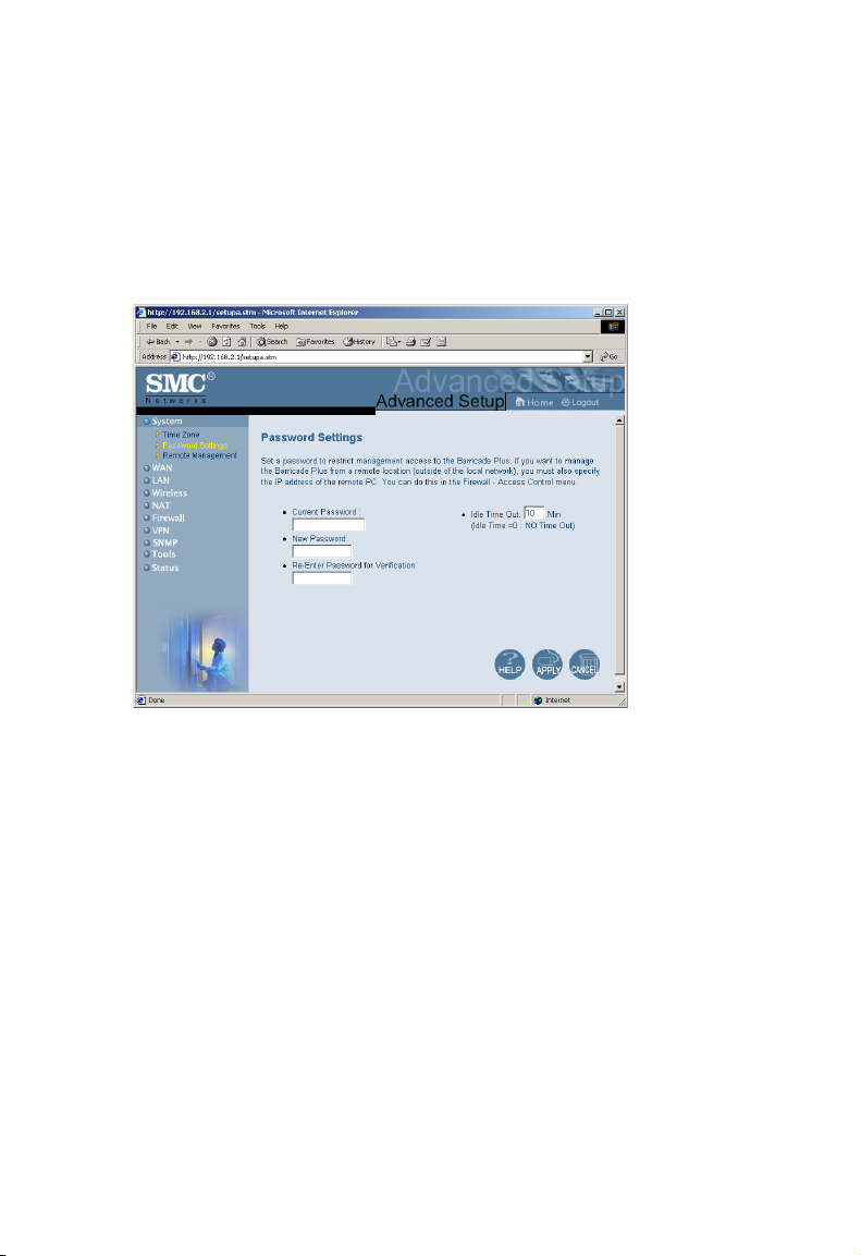
Setting a Password
If this is your first time to access the Wireless Barricade Plus, you should
define a new password, record it and put it in a safe place. From the
“Advanced Setup” menu, select “System” and click on “Password Settings”
and follow the instructions on the screen.
Use this menu to restrict management access based on a specific password.
Anyone can access the “Setup Wizard,” “Advanced Setup” and Help
menus, but you must enter a password to access the configuration options
provided by the “Setup Wizard” and “Advanced Setup” menus. By default,
there is no password. Please assign a password to the Wireless Barricade
Plus as soon as possible, and store it in a safe place.
Passwords can contain from 3–12 alphanumeric characters, and are case
sensitive.
4-12
Page 47
C
ONFIGURING THE WIRELESS BARRICADE PLUS
Note: If your password is lost, or you cannot gain access to the
management interface, press the Reset button on the front panel
(holding it down for at least five seconds) to restore the factory
defaults.
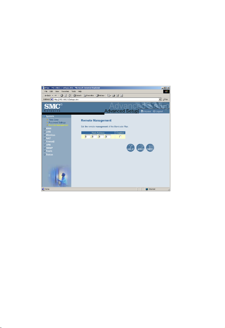
Remote Management
By default, management access is only available to users on your local
network. However, you can also manage the Wireless Barricade Plus from
a remote host by adding the IP address of an administrator to this screen.
Note: If you specify an IP address of 0.0.0.0, any host can manage the
Wireless Barricade Plus. You can also manage the Wireless
Barricade Plus from a remote host by typing
“http://192.168.2.1:8080” in the “Address” field of your Web
browser.
4-13
Page 48

N
ETWORKING AND CLIENT SERVICES
Networking and Client Services
You can use the “Setup Wizard” to change the required settings, or
you can select the basic configuration items you need to change
from the “Setup Wizard” screen.
Use the “Advanced Setup” menu to configure the WAN connection
options, the LAN interface (including TCP/IP parameters for the Wireless
Barricade Plus’ gateway address, DHCP address pool for dynamic client
address allocation), and other advanced services.
WAN Configuration
Specify the WAN connection type required by your Internet
Service Provider, then click “More Configuration” to provide
detailed configuration parameters for the selected connection type.
Specify one of the first three options to configure a WAN connection
through the RJ-45 port (i.e., a connection to an xDSL modem or cable
modem).
4-14
Page 49

C
ONFIGURING THE WIRELESS BARRICADE PLUS
Dynamic IP Address – DHCP
The Host Name is optional, but may be required by some ISPs.
The default MAC address is set to the WAN’s physical interface on
the Wireless Barricade Plus. Use this address when registering for Internet
service, and do not change it unless required by your ISP.
4-15
Page 50

N
ETWORKING AND CLIENT SERVICES
PPP over Ethernet – PPPoE
Enter the PPPoE user name and password assigned by your ISP.
The Service Name is normally optional, but may be required by
some providers.
Specify the value of MTU (Maximum Transmission Unit) for proper
Internet access such as browsing web sites and using E-mail.
(Default: 1492)
Enter the maximum idle time for the Wireless Barricade Plus (in seconds).
4-16
Page 51

C
ONFIGURING THE WIRELESS BARRICADE PLUS
Static IP Address – Fixed IP
If your Internet Service Provider has assigned a fixed address, enter
the assigned address and subnet mask for the Wireless Barricade Plus, then
enter the gateway address of your ISP.
Note: You may need a fixed address if you want to provide Internet
services, such as a Web server or FTP server.
4-17
Page 52

N
ETWORKING AND CLIENT SERVICES
DNS Configuration
Domain Name Servers are used to map an IP address to the equivalent
domain name (e.g., www.smc.com). Your ISP should provide the IP
address for one or more domain name servers. Enter those addresses on
this screen.
4-18
Page 53

C
ONFIGURING THE WIRELESS BARRICADE PLUS
LAN Gateway and DHCP Settings
Configure the gateway address of the Wireless Barricade Plus. To
dynamically assign the IP address for client PCs, enable the DHCP Server,
set the lease time, and then specify the address range. Also remember to
configure all of your client PCs for dynamic address allocation.
Valid IP addresses consist of four numbers, and are separated by periods.
The first three fields are the network portion, and can be from 0–255,
while the last field is the host portion and can be from 1–254. However,
remember not to include the gateway address of the Wireless Barricade
Plus in the client address pool. If you change the pool range, make sure the
first three octets match the gateway’s IP address, i.e., 192.168.2.xxx.
Note: Verify that your IP address pool is from 192.168.2.2 to
192.168.2.254, your subnet mask is 255.255.255.0 and your default
gateway is 192.168.2.1.
4-19
Page 54
N
ETWORKING AND CLIENT SERVICES
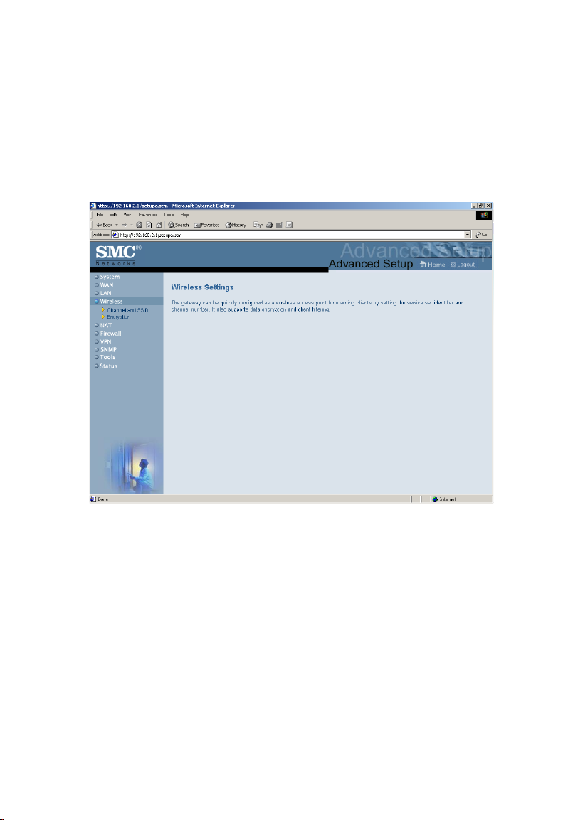
Wireless Configuration
To configure the Wireless Barricade Plus as a wireless access point for
wireless clients (either stationary or roaming), all you need to do is define
the radio channel, the Service Set identifier (SSID), and encryption
options.
4-20
Page 55

C
ONFIGURING THE WIRELESS BARRICADE PLUS
Channel and SSID
You must specify a common radio channel and SSID (Service Set ID) to
be used by the Wireless Barricade Plus and all of your wireless clients. Be
sure you configure all of your clients to the same values.
ESSID: The Service Set ID. This should be set to the same value as other
wireless devices in your network.
Note: The SSID is case sensitive and can consist of up to 32
alphanumeric characters.
Transmission Rate: Set the data rate transmitted from the
Wireless Barricade Plus. The lower the data rate, the longer
the transmission distance. (Default: Fully Automatic)
Basic Rate: Select “All (1, 2, 5.5, 11Mbps)” from the
drop-down list to optimize the data transfer speed for
your network. (Default: 1, 2Mbps)
4-21
Page 56

N
ETWORKING AND CLIENT SERVICES
Channel: The radio channel through which the Wireless Barricade
Plus communicates to PCs in its BSS. (Default: “Auto”)
Note: The available channel settings are limited to local
regulations, which determine the number of channels that
are available.
Encryption
If you are transmitting sensitive data
across wireless channels, you should
enable Wired Equivalent Privacy (WEP)
encryption. Encryption requires you to
use the same set of encryption/decryption keys for the Wireless Barricade
Plus and all of your wireless clients. You can choose between standard
64-bit or the more robust 128-bit encryption keys.
4-22
Page 57

C
ONFIGURING THE WIRELESS BARRICADE PLUS
You can automatically generate encryption keys or you can manually enter
the keys. For automatic 64-bit security, you enter a passphrase that is used
to create four keys (as shown below). The automatic 128-bit security
generates a single key by entering a passphrase.
4-23
Page 58

N
ETWORKING AND CLIENT SERVICES
If you use encryption, configure the same keys used for the Wireless
Barricade Plus on each of your wireless clients. Note that the Wired
Equivalent Privacy (WEP) protects data transmitted between wireless
nodes, but does not protect any transmissions over your wired network or
over the Internet.
4-24
Page 59
C
ONFIGURING THE WIRELESS BARRICADE PLUS
Configuring Client Services
The Wireless Barricade Plus includes a broad range of client services,
including firewall protection, VPN tunneling capability, network address
translation, virtual server, address mapping, DMZ, and restricted Internet
access for specified clients. You can configure these functions by selecting
specific items from the menu on the left of the screen.
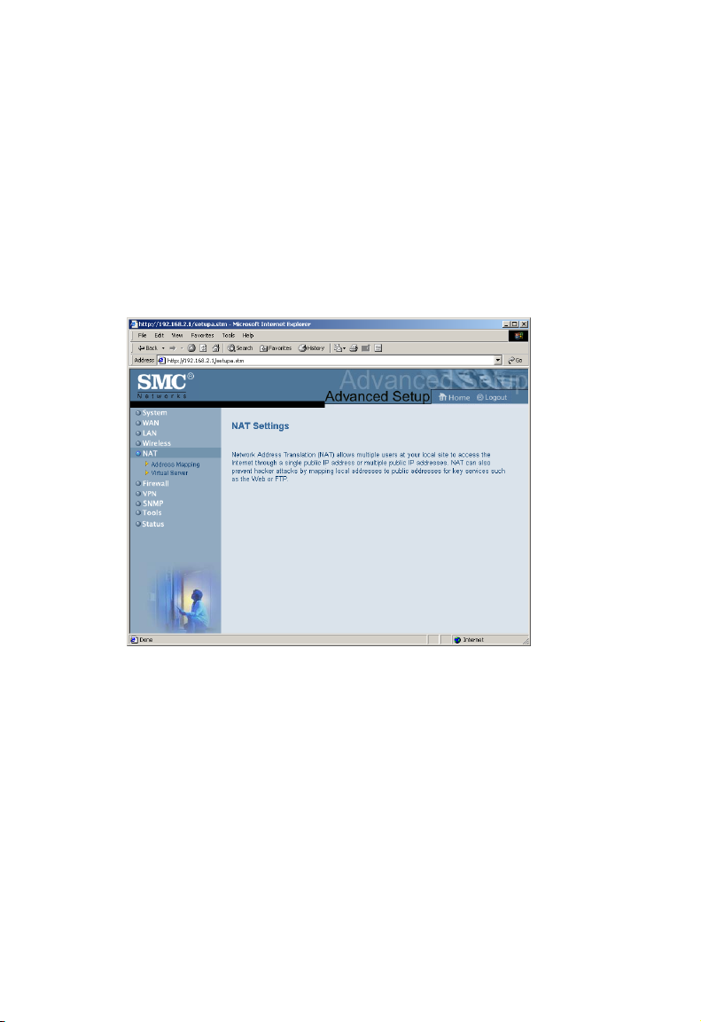
NAT - Network Address Translation
Network Address Translation (NAT) provides multiple Internet
connections using single IP address. If you need multiple connections, use
the following screen to specify the public IP addresses to be opened for
your client users. NAT can also prevent hacker attacks by mapping local
addresses to public addresses for key services such as the Web or FTP.
4-25
Page 60

N
ETWORKING AND CLIENT SERVICES
Address Mapping
Use the “Address Mapping” option to limit the number of public IP
addresses required from the ISP and maintain the privacy and
security of the local network.
4-26
Page 61
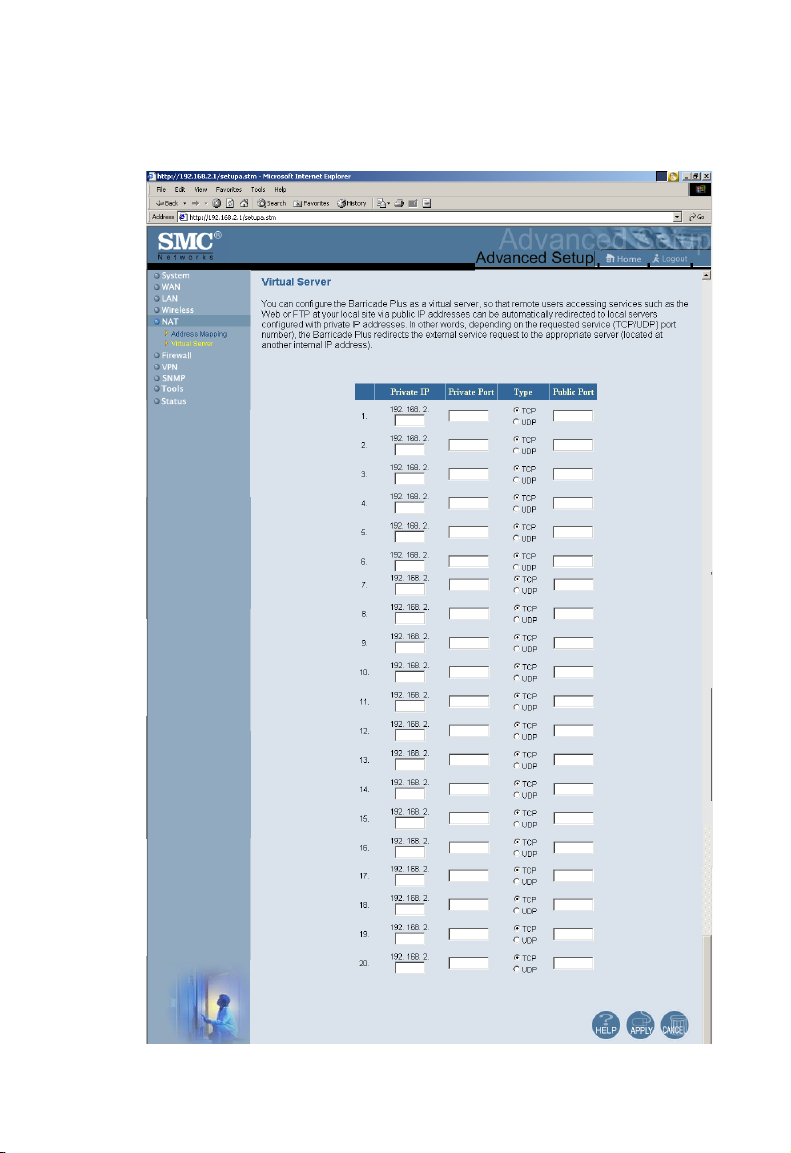
Virtual Server
C
ONFIGURING THE WIRELESS BARRICADE PLUS
4-27
Page 62

N
ETWORKING AND CLIENT SERVICES
If you configure the Wireless Barricade Plus as a virtual server, remote
users accessing services such as Web or FTP at your local site via public IP
addresses can be automatically redirected to local servers configured with
private IP addresses. In other words, depending on the requested service
(TCP/UDP port number), the Wireless Barricade Plus redirects the
external service request to the appropriate server (located at another
internal IP address).
The WAN interface must have a fixed IP address to utilize this
function. For example, if you set Type/Public Port to TCP/80
(HTTP or Web) and the Private IP/Port to 192.168.2.2/80, then all
HTTP request from outside users will be transferred to 192.168.2.2.
Therefore, by just entering the IP Address provided by the ISP,
Internet users can access the service they need at the local address
to which you redirect them.
Some of the more common TCP service ports include:
HTTP: 80, FTP: 21, Telnet: 23 and POP3: 110.
4-28
Page 63
C
ONFIGURING THE WIRELESS BARRICADE PLUS
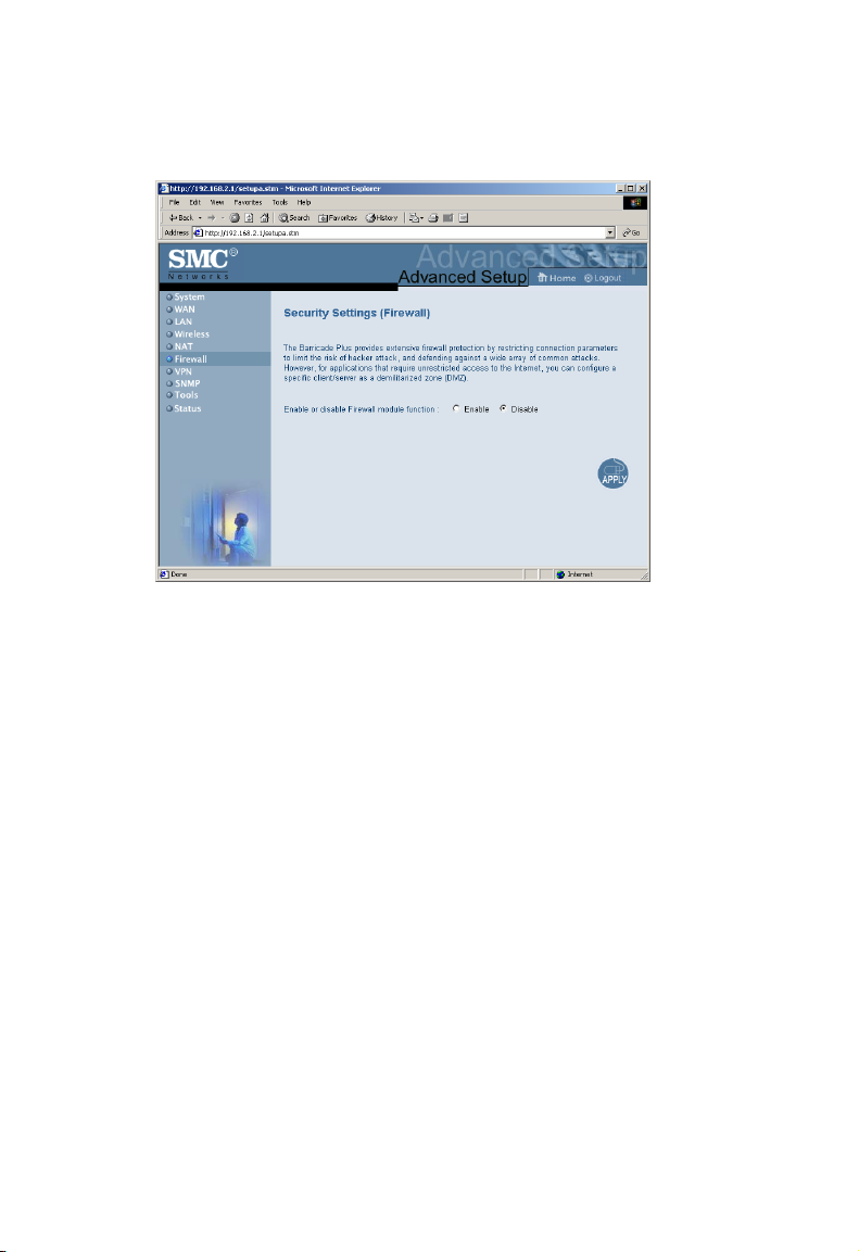
Firewall Protection
The Wireless Barricade Plus’ firewall can provide the access control of
connected client PCs, block common hacker attacks, including IP
Spoofing, Land Attack, Ping of Death, IP with zero length, Smurf
Attack, UDP port loopback, Snork Attack, TCP null scan, and TCP
SYN flooding. The firewall does not significantly affect system
performance, so we advise setting it enabled to protect your
network users by selecting “Enable” on the screen.
Note: When you select the “Enable” radio button of the “Enable
or disable Firewall module function” field, be sure to press
the “APPLY” button.
4-29
Page 64

N
ETWORKING AND CLIENT SERVICES
Access Control
Using this option allows you to specify different privileges for the
client PCs (up to 32 computers).
The following items are included in the “Access Control” screen:
Field Description
Normal Filtering Table Displays the IP address and filtering status of
the connected client PC
MAC Filtering Table Displays the MAC address of the client PC
4-30
Page 65

C
ONFIGURING THE WIRELESS BARRICADE PLUS
Note: Click on “Add PC” and define the appropriate settings for client
PC services (as shown in the following screen).
4-31
Page 66

N
ETWORKING AND CLIENT SERVICES
URL Blocking
Using the above screen to block access to the Web sites specified in the
table.
4-32
Page 67

C
ONFIGURING THE WIRELESS BARRICADE PLUS
Schedule Rule
You can filter Internet access for local clients based on the “Rule
Name,” and time of day.
4-33
Page 68

N
ETWORKING AND CLIENT SERVICES
1. Click on “Add Schedule Rule”
2. Define the appropriate settings for a schedule rule (as shown in the
following screen).
3. Click “OK” and then the “APPLY” button to save your settings. (as
shown on previous page)
4-34
Page 69

Intrusion Detection
C
ONFIGURING THE WIRELESS BARRICADE PLUS
4-35
Page 70

N
ETWORKING AND CLIENT SERVICES
The Intrusion Detection feature of the Wireless Barricade Plus limits the
access of the incoming traffic from the WAN port. When the SPI feature
is turned on, all the incoming packets will be blocked unless certain types
of traffic types are checked by the users. When the user checkes certain
types of traffic, only the particular type of traffic initiated from the Internal
LAN will be allowed. For example, if the user only checks “FTP service”
from the Stateful Packet Inspection heading, all the incoming traffic will be
blocked except the FTP connection initiated from the local LAN.
• Stateful Packet Inspection
This option allows you to select different application types that are using
dynamic port numbers. If you need to use the Stateful Packet Inspection
(SPI) for blocking packets, check the radio button in the “Enable SPI and
Anti-DoS firewall protection” field and then check the inspection type that
you need, such as Packet Fragmentation, TCP Connection, UDP Session,
FTP Service, H.323 Service and TFTP Service.
• Hacker Prevention Feature
The Wireless Barricade Plus’ firewall inspects packets at the application
layer, and maintains TCP and UDP session information, including
timeouts and number of active sessions, provides the ability to detect and
prevent certain types of network attacks such as DoS attacks.
Network attacks that deny access to a network device are called
denial-of-service (DoS) attacks. Denials of Service (DoS) attacks are aimed
at devices and networks with a connection to the Internet. Their goal is
not to steal information, but to disable a device or network so users no
longer have access to network resource.
4-36
Page 71

C
ONFIGURING THE WIRELESS BARRICADE PLUS
By using the above inspected information and timeout/threshold critieria,
the Wireless Barricade Plus provides the following DoS attack preventions:
Ping of Death (Ping flood) attack, SYN flood attack, IP fragment attack
(Teardrop Attack), Brute-force attack, Land Attack, IP Spoofing attack, IP
with zero length, TCP null scan (Port Scan Attack), UDP port loopback,
Snork Attack etc..
Note: The firewall does not significantly affect system performance, so
we advise enabling the prevention features to protect your network
users.
• When hackers attempt to enter your network, we can alert you by e-mail
Enter your E-mail address for alerting hacker access.
Specify your E-mail servers, user name and password.
• Connection Policy
Enter the appropriate values for TCP/UDP sessions
• DoS Criteria and Port Scan Criteria
Setup DoS and port scan criteria in the spaces provided.
4-37
Page 72

N
ETWORKING AND CLIENT SERVICES
DMZ (Demilitarized Zone)
If you have a client PC that cannot run an Internet application
properly from behind the firewall, then you can open the client up
to unrestricted two-way Internet access. Enter the IP address of a
DMZ host to this screen. Adding a client to the DMZ (Demilitarized
Zone) may expose your local network to a variety of security risks,
so only use this option as a last resort.
4-38
Page 73

C
ONFIGURING THE WIRELESS BARRICADE PLUS
Virtual Private Networks (VPN) Tunnel
VPN provides a flexible and secure network to the authenticate users
through IPsec (IP Security) and PPTP (Point-to-Point Tunneling Protocol)
sessions.
4-39
Page 74
N
ETWORKING AND CLIENT SERVICES
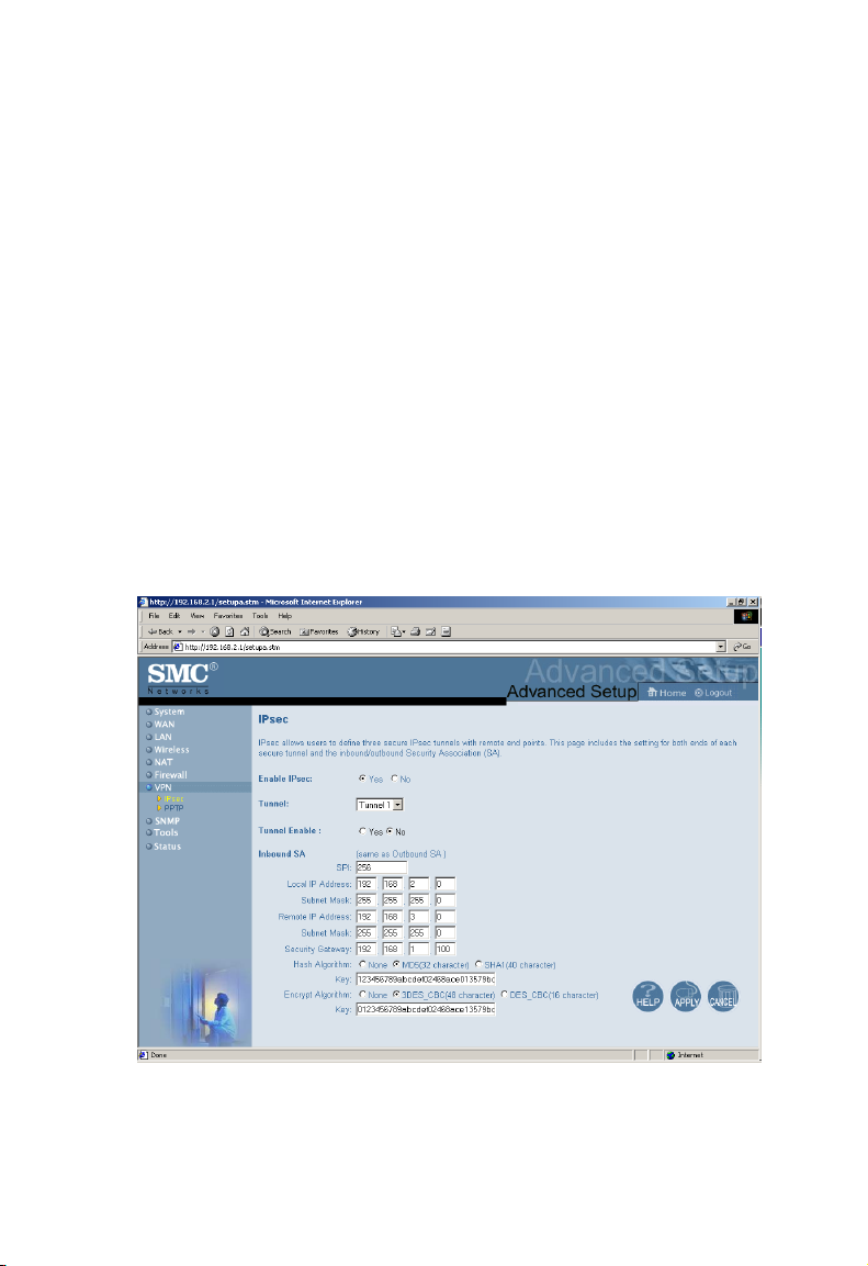
IPsec
IPsec is a set of protocols that offers more secure security services in the
extranet VPNs.
On the IPsec screen, select “Yes” in the “Enable IPsec” field for using the
IPsec service, and choose the appropriate tunnel (Tunnel 1 - 3) as required.
Then you have to define the authentication algorithms of the Security
Association (SA) by entering appropriate values in the “Inbound SA” and
“Outbound SA” fields for using IPsec security control.
Notes: 1. Besure the two sides of the VPN tunnel have the same security
information.
2. Provide the “Remote IP Address” to remotely log on the
network.
4-40
Page 75
C
ONFIGURING THE WIRELESS BARRICADE PLUS
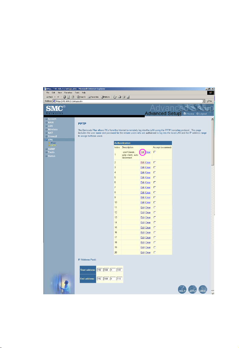
PPTP
Point-to-Point Tunneling Protocol (PPTP) allows the secure remote access
over the Internet by simply dialing in a local point provided by an ISP. The
following screen display the account information of the authorized remote
users and the IP address range to assign to those users
4-41
Page 76

N
ETWORKING AND CLIENT SERVICES
Click “Edit” on the screen to setup a PPTP session.
Using the above screen allows client PCs to establish a normal PPTP
session and provides hassle-free configuration of the PPTP client on each
client PC.
4-42
Page 77
C
ONFIGURING THE WIRELESS BARRICADE PLUS
SNMP
Use the SNMP configuration screen to display and modify parameters for
the Simple Network Management Protocol (SNMP). A computer attached
to the network, called a Network Management Station (NMS), can be used
to access this information. Access rights to the agent are controlled by
community strings. To communicate with the Wireless Barricade Plus, the
NMS must first submit a valid community string for authentication. The
options for configuring community strings and related trap functions are
described in the following sections.
4-43
Page 78
N
ETWORKING AND CLIENT SERVICES
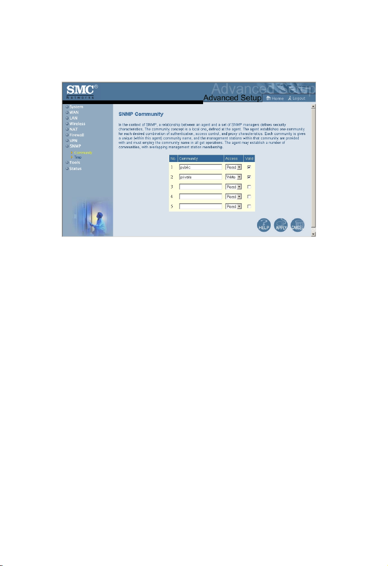
Community
Community: A community name authorized for management
access.
Access: Management access is restricted to Read only or Read/
Write.
Valid: Sets administrative status of entry to enabled or
disabled.
Note: Up to 5 community names may be entered.
4-44
Page 79
C
ONFIGURING THE WIRELESS BARRICADE PLUS
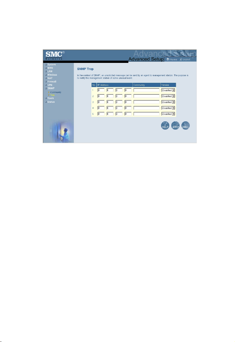
Trap
IP Address: IP address of the trap manager.
Community: A community specified for trap management.
Version: Sets trap status of entry to disabled, or enabled with
V1 or V2c.
4-45
Page 80

N
ETWORKING AND CLIENT SERVICES
Tools
You can use the “Tools” menu to restore factory settings, update
firmware, or reboot the Wireless Barricade Plus.
4-46
Page 81

C
ONFIGURING THE WIRELESS BARRICADE PLUS
Configuration Tools
The “Backup” option allows you to save your Wireless Barricade Plus’
configuration to a file named config.bin on your PC. You can then
click on the “Restore” radio button to restore the saved backup
configuration file. Selecting the “Restore to Factory Defaults” can
restore the factory settings.
4-47
Page 82

N
ETWORKING AND CLIENT SERVICES
Firmware Upgrade
Use this screen to update the latest firmware using a file provided by
SMC.
Note: For latest firmware version information, visit SMC’s Web
site at http://www.smc.com.
4-48
Page 83

C
ONFIGURING THE WIRELESS BARRICADE PLUS
Reset
If the Wireless Barricade Plus stops responding, you can click on the
“Apply” button to refresh the gateway. The saved configurations of the
Wireless Barricade Plus will not be changed back to factory default settings
after resetting the gateway.
Note: If you use the reset button on the rear panel, the Wireless
Barricade Plus performs a power reset and restores the factory
settings.
4-49
Page 84

N
ETWORKING AND CLIENT SERVICES
Status
You can use the following screen to display WAN/LAN connection status,
firmware and hardware version numbers, as well as information on all
DHCP clients connected to your network.
4-50
Page 85

C
ONFIGURING THE WIRELESS BARRICADE PLUS
The following items are included in this screen:
Field Description
INTERNET Displays WAN connection type and status.
GATEWAY Displays system IP settings, as well as DHCP,
INFORMATION Displays the number of attached clients, the
Release Click on this button to disconnect from the
Renew Click on this button to reconnect to the
Security Log Displays any illegal attempts to access your
DHCP Client Log Displays information on all DHCP clients on
NAT, PPTP Client and PPTP Server Firewall.
firmware versions, the physical MAC address
for each media interface, as well as the
hardware version and serial number.
Internet.
Internet via cable/DSL modem.
network.
your network.
4-51
Page 86

N
ETWORKING AND CLIENT SERVICES
4-52
Page 87

C
HAPTER
C
ONFIGURING
C
LIENT
TCP/IP
If you have not previously installed the TCP/IP protocol on your
client PCs, refer to the following section. If you need information on
how to configure a TCP/IP address on a PC, refer to “Setting TCP/IP to
Work with the Wireless Barricade Plus” on page 5-5.
Installing TCP/IP Protocol in Your PC
Windows 95/98/ME
1. Click the “Start” button and choose “Settings,” then click
“Control Panel.”
2. Double click the “Network” icon and select the “Configuration”
tab in the Network window.
5
3. Click the “Add” button to add the network component to your
PC.
4. Double click “Protocol” to add the TCP/IP protocol.
5-1
Page 88

I
NSTALLING
TCP/IP P
5. Select the “Microsoft” item in the manufacturers list. And choose
“TCP/IP” in the Network Protocols. Click the “OK” button to
return to the Network window.
6. The TCP/IP protocol will be listed in the Network window.
Click “OK” to complete the install procedure and restart your PC
to enable the TCP/IP protocol.
ROTOCOL IN YOUR
PC
5-2
Page 89

C
ONFIGURING CLIENT
Windows 2000
1. Click the “Start” button and choose “Settings,” then click
“Control Panel.”
2. Double click the “Network and Dial-up Connections” icon, then
“Local Area Connection” icon, and press the “Properties” button
in the “General” tab.
3. Click the “install...” button to add the network component to your
PC.
4. Double click on “Protocol” to add the TCP/IP protocol.
TCP/IP
5-3
Page 90
I
NSTALLING
TCP/IP P
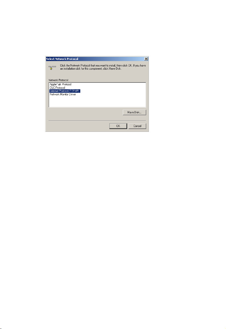
5. Choose “Internet Protocol (TCP/IP)” in the Network Protocols.
Click the “OK” button to return to the Network window.
6. The TCP/IP protocol will be listed in the Network window.
Click “OK” to complete the install procedure.
ROTOCOL IN YOUR
PC
5-4
Page 91

C
ONFIGURING CLIENT
TCP/IP
Setting TCP/IP to Work with the Wireless Barricade Plus
Windows 95/98/ME
1. Click the “Start” button and choose “Settings,” then click
“Control Panel.”
2. Double click the “Network” icon. Select the TCP/IP line that has
been assigned to your network card in the “Configuration” tab of
the Network window.
3. Click the “Properties” button to set the TCP/IP protocol for the
Wireless Barricade Plus.
4. You can dynamically assign TCP/IP address settings to a client,
or you can manually configure a client with address settings to
meet your specific network requirements. (Note that the default
IP address of the Wireless Barricade Plus is 192.168.2.1.)
5-5
Page 92

S
ETTING
TCP/IP TO W
ORK WITH THE WIRELESS BARRICADE PLUS
Windows 2000
1. Click the “Start” button and choose “Settings,” then click
“Control Panel.”
2. Double click the “Network and Dial-up Connections” icon, then
“Local Area Connection” icon, and press the “Properties” button
in the “General” tab.
3. Select the TCP/IP line that has been assigned to your network
card in the “Local Area Connection Properties” window.
4. Click the “Properties” button to set the TCP/IP protocol for the
Wireless Barricade Plus.
5. You can dynamically assign TCP/IP address settings to a client,
or you can manually configure a client with address settings to
meet your specific network requirements. (Note that the default
IP address of the Wireless Barricade Plus is 192.168.2.1.)
5-6
Page 93
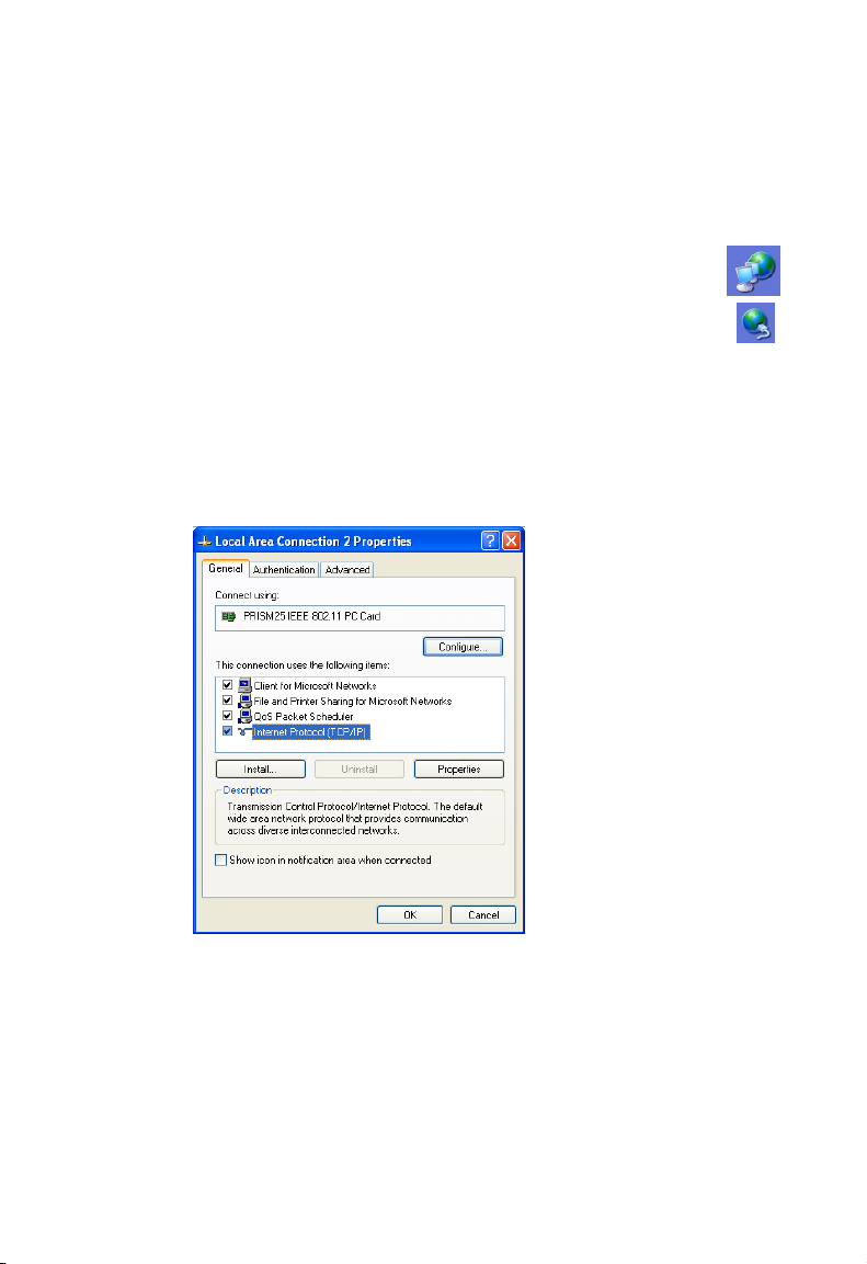
C
ONFIGURING CLIENT
Windows XP
1. Click the “start” button and choose “Control Panel.”
2. Select the “Network and Internet Connections” icon,
then click the “Network Connections” icon, and double
click on the “LAN or High-Speed Internet.”
3. Press the “Properties” button in the “General” tab.
4. Select the TCP/IP line that has been assigned to your network
card in the “Local Area Connection Properties” window.
5. Click the “Properties” button to set the TCP/IP protocol for the
Wireless Barricade Plus.
TCP/IP
6. You can dynamically assign TCP/IP address settings to a client,
or you can manually configure a client with address settings to
meet your specific network requirements. (Note that the default
IP address of the Wireless Barricade Plus is 192.168.2.1.)
5-7
Page 94
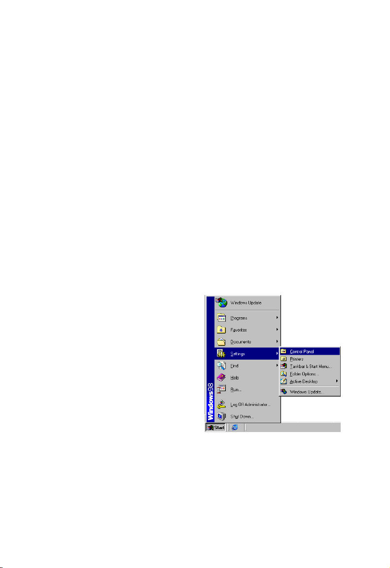
S
ETTING
TCP/IP TO W
ORK WITH THE WIRELESS BARRICADE PLUS
Configuring Your Computer with Windows 95/98/ME
You may find that the instructions here do not exactly match your
version of Windows. This is because these steps and screenshots were
created from Windows 98. Windows 95 and Windows Millennium
Edition are very similar, but not identical, to Windows 98.
Step 1. Configure TCP/IP Settings
After you have completed the hardware setup by connecting your devices,
you need to configure your computer to connect to your Wireless
Barricade Plus. You need to determine how your ISP issues your IP
address. Many ISPs issue these numbers automatically using a
networking technology known as Dynamic Host Configuration
Protocol, or DHCP. Other ISPs will specify your IP address and
associated numbers, which you must enter manually. This is also
known as a static IP address. How your ISP assigns your IP address
determines how you will configure your computer.
1. From the Windows
desktop, click the "Start"
button. Choose "Settings,"
then click "Control Panel."
5-8
Page 95
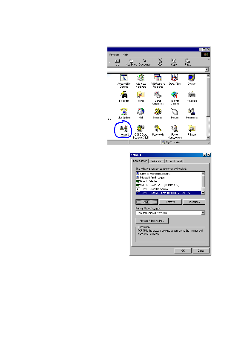
2. From "Control
Panel," double-click
the "Network" icon.
3. In the "Network"
window, under the
"Configuration" tab,
double-click the "TCP/IP"
entry that is listed with
your network card.
C
ONFIGURING CLIENT
TCP/IP
5-9
Page 96

S
ETTING
TCP/IP TO W
4. Select the "IP Address" tab.
If "Obtain an IP address
automatically" is already
selected, your computer is
already configured for DHCP.
Click "Cancel" to close each
window, and skip to Step 2
"Disable HTTP Proxy."
ORK WITH THE WIRELESS BARRICADE PLUS
5. Locate your IP address and
Subnet Mask. Record them
in the spaces provided
below.
6. Click the "Gateway" tab and
record the numbers listed
under "Installed gateways."
5-10
Page 97

C
ONFIGURING CLIENT
TCP/IP
7. Click the "DNS
Configuration" tab. Locate
the DNS servers listed under
"DNS Server Search Order."
Record the listed addresses.
8. After writing down your
settings, check to make sure
you have recorded them
correctly. Click the "IP
Address" tab and then click
"Obtain an IP address
automatically." Click OK.
9. Windows may need
your Windows 95/98/
ME CD to copy some
files. After it finishes
copying, it will then
prompt you to restart
your system. Click "Yes" and your computer will shut down and
restart.
TCP/IP Configuration Setting
IP Address ____.____.____.____
Subnet Mask ____.____.____.____
Primary DNS Server ____.____.____.____
Secondary DNS Server ____.____.____.____
Default Gateway ____.____.____.____
Step 2. Disable HTTP Proxy
You will need to verify that the "HTTP Proxy" feature of your Web
browser is disabled. This is so that your Web browser will be able to
view the configuration pages inside your Wireless Barricade Plus. The
following steps are for Internet Explorer and for Netscape.
Determine which browser you use and follow the appropriate steps.
5-11
Page 98

S
ETTING
TCP/IP TO W
Internet Explorer
1. Open Internet Explorer
and click the stop button.
Click "Tools," then
"Internet Options."
2. In the "Internet
Options" window click
the "Connections" tab.
Next, click the "LAN
Settings..." button.
3. Clear all the
checkboxes.
ORK WITH THE WIRELESS BARRICADE PLUS
4. Click "OK," and then
click "OK" again to close
the "Internet Options"
window.
5-12
Page 99

C
ONFIGURING CLIENT
Netscape
1. Open Netscape and click the stop
button. Click "Edit," then click
"Preferences..."
2. In the
"Preferences"
window, under
"Category"
double-click
"Advanced,"
then click
"Proxies." Select
"Direct
connection to
the Internet."
Click "OK."
3. Repeat these
steps for each Windows 95/98/Me computer connected to your
Wireless Barricade Plus.
TCP/IP
Step 3. Obtain IP Settings from Your Wireless Barricade Plus
Now that you have configured your computer to connect to your Wireless
Barricade Plus, it needs to obtain new network settings. By releasing any
old IP settings and renewing them with settings from your Wireless
Barricade Plus, you will also verify that you have configured your computer
correctly.
5-13
Page 100

S
ETTING
TCP/IP TO W
1. Click "Start," then "Run..."
2. Type "WINIPCFG" and
click "OK." It may take a
minute or two for the "IP
Configuration" window to
appear.
3. From the drop-down menu,
select your network card.
Click "Release" and then
"Renew." Verify that your
IP address is now
192.168.2.xxx, your Subnet
Mask is 255.255.255.0 and
your Default Gateway is
192.168. 2.1. These values
confirm that your Wireless Barricade Plus is functioning. Click "OK"
to close the "IP Configuration" window.
ORK WITH THE WIRELESS BARRICADE PLUS
5-14
 Loading...