

Page 1

TigerSwitch 10/100
Stackable Fast Ethernet Switch
◆ 24 10BASE-T/100BASE-TX RJ-45 ports
◆ Auto MDI/MDI-X support on all ports
◆ Optional 100BASE-FX or 1000BASE-X modules
◆ Optional stack module for linking up to 16 units
◆ 8.8 Gbps of aggregate switch bandwidth
◆ LACP port trunking support
◆ Port mirroring for non-intrusive analysis
◆ Port security
◆ Full support for IEEE 802.1Q VLANs with GVRP
◆ IP Multicasting with IGMP Snooping
◆ Manageable via console, Web, SNMP/RMON
Installation Guide
SMC6624M
Page 2

Page 3

TigerSwitch 10/100
Installation Guide
From SMC’s Tiger line of feature-rich workgroup LAN solutions
6 Hughes
Irvine, CA 92618
Phone: (949) 707-2400
August 2001
Pub. # 150000001400A R01
Page 4

Information furnished by SMC Networks, Inc. (SMC) is believed to be accurate and reliable. However, no responsibility is
assumed by SMC for its use, nor for any infringements of patents or other rights of third parties which may result from its
use. No license is granted by implication or otherwise under any patent or patent rights of SMC. SMC reserves the right to
change specifications at any time without notice.
Copyright © 2001 by
SMC Networks, Inc.
6 Hughes
Irvine, CA 92618
All rights reserved. Printed in Taiwan
Trademarks:
SMC is a registered trademark; and EZ Switch, TigerStack and TigerSwitch are trademarks of SMC Networks, Inc. Other product and
company names are trademarks or registered trademarks of their respective holders.
Page 5

L
IMITED
Limited Warranty Statement: SMC Networks, Inc. (“SMC”) warrants its products to be free from defects in
workmanship and materials, under normal use and service, for the applicable warranty term. All SMC products carry a
standard 90-day limited warranty from the date of purchase from SMC or its Authorized Reseller. SMC may, at its own
discretion, repair or replace any product not operating as warranted with a similar or functionally equivalent product, during
the applicable warranty term. SMC will endeavor to repair or replace any product returned under warranty within 30 days of
receipt of the product.
The standard limited warranty can be upgraded to a Limited Lifetime* warranty by registering new products within 30 days
of purchase from SMC or its Authorized Reseller. Registration can be accomplished via the enclosed product registration
card or online via the SMC web site. Failure to register will not affect the standard limited warranty. The Limited Lifetime
warranty covers a product during the Life of that Product, which is defined as the period of time during which the product is
an “Active” SMC product. A product is considered to be “Active” while it is listed on the current SMC price list. As new
technologies emerge, older technologies become obsolete and SMC will, at its discretion, replace an older product in its
product line with one that incorporates these newer technologies. At that point, the obsolete product is discontinued and is
no longer an “Active” SMC product. A list of discontinued products with their respective dates of discontinuance can be
found at:
http://www.smc.com/smc/pages_html/support.html.
All products that are replaced become the property of SMC. Replacement products may be either new or reconditioned. Any
replaced or repaired product carries either a 30-day limited warranty or the remainder of the initial warranty, whichever is
longer. SMC is not responsible for any custom software or firmware, configuration information, or memory data of
Customer contained in, stored on, or integrated with any products returned to SMC pursuant to any warranty. Products
returned to SMC should have any customer-installed accessory or add-on components, such as expansion modules, removed
prior to returning the product for replacement. SMC is not responsible for these items if they are returned with the product.
Customers must contact SMC for a Return Material Authorization number prior to returning any product to SMC. Proof of
purchase may be required. Any product returned to SMC without a valid Return Material Authorization (RMA) number
clearly marked on the outside of the package will be returned to customers at customer’s expense. For warranty claims within
North America, please call our toll-free customer support number at (800) 762-4968. Customers are responsible for all
shipping charges from their facility to SMC. SMC is responsible for return shipping charges from SMC to customer.
WARRANTIES EXCLUSIVE: IF AN SMC PRODUCT DOES NOT OPERATE AS WARRANTED ABOVE,
CUSTOMER’S SOLE REMEDY SHALL BE REPAIR OR REPLACEMENT OF THE PRODUCT IN QUESTION, AT
SMC’S OPTION. THE FOREGOING WARRANTIES AND REMEDIES ARE EXCLUSIVE AND ARE IN LIEU OF
ALL OTHER WARRANTIES OR CONDITIONS, EXPRESS OR IMPLIED, EITHER IN FACT OR BY OPERATION
OF LAW, STATUTORY OR OTHERWISE, INCLUDING WARRANTIES OR CONDITIONS OF
MERCHANTABILITY AND FITNESS FOR A PARTICULAR PURPOSE. SMC NEITHER ASSUMES NOR
AUTHORIZES ANY OTHER PERSON TO ASSUME FOR IT ANY OTHER LIABILITY IN CONNECTION WITH
THE SALE, INSTALLATION, MAINTENANCE OR USE OF ITS PRODUCTS. SMC SHALL NOT BE LIABLE
UNDER THIS WARRANTY IF ITS TESTING AND EXAMINATION DISCLOSE THE ALLEGED DEFECT IN
THE PRODUCT DOES NOT EXIST OR WAS CAUSED BY CUSTOMER’S OR ANY THIRD PERSON’S MISUSE,
NEGLECT, IMPROPER INSTALLATION OR TESTING, UNAUTHORIZED ATTEMPTS TO REPAIR, OR ANY
OTHER CAUSE BEYOND THE RANGE OF THE INTENDED USE, OR BY ACCIDENT, FIRE, LIGHTNING, OR
OTHER HAZARD.
LIMITATION OF LIABILITY: IN NO EVENT, WHETHER BASED IN CONTRACT OR TORT (INCLUDING
NEGLIGENCE), SHALL SMC BE LIABLE FOR INCIDENTAL, CONSEQUENTIAL, INDIRECT, SPECIAL, OR
PUNITIVE DAMAGES OF ANY KIND, OR FOR LOSS OF REVENUE, LOSS OF BUSINESS, OR OTHER
FINANCIAL LOSS ARISING OUT OF OR IN CONNECTION WITH THE SALE, INSTALLATION,
W
ARRANTY
i
Page 6

L
IMITED WARRANTY
MAINTENANCE, USE, PERFORMANCE, FAILURE, OR INTERRUPTION OF ITS PRODUCTS, EVEN IF SMC OR
ITS AUTHORIZED RESELLER HAS BEEN ADVISED OF THE POSSIBILITY OF SUCH DAMAGES.
SOME STATES DO NOT ALLOW THE EXCLUSION OF IMPLIED WARRANTIES OR THE LIMITATION OF
INCIDENTAL OR CONSEQUENTIAL DAMAGES FOR CONSUMER PRODUCTS, SO THE ABOVE LIMITATIONS
AND EXCLUSIONS MAY NOT APPLY TO YOU. THIS WARRANTY GIVES YOU SPECIFIC LEGAL RIGHTS,
WHICH MAY VARY FROM STATE TO STATE. NOTHING IN THIS WARRANTY SHALL BE TAKEN TO AFFECT
YOUR STATUTORY RIGHTS.
* SMC will provide warranty service for one year following discontinuance from the active SMC price list. Under the limited
lifetime warranty, internal and external power supplies, fans, and cables are covered by a standard one-year warranty from date
of purchase.
SMC Networks, Inc.
6 Hughes
Irvine, CA 92618
ii
Page 7

C
OMPLIANCES
FCC - Class A
This equipment generates, uses, and can radiate radio frequency energy and, if not installed and used in accordance with the instruction
manual, may cause interference to radio communications. It has been tested and found to comply with the limits for a Class A computing
device pursuant to Subpart B of Part 15 of FCC Rules, which are designed to provide reasonable protection against such interference when
operated in a commercial environment. Operation of this equipment in a residential area is likely to cause interference, in which case the
user, at his own expense, will be required to take whatever measures may be required to correct the interference. You are cautioned that
changes or modifications not expressly approved by the party responsible for compliance could void your authority to operate the
equipment.
You may use unshielded twisted-pair (UTP) cable for RJ-45 connections—Category 3 or greater for 10 Mbps connections and Category 5
for 100 Mbps connections. Use 50/125 or 62.5/125 micron multimode fiber optic cable for SC or ST-type connections.
Warnin gs :1. Wear an anti-static wrist strap or take other suitable measures to prevent electrostatic discharge when handling this
equipment.
2. When connecting this hub to a power outlet, connect the field ground lead on the tri-pole power plug to a valid earth ground
line to prevent electrical hazards.
Industry Canada - Class A
This digital apparatus does not exceed the Class A limits for radio noise emissions from digital apparatus as set out in the interference-causing
equipment standard entitled “Digital Apparatus,” ICES-003 of the Department of Communications.
Cet appareil numérique respecte les limites de bruits radioélectriques applicables aux appareils numériques de Classe A prescrites dans la
norme sur le matériel brouilleur: “Appareils Numériques,” NMB-003 édictée par le ministère des Communications.
Japan VCCI Class A
EC Conformance Declaration - Class A
SMC contact for these products in Europe is:
SMC Networks Europe,
Edificio Conata II,
Calle Fructuós Gelabert 6-8, 2
08970 - Sant Joan Despí,
Barcelona, Spain.
This information technology equipment complies with the requirements of the Council Directive 89/336/EEC on the Approximation of
the laws of the Member States relating to Electromagnetic Compatibility and 73/23/EEC for electrical equipment used within certain
voltage limits and the Amendment Directive 93/68/EEC. For the evaluation of the compliance with these Directives, the following
standards were applied:
RFI Emission: • Limit class A according to EN 55022:1998
• Limit class A for harmonic current emission according to EN 61000-3-2/1995
• Limitation of voltage fluctuation and flicker in low-voltage supply system according to EN 61000-3-3/1995
Immunity: • Product family standard according to EN 55024:1998
o
, 4a,
iii
Page 8

C
OMPLIANCES
• Electrostatic Discharge according to EN 61000-4-2:1995 (Contact Discharge: ±4 kV, Air Discharge: ±8 kV)
• Radio-frequency electromagnetic field according to EN 61000-4-3:1996
(80 - 1000 MHz with 1 kHz AM 80% Modulation: 3 V/m)
• Electrical fast transient/burst according to EN 61000-4-4:1995
(AC/DC power supply: ±1 kV, Data/Signal lines: ±0.5 kV)
• Surge immunity test according to EN 61000-4-5:1995
(AC/DC Line to Line: ±1 kV, AC/DC Line to Earth: ±2 kV)
• Immunity to conducted disturbances, Induced by radio-frequency fields: EN 61000-4-6:1996
(0.15 - 80 MHz with 1 kHz AM 80% Modulation: 3 V/m)
• Power frequency magnetic field immunity test according to EN 61000-4-8:1993
(1 A/m at frequency 50 Hz)
• Voltage dips, short interruptions and voltage variations immunity test according to EN 61000-4-11:1994
(>95% Reduction @10 ms, 30% Reduction @500 ms, >95% Reduction @5000 ms)
LVD: • EN 60950 (A1/1992; A2/1993; A3/1993; A4/1995; A11/1997)
Taiwan BSMI Class A
Australia AS/NZS 3548 (1995) - Class A
SMC contact for products in Australia is:
SMC Communications Pty. Ltd.
Suite 18, 12 Tryon Road,
Lindfield NSW2070,
Phone: 61-2-94160437
Fax: 61-2-94160474
iv
Page 9
C
OMPLIANCES
Safety Compliance
Warning: Fiber Optic Port Safety
CLASS I
LASER DEVICE
Avertissment: Ports pour fibres optiques - sécurité sur le plan optique
DISPOSITIF LASER
DE CLASSE I
Warnhinweis: Faseroptikanschlüsse - Optische Sicherheit
LASERGER
DER KLASSE I
Underwriters Laboratories Compliance Statement
Important! Before making connections, make sure you have the correct cord set. Check it (read the label on the cable) against the
following:
Operating Voltage Cord Set Specifications
120 Volts UL Listed/CSA Certified Cord Set
240 Volts (Europe only) Cord Set with H05VV-F cord having three conductors with
When using a fiber optic port, never look at the transmit laser while it is powered on. Also, never look directly at
the fiber TX port and fiber cable ends when they are powered on.
Ne regardez jamais le laser tant qu'il est sous tension. Ne regardez jamais directement le port TX (Transmission) à
fibres optiques et les embouts de câbles à fibres optiques tant qu'ils sont sous tension.
Niemals ein Übertragungslaser betrachten, während dieses eingeschaltet ist. Niemals direkt auf den
ÄT
Faser-TX-Anschluß und auf die Faserkabelenden schauen, während diese eingeschaltet sind.
Minimum 18 AWG
Type SVT or SJT three conductor cord
Maximum length of 15 feet
Parallel blade, grounding type attachment plug rated 15A, 125V
minimum diameter of 0.75 mm
IEC-320 receptacle
Male plug rated 10A, 250V
2
The unit automatically matches the connected input voltage. Therefore, no additional adjustments are necessary when connecting it to any
input voltage within the range marked on the rear panel.
v
Page 10

C
OMPLIANCES
Wichtige Sicherheitshinweise (Germany)
1. Bitte lesen Sie diese Hinweise sorgfältig durch.
2. Heben Sie diese Anleitung für den späteren Gebrauch auf.
3. Vor jedem Reinigen ist das Gerät vom Stromnetz zu trennen. Verwenden Sie keine Flüssigoder Aerosolreiniger. Am besten eignet sich
ein angefeuchtetes Tuch zur Reinigung.
4. Die Netzanschlu ßsteckdose soll nahe dem Gerät angebracht und leicht zugänglich sein.
5. Das Gerät ist vor Feuchtigkeit zu schützen.
6. Bei der Aufstellung des Gerätes ist auf sicheren Stand zu achten. Ein Kippen oder Fallen könnte Beschädigungen hervorrufen.
7. Die Belüftungsöffnungen dienen der Luftzirkulation, die das Gerät vor Überhitzung schützt. Sorgen Sie dafür, daß diese Öffnungen
nicht abgedeckt werden.
8. Beachten Sie beim Anschluß an das Stromnetz die Anschlußwerte.
9. Verlegen Sie die Netzanschlußleitung so, daß niemand darüber fallen kann. Es sollte auch nichts auf der Leitung abgestellt werden.
10. Alle Hinweise und Warnungen, die sich am Gerät befinden, sind zu beachten.
11. Wird das Gerät über einen längeren Zeitraum nicht benutzt, sollten Sie es vom Stromnetz trennen. Somit wird im Falle einer
Überspannung eine Beschädigung vermieden.
12. Durch die Lüftungsöffnungen dürfen niemals Gegenstände oder Flüssigkeiten in das Gerät gelangen. Dies könnte einen Brand bzw.
elektrischen Schlag auslösen.
13. Öffnen sie niemals das Gerät. Das Gerät darf aus Gründen der elektrischen Sicherheit nur von authorisiertem Servicepersonal geöffnet
werden.
14. Wenn folgende Situationen auftreten ist das Gerät vom Stromnetz zu trennen und von einer qualifizierten Servicestelle zu überprüfen:
a. Netzkabel oder Netzstecker sind beschädigt.
b. Flüssigkeit ist in das Gerät eingedrungen.
c. Das Gerät war Feuchtigkeit ausgesetzt.
d. Wenn das Gerät nicht der Bedienungsanleitung entsprechend funktioniert oder Sie mit Hilfe dieser Anleitung keine Verbesserung
erzielen.
e. Das Gerät ist gefallen und/oder das Gehäuse ist beschädigt.
f. Wenn das Gerät deutliche Anzeichen eines Defektes aufweist.
15. Zum Netzanschluß dieses Gerätes ist eine geprüfte Leitung zu verwenden. Für einen Nennstrom bis 6A und einem Gerätegewicht
größer 3kg ist eine Leitung nicht leichter als H05VV-F, 3G, 0.75mm
Der arbeitsplatzbezogene Schalldruckpegel nach DIN 45 635 Teil 1000 beträgt 70dB(A) oder weniger.
2
einzusetzen.
vi
Page 11

Contents
1 Introducing the TigerSwitch 10/100 SMC6624M
Front of the Switch . . . . . . . . . . . . . . . . . . . . . . . . . . . . . . . . . . . . . . . . . . . . 1-2
Network Ports . . . . . . . . . . . . . . . . . . . . . . . . . . . . . . . . . . . . . . . . . . . . . . 1-2
LEDs . . . . . . . . . . . . . . . . . . . . . . . . . . . . . . . . . . . . . . . . . . . . . . . . . . . . . . 1-3
Console Port . . . . . . . . . . . . . . . . . . . . . . . . . . . . . . . . . . . . . . . . . . . . . . . 1-4
Reset Button . . . . . . . . . . . . . . . . . . . . . . . . . . . . . . . . . . . . . . . . . . . . . . . 1-4
Clear Button . . . . . . . . . . . . . . . . . . . . . . . . . . . . . . . . . . . . . . . . . . . . . . . . 1-4
Back of the Switch . . . . . . . . . . . . . . . . . . . . . . . . . . . . . . . . . . . . . . . . . . . . 1-5
Power Connector . . . . . . . . . . . . . . . . . . . . . . . . . . . . . . . . . . . . . . . . . . . 1-5
Switch Features . . . . . . . . . . . . . . . . . . . . . . . . . . . . . . . . . . . . . . . . . . . . . . . 1-6
Switch Operation Overview . . . . . . . . . . . . . . . . . . . . . . . . . . . . . . . . . . . . 1-7
Address Table Operation . . . . . . . . . . . . . . . . . . . . . . . . . . . . . . . . . . . . . 1-7
Effect of VLANs . . . . . . . . . . . . . . . . . . . . . . . . . . . . . . . . . . . . . . . . . . . . . 1-8
2 Installing the SMC6624M Switch
Included Parts . . . . . . . . . . . . . . . . . . . . . . . . . . . . . . . . . . . . . . . . . . . . . . . . 2-1
Installation Procedures . . . . . . . . . . . . . . . . . . . . . . . . . . . . . . . . . . . . . . . . 2-2
Summary . . . . . . . . . . . . . . . . . . . . . . . . . . . . . . . . . . . . . . . . . . . . . . . . . . . 2-2
Installation Precautions: . . . . . . . . . . . . . . . . . . . . . . . . . . . . . . . . . . . . . . 2-3
1. Prepare the Installation Site . . . . . . . . . . . . . . . . . . . . . . . . . . . . . . . . 2-4
2. Install Modules (optional) . . . . . . . . . . . . . . . . . . . . . . . . . . . . . . . . . . 2-6
3. Verify the Switch Passes Self Test . . . . . . . . . . . . . . . . . . . . . . . . . . . 2-7
LED Behavior: . . . . . . . . . . . . . . . . . . . . . . . . . . . . . . . . . . . . . . . . . . 2-8
4. Mount the Switch . . . . . . . . . . . . . . . . . . . . . . . . . . . . . . . . . . . . . . . . . 2-9
Rack or Cabinet Mounting . . . . . . . . . . . . . . . . . . . . . . . . . . . . . . . . 2-9
Horizontal Surface Mounting . . . . . . . . . . . . . . . . . . . . . . . . . . . . . 2-12
Wall Mounting . . . . . . . . . . . . . . . . . . . . . . . . . . . . . . . . . . . . . . . . . . 2-12
5. Connect the Switch to a Power Source . . . . . . . . . . . . . . . . . . . . . . 2-13
6. Connect the Network Cables . . . . . . . . . . . . . . . . . . . . . . . . . . . . . . . 2-14
Using the RJ-45 Connectors (10/100Base-TX ports) . . . . . . . . . . 2-14
Connecting Cables to the Modules . . . . . . . . . . . . . . . . . . . . . . . . 2-14
vii
Page 12

7. (Optional) Connect a Console to the Switch . . . . . . . . . . . . . . . . . . 2-15
Terminal Configuration . . . . . . . . . . . . . . . . . . . . . . . . . . . . . . . . . . 2-15
Connecting a Console . . . . . . . . . . . . . . . . . . . . . . . . . . . . . . . . . . . 2-16
Getting Started With Switch Configuration . . . . . . . . . . . . . . . . . . . . 2-17
Recommended Minimal Configuration . . . . . . . . . . . . . . . . . . . . . . . . . 2-17
Using the Console Setup Screen . . . . . . . . . . . . . . . . . . . . . . . . . . . . . . 2-18
Where to Go From Here . . . . . . . . . . . . . . . . . . . . . . . . . . . . . . . . . . . . . 2-20
Using the IP Address for Remote Switch Management . . . . . . . . . . 2-20
Starting a Telnet Session . . . . . . . . . . . . . . . . . . . . . . . . . . . . . . . . . . . . 2-20
Starting a Web Browser Session . . . . . . . . . . . . . . . . . . . . . . . . . . . . . . 2-21
Sample Network Topologies . . . . . . . . . . . . . . . . . . . . . . . . . . . . . . . . . . 2-22
As a Desktop Switch . . . . . . . . . . . . . . . . . . . . . . . . . . . . . . . . . . . . . . . . 2-22
As a Segment Switch . . . . . . . . . . . . . . . . . . . . . . . . . . . . . . . . . . . . . . . . 2-23
Connecting to a Backbone Switch . . . . . . . . . . . . . . . . . . . . . . . . . . . . 2-24
Stacking the Switches . . . . . . . . . . . . . . . . . . . . . . . . . . . . . . . . . . . . . . . 2-25
3 Troubleshooting
Basic Troubleshooting Tips . . . . . . . . . . . . . . . . . . . . . . . . . . . . . . . . . . . . 3-1
Diagnosing with the LEDs . . . . . . . . . . . . . . . . . . . . . . . . . . . . . . . . . . . . . 3-4
viii
Proactive Networking . . . . . . . . . . . . . . . . . . . . . . . . . . . . . . . . . . . . . . . . . 3-8
Hardware Diagnostic Tests . . . . . . . . . . . . . . . . . . . . . . . . . . . . . . . . . . . . 3-9
Testing the Switch by Resetting It . . . . . . . . . . . . . . . . . . . . . . . . . . . . . 3-9
Checking the Switch LEDs . . . . . . . . . . . . . . . . . . . . . . . . . . . . . . . . 3-9
Checking Console Messages . . . . . . . . . . . . . . . . . . . . . . . . . . . . . . 3-9
Testing Twisted-Pair Cabling . . . . . . . . . . . . . . . . . . . . . . . . . . . . . . . . . 3-10
Testing Switch-to-Device Network Communications . . . . . . . . . . . . 3-10
Testing End-to-End Network Communications . . . . . . . . . . . . . . . . . 3-10
Restoring the Factory Default Configuration . . . . . . . . . . . . . . . . . . 3-11
Downloading New Code . . . . . . . . . . . . . . . . . . . . . . . . . . . . . . . . . . . . . . . 3-12
SMC Technical Support Services . . . . . . . . . . . . . . . . . . . . . . . . . . . . . . 3-13
Before Calling Support . . . . . . . . . . . . . . . . . . . . . . . . . . . . . . . . . . . . . . 3-13
A Specifications
Physical . . . . . . . . . . . . . . . . . . . . . . . . . . . . . . . . . . . . . . . . . . . . . . . . . . A-1
Page 13

Electrical . . . . . . . . . . . . . . . . . . . . . . . . . . . . . . . . . . . . . . . . . . . . . . . . . A-1
Environmental . . . . . . . . . . . . . . . . . . . . . . . . . . . . . . . . . . . . . . . . . . . . A-1
Acoustic . . . . . . . . . . . . . . . . . . . . . . . . . . . . . . . . . . . . . . . . . . . . . . . . . . A-2
Connectors . . . . . . . . . . . . . . . . . . . . . . . . . . . . . . . . . . . . . . . . . . . . . . . . A-2
Safety . . . . . . . . . . . . . . . . . . . . . . . . . . . . . . . . . . . . . . . . . . . . . . . . . . . . A-2
B Switch Ports and Network Cables
Switch Ports . . . . . . . . . . . . . . . . . . . . . . . . . . . . . . . . . . . . . . . . . . . . . . . B-1
Twisted Pair . . . . . . . . . . . . . . . . . . . . . . . . . . . . . . . . . . . . . . . . . . . B-1
Fiber-Optic . . . . . . . . . . . . . . . . . . . . . . . . . . . . . . . . . . . . . . . . . . . . B-1
Cables . . . . . . . . . . . . . . . . . . . . . . . . . . . . . . . . . . . . . . . . . . . . . . . . . . . . B-2
Twisted-Pair Cable/Connector Pin-Outs . . . . . . . . . . . . . . . . . . . . . . . B-3
Straight-Through Twisted-Pair Cable for
10 Mbps or 100 Mbps Network Connections . . . . . . . . . . . . . . . . . . . . B-5
Cable Diagram . . . . . . . . . . . . . . . . . . . . . . . . . . . . . . . . . . . . . . . . . B-5
Pin Assignments . . . . . . . . . . . . . . . . . . . . . . . . . . . . . . . . . . . . . . . B-5
Crossover Twisted-Pair Cable for
10 Mbps or 100 Mbps Network Connection . . . . . . . . . . . . . . . . . . . . . B-6
Cable Diagram . . . . . . . . . . . . . . . . . . . . . . . . . . . . . . . . . . . . . . . . . B-6
Pin Assignments . . . . . . . . . . . . . . . . . . . . . . . . . . . . . . . . . . . . . . . B-6
Straight-Through Twisted-Pair Cable for
1000 Mbps Network Connections . . . . . . . . . . . . . . . . . . . . . . . . . . . . . B-7
Cable Diagram . . . . . . . . . . . . . . . . . . . . . . . . . . . . . . . . . . . . . . . . . B-7
Pin Assignments . . . . . . . . . . . . . . . . . . . . . . . . . . . . . . . . . . . . . . . B-7
Index
ix
Page 14

Page 15
1
Introducing the TigerSwitch
Introducing the TigerSwitch 10/100 SMC6624M
The TigerSwitch 10/100, SMC6624M, is a multiport high-speed switch that can
be used to build high-performance switched workgroup networks. This switch
is a store-and-forward device that offers low latency for high-speed
networking. With this switch you can directly connect computers, printers,
and servers to provide dedicated bandwidth to those devices, and you can
build a switched network infrastructure by connecting the switch to hubs,
other switches, or routers. In addition, the SMC6624M offers full network
management capabilities.
This chapter describes your SMC6624M including:
■ Front and back of the switch
■ Features
■ Switch operation overview
Throughout this manual, the switch will be abbreviated as the “SMC6624M.”
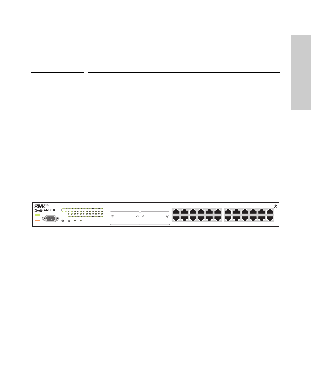
TigerSwitch 10/100 SMC6624M
1
2
3
4
5
6
13
14
15
16
1 2 3 4 5 6 13 14 15 16 17 18
25 26
Console
Power
Fault
789101112192021222324
Self
Reset
Fan
Clear
Test
Status
Link
Act
Link
Act
25
26
8
9
10
11
7
12
20
19
17
21
22
23
10/100 SMC6624M
18
24
1-1
Page 16
Introducing the TigerSwitch 10/100 SMC6624M
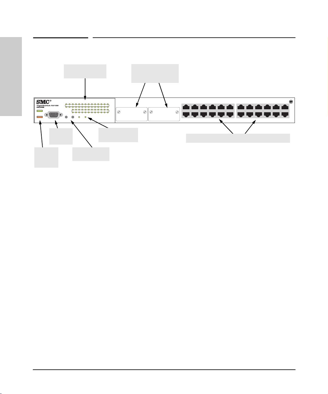
Front of the Switch
Front of the Switch
Introducing the TigerSwitch
10/100 SMC6624M
Console
Power
Fault
Power
and Fault
LEDs
Link and Act LEDs
25 26
Reset
Console
port
for switch ports
1 2 3 4 5 6 13 14 15 16 17 18
789101112192021222324
Self
Fan
Clear
Test
Status
Reset and Clear
buttons
Network Ports
■ 24 autosensing 10/100Base-TX ports.
■ Two module slots for installing any of the supported gigabit and 100 Mbps
Slots for
Gigabit or 100 Mbps
modules
1
2
3
4
5
6
13
14
15
16
17
Link
Act
Link
Act
25
26
8
9
10
11
7
12
20
21
19
18
22
23
24
Self Test and Fan
Status LEDs
10/100Base-TX RJ-45 Auto MDI/MDI-X ports
All these ports support Auto MDI/MDI-X, which means that you can use
either straight-through or crossover twisted-pair cables to connect any
network devices to the switch.
modules.
1-2
Page 17
Introducing the TigerSwitch 10/100 SMC6624M
Front of the Switch
LEDs
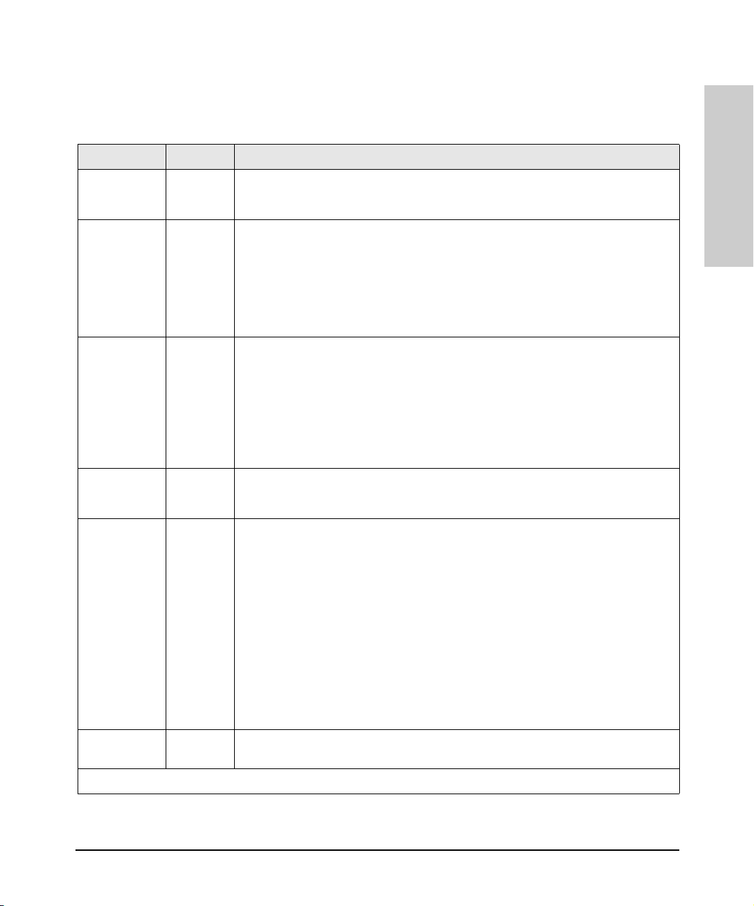
Table 1-1. Switch and Port LEDs
Switch LEDs State Meaning
Power
(green)
Fault
(orange)
Self Test
(green)
Fan Status
(green)
On The switch is receiving power.
Off The switch is NOT receiving power.
Off The normal state; indicates that there are no fault conditions on the switch.
Blinking†A fault has occurred on the switch, one of the switch ports, or the fan. The Status LED
On On briefly after the switch is powered on or reset, at the beginning of switch self test.
Off The normal operational state; the switch is not undergoing self test.
On The switch self test and initialization are in progress after you have power cycled or
Blinking
On The cooling fan is operating normally.
Blinking
for the component with the fault will blink simultaneously.
If this LED is on for a prolonged time, the switch has encountered a fatal hardware
failure, or has failed its self test. See chapter 3, “Troubleshooting” for more information.
reset the switch. The switch is not operational until this LED goes off. The Self Test LED
also comes on briefly when you “hot swap” a module into the switch; the module is self
tested when it is hot swapped.
†
A component of the switch has failed its self test. The status LED for that component,
for example an RJ-45 port, and the switch Fault LED will blink simultaneously.
†
The cooling fan has failed. The switch Fault LED will be blinking simultaneously.
Introducing the TigerSwitch
10/100 SMC6624M
Link On Indicates the port is enabled and receiving a link indication from the connected device.
Off One of these conditions exists:
• no active network cable is connected to the port
• the port is not receiving link beat or sufficient light
• the port has been disabled through the switch console, the web browser interface,
or SNMP management software.
Blinking If the LED is blinking simultaneously with the Fault LED, the corresponding port has
Act (green) On Indicates network activity on the port. Note that the LED will flicker as network traffic
†
The blinking behavior is an on/off cycle once every 1.6 seconds, approximately.
failed its self test.
The LED can blink by itself (no Fault LED blinking) for the module ports. This occurs
when a module is installed and the switch has not yet been reset. Modules can be
installed in the slots while the switch is powered on, but the switch must be reset to
initialize the module and make it operational.
is received and transmitted through the port.
1-3
Page 18

Introducing the TigerSwitch 10/100 SMC6624M
Front of the Switch
Console Port
This port is used to connect a console to the switch by using the serial cable
supplied with the switch. This connection is described under “Connect a
Console to the Switch” in chapter 2, “Installing the Switches”. The console can
be a PC or workstation running a VT-100 terminal emulator, or a VT-100
terminal.
Introducing the TigerSwitch
10/100 SMC6624M
Reset Button
This button is used to reset the switch while it is powered on. This action clears
any temporary error conditions that may have occurred and executes the
switch self test. Press the Reset button also after installing any modules while
the switch is powered on. After installing the module, the switch must be reset
to initialize the module and make it operational.
This button also resets all network activity counters to zero. The counters are
displayed in the SMC6624M console interface, the web browser interface, and
through SNMP network management applications, such as EliteView.
Clear Button
This button is used for these purposes:
■ Deleting Passwords - When pressed by itself for at least one second, the
button deletes any switch console access passwords that you may have
configured. Use this feature if you have misplaced the password and need
console access.
This button is provided for your convenience, but its presence means
that if you are concerned with the security of the switch configuration
and operation, you should make sure the switch is installed in a secure
location, such as a locked wiring closet.
1-4
■ Restoring Factory Default Configuration - When pressed with the
Reset button in a specific pattern, any configuration changes you may
have made through the switch console, the web browser interface, and
SNMP management are removed, and the factory default configuration is
restored to the switch. For the specific method to restore the factory
default configuration, see “Restoring the Factory Default Configuration”
in chapter 3, “Troubleshooting” of this manual.
Page 19
Introducing the TigerSwitch 10/100 SMC6624M
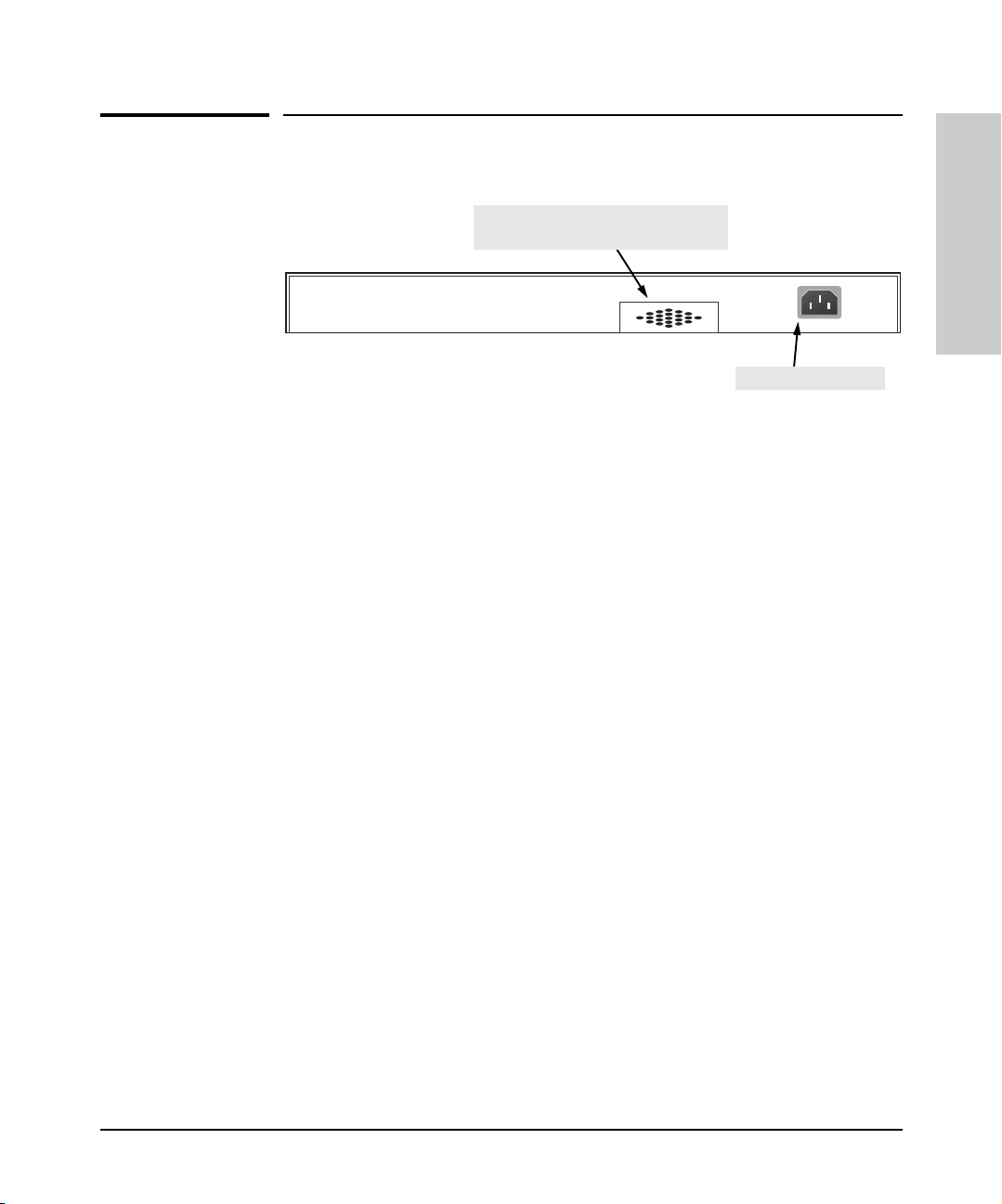
Back of the Switch
Introducing the TigerSwitch
Back of the Switch
.
cooling vent - make sure this is not
obstructed for proper switch operation
Line:50/60Hz
100-127V
~2.4A
200-240V 1.2A
~
AC power connector
Power Connector
The SMC6624M does not have a power switch; it is powered on when
connected to an active AC power source. The switch automatically adjusts to
any voltage between 100-127 and 200-240 volts and either 50 or 60 Hz. There
are no voltage range settings required.
10/100 SMC6624M
1-5
Page 20

Introducing the TigerSwitch
Introducing the TigerSwitch 10/100 SMC6624M
Switch Features
Switch Features
The features of the SMC6624M includes:
■ 24 autosensing 10/100Base-TX RJ-45 ports with Auto MDI/MDI-X.
■ two slots for installing supported gigabit or 100Base-FX modules.
10/100 SMC6624M
■ plug-and-play networking—all ports are enabled—just connect the
■ Auto MDI/MDI-X on all 10/100 twisted-pair ports, and IEEE 802.3ab Auto
■ automatic learning of the network addresses in each switch’s 4096-
■ automatically negotiated full-duplex operation for the fixed 10/100 RJ-45
network cables to active network devices and your switched network is
operational.
MDI /MDI-X on all 100/1000 twisted-pair ports, meaning that all connec-
tions can be made using straight-through twisted-pair cables.
Cross-over cables are not required, although they will also work. The pin
operation of each port is automatically adjusted for the attached device:
if the switch detects that another switch or hub is connected to the port,
it configures the port as MDI; if the switch detects that an end-node device
is connected to the port, it configures the port as MDI-X.
address forwarding table, (with configurable address aging value).
ports when connected to other auto-negotiating devices — the module
ports always operate at full duplex.
1-6
The SMC6624M also includes these network management features:
■ easy management of the switch through several available interfaces:
• web browser interface—an easy to use built-in graphical interface
that can be accessed from common web browsers.
• console interface—a full featured, easy to use, VT-100 terminal
interface that is especially good for out-of-band switch management
or for telnet access to the switch.
• EliteView—an SNMP-based, graphical network management tool
that you can use to manage your entire network.
■ support for the Spanning Tree Protocol to eliminate network loops.
■ support for up to 30 IEEE 802.1Q-compliant VLANs so you can divide the
attached end nodes into logical groupings that fit your business needs.
■ support for many advanced features to enhance network performance
and network traffic control—described in the Management Guide that
came with your SMC6624M.
■ download of new code for product enhancements or bug fixes.
Page 21

Introducing the TigerSwitch 10/100 SMC6624M
Switch Operation Overview
Introducing the TigerSwitch
Switch Operation Overview
Address Table Operation
Address Learning. As devices are connected to the switch ports, either
directly or through hubs or other switches, the MAC addresses of those
devices are learned automatically and stored in the 4096-entry address table
featured by the SMC6624M. The switch also identifies the number of the port
on which each address is learned so they know the network location of each
connected device.
Forwarding, Filtering, Flooding. When the switch receives a packet, it
determines the destination address and looks for the address in the address
table. Based on the port location of that address, the switch then determines
whether to forward, filter-out, or flood the packet.
■ forward - if the destination address is on a different port than the one on
which the packet was received, the packet is forwarded to the destination
port and on to the destination device.
■ filter out - if the destination address is on the same port as the one on
which the packet was received, the packet is filtered out. The switch
thereby isolates local traffic so the rest of the network connected to the
switch does not lose bandwidth dealing with unnecessary traffic.
■ flood - whenever a new destination address is found in a packet received
on a switch port, the destination address will not yet be in the switch’s
address table and the switch cannot know whether to forward or filter out
the packet. In this case, it sends the packet to all the other switch ports.
This is referred to as “flooding”. When the destination device receives the
packet, and it replies, the switch learns the new address from the reply
packet. Then, all future packets destined for that address are forwarded
or filtered out appropriately.
10/100 SMC6624M
Note: Usually, multicast and broadcast packets are flooded, although
configuration of sofware features influence that behavior.
1-7
Page 22

Introducing the TigerSwitch 10/100 SMC6624M
Switch Operation Overview
Network Moves and Changes. When a PC, server, printer, or other
network device is moved in the network, and becomes connected to a different
switch port, the SMC6624M automatically recognizes the change and updates
the address table with the new port location of the device. Communication
with the device is automatically maintained, without any address table manipulation being required by the network administrator.
Introducing the TigerSwitch
10/100 SMC6624M
Effect of VLANs
If you configure multiple virtual LANs (VLANs) on the switch, each VLAN
behaves as a “logical switch” containing the switch ports that you assign to it.
Each logical switch behaves as an isolated broadcast domain, just as if it were
a separate physical switch. The forward, filter, and flood behavior described
for the physical switch above, operates the same for each of the logical
switches defined by the VLANs: packets are forwarded or flooded only to the
ports that are within a given VLAN. Just as for separate isolated physical
switches, there is no communication between ports that are in separate VLANs
unless the VLANs are connected by an external router.
For more information on configuring VLANs and their behavior, see the
Management Guide that came with your switch.
1-8
Page 23

Installing the SMC6624M Switch
The SMC6624M is easy to install. The switch comes with an accessory kit that
includes the brackets for mounting the switch in a standard 19-inch telco rack,
in an equipment cabinet, or on a wall, and with rubber feet that can be attached
so the switch can be securely located on a horizontal surface. The brackets
are designed to allow mounting the switch in a variety of locations and
orientations.
This chapter shows you how to install your SMC6624M switch.
Included Parts
The SMC6624M has the following components shipped with it:
■ TigerSwitch 10/100 SMC6624M Installation Guide (this manual)
■ TigerSwitch 10/100 SMC6624M Management Guide
■ RS-232 Console cable
■ SMC Warranty Registration Card—be sure to complete and return to SMC
■ Accessory kit
• two mounting brackets
• four 8-mm M4 screws to attach the mounting brackets to the switch
• four 5/8-inch number 12-24 screws to attach the switch to a rack
• four rubber feet
■ Power cord—either US, Continental Europe, or UK
2
Installing the SMC6624M
Switch
2-1
Page 24

Switch
Installing the SMC6624M
Installing the SMC6624M Switch
Installation Procedures
Installation Procedures
Summary
Follow these easy steps to install your switch. The rest of this chapter provides
details on these steps.
1. Prepare the installation site (page 2-4). Make sure that the physical
environment into which you will be installing the switch is properly
prepared, including having the correct network cabling ready to connect
to the switch and having an appropriate location for the switch. Please see
page 2-3 for some installation precautions.
2. Install modules (optional—page 2-6). The switches have two slots for
installing any of the supported 1 Gbps (gigabit) or 100 Mbps modules.
Depending on where you will install the switch, it may be easier to install
the modules first.
3. Verify that the switch passes self test (page 2-7). This is a simple
process of plugging the switch into a power source and observing that the
LEDs on the switch’s front panel indicate correct switch operation.
4. Mount the switch (page 2-9). The switch can be mounted in a 19-inch
telco rack, in an equipment cabinet, on a wall, or on a horizontal surface.
The included mounting brackets allow mounting the switch in a variety
of locations and orientations.
5. Connect power to the switch (page 2-13). Once the switch is
mounted, plug it in to the nearby main power source.
6. Connect the network devices (page 2-14). Using the appropriate
network cables, connect the network devices to the switch ports.
7. Connect a console to the switch (optional—page 2-15). You may
wish to modify the switch’s configuration, for example, to configure an IP
address so it can be managed using a web browser, from an SNMP
network management station, or through a Telnet session. Configuration
changes can be made easily by using the included console cable to
connect a PC to the switch’s console port.
At this point, your switch is fully installed. See the rest of this chapter if you
need more detailed information on any of these installation steps.
2-2
Page 25

Installing the SMC6624M Switch
Installation Procedures
Installation Precautions:
Follow these precautions when installing your SMC6624M switch.
Warning ■ The rack or cabinet should be adequately secured to prevent it from
becoming unstable and/or falling over.
Devices installed in a rack or cabinet should be mounted as low as
possible, with the heaviest devices at the bottom and progressively
lighter devices installed above.
Cautions ■ Make sure that the power source circuits are properly grounded, then
use the power cord supplied with the switch to connect it to the power
source.
■ If your installation requires a different power cord than the one supplied
with the switch, be sure to use a power cord displaying the mark of the
safety agency that defines the regulations for power cords in your
country. The mark is your assurance that the power cord can be used
safely with the switch.
Installing the SMC6624M
Switch
■ When installing the switch, note that the AC outlet should be near the
switch and should be easily accessible in case the switch must be
powered off.
■ Ensure that the switch does not overload the power circuits, wiring, and
over-current protection. To determine the possibility of overloading the
supply circuits, add together the ampere ratings of all devices installed
on the same circuit as the switch and compare the total with the rating
limit for the circuit. The maximum ampere ratings are usually printed on
the devices near the AC power connectors.
■ Do not install the switch in an environment where the operating ambient
temperature might exceed 55°C (131°F).
■ Make sure the air flow around the sides and back of the switch is not
restricted.
■ Make sure that if no modules are installed in the module slots, the cover
plates are installed to cover the slots. Cover plates are required for safe
operation, and to ensure proper switch cooling.
2-3
Page 26

Installing the SMC6624M Switch
Installation Procedures
1. Prepare the Installation Site
■ Cabling Infrastructure - Ensure that the cabling infrastructure meets
the necessary network specifications. See the following table for cable
types and lengths, and see appendix B, “Cables and Connectors” for more
information:
Table 2-1. Summary of Cable Types to Use With the Switch
Port Type Cable Type Length Limits
Twisted-Pair Cables
Switch
Installing the SMC6624M
10/100Base-TX • 10 Mbps operation:
Category 3, 4, or 5, 100-ohm unshielded
twisted-pair (UTP)
• 100 Mbps operation:
Category 5, 100-ohm UTP or shielded
twisted-pair (STP) cable.
100/1000Base-T
(on the
SMC6624GT
module)
For either 100 Mbps or 1000 Mbps operation:
Category 5 or better, 100-ohm UTP or shielded
twisted-pair (STP) balanced cable. For 1000
Mbps (gigabit) operation, Category 5E cabling
or better is recommended.
Note: For 1000 Mbps operation, all four wire
pairs are used for data transmission.
100 meters
Note: Since the 10Base-T operation is through
10/100Base-TX ports, if you ever want to upgrade
the ports to 100Base-T, it would be best to cable
the ports initially with category 5 cable.
The 10/100-Base-TX ports on the switch support
Auto MDI/MDI-X, which allows you to use either
straight-through or crossover twisted-pair
cables for connecting to any network devices
including end nodes, such as computers, or to
other switches, hubs, and routers.
100 meters
Note: The 100/1000Base-T module is compatible
with the IEEE 802.3ab standard including the
“Auto MDI/MDI-X” feature, which allows you to
use either straight-through or crossover twis tedpair cables for connecting to any network
devices includ ing end nodes, such as computers,
or to other switches, hubs, and routers.
2-4
Fiber Optic Cables
Page 27

Port Type Cable Type Length Limits
Installing the SMC6624M Switch
Installation Procedures
100Base-FX
(on the
SMC6624FMSC
module)
1000Base-SX
(on the
SMC6624GSSC
module)
1000Base-LX
(on the
SMC6624GLSC
module)
62.5/125 µm or 50/125 µm core/cladding
diameter, graded-index, multimode fiber-optic
cables that are fitted with SC connectors
62.5/125 µm or 50/125 µm core/cladding
diameter, graded-index, multimode fiber-optic
cables that are fitted with SC connectors
Single-mode cables fitted with SC connectors.
62.5/125 µm or 50/125 µm core/cladding
diameter, graded-index, multimode fiber-optic
cables may also be used, but a mode
conditioning patch cord may be needed — see
the Installation Guide that came with the
module for more information.
■ Installation Location - Before installing the switch, plan its location and
• 2 kilometers for full-duplex connections
• 62.5 µm cable:
– 160 MHz*km = 220 meters
– 200 MHz*km = 275 meters
• 50 µm cable:
– 400 MHz*km = 500 meters
– 500 MHz*km = 550 meters
• single-mode cable - 5 kilometers
• multimode cable - 550 meters
orientation relative to other devices and equipment:
• In the front of the switch, leave at least 7.6 cm (3 inches) of space for
the twisted-pair and fiber-optic cabling.
• In the back of the switch, leave at least 3.8 cm (1 1/2 inches) of space
for the power cord.
• On the sides of the switch, leave at least 7.6 cm (3 inches) for cooling,
except if the switch is installed in an open EIA/TIA rack.
Installing the SMC6624M
Switch
2-5
Page 28

Installing the SMC6624M Switch
Installation Procedures
2. Install Modules (optional)
Install a module into one or both of the slots as shown in the illustration below.
For installation details, see the instructions in the Installation Guide that
comes with the module.
The slot cover can be removed with either a flat-bladed or Torx T-10 screwdriver. Keep the slot cover for future use.
Switch
Installing the SMC6624M
Module
Notes
■ Any of the supported Gbps (gigabit) and 100 Mbps modules can be
installed in the slots in the SMC6624M. See “Supported Modules” below.
■ Make sure the modules are fully installed and that you screw in
the retaining screws to secure the modules in place.
■ If you do not install a module in one or both of the slots, make sure that
the slot cover plate(s) is still attached over the slot for safe operation and
proper switch cooling.
■ The modules can be installed while the switch is powered on. Once the
modules are installed, reset the switch by pressing the Reset
button on the front of the switch. This resets/reboots the switch which
initializes and activates the module. Until the switch is reset/rebooted, the
module will not be operational. If you install the modules when the switch
is powered off, powering on the switch after the installation will initialize
the modules.
■ The modules can operate only at full duplex. Half duplex operation is not
supported.
Supported Modules. When this manual was printed, the supported
modules include the following:
■ 1000Base-SX module (SMC6624GSSC)
■ 1000Base-LX module (SMC6624GLSC)
■ 100/1000Base-T module (SMC6624GT)
■ 100Base-FX module (SMC6624FMSC)
■ Stacking module (part of the SMC6624M Gigabit Stacking Kit - S MC6624S)
Note The 1000Base-SX, and 1000Base-LX modules are Class 1 Laser Products
(Laser Klasse 1). They comply with IEC 825-2: 1993.
2-6
Page 29

Installing a Module in the Switch
1. Insert module into the guides and slide it
in until it stops.
2. Press in firmly until the module is flush
with the face of the switch.
3. Tighten the retaining screws on the
module until they secure, but do not
overtighten them.
4. Press th e Reset button to re set/reboot the
switch and initialize the modules.
1 2 3 4 5 6 13 14 15 16 17 18
25 26
789101112192021222324
Self
Reset
Clear
Fan
Test
Status
Installing the SMC6624M Switch
Installation Procedures
Link
Act
Link
Act
25
Rx
Tx
3. Verify the Switch Passes Self Test
Before mounting the switch in its network location, you should first verify that
it is working properly by plugging it into a power source and verifying that it
passes its self test.
1. Connect the power cord supplied with the switch to the power connector
on the back of the switch, and then into a properly grounded electrical
outlet.
Line:50/60Hz
100-127V
~2.4A
200-240V 1.2A
~
Connect power cord to
the power connector
Note The SMC6624M switch does not have a power switch. It is powered on when
the power cord is connected to the switch and to a power source. For safety,
the power outlet should be located near the switch installation.
If your installation requires a different power cord than the one supplied with
the switch, be sure to use a power cord displaying the mark of the safety
agency that defines the regulations for power cords in your country. The mark
is your assurance that the power cord can be used safely with the switch.
Installing the SMC6624M
Switch
2-7
Page 30

Installing the SMC6624M Switch
Installation Procedures
2. Check the LEDs on the switch as described below.
Power
Fault
Console
switch port LEDs
1 2 3 4 5 6 13 14 15 16 17 18
25 26
789101112192021222324
Self
Reset
Clear
Fan
Test
Status
Link
Act
Link
Act
25
26
Switch
Installing the SMC6624M
Power and
Fault LEDs
Self Test LED
When the switch is powered on, it performs its diagnostic self test. Self
test takes approximately 40 seconds to complete.
LED Behavior:
During the self test:
• Initially, all the switch and port LEDs are on and stay on for most of
the duration of the self test.
• Most of the LEDs go off and then may come on again during phases
of the self test. For the duration of the self test, the Self Test LED stays
on.
When the self test completes successfully:
•The Power and Fan Status LEDs remain on.
•The Fault and Self Test LEDs go off.
• The port LEDs on the front of the switch go into their normal opera-
tional mode:
– If the ports are connected to active network devices, the Link
LEDs stay on and the Act LEDs should flicker showing network
activity on the port.
– If the ports are not connected to active network devices, the Link
and Act LEDs will stay off.
2-8
If the LED display is different than what is described above, especially if
the Fault and Self Test LEDs stay on for more than 60 seconds or they start
blinking, the self test has not completed correctly. Refer to chapter 3,
“Troubleshooting” for diagnostic help.
Page 31

Installing the SMC6624M Switch
Installation Procedures
4. Mount the Switch
After you have verified that the switch passes self test, you are ready to mount
the switch in a stable location. The SMC6624M switch can be mounted in these
ways:
■ in a rack or cabinet
■ on a horizontal surface
■ on a wall
Rack or Cabinet Mounting
The SMC6624M switch is designed to be mounted in any EIA-standard 19-inch
telco rack or communication equipment cabinet.
Warning For safe operation, please read the mounting precautions on
page 2-3, before mounting a switch.
1. Use a number 1 Phillips (cross-head) screwdriver and attach the mounting
brackets to the switch with the included 8-mm M4 screws.
Installing the SMC6624M
Switch
8 mm
M4 screws
2-9
Page 32

Switch
Installing the SMC6624M
Installing the SMC6624M Switch
Installation Procedures
Note Steps 2, 3, and 4 below describe a convenient method of mounting the switch
in a rack by placing it on two screws that you first install in the rack. You may,
instead, just hold the switch with attached brackets up to the rack and move
it vertically until rack holes line up with the bracket notches, then insert and
tighten the four screws holding the brackets to the rack.
2. Partially install a screw (5/8-inch number 12-24) into the top hole of a pair
of holes that are 0.5 inches apart in each rack/cabinet upright as shown
in the illustration below. Ensure that the screws are at the same level in
each upright.
.
partially install a screw
into the top hole of a
close (0.5-inch) pair on
both sides of the rack
Note If you are installing the switch in an equipment cabinet, in place of the 12-24
screws supplied with the switch, use the clips and screws that came with the
cabinet. Plan which four holes you will be using in the cabinet and install all
four clips and partially install the two bottom screws (as shown in the
illlustration above) before proceeding to step 3.
2-10
Page 33

.
lower switch with moun ting
brackets onto the partially
installed screw
Installing the SMC6624M Switch
Installation Procedures
3. Place the switch in the rack and lower it so the notches in the bottom of
the bracket slide onto the screws, then tighten these screws.
Installing the SMC6624M
Switch
4. Install the other number 12-24 screw through the hole in each bracket.
Tighten these screws.
install additiona l
screw
2-11
Page 34

Switch
Installing the SMC6624M
Installing the SMC6624M Switch
Installation Procedures
Horizontal Surface Mounting
Place the switch on a table or other horizontal surface. The switch comes with
rubber feet in the accessory kit that can be used to help keep the switch from
sliding on the surface. Attach the rubber feet to the four corners on the bottom
of the switch within the embossed angled lines. Use a sturdy surface in an
uncluttered area. You may want to secure the networking cables and switch
power cord to the table leg or other part of the surface structure to help
prevent tripping over the cords.
Caution Make sure the air flow is not restricted around the sides and back of the switch.
Wall Mounting
You can mount the switch on a wall as shown in the illustrations on the next
page.
Caution The switch should be mounted only to a wall or wood surface that is at least
1/2-inch plywood or its equivalent.
1. Use a #1 Phillips (cross-head) screwdriver and attach the mounting
brackets to the switch with the included 8-mm M4 screws.
2-12
For “Bookshelf” Wall Mounting For “Flat” Wall Mounting
M4 screws
M4 screws
Page 35

Installing the SMC6624M Switch
2. Attach the switch to the wall or wood surface with two 5/8-inch number
12 wood screws (not included).
For “Bookshelf” Wall Mounting For “Flat” Wall Mounting
5/8-inch
wood screw
5/8-inch
wood screws
Installation Procedures
Installing the SMC6624M
Switch
second 5/8-inch
wood screw (hidden)
5. Connect the Switch to a Power Source
1. Plug the included power cord into the switch’s power connector and into
a nearby AC power source.
2. Re-check the LEDs during self test. See “LED Behavior” on page 2-8.
2-13
Page 36

Switch
Installing the SMC6624M
Installing the SMC6624M Switch
Installation Procedures
6. Connect the Network Cables
Connect the network cables, described under “Cabling Infrastructure” (page
2-4), from the network devices or your patch panels to the fixed RJ-45 ports
on the switch or the ports on any modules you have installed in the switch.
Using the RJ-45 Connectors (10/100Base-TX ports)
To c o nn e ct :
Push the RJ-45 plug into the RJ-45
jack until the tab on the plug clicks
into place. When power is on for the
switch and for the connected device,
the Link LED for the port should light
to confirm a powered-on device (for
example, an end node) is at the other
end of the cable.
If the Link LED does not go on when
the network cable is connected to the
port, see “Diagnosing With the LEDs”
in chapter 3, “Troubleshooting”.
To disconnect:
Press the small tab on the plug and
pull the plug out of the jack
1
28394
7
Unshielded twisted-pair cable:
• Category 3, 4, or 5 for 10 Mbps ports
• Category 5 only for 100 Mbps ports
Maximum distance: 100 meters
10
RJ-45 connector
.
2-14
Connecting Cables to the Modules
If you have any modules installed in the switch, the type of network connections you will need to use depends on the type of modules you have installed.
See the documentation accompanying the modules for cabling configurations
and procedures for those modules.
The module documentation will also cover troubleshooting procedures for
connections to the modules, but, in general for all the switch ports, when a
network cable from an active network device is connected to the port, the
Link LED for that port should go on. If the Link LED does not go on when the
network cable is connected to the port, see “Diagnosing With the LEDs” in
chapter 3, “Troubleshooting”.
Page 37

Installing the SMC6624M Switch
Installation Procedures
7. (Optional) Connect a Console to the Switch
The SMC6624M switch has a full-featured, easy to use console interface for
performing the following tasks:
■ Monitor switch and port status and observe network activity statistics
■ Modify the switch’s configuration to optimize switch performance,
enhance network traffic control, and improve network security
■ Read the event log and access diagnostic tools to help in troubleshooting
■ Download new software to the switch
■ Add passwords to control access to the switch from the console, web
browser interface, and network management stations
The console can be accessed through these methods:
■ Out-of-band: The SMC6624M switch comes with a serial cable for con-
necting a PC or VT-100 terminal, to be used as a console, directly to the
switch.
■ In-Band: Access the console using Telnet from a PC or UNIX station on
the network, and a VT-100 terminal emulator. This method requires that
you first configure the switch with an IP address and subnet mask by using
either out-of-band console access or through DHCP/Bootp. See the
section “Getting Started With Switch Configuration” later in this chapter,
and the Management Guide that came with your switch for more information on IP addressing and on starting a Telnet session.
Installing the SMC6624M
Switch
The SMC6624M switch can simultaneously support one out-of-band console
session through the Console Port and one in-band Telnet console session.
Terminal Configuration
To connect a console to the switch, configure the PC terminal emulator as a
DEC VT-100 (ANSI) terminal or use a VT-100 terminal, and configure either
one to operate with these settings:
• any baud rate from 1200 to 115200 (the switch senses the speed)
• 8 data bits, 1 stop bit, no parity, and flow control set to None
• For the Windows Terminal program, also disable (uncheck) the “Use
Function, Arrow, and C
• For the Hilgrave HyperTerminal program, select the “Terminal keys”
option for the “Function, arrow, and ctrl keys act as” parameter.
If you want to operate the console using a different configuration, make sure
you change the settings on both the terminal and on the switch so they are
compatible. Change the switch settings first, then change the terminal
settings, then reboot the switch and reestablish the console session.
trl Keys for Windows” option
2-15
Page 38

Installing the SMC6624M Switch
s
Installation Procedures
Connecting a Console
Switch
Installing the SMC6624M
To connect a console to the
switch, follow these steps:
1. Connect the PC or
console port
Power
Fault
12345
25 26
Console
7891011
Self
Reset
Clear
Test
terminal to the switch’s
Console Port using the
console cable included
with the switch. (If your
PC or terminal has a 25-pin
serial connector, first
attach a 9-pin to 25-pin
console cable s upplied
with the switch
straight-through adapter
at one end of the console
cable.)
2. Turn on the terminal or
PC’s power and, if using a
PC running a terminal
emulator program, or
a VT-100 terminal
PC, start the PC terminal
program.
3. Press Enter two or three times and you will see the copyright page and
the message “Press any key to continue”. Press a key, and you will then
see the switch console command (CLI) prompt, for example:
SMC TigerSwitch 10/100#
Fan
Statu
2-16
If you want to continue with console management of the switch at this time,
see the next section, “Getting Started With Switch Configuration” for some
simple configuration steps, and refer to the Management Guide that came
with your switch for more detailed configuration information.
Page 39

Getting Started With Switch Configuration
Installing the SMC6624M Switch
Getting Started With Switch
Configuration
This section is a guide for using the console Switch Setup screen to quickly
assign an IP (Internet Protocol) address and subnet mask to the switch, set a
Manager password, and, optionally, configure other basic features.
For more information on using the switch console and the other switch
management interfaces: the web browser interface and the SNMP management tool, EliteView, please see the Management Guide that came with your
switch.
Installing the SMC6624M
Recommended Minimal Configuration
In the factory default configuration, the switch has no IP (Internet Protocol)
address and subnet mask, and no passwords. In this state, it can be managed
only through a direct console connection. To manage the switch through inband (networked) access, you should configure the switch with an IP address
and subnet mask compatible with your network. Also, you should configure
a Manager password to control access privileges from the console and web
browser interface. Other parameters in the Switch Setup screen can be left at
their default settings or you can configure them with values you enter.
Many other features can be configured through the switch’s console interface,
to optimize the switch’s performance, to enhance your control of the network
traffic, and to improve network security. Once an IP address has been configured on the switch, these features can be accessed more conveniently through
a remote Telnet session, through the switch’s web browser interface, and from
an SNMP network management station running a network management
program, such as EliteView. For a listing of switch features available with and
without an IP address, refer to “How IP Addressing Affects Switch Operation”
in the Management Guide that came with your SMC6624M switch.
For more information on IP addressing, refer to “IP Configuration” in the
Management Guide.
Note By default, the switch is configured to acquire an IP address configuration
from a DHCP or Bootp server. To use DHCP/Bootp instead of the manual
method described in this chapter, see “DHCP/Bootp Operation” in the
Management Guide that came with your switch.
Switch
2-17
Page 40

Switch
Installing the SMC6624M
Installing the SMC6624M Switch
Getting Started With Switch Configuration
Using the Console Setup Screen
The quickest and easiest way to minimally configure the switch for management and password protection in your network is to use a direct console
connection to the switch, start a console session, and access the Switch Setup
screen.
1. Using the method described in the preceding section, connect a terminal
device to the switch and display the switch console command (CLI)
prompt (the default display).
The CLI prompt appears displaying the switch model number:
SMC TigerSwitch 10/100#
2. At the prompt, enter the setup command to display the Switch Setup
screen. The following illustration shows the Setup screen with the default
settings.
2-18
3. Use the Tab key to select the Manager Password field and enter a manager
password of up to 16 characters.
4. Tab to the IP Config (DHCP/Bootp) field and use the Space bar to select the
Manual option.
5. Tab to the IP Address field and enter the IP address that is compatible with
your network.
6. Tab to the Subnet Mask field and enter the subnet mask used for your
network.
7. Press Enter, then “S” (for S
ave).
Page 41

Getting Started With Switch Configuration
Installing the SMC6624M Switch
Here is some information on the fields in the Setup screen. For more information on these fields, see the Management Guide that came with your switch:
Parameter Default
System Name blank Optional; up to 25 characters, including spaces
System Contact blank Optional; up to 48 characters, including spaces
Manager Password blank Recommended; up to 16 characters (no blank spaces)
Logon Default CLI The default setting selects the command line interface for console access.
The alternative is the menu interface.
Time Zone 0 (none) Optional; 1440 to -1440. The number of minutes your location is to the West
(+) or East (-) of GMT.
Community Name public Default setting recommended.
Spanning Tree Enabled No Default setting recommended unless STP is already running on your network
or the switch will be used in complex network topologies.
Default Gateway blank Optional; Enter the IP address of the next-hop gateway node if network traffic
needs to be able to reach off-subnet destinations.
TimeP Config DHCP Optional; The method the switch uses to acquire the TimeP server address.
IP Config (DHCP/Bootp) DHCP/Bootp Set to Manual unless a DHCP/Bootp server is used on your network to
configure IP addressing.
IP Address xxx.xxx.xxx.xxx Recommended; If you set IP Config to Manual, then enter an IP address
compatible with your network.
Note: The IP address and subnet mask assigned for the switch must be compatible with the IP addressing used in
your network. For more information on IP addressing, see the Management Guide that came with your switch.
Subnet Mask xxx.xxx.xxx.xxx Recommended; If you entered an IP address, then enter a subnet mask
compatible with your network.
The switch is now configured with a Manager password, IP address, and
subnet mask, and can be accessed through your network using Telnet, the web
browser interface, or an SNMP-based network management tool such as
EliteView.
Installing the SMC6624M
Switch
To Recover from a Lost Manager Password: If you cannot start a console session at the manager level because of a lost Manager password, you
can clear all passwords and user names by getting physical access to the
switch and pressing and holding the Clear button for a full second.
2-19
Page 42

Installing the SMC6624M Switch
Using the IP Address for Remote Switch Management
Where to Go From Here
The above procedure configures your switch with a Manager password, IP
address, and subnet mask. With the proper network connections, you can
now manage the switch from a PC equipped with Telnet and/or a web browser
or from an SNMP network management station.
Some basic information on managing your switch is included in the next
section. For more information on the console, web browser, and SNMP
management interfaces and all the features that can be configured on the
SMC6624M switch, please see the Management Guide that came with your
switch.
Using the IP Address for Remote Switch
Switch
Installing the SMC6624M
Management
With your SMC6624M switch, you can use the switch’s IP address to manage
the switch from any PC that is on the same subnet as the switch. You can use
either a Telnet session or a standard web browser to manage the switch.
Starting a Telnet Session
To access the switch through a Telnet session, follow these steps:
1. Make sure the switch is configured with an IP address and that the switch
is reachable from the PC that is running the Telnet session (for example,
by using a Ping command to the switch’s IP address).
2. Start the Telnet program on a PC that is on the same subnet as the switch
and connect to the switch’s IP address.
3. You will see the copyright page and the message “Press any key to
continue”. Press a key, and you will then see the switch console command
(CLI) prompt, for example:
SMC TigerSwitch 10/100#
Enter help or ? to see a list of commands that can be executed at the
prompt. Entering any command followed by help provides more detailed
context help information about the command.
2-20
Page 43

Using the IP Address for Remote Switch Management
Installing the SMC6624M Switch
Starting a Web Browser Session
Your SMC6624M switch can be managed through a graphical interface that
you can access from any PC or workstation on the network by running your
web browser and typing in the switch’s IP address as the URL. No additional
software installation is required to make this interface available; it is included
in the switch’s onboard software.
A typical web browser interface screen is shown in the next illustration.
Installing the SMC6624M
Switch
For more information on using the web browser interface, please see the
Management Guide that came with your switch.
2-21
Page 44

Installing the SMC6624M Switch
Sample Network Topologies
Sample Network Topologies
This section shows you a few sample network topologies in which the
SMC6624M switch is implemented.
As a Desktop Switch
Server
Switch
Installing the SMC6624M
twisted-pair
“straight-through”
or “crossover”
cables
The SMC6624M switch is designed to be used primarily as a desktop switch
to which end nodes, printers and other peripherals, and servers are directly
connected, as shown in the above illustration. Notice that the end node
devices are connected to the switch by “straight-through” or “crossover”
twisted-pair cables. Either cable type can be used because of the “Auto MDI/
MDI-X” feature on the switch.
SMC6624M
18
17
16
15
14
13
6
5
4
24
3
23
2
22
1
21
20
19
12
6
2
11
10
9
5
8
2
7
8
1
7
k
1
n
i
L
6
1
5
1
4
1
t
3
c
A
61
5
k
n
i
L
1234
t
6
c
2
A
5
2
4
2
3
2
2
2
1
2
0
2
9
1
2
1
11
0
91
e
l
o
s
n
78
o
C
n
a
F
f
s
l
u
e
t
S
Sta
t
s
r
a
Te
e
l
C
r
e
t
w
e
o
s
P
e
R
t
l
u
a
F
PCs and
peripherals
2-22
Page 45

As a Segment Switch
Installing the SMC6624M Switch
Sample Network Topologies
Server with
“Gigabit”
Ethernet NIC
Gigabit
fiber-optic cable
to backbone
“Fast”
Ethernet
Hubs
twisted-pair
“straight-through”
cables to
end nodes
category 5 twisted-pair “straight-through” or
“crossover” cable for 1000 Mbps connection to server
twisted-pair “straight-
through” or “crossover”
cables to hubs
PCs,
r
e
w
o
P
t
l
u
a
F
6
2
5
2
e
l
o
s
n
o
C
t
e
s
e
R
Printers
SMC6624M
18
17
16
15
14
13
6
5
4
24
3
23
2
22
1
21
20
19
12
6
2
1
1
10
9
5
8
2
7
8
1
7
k
1
n
i
L
6
1
5
1
4
1
t
3
c
A
561
k
n
i
L
34
12
t
c
A
4
2
3
2
2
2
1
2
0
2
9
1
2
111
0
1
789
n
a
F
f
s
l
u
e
t
S
Sta
t
s
r
a
Te
e
l
C
Printers
printers,
and local
servers
The SMC6624M switch also works well as a segment switch. That is, with its
high performance, it can be used for interconnecting network segments —
simply connect the network hubs that form those segments to the switch, or
you can also connect other switches.
In the illustration above, two “Fast” Ethernet hubs with PCs, printers, and local
servers attached, are both connected to a SMC6624M. The devices attached
to the two hubs can now communicate with each other through the switch.
They can also all communicate with the server that is connected to the switch
through a 100/1000Base-T module installed in the switch.
Installing the SMC6624M
Switch
Because the SMC6624M switch has the “Auto MDI/MDI-X” feature, the connections between the switch and the hubs, and between the switch and end nodes
or servers can be through category 5 “straight-through” or “crossover” twistedpair cable. Category 3 or 4 cable can also be used if the connection is 10 Mbps
only. In all cases, the device ports must be configured to auto negotiate the
link characteristics for this feature to work.
The switch, in turn, can be connected to a network backbone through fiberoptic cabling connected to a 1000Base-SX/LX module installed in the switch.
Now, all the devices on these network segments can access other network
resources that are connected elsewhere on the network backbone.
2-23
Page 46

Installing the SMC6624M Switch
Sample Network Topologies
Connecting to a Backbone Switch
to Gigabit-Ethernet
backbone
A
A
Link
EFGHIJ
1X
A
Link
D
Mode
1X
A
2X
Link
C
Mode
1X
A
2X
Mode
Link
Mode
A
AB
Tx
1
Rx
Reset
Link
Clear
Tx
Mode
Power
Console
2
Fault
Rx
Switch Engine Fail
Self Test
Tx
Act
Tx
Fdx
Mode
Rx
3
Select
100
Rx
Status
A
Tx
B
C
4
D
E
Rx
F
Modules
G
H
I
J
1
2
Power
Fan
3X
2X
3X
Link
4X
3X
Mode
Link
4X
Mode
5X
4X
5X
Tx
6X
5X
Tx
6X
Rx
7X
6X
Rx
7X
8X
7X
8X
8X
SMC6624M
18
17
16
15
14
13
6
5
4
24
3
23
2
22
1
21
20
19
12
6
2
11
10
9
5
8
2
7
8
1
7
k
1
n
i
L
6
1
5
1
4
1
t
3
c
Gigabit
fiber-optic cable
A
A
A
Link
1X
Mode
2X
3X
4X
5X
6X
7X
8X
A
61
5
k
n
i
L
234
1
t
6
c
2
A
5
2
4
2
3
2
2
2
1
2
0
2
9
1
2
111
0
1
e
l
o
s
n
789
o
C
n
a
F
f
s
l
u
e
t
S
Sta
t
s
r
a
Te
e
l
C
r
e
t
w
e
o
s
P
e
R
t
l
u
a
F
Switch
Installing the SMC6624M
Backbone Switch
5
4
3
2
1
6
2
11
10
9
5
8
2
7
8
1
7
k
1
n
i
L
6
1
5
1
4
1
t
3
c
A
61
k
n
i
L
12345
t
6
c
2
A
5
2
4
2
3
2
2
2
1
2
0
2
9
1
2
111
0
891
e
l
o
s
n
7
o
C
n
a
F
f
s
l
u
e
t
S
Sta
t
s
r
a
Te
e
l
C
r
e
t
w
e
o
s
P
e
R
t
l
u
a
F
15
14
13
6
21
20
19
12
SMC6624M
18
17
16
24
23
22
Printers
Printers
The simpler desktop and segment networks shown in the previous two
examples can easily be combined and expanded. For example, you could use
a backbone switch to interconnect each of your smaller switched workgroups
to form a larger switched network. All the devices in this network can
communicate with each other. With a 1000Base-SX module, for example, in
the backbone switch, the entire switched topology could be connected to a
campus backbone, as shown in the illustration above.
Note In the illustration above, the 1000 Mbps fiber-optic connection between the
SMC6624M and the backbone switch is by way of a 1000Base-SX module
installed in the switch.
2-24
Page 47

Installing the SMC6624M Switch
Sample Network Topologies
Stacking the Switches
SMC6624M switches can be connected together, through standard network
connections, and managed through a single IP address. Up to 16 switches can
be connected together in such a “virtual stack”.
You identify one of the switches as the “Commander” and give that switch an
IP address. Up to 15 other switches in the network can then easily be
configured as Members of the stack and managed through the Commander’s
IP address. The management includes Telnet access and web browser interface access to the Commander and to each Member switch through the
Commander.
For more information on stacking SMC6624M switches, please see the
Management Guide that came with your switch.
Installing the SMC6624M
Switch
2-25
Page 48

Page 49

Troubleshooting
This chapter describes how to troubleshoot your SMC6624M switch. Note that
this document describe s troubleshooting mostly from a hardwa re perspective.
You can perform more in-depth troubleshooting on the SMC6624M switch
using the software tools available with the switch, including the full-featured
console interface, the built-in web browser interface, and EliteView, the
SNMP-based network management tool. See the Troubleshooting chapter of
the Management Guide included with the switch for more information.
This chapter describes the following:
■ basic troubleshooting tips (page 3-1)
■ diagnosing with the LEDs (page 3-4)
■ proactive networking tools (page 3-8)
■ hardware diagnostic tests (page 3-9)
■ restoring the factory default configuration (page 3-11)
■ downloading new code (page 3-12)
■ SMC Technical Support Services (page 3-13)
3
Troubleshooting
Basic Troubleshooting Tips
Most problems are caused by the following situations. Check for these items
first when starting your troubleshooting:
■ Faulty or loose cables. Look for loose or obviously faulty connections.
If they appear to be OK, make sure the connections are snug. If that does
not correct the problem, try a different cable.
■ Non-standard cables. Non-standard and miswired cables may cause
network collisions and other network problems, and can seriously impair
network performance. Use a new correctly-wired cable or compare your
cable to the cable in appendix B, “Cables and Connectors” for pinouts and
correct cable wiring. A category 5 cable tester is a recommended tool for
every 100Base-TX and 1000Base-T network installation.
3-1
Page 50

Troubleshooting
Basic Troubleshooting Tips
■ Improper Network Topologies. It is important to make sure you have
a valid network topology. Common topology faults include excessive
cable length and excessive repeater delays between end nodes. If you have
network problems after recent changes to the network, change back to
the previous topology. If you no longer experience the problems, the new
topology is probably at fault. Sample topologies are shown at the end of
chapter 2 in this book.
In addition, you should make sure that your network topology contains
no data path loops. Between any two end nodes, there should be only
one active cabling path at any time. Data path loops will cause broadcast
storms that will severely impact your network performance.
If you wish to build redundant paths between important nodes in your
network to provide some fault tolerance, you should enable Spanning
Tree Protocol support on the switch. This ensures that only one of the
redundant paths is active at any time, thus avoiding data path loops.
Spanning Tree can be enabled through the switch console, the web
browser interface, or EliteView.
The switch also supports Trunking, which allows multiple network
cables to be used for a single network connection without causing a data
path loop. See the Management Guide that came with the switch for more
information on Spanning Tree and on Trunking.
■ Connecting to devices that have a fixed full-duplex configuration.
The SMC6624M switch RJ-45 ports are configured as “Auto.” That is, when
connecting to attached devices, the switch will operate in one of two ways
to determine the link speed and the communication mode (half duplex or
full duplex):
• if the connected device is also configured to Auto, the switch will
automatically negotiate both link speed and communication mode
Troubleshooting
• if the connected device has a fixed configuration, for example 100
Mbps, at half or full duplex, the switch will automatically sense the
link speed, but will default to a communication of half duplex
3-2
Because the SMC6624M switch behaves in this way (in compliance with
the IEEE 802.3 standard), if a device connected to the switch has a fixed
configuration at full duplex, the device will not connect correctly to the
switch. The result will be high error rates and very inefficient communications between the switch and the device.
Make sure that all devices connected to the SMC6624M switch are configured to auto negotiate, or are configured to connect at half duplex (all
hubs are configured this way, for example).
Page 51

Basic Troubleshooting Tips
■ Check the port configuration. A port on your switch may not be
Troubleshooting
operating as you expect because it has been put into a “blocking” state by
Spanning Tree, GVRP (automatic VLANs), or LACP (automatic trunking).
(Note that the normal operation of the Spanning Tree, GVRP, and LACP
features may put the port in a blocking state.) Or, the port just may have
been configured as disabled through software.
Use the switch console to determine the port’s configuration and verify
that there is not an improper or undesired configuration of any of the
switch features that may be affecting the port. See the Management Guide
that came with your switch for more information.
3-3
Troubleshooting
Page 52

Troubleshooting
Diagnosing with the LEDs
Diagnosing with the LEDs
Tables 3-1 shows LED patterns on the switch and the switch modules that
indicate problem conditions.
1. Check in the table for the LED pattern that you see on your switch.
2. Refer to the corresponding diagnostic tip on the next few pages.
Table 3-1. LED Error Indicators
LED Pattern Indicating Problems
Fan
Power Fault Self Test
Off with
power cord
plugged in
On Prolonged On Prolonged On * *
On Blinking
On Blinking
On Blinking
On Off Off * Off with cable
On Off Off * On, but the port is
Troubleshooting
On Off Off * Blinking
* This LED is not important for the diagnosis.
†
The blinking behavior is an on/off cycle once every 1.6 seconds, approximately.
****
†
Blinking
†
†
Off Blinking
Blinking
Status
†
†
**
* Blinking
Port Link
†
not communicating
*
connected
†
†
Diagnostic
Tips
3-4
Page 53

Diagnostic Tips:
Tip Problem Solution
Diagnosing with the LEDs
Troubleshooting
The switch is not
plugged into an
active AC power
source, or the
switch’s power
supply may have
failed.
A switch
hardware failure
has occurred. All
the LEDs will stay
on indefinitely.
The switch has
experienced a
software failure
during self test.
The switch
cooling fan may
have failed.
The port
associated with
the blinking Link
LED has failed
self test.
1. Verify that the power cord is plugged into an active power source and to the switch.
Make sure these connections are snug.
2. Try power cycling the switch by unplugging and plugging the power cord back in.
3. If the Power LED is still not on, verify that the AC power source works by plugging
another device into the outlet. Or try plugging the switch into a different outlet or try a
different power cord.
If the power source and power cord are OK and this condition persists, the switch power
supply may have failed. Contact SMC Technical Support for assistance.
Try power cycling the switch. If the fault indication reoccurs, the switch may have failed.
Contact SMC Technical Support for assistance.
1. Try resetting the switch by pressing the Reset button on the front of the switch, or by
power cycling the switch.
2. If the fault indication reoccurs, attach a console to the switch (as indicated in chapter
2) and configure it to operate at 9600 baud. Then, reset the switch. Messages should
appear on the console screen and in the console log identifying the error condition.
You can view the console log at that point by selecting it from the console Main Menu.
If necessary to resolve the problem, Contact SMC Technical Support for assistance.
Try disconnecting power from the switch and wait a few moments. Then reconnect the
power to the switch and check the LEDs again. If the error indication reoccurs, the fan
has failed and the switch should be replaced as soon as possible. Contact SMC Technical
Support for assistance.
Try power cycling the switch. If the fault indication reoccurs, the switch port may have
failed. Contact SMC Technical Support for assistance.
Troubleshooting
continued on the next page
3-5
Page 54

Troubleshooting
Diagnosing with the LEDs
Tip Problem Solution
The network
connection is not
working
properly.
Try the following procedures:
• For the indicated port, verify that both ends of the cabling, at the switch and the
connected device, are connected properly.
• Verify the connected device and switch are both powered on and operating correctly.
• Verify that you have used the correct cable type for the connection:
– For twisted-pair connections to the fixed 10/100 ports or to the port on a
100/1000Base-T module, if the port is configured to “Auto” (auto negotiate), either
“straight-t hrough” or “crossover” cables can be used bec ause of the switch’s Auto
MDI/MDI-X feature.
If, however, the switch port is configured with a fixed configuration, for example
100 Mbps/full-duplex, the switch port then operates as MDI-X only, and you must
use the correct cable type for the connection. In general, in this case, for
connecting an en d node to the switch, use “strai ght- through” cable; for conne cting
MDI-X ports on hubs or other switches, use “crossover” cable.
– For fiber-optic connections, verify that the transmit p ort on the switch is connected
to the receive port on the connected device, and the switch receive port is
connected to the transmit port on the connected device.
• For 1000Base-T connections, verify that the network cabling complies with the IEEE
802.3ab standard. The cable should be installed according to the ANSI/TIA/EIA-568A-5 specifications. Cable testing should comply with the stated limitations for Attenuation, Near-End Crosstalk, Far-End Crosstalk, Equal-Level Far-End Crosstalk, and Return Loss.
The cable verification process must include all patch cables from any end devices,
including the switch, to any patch panels in the cabling path.
• Verify that the port has not been disabled through a switch configuration change.
You can use the console interface, or, if you have configured an IP address on the
switch, use the web browser interface, or EliteView network management software
to determine the state of the port and re-enable the port if necessary.
• If the other procedures don’t resolve t he problem, try using a different port or a different
cable.
The port may be
Troubleshooting
improperly
configured, or
the port may be in
a “blocking”
state by the
normal operat ion
of the Spanning
Tree, L A C P, o r
IGMP features.
Use the switch console to see if the port is part of a dynamic trunk (through the LACP
feature) or to see if Spanning Tree is enabled on the switch, and to see if the port may
have been put into a “blocking” state by those features. The show lacp command displays
the port status for the LACP feature; the show spanning-tree command displays the port
status for Spanning Tree.
Also check the Port Status screen using the show interfaces command to see if the port
has been configured as “disabled”.
Other switch features that may affect the port operation include VLANs and IGMP. Use
the switch console to see how the port is configured for these features.
For software troubleshooting tips, see chapter 8, “Troubleshooting” in the Management
Guide that came with your switch.
Make sure also, that the device at the other end of the connection is indicating a good
link to the switch. If it is not, the problem may be with the cabling between the devices or
the connectors on the cable.
3-6
Page 55

Tip Problem Solution
Diagnosing with the LEDs
Troubleshooting
A module was
installed and the
switch has not
yet been reset.
When you install modules in the module slots, you must reset or reboot the switch so the
switch processor can properly initialize and configure the module. The flashing LED
informs you that the module is not initialized. The module will not work properly until the
switch is reset or rebooted.
Troubleshooting
3-7
Page 56

Troubleshooting
Proactive Networking
Proactive Networking
The SMC6624M switch has built-in management capabilities that proactively
help you manage your network, including:
■ finding and helping you fix the most common network error conditions
(for example, faulty network cabling, and non-standard network topologies)
■ informing you of the problem with clear, easy-to-understand messages
■ recommending network configuration changes to enhance the perfor-
mance of your network
The following interfaces provide tests, indicators, and an event log that can
be used to monitor the switch and its network connections and to help you
take advantage of these proactive networking features:
■ EliteView - an SNMP-based network management tool.
■ A graphical web browser interface that you can use to manage your switch
from a PC running a supported web browser, for example Microsoft
Internet Explorer, and Netscape Communicator.
■ A full-featured easy-to-use console interface that you can access by
connecting a standard terminal or PC running a terminal emulator to the
switch’s console port. The cable to make that connection is provided with
your switch. The console interface is also accessible through a telnet
connection.
See the “Troubleshooting” chapter in the Management Guide that came with
your switch for more information on using these software tools to diagnose
and manage your switch.
Troubleshooting
3-8
Page 57

Hardware Diagnostic Tests
Troubleshooting
Hardware Diagnostic Tests
Testing the Switch by Resetting It
If you believe that the switch is not operating correctly, you can reset the
switch to test its circuitry and operating code. To reset a switch, either:
■ Unplug and plug in the power cord (power cycling)
■ Press the reset button on the front of the switch
Power cycling the switch and pressing the Reset button both cause the switch
to perform its power-on selftest, which almost always will resolve any temporary operational problems. These reset processes also cause any network
traffic counters to be reset to zero, and cause the System Up Time timer to
reset to zero.
Checking the Switch LEDs
The self test passes if the Fault and Self Test LEDs on the front of the switch
go off after approximately 40 seconds. If these LEDs stay on longer than 60
seconds or begin blinking, there may be a problem with the switch.
See “Diagnosing With the LEDs” on page 3-4 for information on interpreting
the LED patterns.
Checking Console Messages
Useful diagnostic messages may be displayed on the console screen when the
switch is reset. As described in chapter 2 under step 7, “Connect a Console to
the Switch”, connect a PC running a VT-100 terminal emulator program or a
standard VT-100 terminal to the switch’s Console Port and configure it to run
at 9600 baud, and with the other terminal communication settings shown on
page 2-15. Then, when you reset the switch, note the messages that are
displayed. Additionally, you can check the switch event log, which can be
accessed from the console using the show log command, or from the console
Main Menu.
3-9
Troubleshooting
Page 58

Troubleshooting
Hardware Diagnostic Tests
Testing Twisted-Pair Cabling
Network cables that fail to provide a link or provide an unreliable link between
the switch and the connected network device may not be compatible with the
IEEE 802.3 Type 10Base-T, 100Base-TX, or 1000Base-T standards. The
twisted-pair cables attached to the SMC6624M switch must be compatible
with the appropriate standards. To verify that your cable is compatible with
these standards, use a qualified cable test device.
Testing Switch-to-Device Network Communications
You can perform the following communication tests to verify that the network
is operating correctly between the switch and any connected device that can
respond correctly to the communication test.
■ Link Test -- a physical layer test that sends IEEE 802.2 test packets to any
device identified by its MAC address
■ Ping Test -- a network layer test used on IP networks that sends test
packets to any device identified by its IP address
These tests can be performed through the switch console interface from a
terminal connected to the switch or through a telnet connection, or from the
switch’s web browser interface. See the Management Guide that came with
your switch for more information.
These tests can also be performed from an SNMP network management
station running a program that can manage the switch, for example, EliteView.
Testing End-to-End Network Communications
Troubleshooting
3-10
Both the switch and the cabling can be tested by running an end-to-end
communications test -- a test that sends known data from one network device
to another through the switch. For example, if you have two PCs on the
network that have LAN adapters between which you can run a link-level test
or Ping test through the switch, you can use this test to verify that the entire
communication path between the two PCs is functioning correctly. See your
LAN adapter documentation for more information on running a link test or
Ping test.
Page 59

Restoring the Factory Default Configuration
Troubleshooting
Restoring the Factory Default
Configuration
As part of your troubleshooting process on the SMC6624M switch, it may
become necessary to return the switch configuration to the factory default
settings. This process momentarily interrupts the switch operation, clears any
passwords, clears the console event log, resets the network counters to zero,
performs a complete self test, and reboots the switch into its factory default
configuration including deleting the IP address, if one is configured.
Note This process removes all switch configuration changes that you have made
from the factory default settings. This includes, for example, configuration of
VLANs, spanning tree, trunks, and stacking. Returning the configuration of
these features to their factory default settings (usually disabling them) may
result in network connectivity issues.
If the switch has a valid configuration, and you are restoring the factory default
settings for a reason other than configuration problems, you should save the
switch configuration prior to performing the factory default reset. Then, after
the reset and resolution of the original problem, you can restore the saved
configuration to the switch. For both the save and restore processes, you can
use the console copy command. See the switch Management Guide for more
information on this command.
Troubleshooting
You can restore the factory default configuration either on the switch itself,
or through the switch console.
To execute the factory default reset on the switch, perform these steps:
1. Using pointed objects, simultaneously press both the Reset and Clear
buttons on the front of the switch.
2. Continue to press the Clear button while releasing the Reset button.
3. When the Self Test LED begins to blink, release the Clear button.
The switch will then complete its self test and begin operating with its
configuration restored to the factory default settings.
To restore the factory default configuration using the console, execute the
delete startup config command from the console command prompt.
3-11
Page 60

Troubleshooting
Downloading New Code
Downloading New Code
New code can be downloaded to the SMC6624M switch through several
methods, for product enhancements and new features. Please see the Manage-
ment Guide that came with your switch for more information. The new code
would be available on the SMC web site, http://www.smc.com.
Troubleshooting
3-12
Page 61

SMC Technical Support Services
Troubleshooting
SMC Technical Support Services
If you are still having trouble with your switch, SMC offers support 24 hours
a day, seven days a week through the use of a number services. See the back
cover of this manual for information on how to use these services to get
technical support.
Before Calling Support
Before calling your networking dealer or SMC Technical Support, to make the
support process most efficient, you first should have retrieved the following
information:
Information Item Information Location
• product identification the front of the switch: TigerSwitch 10/100 SMC6624M
• switch’s OS (software)
version
• copy of the switch configuration
• copy of the switch Event
Log
• copy of the switch status
and counters information,
including the detailed
counters for the problem
port(s)
• copy of your network
topology map, including
network addresses assigned to the relevant devices
switch console: show version command (Firmware
revision field)
switch console: show configuration command
switch console: show log command
switch console: show statistics command, and
show statistics <port list> command
your network records
Troubleshooting
3-13
Page 62

Page 63

Specifications
Physical
Width: 44.2 cm (17.4 in)
Depth: 20.5 cm (8.1 in)
Height: 4.4 cm (1.7 in)
Weight: 2.8 kg (6.2 lbs)
A
Electrical
The switches automatically adjust to any voltage between 100-127 and
200-240 volts and either 50 or 60 Hz.
AC voltage: 100–127 volts 200–240 volts
Maximum current: 2.4 A 1.2 A
Frequency range: 50/60 Hz 50/60 Hz
Environmental
Operating Non-Operating
Temperature: 0°C to 55°C (32°F to 131°F) -40°C to 70°C (-40°F to 158°F)
Relative humidity:
(non-condensing)
Maximum altitude: 4.6 Km (15,000 ft) 4.6 Km (15,000 ft)
15% to 95% at 40°C (104°F) 15% to 90% at 65°C (149°F)
Specifications
A-1
Page 64

Specifications
Acoustic
Geraeuschemission LwA=54 dB am fiktiven Arbeitsplatz nach DIN 45635 T.19
Noise Emission LwA=54 dB at virtual workspace according to DIN 45635 T.19
Connectors
■ The 10/100 Mbps RJ-45 twisted-pair ports are compatible with the
IEEE 802.3u 100Base-TX and IEEE 802.3 Type 10Base-T standards.
■ The 1000 Mbps RJ-45 twisted-pair port on the 100/1000Base-T module is
compatible with the IEEE 802.3ab standard.
■ The 100 Mbps SC fiber-optic port on the 100Base-FX module is compatible
with the IEEE 802.3u 100Base-FX standard.
■ The 1000 Mbps SC fiber-optic ports on the 1000Base-SX and 1000Base-LX
modules are compatible with the IEEE 802.3z 1000Base-SX and
1000Base-LX standards.
Safety
Complies with:
■ EN60950 / IEC 950
■ CSA 22.2 No. 950
■ NOM-019-SCFI-1994
■ UL 1950
Specifications
A-2
Page 65

Switch Ports and Network Cables
This appendix includes switch connector information and network cable
information for cables that should be used with the SMC6624M switch,
including minimum pin-out information and specifications for twisted-pair
cables.
Note Incorrectly wired cabling is the most common cause of problems for LAN
communications. SMC recommends that you work with a qualified LAN cable
installer for assistance with your cabling requirements.
Switch Ports
Twisted Pair
■ The fixed RJ-45 10/100Base-TX ports on the switches and the RJ-45
connector on the 100/1000Base-T module accept 100-ohm unshielded and
shielded twisted-pair cable with RJ-45 connectors as described on the
next page.
B
Switch Ports and Network
Cables
Fiber-Optic
■ The SC-type connector port on the 100Base-FX module transmits at 1300
nm wavelength, and accepts the multimode fiber-optic cables for 100BaseFX described on the next page.
■ The SC-type connector port on the 1000Base-SX module transmits at 850
nm wavelength, and accepts the multimode fiber-optic cables for
1000Base-SX described on the next page.
■ The SC-type connector port on the 1000Base-LX module transmits at 1300
nm wavelength, and accepts the single mode or multimode fiber-optic
cables for 1000Base-LX described on the next page.
B-1
Page 66

Switch Ports and Network Cables
Cables
Twisted-Pair
Cables
10 Mbps Operation Category 3, 4, or 5 100-ohm unshielded twisted-pair (UTP)
or shielded twisted-pair (STP) cable, complying with IEEE
802.3 Type 10Base-T specifications, fitted with RJ-45
connectors
Switch Ports and Network
100 Mbps Operation Category 5 100-ohm UTP or STP cable, complying with
IEEE 802.3u 100Base-TX specifications, fitted with RJ-45
connectors
1000 Mbps Operation Category 5 100-ohm 4-pair UTP or STP cable, complying
with IEEE 802.3ab 1000Base-T specifications, fitted with
RJ-45 connectors—Category 5E or better is recommended
(please see “Note on 1000Base-T Cable Requirements”,
below)
Note on 1000Base-T Cable Requirements. The Category 5 networking
cables that work for 100Base-TX connections should also work for
1000Base-T, as long as all four-pairs are connected. But, for the most robust
connections you should use cabling that complies with the Category 5E
specifications, as described in Addendum 5 to the TIA-568-A standard (ANSI/
TIA/EIA-568-A-5).
Because of the increased speed provided by 1000Base-T, network cable quality
is more important than for either 10Base-T or 100Base-TX. Cabling plants
being used to carry 1000Base-T networking must comply with the IEEE
802.3ab standards. In particular, the cabling must pass tests for Attenuation,
Near-End Crosstalk (NEXT), and Far-End Crosstalk (FEXT). Additionally,
unlike the cables for 100Base-TX, the 1000Base-T cables must pass tests for
Equal-Level Far-End Crosstalk (ELFEXT) and Return Loss.
B-2
When testing your cabling, be sure to include the patch cables that connect
the switch and other end devices to the patch panels on your site. The patch
cables are frequently overlooked when testing cable and they must also
comply with the cabling standards.
Page 67

Switch Ports and Network Cables
Twisted-Pair Cable/Connector Pin-Outs
Fiber-Optic
100Base-FX 62.5/125 µm or 50/125 µm (core/cladding) diameter, graded-
index, multimode fiber-optic cables, complying with the
ITU-T G.651 and ISO/IEC 793-2 Type A1b or A1a respectively, fitted with MT-RJ connectors
1000Base-SX 62.5/125 µm or 50/125 µm (core/cladding) diameter, graded-
index, multimode fiber-optic cables, complying with the
ITU-T G.651 and ISO/IEC 793-2 Type A1b or A1a respectively, fitted with SC or MT-RJ connectors, depending on
the module used
1000Base-LX single mode fiber-optic cables, complying with the ITU-T
G.652 and ISO/IEC 793-2 Type B1 standards, fitted with SC
or MT-RJ connectors
OR
62.5/125 µm or 50/125 µm (core/cladding) diameter, gradedindex, multimode fiber-optic cables, complying with the
ITU-T G.651 and ISO/IEC 793-2 Type A1b or A1a respectively, fitted with SC or MT-RJ connectors
Note: Multimode fiber-optic cabling may be used for a
1000Base-LX application, but a mode conditioning patch
cord may be needed. See the Installation Guide that came
with your module for more information.
Switch Ports and Network
Cables
Twisted-Pair Cable/Connector Pin-Outs
The Auto MDI/MDI-X Feature: In the default configuration, “Auto”, the
fixed 10/100Base-TX ports on the SMC6624M switch all automatically detect
the type of port on the connected device and operate as either an MDI or MDIX port, whichever is appropriate. So for any connection, a “straight-through”
twisted-pair cable can be used -- you no longer have to use “crossover” cables,
although “crossover” cables can also be used for any of the connections. (The
100/1000Base-T module supports the IEEE 802.3ab standard, which includes
the Auto MDI/MDI-X feature.)
If you connect a SMC6624M switch twisted-pair port to another switch or hub,
which typically have MDI-X ports, the SMC6624M switch port automatically
operates as an MDI port. If you connect it to an end node, such as a server or
PC, which typically have MDI ports, the SMC6624M switch port operates as
an MDI-X port. In all cases, you can use standard “straight through” cables or
“crossover” cables.
B-3
Page 68

Switch Ports and Network Cables
Twisted-Pair Cable/Connector Pin-Outs
Cables
If you happen to use a correctly wired crossover cable, though, the switch will
still be able to automatically detect the MDI/MDI-X operation and link
correctly to the connected device.
If the port configuration is changed to any of the fixed configurations though,
for example 100 Mbps/full duplex, the port operates as MDI-X only and the
correct cable type must be used: for connections to MDI ports, such as end
nodes, use a “straight-through” cable; for connections to MDI-X ports, such as
on hubs and other switches, use a “crossover” cable.
Switch Ports and Network
Other Wiring Rules:
■ All twisted-pair wires used for 10 Mbps, and 100 Mbps operation must be
twisted through the entire length of the cable. The wiring sequence must
conform to EIA/TIA 568-B (not USOC). See “Twisted-Pair Cable Pin
Assignments” later in this appendix for a listing of the signals used on each
pin.
■ For 1000Base-T connections, all four pairs of wires in the cable must be
available for data transmission. Please see “Note on 1000Base-T Cable
Requirements” on page B-2 for more information on 1000Base-T
cabling.
■ For 10 Mbps connections to the ports, you can use Category 3, 4, or 5
unshielded twisted-pair cable, as supported by the IEEE 802.3 Type
10Base-T standard.
■ For 100 Mbps connections to the ports, use 100-ohm Category 5 UTP or
STP cable only, as supported by the IEEE 802.3u Type 100Base-TX standard.
■ For 1000 Mbps connections, 100-ohm Category 5E or better cabling is
recommended.
B-4
Page 69

Switch Ports and Network Cables
Twisted-Pair Cable/Connector Pin-Outs
Straight-Through Twisted-Pair Cable for 10 Mbps or 100 Mbps Network Connections
Because of the Auto MDI/MDI-X operation of the 10/100 ports on the switch,
for all network connections, to PCs, servers or other end nodes, or to hubs or
other switches, you can use “straight-through” cables.
If any of these ports are given a fixed configuration, for example 100 Mbps/
Full Duplex, the ports operate as MDI-X ports, and straight-through cables
must be then used for connections to PC NICs and other MDI ports.
Cable Diagram
Switch Ports and Network
Cables
Note Pins 1 and 2 on connector “A” must be wired as a twisted pair to pins 1 and 2
on connector “B”.
Pins 3 and 6 on connector “A” must be wired as a twisted pair to pins 3 and 6
on connector “B”.
Pins 4, 5, 7, and 8 are not used in this application, although they may be wired
in the cable.
.
Pin Assignments
Switch End (MDI-X) Computer, Module, or Other
Signal Pins Pins Signal
receive +
receive transmit +
transmit -
1
2
3
6
End
1
2
3
6
transmit +
transmit receive +
receive -
B-5
Page 70

Switch Ports and Network Cables
Twisted-Pair Cable/Connector Pin-Outs
Crossover Twisted-Pair Cable for 10 Mbps or 100 Mbps Network Connection
The Auto MDI/MDI-X operation of the 10/100 ports on the switch also allows
you to use “crossover” cables for all network connections, to PCs, servers or
other end nodes, or to hubs or other switches.
Cables
Switch Ports and Network
If any of these ports are given a fixed configuration, for example 100 Mbps/
Full Duplex, the ports operate as MDI-X ports, and crossover cables must be
then used for connections to hubs or switches or other MDI-X network
devices.
Cable Diagram
Note Pins 1 and 2 on connector “A” must be wired as a twisted pair to pins 3 and 6
on connector “B”.
Pins 3 and 6 on connector “A” must be wired as a twisted pair to pins 1 and 2
on connector “B”.
Pins 4, 5, 7, and 8 are not used in this application, although they may be wired
in the cable.
.
Pin Assignments
B-6
Switch End (MDI-X) Hub or Switch Port, or Other
Signal Pins Pins Signal
receive +
receive transmit +
transmit -
1
2
3
6
MDI-X Port End
6
3
2
1
transmit transmit +
receive receive +
Page 71

Switch Ports and Network Cables
Twisted-Pair Cable/Connector Pin-Outs
Straight-Through Twisted-Pair Cable for 1000 Mbps Network Connections
1000Base-T connections require that all four pairs or wires be connected.
Cable Diagram
Switch Ports and Network
Cables
Note Pins 1 and 2 on connector “A” must be wired as a twisted pair to pins 1 and 2
on connector “B”.
Pins 3 and 6 on connector “A” must be wired as a twisted pair to pins 3 and 6
on connector “B”.
Pins 4 and 5 on connector “A” must be wired as a twisted pair to pins 4 and 5
on connector “B”.
Pins 7 and 8 on connector “A” must be wired as a twisted pair to pins 7 and 8
on connector “B”.
.
Pin Assignments
For 1000Base-T operation, all four pairs of wires are used for both transmit
and receive.
B-7
Page 72

Page 73

Index
Numerics
10/100Base-TX ports
location on switch … 1-2
100/1000Base-T
connections, length limitations … 2-4
ports, cables used with … 2-4
1000Base-LX
connections, length limitations … 2-5
ports, cables used with … 2-5, B-3
1000Base-SX
connections, length limitations … 2-5
ports, cables used with … 2-5, B-3
100Base-FX
connections, length limitations … 2-5
ports, cables used with … 2-5, B-3
100Base-TX
connections, length limitations … 2-4
ports, cables used with … 2-4
10Base-T
connections, length limitations … 2-4
ports, cables used with … 2-4
A
AC power connector
location on back of switch … 1-5
Act indicator LED … 1-3
address learning … 1-7
address table
automatic address learning … 1-7
filtering out traffic … 1-7
flooding traffic … 1-7
forwarding traffic … 1-7
moves and changes … 1-8
operation … 1-7
Auto MDI/MDI-X operation … B-3, B-5, B-7
Auto MDI/MDI-X, feature description … B-3
B
back of switch
description … 1-5
power connector … 1-5
backbone switch
topology with … 2-24–2-25
basic switch configuration
IP address … 2-18
manager password … 2-18
subnet mask … 2-18
Switch Setup screen … 2-18
basic troubleshooting tips … 3-1
blinking LEDs
error indications … 3-4
Bootp
automatic switch configuration … 2-17
for in-band access … 2-15
buttons
Clear button … 1-4
Reset button … 1-4
C
cabinet
mounting the switch in … 2-9
cables
100/1000Base-T connections … 2-4
1000Base-LX
connections … 2-5
fiber-optic cable specifications … B-3
1000Base-SX
connections … 2-5
fiber-optic cable specifications … B-3
100Base-FX
connections … 2-5
fiber-optic cable specifications … B-3
100Base-TX connections … 2-4
10Base-T connections … 2-4
connecting cables to switch ports … 2-14
effects of non-standard cables … 3-1
fiber-optic, specifications … B-3
infrastructure requirements … 2-4
length limitations … 2-4
required types … 2-4
serial, for direct console connection … 2-16
cables, twisted pair
category 3, 4, 5 … B-4
cross-over cable pin-out … B-6
MDI-X to MDI connections … B-5, B-7
Index
Index – 1
Page 74

MDI-X to MDI-X connections … B-6
pin-outs … B-5, B-7
straight-through cable pin-out … B-5, B-7
switch-to-computer connection … B-5, B-7
switch-to-switch or hub connection … B-6
cables, twisted-pair
Auto MDI/MDI-X feature … B-3
specifications … B-2
wiring rules … B-4
cables, twisted-pair connector pin-outs … B-3
cabling infrastructure … 2-4
Clear button
deleting passwords … 1-4
description … 1-4
location on switch … 1-2, 1-4
restoring factory default configuration … 1-4,
3-11
to delete password protection … 2-19
CLI prompt, console
displaying … 2-16
configuration
checking when troubleshooting … 3-3
DHCP/Bootp … 2-17
full duplex only for modules … 2-6
IP address … 2-18
IP address, manually … 2-18
manager password … 2-18
restoring factory defaults … 1-4, 3-11
subnet mask … 2-18
Switch Setup screen … 2-18
connecting the switch to a power source … 2-13
Index
connector specifications … A-2
console
checking messages during
troubleshooting … 3-9
displaying the CLI prompt … 2-16
features … 2-15
how to connect in-band … 2-15
how to connect out-of-band … 2-15
serial cable connection … 2-16
Switch Setup screen … 2-18
telnet access … 2-20
terminal configuration … 2-15
console port
description … 1-4
location on switch … 1-2, 1-4
cross-over cable
pin-out … B-6
D
deleting passwords … 1-4
description
back of switch … 1-5
front of switch … 1-2
LEDs … 1-3
switch … 1-1
desktop switch
sample topology … 2-22
DHCP
automatic switch configuration … 2-17
for in-band access … 2-15
diagnostic tests … 3-9
checking the console messages … 3-9
checking the LEDs … 3-9
end-to-end connectivity … 3-10
testing the switch only … 3-9
testing twisted-pair cabling … 3-10
downloading new code … 3-12
E
electrical specifications, switch … A-1
environmental specifications, switch … A-1
F
factory default configuration, restoring … 1-4, 3-11
Fan Status LED … 1-3
Fault LED … 1-3
behavior during self test … 2-8
behaviors … 1-3
blinking definition … 1-3
location on switch … 1-2
showing error conditions … 3-4
features
console … 2-15
switch … 1-6
fiber-optic cables … B-3
1000Base-LX … B-3
1000Base-SX … B-3
100Base-FX … B-3
filtering out traffic … 1-7
flooding traffic … 1-7
forwarding traffic … 1-7
front of switch
10/100Base-TX ports … 1-2
Clear button … 1-4
2 – Index
Page 75

console port … 1-4
description … 1-2
LEDs … 1-3
network ports … 1-2
Reset button … 1-4
slot for switch modules … 1-2
full-duplex fixed configuration
effects on network connections … 3-2
full-duplex operation of modules … 2-6
H
horizontal surface
mounting switch on … 2-12
I
in-band … 2-17
in-band console access
types of … 2-15
included parts … 2-1
installation
connecting the switch to a power source … 2-13
horizontal surface mounting … 2-12
location considerations … 2-5
network cable requirements … 2-4
optional modules … 2-6
precautions … 2-3
rack or cabinet mounting … 2-9
site preparation … 2-4
summary of steps … 2-2
wall mounting … 2-12
IP address
configuring … 2-18
using for switch management … 2-20
L
LEDs
Act … 1-3
behavior during self test … 2-8
blinking definition … 1-3
checking during troubleshooting … 3-9
descriptions of … 1-3
display for uninitialized module … 1-3
error indications … 3-4
Fan Status … 1-3
Fault … 1-3
behavior during self test … 2-8
showing error conditions … 3-4
Link … 1-3
location on switch … 1-2
on switch … 1-3
Power … 1-3
behavior during self test … 2-8
Self Test … 1-3
behavior during self test … 2-8
length limitations
100/1000Base-T connections … 2-4
1000Base-LX connections … 2-5
1000Base-SX connections … 2-5
100Base-FX connections … 2-5
100Base-TX connections … 2-4
10Base-T connections … 2-4
Link LEDs … 1-3
display for uninitialized module … 1-3
link test … 3-10
location for the switch, considerations … 2-5
M
MDI-X to MDI network cable … B-5, B-7
MDI-X to MDI-X network cable … B-6
modules
full-duplex operation … 2-6
initializing by switch reset … 2-6
installing … 2-6
LED indication when uninitialized … 1-3
slot, location on switch … 1-2
supported types … 2-6
mounting the switch
in a rack or cabinet … 2-9
precautions … 2-3
on a horizontal surface … 2-12
on a wall … 2-12
precautions … 2-12
moves and changes
effect on address table … 1-8
N
network cables
100/1000Base-T connections … 2-4
1000Base-LX connections … 2-5
1000Base-SX connections … 2-5
100Base-FX connections … 2-5
Index
Index – 3
Page 76

100Base-TX connections … 2-4
10Base-T connections … 2-4
Auto MDI/MDI-X feature … B-3
fiber-optic, specifications … B-3
required types … 2-4
twisted-pair connector pin-outs … B-3
twisted-pair, specifications … B-2
twisted-pair, wiring rules … B-4
network devices
connecting to the switch … 2-14
network ports
connecting to … 2-14
location on switch … 1-2
standards compliance … A-2
types of … 1-2, 2-4
non-standard network cables, effects … 3-1
O
out-of-band console access … 2-20
P
parts, included with the switch … 2-1
password
configuring … 2-18
deleting with the Clear button … 2-19
if you lose the password … 2-19
passwords, deleting … 1-4
physical specifications, switch … A-1
Ping test … 3-10
Index
pin-outs
twisted-pair cables … B-3
port configuration
checking when troubleshooting … 3-3
port LEDs
Link … 1-3
normal operation … 2-8
ports
10/100Base-TX, location on switch … 1-2
Auto MDI/MDI-X feature … B-3
connecting to … 2-14
console … 1-4, 2-15
network connections … 2-14
power connector … 1-5
Power LED … 1-3
behavior during self test … 2-8
behaviors … 1-3
location on switch … 1-2
power source
connecting the switch to … 2-13
precautions
mounting the switch … 2-3
power requirements … 2-3
preparing the installation site … 2-4
proactive network tools
diagnostics with … 3-8
R
rack
mounting precautions … 2-3
mounting the switch in … 2-9
Reset button
description … 1-4
location on switch … 1-2, 1-4
restoring factory default configuration … 3-11
resetting the switch
factory default reset … 3-11
initializing modules … 2-6
location of Reset button … 1-4
troubleshooting procedure … 3-9
S
safety specifications … A-2
segment switch
sample topology … 2-23
self test
Fault LED behavior … 2-8
LED behavior during … 2-8
Power LED behavior … 2-8
Self Test LED … 1-3
behavior during factory default reset … 3-11
behavior during self test … 2-8
serial cable
for direct console connection … 2-16
slots for modules
location on switch … 1-2
specifications
connectors … A-2
electrical … A-1
environmental … A-1
physical … A-1
safety … A-2
straight-through cable
4 – Index
Page 77

pin-out … B-5, B-7
subnet mask
configuring … 2-18
summary
of cables used with the switch … 2-4
of switch installation … 2-2
supported modules … 2-6
switch
connecting to a power source … 2-13
description … 1-1
electrical specifications … A-1
environmental specifications … A-1
features … 1-6
front panel description … 1-2
included parts … 2-1
LED descriptions … 1-3
mounting in a rack or cabinet … 2-9
mounting on a wall … 2-12
mounting on horizontal surface … 2-12
operation … 1-7
physical specifications … A-1
switch modules
installing … 2-6
switch operation
address table … 1-7
description … 1-7
effect of VLANs … 1-8
filtering out traffic … 1-7
flooding traffic … 1-7
forwarding traffic … 1-7
network moves and changes … 1-8
verifying after installation … 2-7
Switch Setup screen … 2-18
configuring a subnet mask … 2-18
configuring an IP address … 2-18
field descriptions … 2-19
switch operation … 3-9
switch-to-device communications … 3-10
twisted-pair cabling … 3-10
tips for troubleshooting … 3-1
topologies
effects of improper topology … 3-2
samples of … 2-22
troubleshooting … 3-1
basic tips … 3-1
checking port configuration … 3-3
checking the console messages … 3-9
checking the LEDs … 3-9
common network problems … 3-1
connecting to fixed full-duplex devices … 3-2
diagnostic tests … 3-9
effects of improper topology … 3-2
effects of non-standard cables … 3-1
link test … 3-10
Ping test … 3-10
proactive network tools … 3-8
restoring factory default configuration … 3-11
testing connections to other devices … 3-10
testing end-to-end communications … 3-10
testing the switch … 3-9
testing the twisted-pair cables … 3-10
twisted-pair cable
cross-over cable pin-out … B-6
pin-outs … B-3, B-5, B-7
straight-through cable pin-out … B-5, B-7
switch-to-computer connection … B-5, B-7
switch-to-switch or hub connection … B-6
testing … 3-10
twisted-pair cables … B-2
twisted-pair ports
Auto MDI/MDI-X feature … B-3
Index
T
telnet access to the console … 2-20
terminal configuration … 2-15
testing
checking the console messages … 3-9
checking the LEDs … 3-9
diagnostic tests … 3-9
end-to-end communications … 3-10
link test … 3-10
Ping test … 3-10
V
VLANs, effect on basic switch operation … 1-8
VT-100 terminal
serial cable connection for … 2-16
W
wall
mounting switch on … 2-12
warranty … 1-i
wiring rules for twisted-pair cables … B-4
Index – 5
Page 78

Page 79

Page 80

FOR TECHNICAL SUPPORT, CALL:
From U.S.A. and Canada (24 hours, 7 days a week)
(800) SMC-4-YOU; (949) 707-2400; (949) 707-2460 (Fax)
From Europe (8:00 AM - 5:30 PM UK Greenwich Mean Time)
44 (0) 1188 748740; 44 (0) 1189 748741 (Fax)
INTERNET
E-mail addresses:
techsupport@smc.com
european.techsupport@smc-europe.com
Driver updates:
http://www.smc.com/support.html
World Wide Web:
http://www.smc.com/
FTP Site:
ftp.smc.com
FOR LITERATURE OR ADVERTISING RESPONSE, CALL:
U.S.A. and Canada: (800) SMC-4-YOU; Fax (949) 707-2460
Spain: 34-93-477-4920; Fax 34-93-477-3774
UK: 44 (0) 1188 748700; Fax 44 (0) 1189 748701
Southern Europe: 33 (1) 41.18.68.68; Fax 33 (1) 41.18.68.69
Central/Eastern Europe: 49 (0) 89 92861-200; Fax 49 (0) 89 92861-230
Nordic: 46 (8) 564 33145; Fax 46 (8) 87 62 62
Middle East: 971-48818410; Fax 971-48817993
South Africa: 27 (0) 11-3936491; Fax 27 (0) 11-3936491
PRC: 86-10-6235-4958; Fax 86-10-6235-4962
Taiwan: 886-2-2659-9669; Fax 886-2-2659-9666
Asia Pacific: (65) 238 6556; Fax (65) 238 6466
Korea: 82-2-553-0860; Fax 82-2-553-7202
Japan: 81-45-224-2332; Fax 81-45-224-2331
Australia: 61-2-9416-0437; Fax 61-2-9416-0474
India: 91-22-8204437; Fax 91-22-8204443
6 Hughes
Irvine, CA 92618
Phone: (949) 707-2400
Model Numbers: SMC6624M
Publication Number: 150000001400A
Revision Number: F2.05 E082001-R01
 Loading...