

Page 1
TigerStack II 10/100
12- and 24-Port 10/100 Mbps Hubs
u
Forms a stack with up to 144 ports
u
Manageable via SNMP and RMON
u
10/100BASE-TX and 100BASE-FX extension modules
u
Support for redundant power unit
User Guide
SMC5912DS
SMC5924DS
SMC5912
SMC5924
Page 2

TigerStack II 10/100
User Guide
From SMC’s Tiger line of feature-rich workgroup LAN solutions
6 Hughes
Irvine, CA 92618
Phone: (949) 707-2400
May 1999
Pub. # 150914-101 R02
Page 3

Information furnished by SMC Networks, Inc. (SMC) is believed to
be accurate and reliable. However, no responsibility is assumed by
SMC for its use, nor for any infringements of patents or other rights
of third parties which may result from its use. No license is granted
by implication or otherwise under any patent or patent rights of
SMC. SMC reserves the right to change specifications at any time
without notice.
Copyright © 1999 by
SMC Networks, Inc.
6 Hughes
Irvine, CA 92618
All rights reserved. Printed in Taiwan
Trademarks:
SMC is a registered trademark; and EZ Switch, TigerStack and TigerSwitch are trademarks of
SMC Networks, Inc. Other product and company names are trademarks or registered trademarks of their respective holders.
Page 4

Limited Warranty
HARDWARE: SMC Networks, Inc. (“SMC”) warrants its TigerStack II 10/100
Hubs to be free from defects in workmanship and materials, under normal
use and service, for the following lengths of time from the date of purchase
from SMC or its Authorized Reseller:
TigerStack II 10/100 Hubs . . . . . . . . . . . . . . . . . . . . . . . . . . . . Three Years
If a product does not operate as warranted during the applicable warranty
period, SMC shall, at its option and expense, repair the defective product or
part, deliver to Customer an equivalent product or part to replace the
defective item, or refund to Customer the purchase price paid for the
defective product. All products that are replaced will become the property
of SMC. Replacement products may be new or reconditioned. Any replaced
or repaired product or part has a ninety (90) day warranty or the remainder
of the initial warranty period, whichever is longer.
SMC shall not be responsible for any custom software or firmware,
configuration information, or memory data of Customer contained in, stored
on, or integrated with any products returned to SMC pursuant to any
warranty.
SOFTWARE: SMC warrants that the software programs licensed from it will
perform in substantial conformance to the program specifications for a period
of ninety (90) days from the date of purchase from SMC or its Authorized
Reseller. SMC warrants the magnetic media containing software against
failure during the warranty period. No updates are provided. SMC’s sole
obligation hereunder shall be (at SMC’s discretion) to refund the purchase
price paid by Customer for any defective software products or to replace
any defective media with software which substantially conforms to SMC’s
applicable published specifications. Customer assumes responsibility for the
selection of the appropriate applications program and associated reference
materials. SMC makes no warranty that its software products will work in
combination with any hardware or applications software products provided
by third parties, that the operation of the software products will be
uninterrupted or error free, or that all defects in the software products will
be corrected. For any third party products listed in the SMC software
product documentation or specifications as being compatible, SMC will make
reasonable efforts to prove compatibility, except where the noncompatibility is caused by a “bug” or defect in the third party’s product.
STANDARD WARRANTY SERVICE: Standard warranty service for hardware
products may be obtained by delivering the defective product, accompanied
by a copy of the dated proof of purchase, to SMC’s Service Center or to an
Authorized SMC Service Center during the applicable warranty period.
Standard warranty service for software products may be obtained by
telephoning SMC’s Service Center or an Authorized SMC Service Center,
within the warranty period. Products returned to SMC’s Service Center must
be pre-authorized by SMC with a Return Material Authorization (RMA)
number marked on the outside of the package, and sent prepaid, insured,
Page 5

L
IMITED WARRANTY
and packaged appropriately for safe shipment. The repaired or replaced
item will be shipped to Customer, at SMC’s expense, not later than thirty
(30) days after receipt by SMC.
WARRANTIES EXCLUSIVE: IF AN SMC PRODUCT DOES NOT OPERATE
AS WARRANTED ABOVE, CUSTOMER’S SOLE REMEDY SHALL BE REPAIR,
REPLACEMENT OR REFUND OF THE PURCHASE PRICE PAID, AT SMC’S
OPTION. THE FOREGOING WARRANTIES AND REMEDIES ARE
EXCLUSIVE AND ARE IN LIEU OF ALL OTHER WARRANTIES OR
CONDITIONS, EXPRESS OR IMPLIED, EITHER IN FACT OR BY OPERATION
OF LAW, STATUTORY OR OTHERWISE, INCLUDING WARRANTIES OR
CONDITIONS OF MERCHANTABILITY AND FITNESS FOR A PARTICULAR
PURPOSE. SMC NEITHER ASSUMES NOR AUTHORIZES ANY OTHER
PERSON TO ASSUME FOR IT ANY OTHER LIABILITY IN CONNECTION
WITH THE SALE, INSTALLATION, MAINTENANCE OR USE OF ITS
PRODUCTS.
SMC SHALL NOT BE LIABLE UNDER THIS WARRANTY IF ITS TESTING
AND EXAMINATION DISCLOSE THE ALLEGED DEFECT IN THE PRODUCT
DOES NOT EXIST OR WAS CAUSED BY CUSTOMER’S OR ANY THIRD
PERSON’S MISUSE, NEGLECT, IMPROPER INSTALLATION OR TESTING,
UNAUTHORIZED ATTEMPTS TO REPAIR, OR ANY OTHER CAUSE BEYOND
THE RANGE OF THE INTENDED USE, OR BY ACCIDENT, FIRE,
LIGHTNING, OR OTHER HAZARD.
LIMITATION OF LIABILITY: IN NO EVENT, WHETHER BASED IN
CONTRACT OR TORT (INCLUDING NEGLIGENCE) SHALL SMC BE LIABLE
FOR INCIDENTAL, CONSEQUENTIAL, INDIRECT, SPECIAL, OR PUNITIVE
DAMAGES OF ANY KIND, OR FOR LOSS OF REVENUE, LOSS OF BUSINESS,
OR OTHER FINANCIAL LOSS ARISING OUT OF OR IN CONNECTION
WITH THE SALE, INSTALLATION, MAINTENANCE, USE, PERFORMANCE,
FAILURE, OR INTERRUPTION OF ITS PRODUCTS, EVEN IF SMC OR ITS
AUTHORIZED RESELLER HAS BEEN ADVISED OF THE POSSIBILITY OF
SUCH DAMAGES NOTHING HEREIN SHALL HAVE THE EFFECT OF
LIMITING OR EXCLUDING SMC’S LIABILITY FOR DEATH OR PERSONAL
INJURY CAUSED BY NEGLIGENCE.
Some states do not allow the exclusion of implied warranties or the
limitation of incidental or consequential damages for consumer products, so
the above limitations and exclusions may not apply to you. This warranty
gives you specific legal rights which may vary from state to state. Nothing
in this warranty shall be taken to affect your statutory rights.
SMC Networks, Inc.
6 Hughes
Irvine, CA 92618
Page 6

TABLE OF CONTENTS
Compliances ............................................................... v
1 About the Hubs ................................................ 1-1
Overview ................................................................................. 1-2
How to Use this Guide ............................................................ 1-5
Twisted-Pair Ports .................................................................... 1-5
Status LEDs .............................................................................. 1-6
Switch Module ......................................................................... 1-7
Optional Network Management Module ................................. 1-8
Optional Extender Modules ..................................................... 1-9
Stacking Connectors .............................................................. 1-12
Optional Redundant Power Unit ........................................... 1-13
Power Supply Receptacles .................................................... 1-13
Features and Benefits ............................................................ 1-14
2 Network Planning ........................................... 2-1
Sample Applications ................................................................ 2-2
Connectivity Rules ................................................................... 2-7
3 Installing the Stack ..........................................3-1
Selecting a Site ........................................................................ 3-2
Equipment Checklist................................................................ 3-3
Mounting.................................................................................. 3-4
Stacking ................................................................................... 3-7
Connecting to a Power Source ................................................ 3-8
4 Making Network Connections ....................... 4-1
Connecting Network Devices ................................................. 4-2
Twisted-Pair Devices ............................................................... 4-2
100BASE-FX Devices............................................................... 4-5
10BASE2 and AUI Connections ............................................... 4-6
i
Page 7

T
ABLE OF CONTENTS
A Troubleshooting ............................................ A-1
Troubleshooting LED Indicators ............................................... A-2
Power and Cooling Problems ................................................... A-3
B Cables .............................................................. B-1
Specifications ........................................................................... B-2
Twisted-Pair Cable and Pin Assignments ................................. B-3
C Specifications .................................................. C-1
12-Port TigerStack II 10/100 Hubs .......................................... C-2
24-Port TigerStack II 10/100 Hubs .......................................... C-2
All TigerStack II 10/100 Hubs ................................................. C-3
Slide-In Modules ...................................................................... C-5
D Ordering Information .................................... D-1
TigerStack II 10/100 Products and Accessories ...................... D-2
E Glossary........................................................... E-1
Glossary of Terms .................................................................... E-2
ii
Page 8

T
List of Figures
Figure 1-1. Front and Rear Panels of the SMC5924DS and
SMC5924 ...............................................................1-2
Figure 1-2. Stacking Base Hubs and Expansion Hubs ............ 1-3
Figure 1-3. Twisted-Pair Ports................................................. 1-5
Figure 1-4. Port and Hub Status LEDs .................................... 1-6
Figure 1-5. Internal Switch Module ........................................ 1-7
Figure 1-6. Network Management Module ............................ 1-8
Figure 1-7. Optional Extender Modules ................................. 1-9
Figure 1-8. Stacking Connectors ........................................... 1-12
Figure 1-9. Rear Panel Receptacles ...................................... 1-13
Figure 2-1. Hub in a Standalone Configuration ...................... 2-2
Figure 2-2. Stack of Six Hubs Supporting 144 Ports .............. 2-3
Figure 2-3. Extending a Stack to Other Hubs ........................ 2-4
Figure 2-4. Using 10/100 Extender Modules ......................... 2-5
Figure 2-5. Using a 100BASE-FX Extender Module ................ 2-6
Figure 3-1. Attaching the Brackets ......................................... 3-5
Figure 3-2. Installing the Hub in a Rack ................................. 3-5
Figure 3-3. Attaching the Adhesive Feet................................ 3-6
Figure 3-4. Stacking the Hubs ................................................ 3-7
Figure 3-5. Power Receptacle ................................................ 3-8
Figure 4-1. Crossover Switches on the 24-Port Hub .............. 4-3
Figure 4-2. Making Twisted-Pair Connections ........................ 4-3
Figure 4-3. Wiring Closet Connections ................................... 4-5
Figure B-1. RJ-45 Connector Pin Numbers ............................. B-3
ABLE OF CONTENTS
iii
Page 9

T
ABLE OF CONTENTS
iv
Page 10

COMPLIANCES
FCC - Class A
This equipment has been tested and found to comply with the limits for a
Class A digital device, pursuant to Part 15 of the FCC Rules. These limits are
designed to provide reasonable protection against harmful interference when
the equipment is operated in a commercial environment. This equipment
generates, uses, and can radiate radio frequency energy and, if not installed
and used in accordance with the instruction manual, may cause harmful
interference to radio communications. Operation of this equipment in a
residential area is likely to cause harmful interference in which case the user
will be required to correct the interference at his own expense.
Industry Canada - Class A
This digital apparatus does not exceed the Class A limits for radio noise
emissions from digital apparatus as set out in the interference-causing
equipment standard entitled “Digital Apparatus”, ICES-003 of the Department
of Communications.
Cet appareil numérique respecte les limites de bruits radioélectriques
applicables aux appareils numériques de Classe A prescrites dans la norme
sur le matériel brouilleur: “Appareils Numériques”, NMB-003 édictée par le
ministère des Communications.
EC Conformance Declaration - Class A
This information technology product was found to comply with the
requirements of the Low Voltage Directive 73/23/EEC and the EMC
Directive 89/336/EEC and carries the CE Mark accordingly. An EC
Declaration of Conformity was issued for this product by:
SMC (Europe) Limited
1st Floor, Pyramid House, Easthampstead Road,
Bracknell, Berkshire RG12 1NS, United Kingdom
Japan VCCI Class A
Wichtige Sicherheitshinweise (Germany)
1. Bitte lesen Sie diese Hinweise sorgfältig durch.
2. Heben Sie diese Anleitung für den späteren Gebrauch auf.
3. Vor jedem Reinigen ist das Gerät vom Stromnetz zu trennen. Verwenden
Sie keine Flüssigoder Aerosolreiniger. Am besten eignet sich ein
angefeuchtetes Tuch zur Reinigung.
4. Die Netzanschlu ßsteckdose soll nahe dem Gerät angebracht und leicht
zugänglich sein.
v
Page 11

C
OMPLIANCES
5. Das Gerät ist vor Feuchtigkeit zu schützen.
6. Bei der Aufstellung des Gerätes ist auf sicheren Stand zu achten. Ein
Kippen oder Fallen könnte Beschädigungen hervorrufen.
7. Die Belüftungsöffnungen dienen der Luftzirkulation, die das Gerät vor
Überhitzung schützt. Sorgen Sie dafür, daß diese Öffnungen nicht
abgedeckt werden.
8. Beachten Sie beim Anschluß an das Stromnetz die Anschlußwerte.
9. Verlegen Sie die Netzanschlußleitung so, daß niemand darüber fallen
kann. Es sollte auch nichts auf der Leitung abgestellt werden.
10. Alle Hinweise und Warnungen, die sich am Gerät befinden, sind zu
beachten.
11. Wird das Gerät über einen längeren Zeitraum nicht benutzt, sollten Sie
es vom Stromnetz trennen. Somit wird im Falle einer Überspannung eine
Beschädigung vermieden.
12. Durch die Lüftungsöffnungen dürfen niemals Gegenstände oder
Flüssigkeiten in das Gerät gelangen. Dies könnte einen Brand bzw.
elektrischen Schlag auslösen.
13. Öffnen sie niemals das Gerät. Das Gerät darf aus Gründen der
elektrischen Sicherheit nur von authorisiertem Servicepersonal geöffnet
werden.
14. Wenn folgende Situationen auftreten ist das Gerät vom Stromnetz zu
trennen und von einer qualifizierten Servicestelle zu überprüfen:
a. Netzkabel oder Netzstecker sind beschädigt.
b. Flüssigkeit ist in das Gerät eingedrungen.
c. Das Gerät war Feuchtigkeit ausgesetzt.
d. Wenn das Gerät nicht der Bedienungsanleitung entsprechend
funktioniert oder Sie mit Hilfe dieser Anleitung keine Verbesserung
erzielen.
e. Das Gerät ist gefallen und/oder das Gehäuse ist beschädigt.
f. Wenn das Gerät deutliche Anzeichen eines Defektes aufweist.
15 . Zum Netzanschluß dieses Gerätes ist eine geprüfte Leitung zu
verwenden. Für einen Nennstrom bis 6A und einem Gerätegewicht
größer 3kg ist eine Leitung nicht leichter als H05VV-F, 3G, 0.75mm2
einzusetzen.
Der arbeitsplatzbezogene Schalldruckpegel nach DIN 45 635 Teil 1000
beträgt 70dB(A) oder weniger.
vi
Page 12

CHAPTER 1
ABOUT THE HUBS
Overview . . . . . . . . . . . . . . . . . . . . . . . . . . . . 1-2
How to Use this Guide . . . . . . . . . . . . . . . . . . 1-5
Twisted-Pair Ports . . . . . . . . . . . . . . . . . . . . . . 1-5
Status LEDs . . . . . . . . . . . . . . . . . . . . . . . . . . 1-6
Switch Module . . . . . . . . . . . . . . . . . . . . . . . . 1-7
Optional Network Management Module . . . . . 1-8
Optional Extender Modules . . . . . . . . . . . . . . 1-9
Stacking Connectors . . . . . . . . . . . . . . . . . . . . 1-12
Optional Redundant Power Unit . . . . . . . . . . . 1-13
Power Supply Receptacles . . . . . . . . . . . . . . . 1-13
Features and Benefits . . . . . . . . . . . . . . . . . . . 1-14
1-1
Page 13
A
BOUT THE HUBS
Overview
SMC’s TigerStack™ II 10/100 family of stackable hubs combines
dual-speed, auto-sensing capability with a variety of management
choices and innovative LAN extensions to create a flexible and
fault-tolerant environment for Fast Ethernet integration and growth.
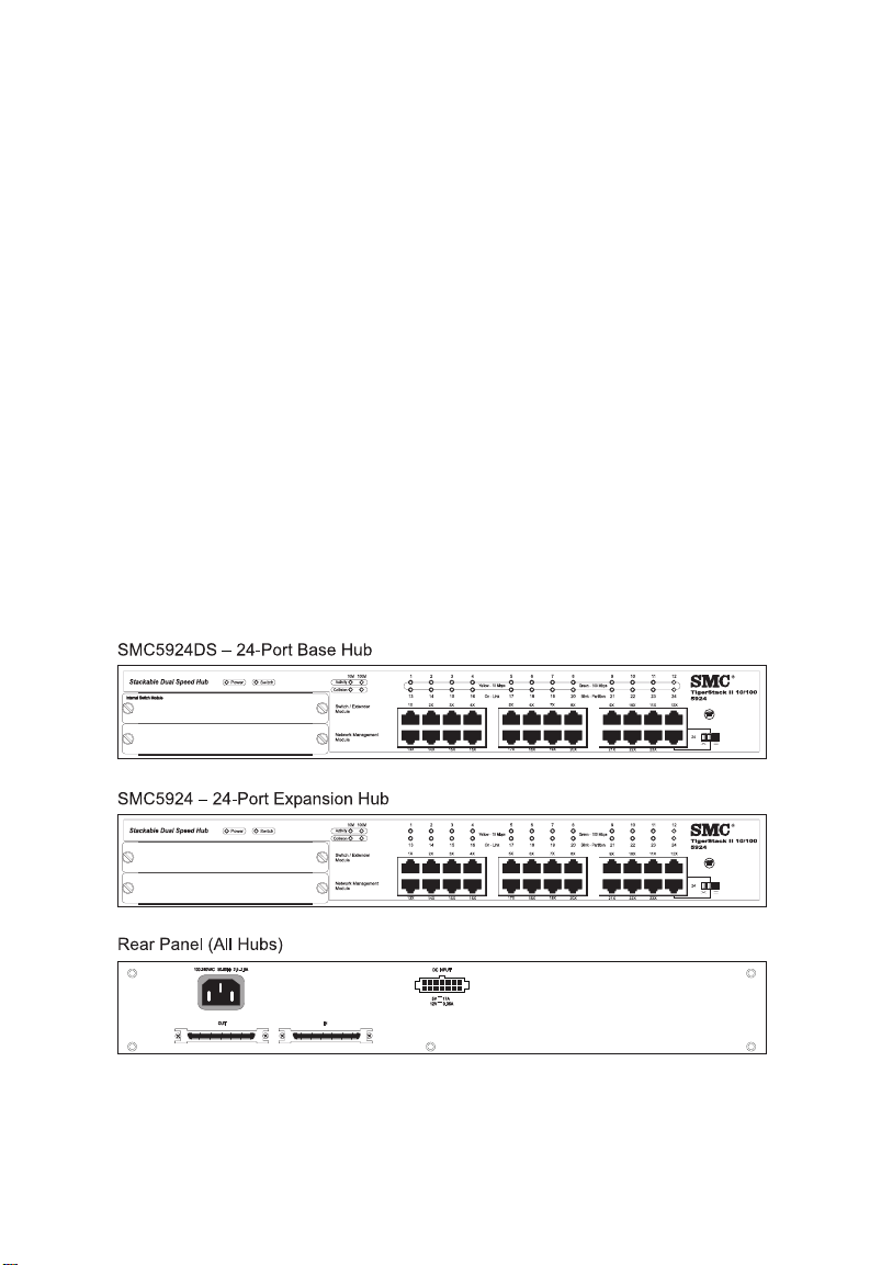
TigerStack II 10/100 hubs are available in four different models.
Each has either 12 or 24 10BASE-T/100BASE-TX ports plus two
front-panel slots for slide-in modules:
- SMC5912DS—12-port Base Hub preconfigured with Internal
Switch Module
- SMC5924DS—24-port Base Hub preconfigured with Internal
Switch Module
- SMC5912—12-port Expansion Hub
- SMC5924—24-port Expansion Hub
Figure 1-1. Front and Rear Panels of the SMC5924DS, and
SMC5924
1-2
Page 14
A
BOUT THE HUBS
The DS model Base Hubs are preconfigured with an Internal
Switch Module, and the Network Management Module can be
added as an option. Expansion Hubs come without any
preconfigured modules and can accept a variety of optional
Extender Modules. The Extender Modules provide a switched link
connection to the hub stack using either one 10BASE-T/
100BASE-TX port, one 100BASE-FX port, or one 10BASE2 BNC or
AUI connector. The 100BASE-FX Extender Modules are available
with SC or ST connectors.
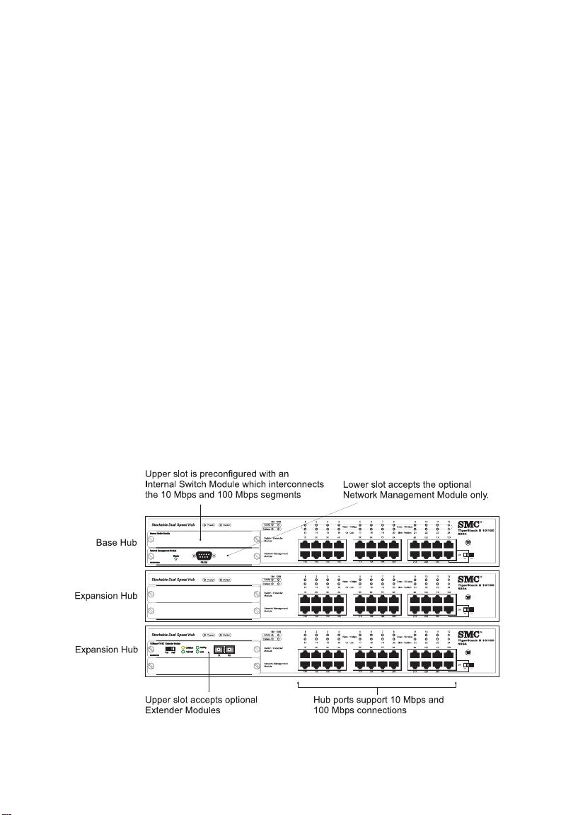
The Base Hubs can be used in a standalone configuration to
provide connectivity between 10 Mbps and 100 Mbps devices.
You can build a stack with just one Base Hub and up to five
Expansion Hubs to form a logical hub with up to 144 ports (see
Figure 1-2 below). Each port can be connected to either a 10
Mbps or 100 Mbps device. Ports automatically sense the speed of
an attached device and channel data to the appropriate 10 Mbps
or 100 Mbps segment. The Internal Switch Module in the Base
Hub supports communication between the two segments for all
hubs in the stack.
Figure 1-2. Stacking Base Hubs and Expansion Hubs
1-3
Page 15

A
BOUT THE HUBS
The hubs contain a comprehensive array of LEDs for “at-a-glance”
monitoring of network and port status. Also, if the Base Hub
contains a Network Management Module, the entire stack can be
managed in-band via SNMP, RMON (groups 1, 2, 3 and 9), or a
Web browser, as well as remotely via Telnet or SLIP. This module
also has a serial port for out-of-band management.
The hubs also provide a measure of fault tolerance. If two Network
Management Modules are installed in the stack, only the module
highest in the stack will be active; the Management Module in the
lower hub is placed in standby mode. The standby Management
Module will automatically take over if the active module fails. In
addition, the hub’s stack connections support an auto-bypass
feature. If any hub in a stack is powered off, data still passes
through the stack connections to all other hubs, so operation of
the rest of the stack remains uninterrupted. There’s also support
for a Redundant Power Unit to ensure continuous operation in the
event of a power failure.
Note: Do not install more than two Network Management
Modules in a stack.
1-4
Page 16
A
How to Use this Guide
Please read Chapters 1 through 4 when installing the TigerStack II
10/100 hubs. If you have added a Network Management Module
to one of the hubs as an option, also read the Advanced Reference
Guide (included with this module) to learn how to manage your
network.
Twisted-Pair Ports
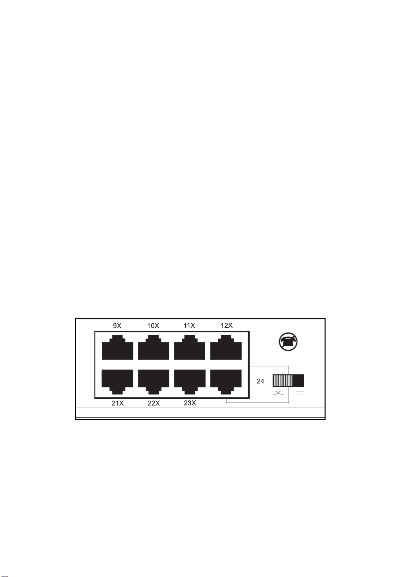
The RJ-45 ports are located on the front panel of each hub. Ports 1
through 11 on the 12-port models and 1 through 23 on the 24-port
models are labeled with an “x” to indicate that they have a built-in
crossover. Workstations and servers can be connected to these
ports with straight-through cable. The last port on each hub, port
12 or 24, is switch-selectable. There is an associated switch that is
used to enable and disable the crossover, so these ports can always
be connected to another hub or switch with straight-through cable.
BOUT THE HUBS
Figure 1-3. Twisted-Pair Ports
1-5
Page 17
A
BOUT THE HUBS
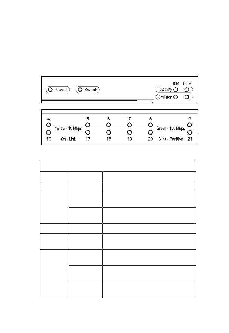
Status LEDs
The hub status LEDs are shown below and described in the
following table.
Figure 1-4. Port and Hub Status LEDs
DELnoitidnoCsutatS
rewoPnO.rewopgniviecersibuH
sDELsutatSbuHdnatroP
1-6
hctiwSnOhctiwslanretnis'eludomdellatninA
ffOhctiwslanretninahtiweludomA
ytivitcAgnihsalF.tnemgesehtnostsixeciffarT
noisilloCgnihsalFotdetpmettasecivederomroowT
/kniL
noititraP
neerGspbM001dilavadehsilbatsesahtroP
wolleYspbM01dilavadehsilbatsesahtroP
gnihsalFlamronbanaoteuddenoititraptroP
.evitcasinoitcnuf
.evitcanisirodellatsnitonsinoitcnuf
.emitemasehttaatadtimsnart
.noitcennoc
.noitcennoc
.noitidnockrowten
Page 18

A
Internal Switch Module
Figure 1-5. Internal Switch Module
Located in the top expansion slot of the DS hub models, the
Internal Switch Module interconnects the 10 Mbps and 100 Mbps
segments and employs a buffered store-and-forward architecture to
prevent bad packets from being propagated throughout the
network. It also features a non-blocking design that allows
simultaneous wire-speed transport in both directions at consistently
low latency.
A MAC address table that can hold 4K entries is provided for
learning, filtering and forwarding. Addresses are automatically
learned and maintained in the address table to enable the switch to
perform filtering and forwarding at line-rate speeds. When a
packet is encountered containing a destination address that does
not appear in the table, the packet is broadcast to both segments.
BOUT THE HUBS
If more than one Internal Switch Module or Extender Switch
Module is in a stack, only the internal switch function
(interconnecting the 10 and 100 Mbps segments) that is in the
module highest in the stack will be active; the internal switch
function in all other modules is disabled automatically. Note that if
the active internal switch function should fail, the stack needs to
be reset for another module’s internal switch function to become
active.
1-7
Page 19

A
BOUT THE HUBS
Optional Network Management Module
Figure 1-6. Network Management Module
As an option, a Network Management Module can be inserted into
the bottom slot of any hub model to manage the entire stack. It
offers a variety of management options, including SNMP, RMON
and a web-based interface. The management features are
described in the Advanced Reference Guide included in the
Network Management Module package.
This module also includes an RS-232 port for out-of-band
management and a Master LED which is described below.
DELretsaM
NO.edomevitcanisieludoM
FFO.)evitcani(edomybdnatsnisieludoM
A stack can support two Network Management Modules. The
module highest in a stack is active and the other module is placed
in standby mode. The standby module automatically takes over if
the active module fails.
Note: Do not install more than two Network Management
Modules in a stack.
1-8
Page 20
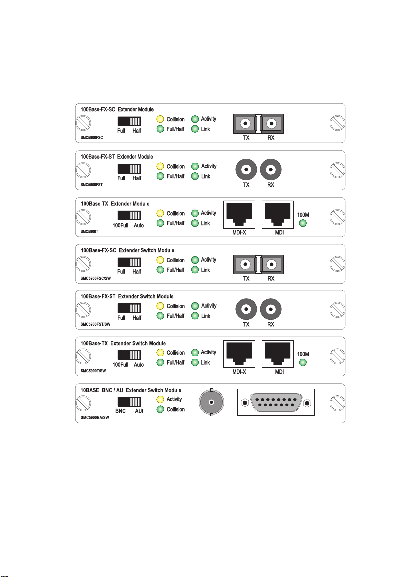
Optional Extender Modules
A
BOUT THE HUBS
Figure 1-7. Optional Extender Modules
There are seven Extender Modules to choose from. Each provides
a switched link from the stack’s 100 Mbps segment that can be
used to extend the size and reach of the stack. The Extender
Switch Modules also include the internal switch function to
interconnect the 10 Mbps and 100 Mbps segments.
1-9
Page 21

A
BOUT THE HUBS
- SMC5900T—one external 10BASE-T/100BASE-TX port, choice
of crossover or daisy-chain connection
- SMC5900FSC—one external 100BASE-FX port with SC
connectors
- SMC5900FST—one external 100BASE-FX port with ST
connectors
- SMC5900T/SW—one external 10BASE-T/100BASE-TX port,
choice of crossover or daisy-chain connection; plus internal
switch function
- SMC5900FSC/SW—one external 100BASE-FX port with SC
connectors; plus internal switch function
- SMC5900FST/SW—one external 100BASE-FX port with ST
connectors; plus internal switch function
- SMC5900BA/SW—one external switch-selectable BNC or AUI
port; plus internal switch function
The 10BASE-T/100BASE-TX port may be connected to an
Ethernet or Fast Ethernet device, such as a hub, workstation,
server or another switch. The port supports Auto-Negotiation, so
the optimum data rate and operating mode—10 or 100 Mbps and
half or full duplex—is selected automatically. However, if the
other device does not support Auto-Negotiation, the data rate and
operating mode can be forced to 100 Mbps full duplex via the
100Full/Auto toggle switch on the front of the module. Note that
if an attached device does not support Auto-Negotiation and
operates at 10 Mbps full duplex, then you can only configure the
module’s port to the correct settings using the Network
Management Module.
The 100BASE-FX port can be connected to a remote site with up
to 2 km (1.24 mi.) of fiber cable in full-duplex mode or up to
412 m (1,351.4 ft.) in half-duplex mode. The operating mode can
be set manually using the Full/Half toggle switch on the front of
the module. Note that this module operates only at 100 Mbps.
1-10
Page 22

A
sDELeludoMrednetxE
sDEL noitidnoC sutatS
flaH/lluFnO.xelpudlluftatessitroP
noisilloCgnihsalFotdetpmettasecivederomroowT
.emitemasehttaatadtimsnart
ytivitcAgnihsalF.atadgniviecerrognittimsnartsitroP
otlanoitroporpsignihsalffoetarehT
.ciffartkrowtenfotnuomaeht
kniLnOnodehsilbatseneebsahknildilavA
.tropsiht
M001nOT-ESAB01(spbM001tagnitarepositroP
.)ylnoeludomXT-ESAB001/
BOUT THE HUBS
The BNC and AUI ports allow connection to legacy 10 Mbps
network segments. The BNC port connects to 10BASE2 thin coax.
The AUI port can be connected to 10BASE5 thick coax or 10
Mbps fiber via an appropriate transceiver. The active port is
selected by the toggle switch on the front of the module.
1-11
Page 23

A
BOUT THE HUBS
Stacking Connectors
The stacking connectors are located on the rear panel of each hub.
Figure 1-8. Stacking Connectors
One connector is labeled “Out” and the other, “In.” A Stacking
Cable is shipped with each hub.
1-12
Page 24
A
BOUT THE HUBS
Optional Redundant Power Unit (RPU)
An RPU can supply power to the switch in the event of a failure of
the internal power supply. Contact your reseller for advice
regarding the appropriate SMC RPU for your specific application.
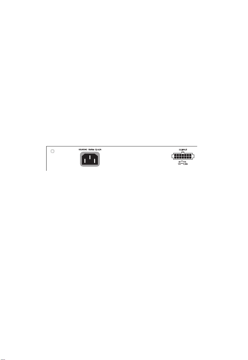
Power Supply Receptacles
There are two power receptacles on the rear panel of each hub.
The standard power receptacle is for the AC power cord. The
14-pin receptacle labeled “DC Input” is for the optional Redundant
Power Unit (RPU).
Figure 1-9. Rear Panel Receptacles
1-13
Page 25

A
BOUT THE HUBS
Features and Benefits
u
IEEE 802.3 Ethernet and 802.3u Fast Ethernet compliance
ensures compatibility with standards-based hubs, network cards
and switches from any vendor
u
Dual-speed ports for easy Fast Ethernet integration and for
protection of your investment in legacy LAN equipment
u
Auto-sensing enables each port to automatically determine the
speed of the attached device and channel the data to the
appropriate segment
u
Base Hubs preconfigured with a slide-in Internal Switch Module
to interconnect the 10 and 100 Mbps segments
u
Stackable six high
u
Scalable to 144 ports
u
Segmented into two collision domains (10 Mbps and 100
Mbps)
1-14
u
Choice of user-installable Extender Modules to overcome Fast
Ethernet distance limitations
u
Single Network Management Module manages entire stack inband or out-of-band
u
Complete network management set consisting of “at-a-glance”
LEDs, Telnet, SLIP, SNMP/RMON and Web-based interface
u
Fault-tolerant features include Network Management Module
redundancy and stack connection auto-bypass
u
Includes support for an optional Redundant Power Unit
u
Class II compliant at 100 Mbps
u
Switch-selectable port for crossover or daisy-chain connections
Page 26

u
Desktop or rack-mountable
u
Three-year warranty
A
BOUT THE HUBS
1-15
Page 27

A
BOUT THE HUBS
1-16
Page 28

CHAPTER 2
NETWORK PLANNING
Sample Applications . . . . . . . . . . . . . . . . . . . . 2-2
Integrating Fast Ethernet into an Ethernet LAN 2-2
Stacking the Hubs . . . . . . . . . . . . . . . . . . . 2-3
Extending the Stack . . . . . . . . . . . . . . . . . . 2-4
Connectivity Rules . . . . . . . . . . . . . . . . . . . . . 2-7
100 Mbps Fast Ethernet Collision Domain . . 2-7
10 Mbps Ethernet Collision Domain . . . . . . . 2-8
2-1
Page 29
N
ETWORK PLANNING
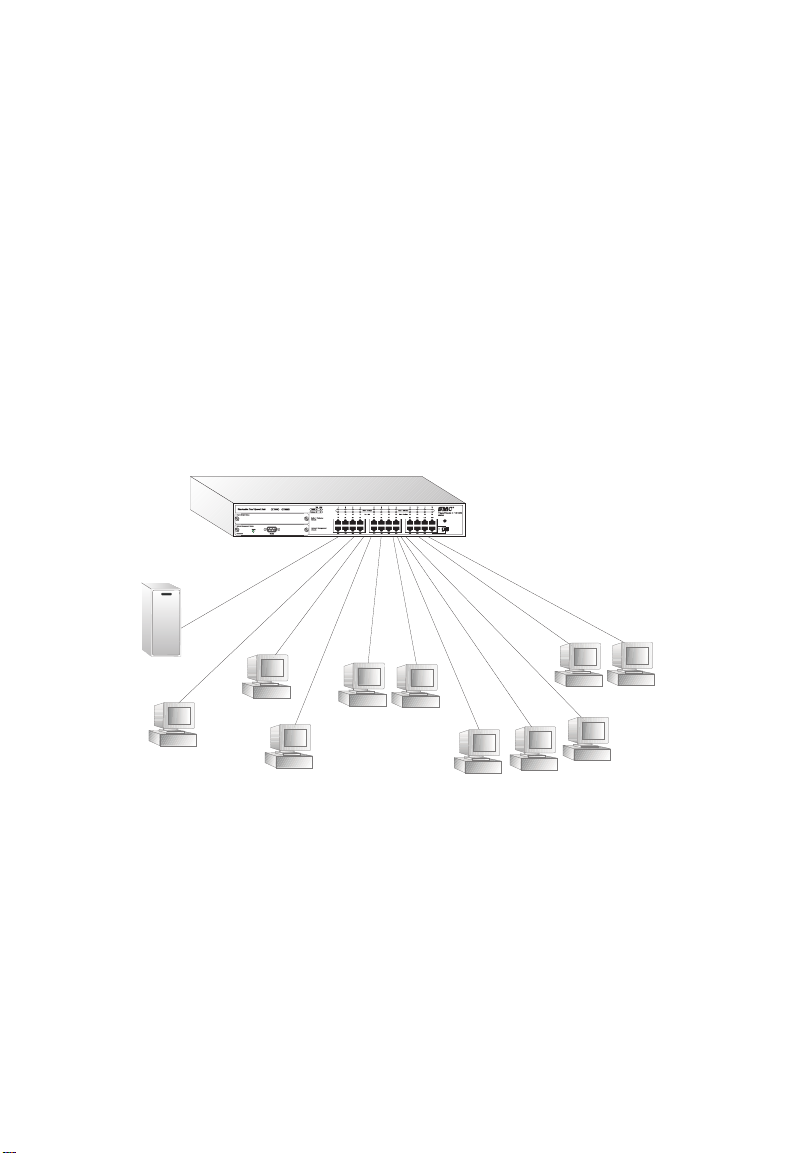
Sample Applications
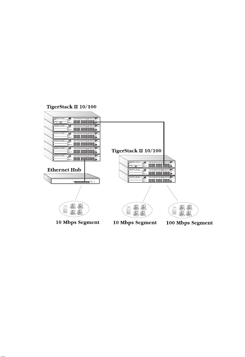
Integrating Fast Ethernet into an Ethernet Network
In the illustration below, a TigerStack II 10/100 Base Hub is used
standalone to integrate Fast Ethernet into an Ethernet network. The
Internal Switch Module, included in the Base Hubs, interconnects
the two segments to form a single LAN with an aggregate
bandwidth of 110 Mbps.
Note that for the Base Hub models, a Network Management
Module can be added at a later date.
Figure 2-1. Hub in a Standalone Configuration
2-2
Page 30

N
ETWORK PLANNING
Stacking the Hubs
Up to six hubs may be stacked, as shown below, to create a logical
hub with up to 144 ports. The stack requires only one Base Hub
(or Expansion hub with an optional Extender Switch Module
installed) and may include two optional Network Management
Modules.
Figure 2-2. Stack of Six Hubs Supporting 144 Ports
2-3
Page 31
N
ETWORK PLANNING
Extending the Stack
Since the TigerStack II 10/100 is a Class II hub, it may be cascaded
to a single Fast Ethernet hub or to a dual-speed hub. It may also be
cascaded to multiple Ethernet hubs as long as the SMC 5-4-3 Rule
is observed (see “Connectivity Rules” at the end of this chapter).
Figure 2-3. Extending a Stack to Other Hubs
2-4
Page 32

N
ETWORK PLANNING
Adding Extender Modules to the stack increases both the reach and
bandwidth of the network. In Figure 2-4, the same two stacks are
joined by a 10BASE-T/100BASE-TX Extender Module, instead of
being cascaded via front-panel ports, increasing the aggregate
bandwidth. A second 10BASE-T/100BASE-TX Extender Module is
used to provide a dedicated 200 Mbps connection to a server in
full-duplex mode.
Figure 2-4. Using 10/100 Extender Modules
2-5
Page 33

N
ETWORK PLANNING
The 100BASE-FX Extender Module is used for long distance
connections, as shown below.
Figure 2-5. Using a 100BASE-FX Extender Module
2-6
Page 34

Connectivity Rules
An overview of the rules for both Ethernet and Fast Ethernet
connectivity is provided below.
100 Mbps Fast Ethernet Collision Domain
SMC 3-2 Rule for Class II Repeaters
N
ETWORK PLANNING
:ebyamereht,niamodnoisilloc
dnastnemgesknil3otpu•
)sbuh(sretaeperIIssalC2otpu•
SMC 2-1 Rule for Class I Repeaters
:ebyamereht,niamodnoisilloc
dnastnemgesknil2otpu•
)buh(retaeperIssalC1otpu•
Maximum 100BASE-TX Network Diameter
epyTretaepeRriaPdetsiwT
rebmuNdnaXT-ESAB001
IssalC1).tf656(m002
IIssalC1).tf656(m002
IIssalC2).tf4.276(m502
Maximum Fast Ethernet Cable Distance
epyTelbaCgnitcennoCecnatsiD.xaM
riaPdetsiwTsecivedowtynA).tf823(m001
rebiFCProrevres,hctiwsothctiwS
xelpudflaH).tf4.153,1(m214
xelpudlluF).im42.1(mk2
XT-ESAB001emasehtnisnoitatsrehtorosCPowtynaneewteB
XT-ESAB001emasehtnisnoitatsrehtorosCPowtynaneewteB
2-7
Page 35

N
ETWORK PLANNING
10 Mbps Ethernet Collision Domain
SMC 5-4-3 Rule
:ebyamereht,niamod
,)sbuh(sretaeper4otpu•
Maximum Cable Length
epyTelbaChtgneLmumixaM
xaoCnihT).tf706(m581
porDreviecsnarTlanretxE).tf561(m05
noisillocspbM01emasehtnisnoitatsrehtorosCPowtynaneewteB
,seiresnistnemgesknil5otpu•
dehcattastnemges,sitaht,stnemgeselbacdetalupop3otpu•
*.)ylnoskrowtenxaoc(sCPeromroowtot
sanwonkeraeseht;detalupopnuerastnemgesowtgniniamerehT*
dnadetalupopneewtebnoitcnitsidsihT.sLRIrosknilretaeper-retni
.ylnoskrowtenxaocroftnacifingissistnemgesdetalupopnu
5,4,3seirogetaC,riaPdetsiwT).tf823(m001
2-8
Page 36

CHAPTER 3
INSTALLING THE STACK
Selecting a Site . . . . . . . . . . . . . . . . . . . . . . . . 3-2
Equipment Checklist . . . . . . . . . . . . . . . . . . . . 3-3
Hub Packing List . . . . . . . . . . . . . . . . . . . . 3-3
Optional Rack-Mounting Equipment . . . . . . 3-3
Mounting . . . . . . . . . . . . . . . . . . . . . . . . . . . . 3-4
Rack Mounting . . . . . . . . . . . . . . . . . . . . . 3-4
Desktop or Shelf Mounting . . . . . . . . . . . . . 3-6
Stacking . . . . . . . . . . . . . . . . . . . . . . . . . . . . 3-7
Connecting to a Power Source . . . . . . . . . . . . 3-8
3-1
Page 37

I
NSTALLING THE STACK
Selecting a Site
TigerStack II 10/100 hubs can be mounted in a standard 19-inch
equipment rack or on a flat surface. Be sure to follow the
guidelines below when choosing a location.
u
The site should:
• be able to maintain its temperature within 0° to 50° C and
its humidity within 0% to 90%, non-condensing
• provide adequate space (approximately two inches) on all
sides for proper air flow
• be accessible for installing, cabling and maintaining the
devices
• allow the status LEDs to be clearly visible
u
Make sure twisted-pair cable is always routed away from power
lines, fluorescent lighting fixtures and other sources of electrical
interference, such as radios, transmitters, etc.
u
Make sure that a separate grounded power outlet that provides
100 to 240 VAC, 50 to 60 Hz, is within 8 feet (2.44 m) of each
device and is powered from an independent circuit breaker. As
with any equipment, using a filter or surge suppressor is
recommended.
3-2
Page 38

I
NSTALLING THE STACK
Equipment Checklist
After unpacking the TigerStack II 10/100 products, check the
contents of each box against the included packing list to be sure
you’ve received all the components. Then, before beginning the
installation, be sure you have all the necessary equipment.
Hub Packing List
u
TigerStack II 10/100 hub
u
Four adhesive feet
u
Bracket Mounting Kit containing two brackets and four screws
for attaching the brackets to the hub
u
Stacking Cable
u
Power Cord—either US, Continental Europe or UK
u
This User Guide
u
SMC Warranty Registration Card—be sure to complete and
return to SMC
Optional Rack-Mounting Equipment
If you plan to rack-mount the hubs, be sure to have the following
equipment available:
u
Four mounting screws for each device you plan to install in a
rack—these are not included
u
A screwdriver (Phillips or flathead, depending on type of
screws used)
3-3
Page 39

I
NSTALLING THE STACK
Mounting
A TigerStack II 10/100 unit can be mounted in a standard 19-inch
equipment rack or on a desktop or shelf. Mounting instructions for
each type of site follow.
Before mounting the devices, be sure to install any optional
modules, as follows.
Installing Optional Hub Modules: If you have purchased
Network Management Modules and/or slide-in 100BASE-FX or -TX
Extender Modules, install the modules now, as needed, following
the instructions included with each package.
Rack Mounting
Before rack mounting the TigerStack II 10/100 devices, pay
particular attention to the following factors:
u
Temperature: Since the temperature within a rack assembly
may be higher than the ambient room temperature, check that
the rack-environment temperature is within the specified
operating temperature range.
3-4
u
Mechanical Loading: Do not place any equipment on top of
a rack-mounted unit.
u
Circuit Overloading: Be sure that the supply circuit to the
rack assembly is not overloaded.
u
Grounding: Rack-mounted equipment should be properly
grounded. Particular attention should be given to supply
connections other than direct connections to the mains.
Page 40

I
NSTALLING THE STACK
To rack-mount devices:
1. Attach the brackets to the device using the screws provided in
the Bracket Mounting Kit.
Figure 3-1. Attaching the Brackets
2. Mount the device in the rack, using four rack-mounting screws
(not provided).
Figure 3-2. Installing the Hub in a Rack
3-5
Page 41

I
NSTALLING THE STACK
3. If installing a single hub only, turn to “Connecting to a Power
Source” at the end of this chapter.
4. If installing multiple hubs, mount them in the rack, one below
the other, in any order.
5. If also installing RPUs, mount them in the rack below the other
devices.
Desktop or Shelf Mounting
1. Attach the four adhesive feet to the bottom of the first hub.
Figure 3-3. Attaching the Adhesive Feet
2. Set the device on a flat surface near an AC power source,
making sure there are at least two inches of space on all sides
for proper air flow.
3. If installing a single hub only, go to “Connecting to a Power
Source” at the end of this chapter.
4. If installing multiple hubs, attach four adhesive feet to each
one. Place each device squarely on top of the one below, in
any order.
5. If also installing RPUs, place them close to the stack.
3-6
Page 42

I
NSTALLING THE STACK
Stacking
A stack may have as many as six hubs.
Note: Be sure to have one stacking cable for each device you
plan to stack. A stacking cable is included with each hub.
Caution: DO-NOT stack SMC’s 10 Mbps TigerStack hubs with
SMC’s TigerStack II 10/100 hubs. If you attempt to do
so, the hubs will be damaged.
To stack the devices:
1. Locate the SCSI connectors labeled “IN” and “OUT” on the rear
of each device (see Figure 3-4).
2. Attach one end of the stacking cable to the SCSI connector
labeled “OUT” on the top device, and the other end to the
connector labeled “IN” on the next lower device.
3. Repeat this step until all the devices have been connected.
4. Turn to the next section, “Connecting to a Power Source.”
Figure 3-4. Stacking the Hubs
3-7
Page 43
I
NSTALLING THE STACK
Connecting to a Power Source
Note: It is recommended that the hubs be stacked before being
connected to a power source. However, a device can be
added to the top or bottom of a stack that is on and operating without first powering down the stack. Be sure to stack
the new device before connecting it to a power source.
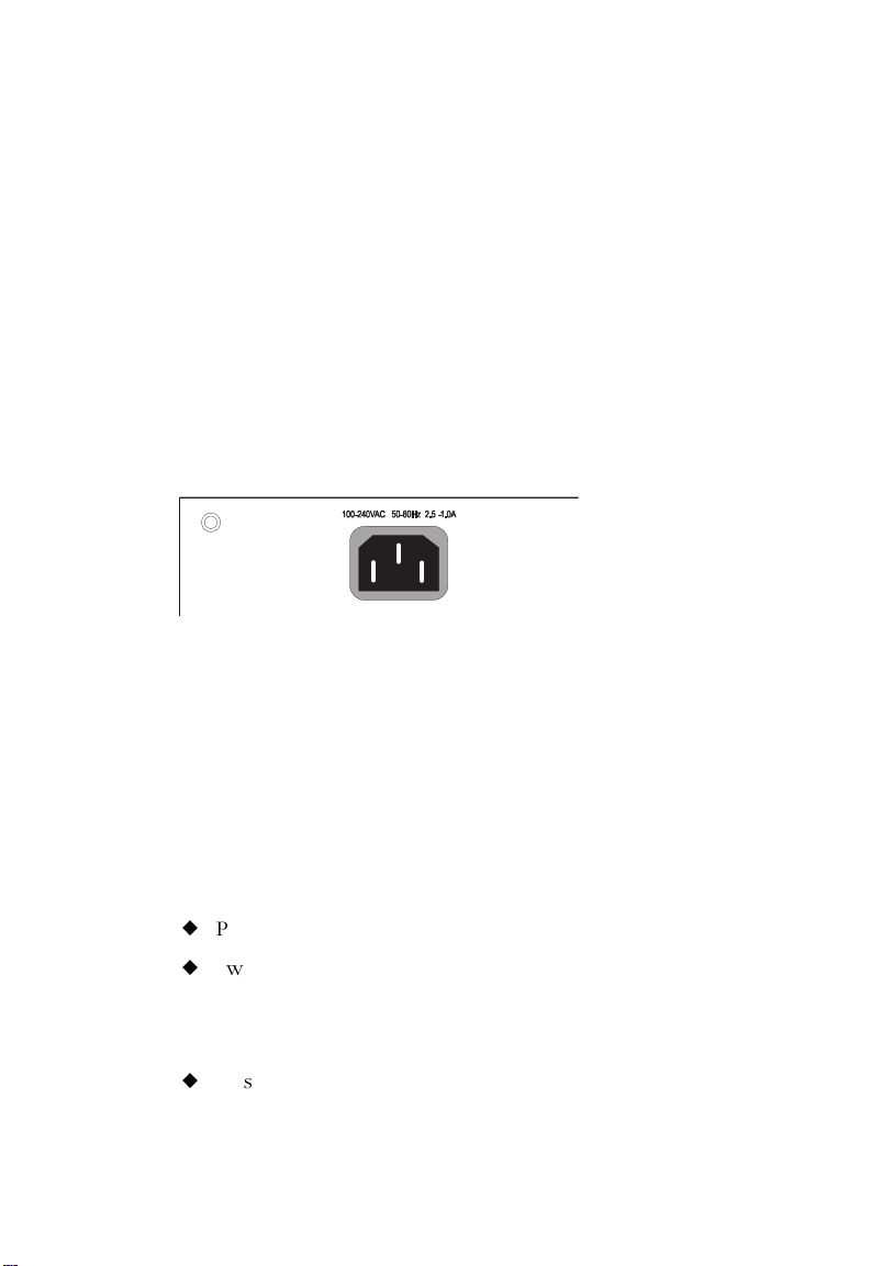
To connect each device to a power source:
1. Insert the power cable plug directly into the receptacle located
at the back of the device.
Figure 3-5. Power Receptacle
2. Plug the other end of the cable into a grounded, 3-pin socket.
Note: For International use, you may need to change the AC line
cord. You must use a line cord set that has been approved
for the receptacle type in your country.
3. Check the front-panel LEDs as each device is powered on.
On the hub, the following LEDs should light:
u
Power LED—green
u
Switch LED (if a Switch Module is installed)—green
On one Network Management Module, the following LED
should light:
u
Master LED—green
3-8
Page 44

I
NSTALLING THE STACK
4. If you have purchased Redundant Power Units, connect them
to the other devices and to an AC power source now, following
the instructions included with the package.
3-9
Page 45

I
NSTALLING THE STACK
3-10
Page 46

CHAPTER 4
MAKING NETWORK
CONNECTIONS
Connecting Network Devices . . . . . . . . . . . . . 4-2
Twisted-Pair Devices . . . . . . . . . . . . . . . . . . . 4-2
Cabling Guidelines . . . . . . . . . . . . . . . . . . . 4-2
Connecting to PCs, Servers, Hubs and
Switches . . . . . . . . . . . . . . . . . . . . . . . . 4-3
Wiring Closet Connections . . . . . . . . . . . . . 4-4
100BASE-FX Devices . . . . . . . . . . . . . . . . . . . 4-5
10BASE2 and AUI Connections . . . . . . . . . . . . 4-6
4-1
Page 47

M
AKING NETWORK CONNECTIONS
Connecting Network Devices
The TigerStack II 10/100 hubs may be connected to 10 and 100
Mbps network cards in PCs and servers, as well as to Ethernet and
Fast Ethernet switches and routers.
Twisted-Pair Devices
Each device requires an unshielded twisted-pair (UTP) cable with
RJ-45 connectors at both ends. For 100BASE-TX connections,
Category 5 cable is required; for 10BASE-T, Category 3, 4 or 5
cable can be used.
Cabling Guidelines
Every twisted-pair connection must have a wiring crossover to
transmit and receive data. For convenience, this crossover is built
into all ports that are labeled with an “x”—these are fixed crossover
ports. Since network cards do not have a built-in wiring crossover,
PCs can be connected to these ports with straight-through cable.
10BASE-T/100BASE-TX hubs and switches, on the other hand, may
have either crossover or straight-through ports. For this reason,
ports 12 or 24 on the TigerStack II 10/100 hubs are not labeled
with an “x”—these are switch-selectable crossover ports. The
associated Crossover switches (see Figure 4-1) are used to enable
and disable the wiring crossover on these ports. This way, hubs and
switches can always be connected to the TigerStack hubs with
straight-through cable.
Alternatively, you can connect from any crossover port on a
TigerStack hub to a straight-through port on another device. You
may also connect to crossover ports at both ends if you use a
crossover cable. See the following table and Appendix B for
further information.
4-2
Page 48
M
AKING NETWORK CONNECTIONS
ehtnotropehtfI
...sibuh
)x(revossorCrevossorCrevossorC
)x(revossorChguorht-thgiartShguorht-thgiartS
)=(hguorht-thgiartSrevossorChguorht-thgiartS
)=(hguorht-thgiartShguorht-thgiartSrevossorC
ehtnotropehtdnA
...siecivedrehto
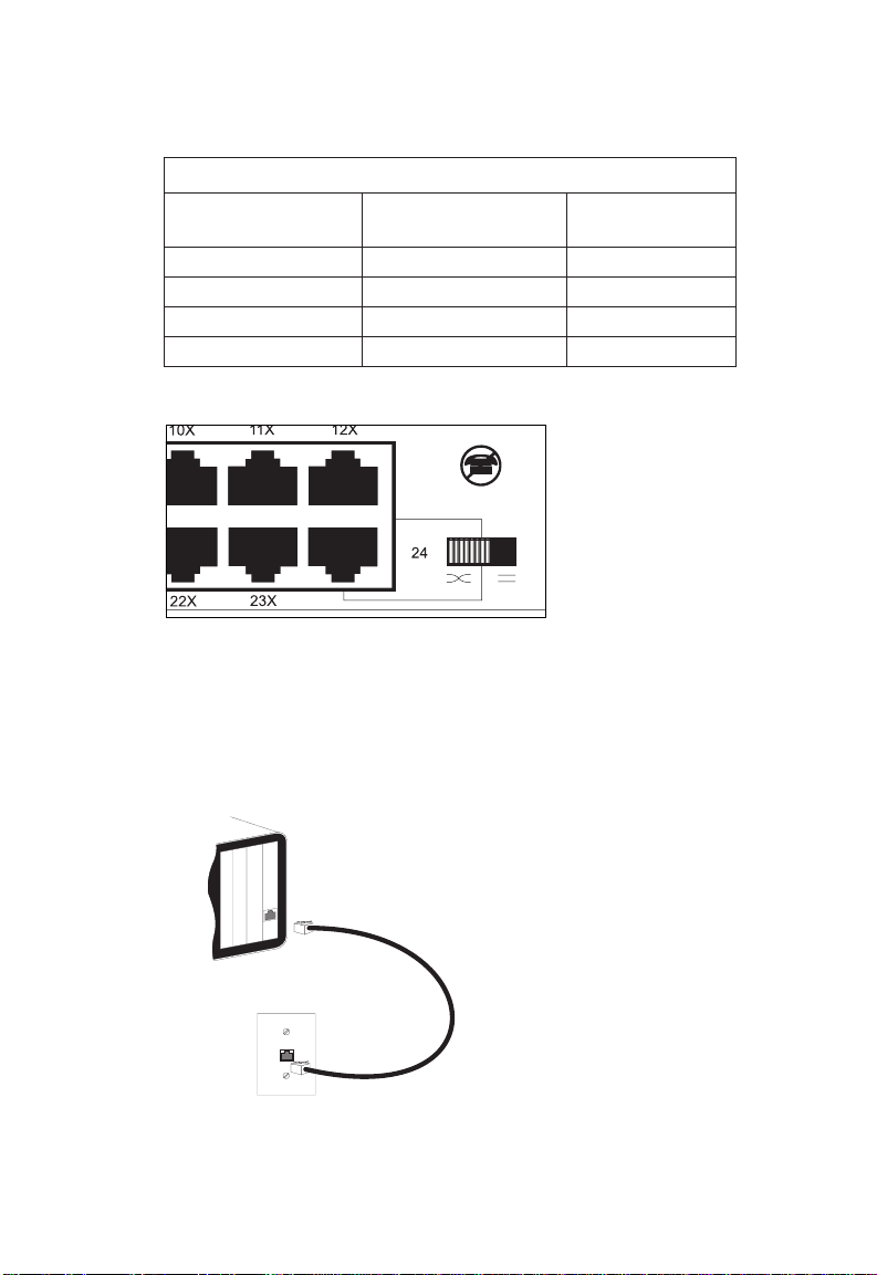
Figure 4-1. Crossover Switch on the 24-Port Hub
Connecting to PCs, Servers, Hubs and Switches
stnemeriuqeRgniriWhguorhT-thgiartS/revossorC
elbac...esunehT
1. Attach one end of a twisted-pair cable segment to the device’s
RJ-45 connector.
Figure 4-2. Making Twisted-Pair Connections
4-3
Page 49

M
AKING NETWORK CONNECTIONS
2. If the device is a network card and the TigerStack II 10/100 is
in the wiring closet, attach the other end of the cable segment
to a modular wall outlet that is connected to the wiring closet
(see “Wiring Closet Connections” on the next page). Otherwise,
attach the other end to an available port on the hub.
3. If the device is a hub or switch, attach the other end to the
appropriate port on the hub (port 12 or 24).
Wiring Closet Connections
Today, the punch-down block is an integral part of many of the
newer equipment racks. It is actually part of the patch panel.
Instructions for making connections in the wiring closet with this
type of equipment follows.
1. Attach one end of a patch cable to an available port on the
hub, and the other end to the patch panel.
2. If not already in place, attach one end of a cable segment to
the back of the patch panel where the punch-down block is
located, and the other end to a modular wall outlet.
3. Label the cables to simplify future troubleshooting.
4-4
Page 50

M
AKING NETWORK CONNECTIONS
Figure 4-3. Wiring Closet Connections
100BASE-FX Devices
If a slide-in 100BASE-FX module is present, its fiber port may be
used for backbone and longer distance connections.
Each 100BASE-FX device requires 62.5/125 or 50/125 micron
multimode fiber optic cabling with an SC or ST connector at both
ends.
For ST fiber ports, be sure to connect the Tx (Rx) connector on
the slide-in module to the Rx (Tx) connector on the other device.
For SC fiber ports, connect one end of the cable to the SC
connector on the slide-in module and the other end to the SC
connector on the other device. Since SC connectors are keyed, the
cable can be attached to the two devices in only one manner.
4-5
Page 51

M
AKING NETWORK CONNECTIONS
10BASE2 and AUI Connections
If the slide-in BNC/AUI Extender Switch Module is present, then
there are options for connecting to legacy 10 Mbps segments.
The toggle switch on the module’s front panel selects either the
BNC or AUI port.
The BNC connector provides a connection to 10BASE2 thin coax.
Attach the BNC T-connector to the BNC port, then connect one
side of the T-connector to a length of thin coax cable. The other
side of the T-connector should be connected to another length of
thin coax or a 50-ohm BNC terminator.
A thin coax segment can be up to 185 meters (607 feet) in length
and support up to 30 devices. Devices must be a minimum of 0.5
meters (2 feet) apart and the segment must be terminated at both
ends by a 50-ohm BNC terminator.
The AUI port can support connections to 10BASE5 thick coax, 10
Mbps fiber, or other 10 Mbps media via an appropriate
transceiver. Attach one end of a drop cable, maximum length 50
meters (165 feet), to the AUI port and the other end to the
transceiver.
4-6
Page 52

APPENDIX A
TROUBLESHOOTING
Troubleshooting LED Indicators . . . . . . . . . . . A-2
Power and Cooling Problems . . . . . . . . . . . . . A-3
A-1
Page 53

T
ROUBLESHOOTING
Troubleshooting LED Indicators
trahCgnitoohselbuorT
motpmySnoitcA
ffOsiDELrewoPehtneewtebsnoitcennocehtkcehC•
.ecivedrehtonarof
.lenaphctapdnakcolb
deRsiDELrewoPylppusrewoptnadnuderrolanretnI•
.teltuollawehtdnadrocrewopeht,buh
tignisuybteltuorewopehtkcehC•
kcehc,kcaranidellatsnisibuhehtfI•
nwod-hcnupehtotsnoitcennoceht
.troppuShceTCMStcatnoC•
.detcennocsidsirodeliafsah
A-2
DELytivitcA/kniL
ffOsi
.yrassecen
.noderewophtobera
.secivedhtobot
.)teef823(sretem001
.stcefedrofsnoitcennoc
eciveddehcattadnabuhehttahtkcehC•
detcennocsielbackrowtenehteruseB•
rofdesusielbac5yrogetaCtahtyfireV•
ehttahtdnasnoitcennocspbM001
deecxetonseodelbacynafohtgnel
elbacdnadrackrowtenehtkcehC•
fielbacrodracevitcefedehtecalpeR•
Page 54

Power and Cooling Problems
If the Power LED does not turn on when the power cord is
plugged in, you may have a problem with the power outlet or
power cord as explained in the troubleshooting chart. However, if
the unit powers off after running for a while, check for loose
power connections, power losses or surges at the power outlet,
and verify that the fans on the side of the unit are unobstructed
and running prior to shutdown. If you still cannot isolate the
problem, then the internal power supply may be defective. In this
case, contact your SMC dealer or reseller for assistance.
T
ROUBLESHOOTING
A-3
Page 55

T
ROUBLESHOOTING
A-4
Page 56

APPENDIX B
CABLES
Specifications . . . . . . . . . . . . . . . . . . . . . . . . . B-2
Twisted-Pair Cable and Pin Assignments . . . . . B-3
100BASE-TX/10BASE-T Pin Assignments . . . B-4
Straight-Through 100BASE-TX/
10BASE-T Wiring . . . . . . . . . . . . . . . . B-4
Crossover 100BASE-TX/
10BASE-T Wiring . . . . . . . . . . . . . . . . B-4
B-1
Page 57

C
ABLES
Specifications
epyTelbaCyrogetaCrotcennoC
elbaC)XT-ESAB001(riaP-detsiwT
GWA62-22,PTUmho-001
sriap2,mm6.0-4.0
epyTelbaCyrogetaCrotcennoC
GWA62-22,PTUmho-001
sriap2,mm6.0-4.0
epyTelbaCrotcennoC
epyTelbaCrotcennoC
U/C85-GRroU/A85-GRCNB
5
deifitrec
elbaC)T-ESAB01(riaP-detsiwT
5,4,354-JRnip-8,elam
erocnorcim521/05ro521/5.26TSroCS
elbaC)2ESAB01(xaoCnihT
54-JRnip-8,elam
elbaC)XF-ESAB001(rebiFedomitluM
elbaC)IUA(porDreviecsnarTlanretxE
B-2
epyTelbaCrotcennoC
PTSmho-87epyt-Dnip-51
Page 58
C
ABLES
Twisted-Pair Cable and Pin Assignments
Caution: DO-NOT plug a phone jack connector into any RJ-45
port. Use only twisted-pair cables with RJ-45 connectors
that conform with FCC standards.
For 100BASE-TX/10BASE-T connections, a twisted-pair cable must
have two pairs of wires. Each wire pair is identified by two
different colors. For example, one wire might be red and the other,
red with white stripes. Also, an RJ-45 connector must be attached
to both ends of the cable.
Caution: Each wire pair must be attached to the RJ-45 connectors
in a specific orientation (See “Twisted-Pair Cabling
Guidelines” in Chapter 4 for an explanation.)
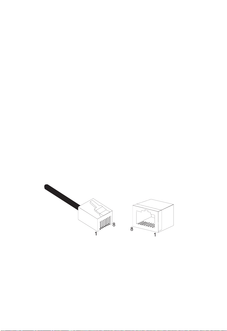
Figure B-1 illustrates how the pins on the RJ-45 connector are
numbered. Be sure to hold the connectors in the same orientation
when attaching the wires to the pins.
Figure B-1. RJ-45 Connector Pin Numbers
B-3
Page 59

C
ABLES
100BASE-TX/10BASE-T Pin Assignments
With 100BASE-TX/10BASE-T cable, pins 1 and 2 are used for
transmitting data, and pins 3 and 6 for receiving data.
stnemngissAniP54-JR
rebmuNniP*tnemngissA
1+xT
2-xT
3+xR
6-xR
* The “+” and “-” signs are used to represent the polarity of the wires
that make up each wire pair.
Straight-Through 100BASE-TX/10BASE-T Wiring
If the twisted-pair cable is to join two ports and only one of the
ports has an internal crossover, the two pairs of wires must be
straight-through.
B-4
stnemngissAniP54-JRhguorhT-thgiartS
1dnE2dnE
)+xT(1)+xT(1
)-xT(2)-xT(2
)+xR(3)+xR(3
)-xR(6)-xR(6
Page 60

C
ABLES
Crossover 100BASE-TX/10BASE-T Wiring
If the twisted-pair cable is to join two ports and either both ports
are labeled with an “x” or neither port is labeled with an “x,” a
crossover must be implemented in the wiring.
stnemngissAniP54-JRrevossorC
1dnE2dnE
)+xT(1)+xR(3
)-xT(2)-xR(6
)+xR(3)+xT(1
)-xR(6)-xT(2
B-5
Page 61

C
ABLES
B-6
Page 62

APPENDIX C
SPECIFICATIONS
12-Port TigerStack II 10/100 Hubs . . . . . . . . . . C-2
24-Port TigerStack II 10/100 Hubs . . . . . . . . . . C-2
All TigerStack II 10/100 Hubs . . . . . . . . . . . . . C-3
Slide-In Modules . . . . . . . . . . . . . . . . . . . . . . C-5
Internal Switch Module and All Extender
Switch Modules . . . . . . . . . . . . . . . . . . . C-5
100BASE-TX Extender Modules . . . . . . . . . . C-5
100BASE-FX Extender Modules . . . . . . . . . . C-6
BNC/AUI Extender Module . . . . . . . . . . . . . C-7
Network Management Module . . . . . . . . . . C-7
C-1
Page 63

S
PECIFICATIONS
12-Port TigerStack II 10/100 Hubs
SMC5912, or SMC5912DS
Ports
12 10BASE-T or 100BASE-TX
Interface
RJ-45 connectors, fixed crossover
Port 12 on hub only: switch-selectable crossover
Segments/Unit
Two, 10 Mbps and 100 Mbps
Weight
9.92 lb. (4.5 kg)
24-Port TigerStack II 10/100 Hubs
SMC5924, or SMC5924DS
Ports
24 10BASE-T or 100BASE-TX
Interface
RJ-45 connectors, fixed crossover
Port 24 on hub only: switch-selectable crossover
Segments/Unit
Two, 10 Mbps and 100 Mbps
Weight
9.92 lb. (4.5 kg)
C-2
Page 64

All TigerStack II 10/100 Hubs
Type
Class II
Network Interface
100BASE-TX: Category 5 UTP, 2 pairs
10BASE-T: Categories 3, 4, 5 UTP, 2 pairs
Size
17.32 x 7.87 x 2.48 in.
(44.0 x 20.0 x 6.3 cm)
LEDs
Power
Switch
Collision - one per segment
Link/Partition - one per port
Activity - one per segment
Switches
Crossover - one
Connectors
Stacking, 68-pin - two
DC Input for RPU, 14-pin
Temperature
Operating: 32° to 104° F (0° to 40° C)
Storage: -40° to 158° F (-40° to 70° C)
Humidity
Operating: 5% to 95%
AC Input
100 to 240 V, 50 to 60 Hz
Power Supply
Internal, auto-ranging transformer: 100 to 240 VAC, 50 to 60 Hz
Redundant DC input
S
PECIFICATIONS
C-3
Page 65

S
PECIFICATIONS
Power Consumption
50 Watts maximum
Heat Dissipation
170.5 BTU/hr maximum
Maximum Current
0.36A @ 110 VAC
0.22A @ 240 VAC
Standards
IEEE 802.3 Ethernet, 802.3u Fast Ethernet
ISO/IEC 8802-3
Compliances
CE Mark
Safety
UL 1950
CSA 22.2.950
EN60950 (TÜV)
Emissions
FCC Class A
EN55022 (CISPR 22) Class A
VCCI Class A
Immunity
IEC 1000-4-2/3/4/6
Warranty
Unit
Three years
C-4
Page 66

S
PECIFICATIONS
Slide-In Modules
Internal Switch Module and All Extender Switch
Modules
Models
SMC5900T/SW, SMC5900FSC/SW, SMC5900FST/SW,
SMC5900BA/SW
Network Bridging Function
Filtering, forwarding and learning
Switch Method
Store-and-forward
Address Table
4K entries
Queue Buffer
1 Mbyte shared memory
Address Resolution
Via fast hashing scheme
Filtering Rate
14,880 pps at 10 Mbps, 148,800 pps at 100 Mbps
Forwarding Rate
14,880 pps at 10 Mbps, 148,800 pps at 100 Mbps
100BASE-TX Extender Modules
Models
SMC5900T, SMC5900T/SW
Ports
1 10BASE-T or 100BASE-TX
(crossover or straight-through connection)
Network Interface
100BASE-TX: Category 5 UTP, 2 pairs
10BASE-T: Categories 3, 4, 5 UTP, 2 pairs
C-5
Page 67

S
PECIFICATIONS
LEDs
Link
Activity
Collision
Full/Half
100M
Toggle Switch
100 Mbps full duplex/Auto-Negotiation
Standards
IEEE 802.3 Ethernet, 802.3u Fast Ethernet
ISO/IEC 8802-3
100BASE-FX Extender Modules
Models
SMC5900FSC, SMC5900FST, SMC5900FSC/SW, SMC5900FST/SW
Ports
1 100BASE-FX
Network Interface
SC or ST connector, 62.5/125 or 50/125 micron multimode
fiber cable
LEDs
Link
Activity
Collision
Full/Half
Toggle Switch
Full duplex/half duplex
Standards
802.3u Fast Ethernet
ISO/IEC 8802-3
C-6
Page 68

BNC/AUI Extender Module
Model
SMC5900BA/SW
Ports
1 10BASE2 BNC or AUI 15-pin D-type connector
(switch selectable)
Network Interface
10BASE2: Thin coax, RG-58A/U or RG-58C/U
AUI: External transceiver drop
LEDs
Activity
Collision
Toggle Switch
BNC/AUI
Standards
IEEE 802.3 Ethernet
ISO/IEC 8802-3
Network Management Module
S
PECIFICATIONS
Model
SMC5900NMM
Connectors
RS-232
LEDs
Master
In-Band Management
Telnet, SLIP, Web-based HTTP, or SNMP manager
Out-of-Band Management
RS-232 console port
Software Loading
TFTP in-band or XModem out-of-band
C-7
Page 69

S
PECIFICATIONS
SNMP Support
MIB II (RFC 1213), Multi-Segment Repeater MIB (RFC 2108),
Ethernet-Like MIB (RFC 1643), RMON MIB (RFC 1757), SMC’s
private MIB
RMON Support
Groups 1, 2, 3, 9 (Statistics, History, Alarm, Event)
C-8
Page 70

APPENDIX D
ORDERING INFORMATION
TigerStack II 10/100 Products & Accessories . . D-2
D-1
Page 71

O
RDERING INFORMATION
SD2195CMSlanretnIhtiwderugifnocerpbuHesaBtrop-21
SD4295CMSlanretnIhtiwderugifnocerpbuHesaBtrop-42
2195CMSbuHnoisnapxEtrop-21
4295CMSbuHnoisnapxEtrop-42
MMN0095CMSeludoMtnemeganaMkrowteN
CSF0095CMSCShtiweludoMrednetxEXF-ESAB001
TSF0095CMSTShtiweludoMrednetxEXF-ESAB001
T0095CMSeludoMrednetxEXT-ESAB001/01
seirosseccAdnastcudorP001/01IIkcatSregiT
rebmuNtcudorPnoitpircseD
eludoMhctiwS
eludoMhctiwS
rotcennoc
rotcennoc
WS/CSF0095CMSCShtiweludoMhctiwSrednetxEXF-ESAB001
noitcnufhctiwslanretnidnarotcennoc
WS/TSF0095CMSTShtiweludoMhctiwSrednetxEXF-ESAB001
noitcnufhctiwslanretnidnarotcennoc
WS/T0095CMShtiweludoMhctiwSrednetxEXT-ESAB001/01
noitcnufhctiwslanretni
WS/AB0095CMSlanretnihtiweludoMhctiwSrednetxEIUA/CNB
noitcnufhctiws
0.5weiVetilEerawtfostnemeganamkrowtendesab-PMNS
5XUPRCMS*selbachtiwtinUrewoPtnadnudeR
* Also available in models for Continental Europe and the UK.
D-2
Page 72

APPENDIX E
GLOSSARY
Glossary of Terms . . . . . . . . . . . . . . . . . . . . E-2
E-1
Page 73

G
LOSSARY
Glossary of Terms
10BASE-T
IEEE 802.3 specification for 10 Mbps Ethernet over two pairs of
Category 3, 4, or 5 UTP cable.
100BASE-FX
IEEE 802.3u specification for 100 Mbps Fast Ethernet over two
strands of 62.5/125 or 50/125 micron core fiber cable.
100BASE-TX
IEEE 802.3u specification for 100 Mbps Fast Ethernet over two
pairs of Category 5 UTP cable.
Auto-Negotiation
Signalling method allowing each node to select its optimum
operational mode (e.g., 10 Mbps or 100 Mbps and half or full
duplex) based on the capabilities of the node to which it is
connected.
Bandwidth
The difference between the highest and lowest frequencies
available for network signals. Also synonymous with wire speed—
the actual speed of the data transmission along the cable.
Bandwidth Utilization
The percentage of packets received over time as compared to
overall bandwidth.
E-2
Page 74

Class I Repeater
Fast Ethernet repeater that is principally used to connect different
physical signaling systems (e.g., 100BASE-TX, 100BASE-FX) and
that has an internal delay such that only one repeater of this type
can reside within a single collision domain when maximum cable
lengths are used.
Class II Repeater
Fast Ethernet repeater that typically supports a single physical
signaling system (e.g., 100BASE-TX, or 100BASE-FX) and that has a
smaller internal delay so that two such repeaters can reside within
a single collision domain when maximum cable lengths are used.
Collision Domain
Single CSMA/CD LAN segment.
Crossover Port
Twisted-pair port with a built-in wiring crossover.
G
LOSSARY
Fast Ethernet Switch
Device that provides a full 100 Mbps bandwidth (or either 10 or
100 Mbps bandwidth with Auto-Negotiation) to each port (LAN
segment).
Full Duplex
Transmission method that allows switch and network card to
transmit and receive concurrently, effectively doubling the
bandwidth of that link.
In-Band Management
Management of the network from a station that is attached to the
network.
E-3
Page 75

G
LOSSARY
LAN Segment
Separate LAN or collision domain.
Link Segment
Length of twisted-pair or fiber cable joining a pair of repeaters or a
repeater and a PC.
Network Diameter
Wire distance between two end stations in the same collision
domain.
Out-of-Band Management
Management of the network from a station that is not attached to
the network.
Segmentable Hub
Hub capable of subdividing the LAN into separate collision
domains.
Shared Ports
Ports that are on the same collision domain and share a fixed
bandwidth.
SLIP
Serial Line Internet Protocol, a standard protocol for point-to-point
connections using serial lines.
Stackable Hubs
Hubs that can be stacked to support additional users without
repeater hops—the entire stack counts as a single logical repeater.
E-4
Page 76

Switched Ports
Ports that are on separate collision domains or LAN segments.
UTP
Unshielded twisted-pair cable.
G
LOSSARY
E-5
Page 77

FOR TECHNICAL SUPPORT, CALL:
From U.S.A. and Canada (8:30 AM - 8:00 PM Pacific Time)
(800) SMC-4-YOU; (949) 707-2400; (949) 707-2460 (Fax)
From Europe (8:00 AM - 5:30 PM UK Greenwich Mean Time)
44 (0) 1344 420068; 44 (0) 1344 418835 (Fax)
INTERNET
E-mail addresses:
techsupport@smc.com
Driver updates:
http://www.smc.com/support.html
SMC Forum on CompuServe:
At the prompt (!) type: GO SMC
World Wide Web:
http://www.smc.com/
FTP Site:
ftp.smc.com
FOR LITERATURE OR ADVERTISING RESPONSE CALL:
U.S.A. and Canada: (800) SMC-4-YOU; Fax (949 ) 707-2460
Europe : 44 (0) 1344 418800; Fax 44 (0) 1344 418828
Norther n Europe: 44 (0) 1344 418820; Fax 44 (0) 1344 418826
Southern Europe: 33 (1) 41.38.32.32; Fax 33 (1) 41.38.01.58
Central/Eastern Europe: 49 (0) 89 92861-0; Fax 49 (0) 89 92861-230
Nordic: 46 (8) 564 33145; Fax 46 (8) 87 62 62
Middle East: 971-4818410; Fax 971-4817993
South Africa: 27 (0) 11-3936491; Fax 27 (0) 11-3936491
PRC: 86-10-6235-4958; Fax 86-10-6235-4962
Taiwan: 886-2-2748-3945; Fax 886-2-2748-3942
Asia Pacific: (65) 336 1800; Fax (65) 339 6625
Korea: 82- 2-553 -0860-1; Fax 82-2-553-7202-3
Japan: 81 (3) 57212271; Fax 81 (3) 57212270
Australia: 61-2-9416-0495; Fax 61-2-9416-0474
India: 91-22-8204437; Fax 91-22-8204443
6 Hughes
Irvine, CA 92618
Phone: (949) 707-2400
Publication Number: 150914-101 E0599-R02
 Loading...