

Page 1

USER GUIDE
SMC2555W-AG2
EliteConnectTM Universal
802.11a/g 2.4GHz/5GHz
Wireless Access Point
Page 2

EliteConnect™ SMC2555W-AG2
Universal 2.4GHz/5GHz Wireless
Dual-Band Access Point
The easy way to make all your network connections
20 Mason
Irvine, CA 92618
Phone: (949) 679-8000
October 2008
Pub.# 149100033500E
E102008-AP-R03
Page 3

Information furnished by SMC Networks, Inc. (SMC) is believed to be accurate and
reliable. However, no responsibility is assumed by SMC for its use, nor for any
infringements of patents or other rights of third parties which may result from its use. No
license is granted by implication or otherwise under any patent or patent rights of SMC.
SMC reserves the right to change specifications at any time without notice.
Copyright © 2008 by
SMC Networks, Inc.
20 Mason
Irvine, CA 92618
All rights reserved. Printed in Taiwan
Trademarks:
SMC is a registered trademark; and EZ Switch, TigerStack and TigerSwitch are
trademarks of SMC Networks, Inc. Other product and company names are trademarks or
registered trademarks of their respective holders.
Page 4

Limited Warranty
Limited Warranty Statement: SMC Networks, Inc. (“SMC”) warrants its products to be
free from defects in workmanship and materials, under normal use and service, for the
applicable warranty term. All SMC products carry a standard 90-day limited warranty from
the date of purchase from SMC or its Authorized Reseller. SMC may, at its own discretion,
repair or replace any product not operating as warranted with a similar or functionally
equivalent product, during the applicable warranty term. SMC will endeavor to repair or
replace any product returned under warranty within 30 days of receipt of the product.
The standard limited warranty can be upgraded to a Limited Lifetime* warranty by
registering new products within 30 days of purchase from SMC or its Authorized Reseller.
Registration can be accomplished via the enclosed product registration card or online via
the SMC Web site. Failure to register will not affect the standard limited warranty. The
Limited Lifetime warranty covers a product during the Life of that Product, which is
defined as the period of time during which the product is an “Active” SMC product. A
product is considered to be “Active” while it is listed on the current SMC price list. As new
technologies emerge, older technologies become obsolete and SMC will, at its discretion,
replace an older product in its product line with one that incorporates these newer
technologies. At that point, the obsolete product is discontinued and is no longer an
“Active” SMC product. A list of discontinued products with their respective dates of
discontinuance can be found at:
http://www.smc.com/index.cfm?action=customer_service_warranty.
All products that are replaced become the property of SMC. Replacement products may
be either new or reconditioned. Any replaced or repaired product carries either a 30-day
limited warranty or the remainder of the initial warranty, whichever is longer. SMC is not
responsible for any custom software or firmware, configuration information, or memory
data of Customer contained in, stored on, or integrated with any products returned to
SMC pursuant to any warranty. Products returned to SMC should have any
customer-installed accessory or add-on components, such as expansion modules,
removed prior to returning the product for replacement. SMC is not responsible for these
items if they are returned with the product.
Customers must contact SMC for a Return Material Authorization number prior to
returning any product to SMC. Proof of purchase may be required. Any product returned
to SMC without a valid Return Material Authorization (RMA) number clearly marked on
the outside of the package will be returned to customer at customer’s expense. For
warranty claims within North America, please call our toll-free customer support number
at (800) 762-4968. Customers are responsible for all shipping charges from their facility to
SMC. SMC is responsible for return shipping charges from SMC to customer.
WARRANTIES EXCLUSIVE: IF AN SMC PRODUCT DOES NOT OPERATE AS
WARRANTED ABOVE, CUSTOMER’S SOLE REMEDY SHALL BE REPAIR OR
REPLACEMENT OF THE PRODUCT IN QUESTION, AT SMC’S OPTION. THE
FOREGOING WARRANTIES AND REMEDIES ARE EXCLUSIVE AND ARE IN LIEU OF
ALL OTHER WARRANTIES OR CONDITIONS, EXPRESS OR IMPLIED, EITHER IN
FACT OR BY OPERATION OF LAW, STATUTORY OR OTHERWISE, INCLUDING
WARRANTIES OR CONDITIONS OF MERCHANTABILITY AND FITNESS FOR A
PARTICULAR PURPOSE. SMC NEITHER ASSUMES NOR AUTHORIZES ANY OTHER
PERSON TO ASSUME FOR IT ANY OTHER LIABILITY IN CONNECTION WITH THE
SALE, INSTALLATION, MAINTENANCE OR USE OF ITS PRODUCTS. SMC SHALL
iv
Page 5

NOT BE LIABLE UNDER THIS WARRANTY IF ITS TESTING AND EXAMINATION
DISCLOSE THE ALLEGED DEFECT IN THE PRODUCT DOES NOT EXIST OR WAS
CAUSED BY CUSTOMER’S OR ANY THIRD PERSON’S MISUSE, NEGLECT,
IMPROPER INSTALLATION OR TESTING, UNAUTHORIZED ATTEMPTS TO REPAIR,
OR ANY OTHER CAUSE BEYOND THE RANGE OF THE INTENDED USE, OR BY
ACCIDENT, FIRE, LIGHTNING, OR OTHER HAZARD.
LIMITATION OF LIABILITY: IN NO EVENT, WHETHER BASED IN CONTRACT OR
TORT (INCLUDING NEGLIGENCE), SHALL SMC BE LIABLE FOR INCIDENTAL,
CONSEQUENTIAL, INDIRECT, SPECIAL, OR PUNITIVE DAMAGES OF ANY KIND, OR
FOR LOSS OF REVENUE, LOSS OF BUSINESS, OR OTHER FINANCIAL LOSS
ARISING OUT OF OR IN CONNECTION WITH THE SALE, INSTALLATION,
MAINTENANCE, USE, PERFORMANCE, FAILURE, OR INTERRUPTION OF ITS
PRODUCTS, EVEN IF SMC OR ITS AUTHORIZED RESELLER HAS BEEN ADVISED
OF THE POSSIBILITY OF SUCH DAMAGES.
SOME STATES DO NOT ALLOW THE EXCLUSION OF IMPLIED WARRANTIES OR
THE LIMITATION OF INCIDENTAL OR CONSEQUENTIAL DAMAGES FOR
CONSUMER PRODUCTS, SO THE ABOVE LIMITATIONS AND EXCLUSIONS MAY
NOT APPLY TO YOU. THIS WARRANTY GIVES YOU SPECIFIC LEGAL RIGHTS,
WHICH MAY VARY FROM STATE TO STATE. NOTHING IN THIS WARRANTY SHALL
BE TAKEN TO AFFECT YOUR STATUTORY RIGHTS.
* SMC will provide warranty service for one year following discontinuance from the active
SMC price list. Under the limited lifetime warranty, internal and external power supplies,
fans, and cables are covered by a standard one-year warranty from date of purchase.
SMC Networks, Inc.
20 Mason
Irvine, CA 92618
v
Page 6

vi
Page 7

COMPLIANCES
Federal Communication Commission Interference
Statement
This equipment has been tested and found to comply with the limits for a Class B
digital device, pursuant to Part 15 of the FCC Rules. These limits are designed to
provide reasonable protection against harmful interference in a residential
installation. This equipment generates, uses and can radiate radio frequency
energy and, if not installed and used in accordance with the instructions, may
cause harmful interference to radio communications. However, there is no
guarantee that interference will not occur in a particular installation. If this
equipment does cause harmful interference to radio or television reception, which
can be determined by turning the equipment off and on, the user is encouraged to
try to correct the interference by one of the following measures:
• Reorient or relocate the receiving antenna
• Increase the separation between the equipment and receiver
• Connect the equipment into an outlet on a circuit different from that to which the
receiver is connected
• Consult the dealer or an experienced radio/TV technician for help
FCC Caution: Any changes or modifications not expressly approved by the party
responsible for compliance could void the user's authority to operate this
equipment. This device complies with Part 15 of the FCC Rules. Operation is
subject to the following two conditions: (1) This device may not cause harmful
interference, and (2) this device must accept any interference received, including
interference that may cause undesired operation.
IMPORTANT NOTE:
FCC Radiation Exposure Statement
This equipment complies with FCC radiation exposure limits set forth for an
uncontrolled environment. This equipment should be installed and operated with a
minimum distance of 20 centimeters (8 inches) between the radiator and your
body. This transmitter must not be co-located or operating in conjunction with any
other antenna or transmitter.
Wireless 5 GHz Band Statements:
As the Access Point can operate in the 5150-5250 MHz frequency band it is
limited by the FCC, Industry Canada and some other countries to indoor use only
so as to reduce the potential for harmful interference to co-channel Mobile
Satellite systems.
i
Page 8

COMPLIANCES
High power radars are allocated as primary users (meaning they have priority) of
the 5250-5350 MHz and 5650-5850 MHz bands. These radars could cause
interference and /or damage to the access point when used in Canada.
The term “IC” before the radio certification number only signifies that Industry
Canada technical specifications were met.
Industry Canada - Class B
This digital apparatus does not exceed the Class B limits for radio noise emissions
from digital apparatus as set out in the interference-causing equipment standard
entitled “Digital Apparatus,” ICES-003 of Industry Canada.
Cet appareil numérique respecte les limites de bruits radioélectriques applicables
aux appareils numériques de Classe B prescrites dans la norme sur le matérial
brouilleur: “Appareils Numériques,” NMB-003 édictée par l’Industrie.
Japan VCCI Class B
Australia/New Zealand AS/NZS 4771
ACN 066 352010
ii
Page 9

C
OMPLIANCES
EC Conformance Declaration
Marking by the above symbol indicates compliance with the Essential
Requirements of the R&TTE Directive of the European Union (1999/5/
EC). This equipment meets the following conformance standards:
• EN 60950-1 (IEC 60950-1) - Product Safety
• EN 301 893 - Technical requirements for 5 GHz radio equipment
• EN 300 328 - Technical requirements for 2.4 GHz radio equipment
• EN 301 489-1 / EN 301 489-17 - EMC requirements for radio equipment
Countries of Operation & Conditions of Use in the European
Community
This device is intended to be operated in all countries of the European
Community. Requirements for indoor vs. outdoor operation, license
requirements and allowed channels of operation apply in some countries
as described below:
Note: The user must use the configuration utility provided with this
product to ensure the channels of operation are in conformance
with the spectrum usage rules for European Community countries
as described below.
• This device requires that the user or installer properly enter the current
country of operation in the command line interface as described in the
user guide, before operating this device.
• This device will automatically limit the allowable channels determined
by the current country of operation. Incorrectly entering the country of
operation may result in illegal operation and may cause harmful
interference to other systems. The user is obligated to ensure the
device is operating according to the channel limitations, indoor/outdoor
restrictions and license requirements for each European Community
country as described in this document.
• This device employs a radar detection feature required for European
Community operation in the 5 GHz band. This feature is automatically
enabled when the country of operation is correctly configured for any
European Community country. The presence of nearby radar operation
may result in temporary interruption of operation of this device. The
radar detection feature will automatically restart operation on a channel
free of radar.
iii
Page 10

COMPLIANCES
• The 5 GHz Turbo Mode feature is not allowed for operation in any
European Community country. The current setting for this feature is
found in the 5 GHz 802.11a Radio Settings Window as described in the
user guide.
• The 5 GHz radio's Auto Channel Select setting described in the user
guide must always remain enabled to ensure that automatic 5 GHz
channel selection complies with European requirements. The current
setting for this feature is found in the 5 GHz 802.11a Radio Settings
Window as described in the user guide.
• This device is restricted to indoor use when operated in the European
Community using the 5.15 - 5.35 GHz band: Channels 36, 40, 44, 48,
52, 56, 60, 64. See table below for allowed 5 GHz channels by country.
• This device may be operated indoors or outdoors in all countries of the
European Community using the 2.4 GHz band: Channels 1 - 13, except
where noted below.
- In Italy the end-user must apply for a license from the national
spectrum authority to operate this device outdoors.
- In Belgium outdoor operation is only permitted using the 2.46 -
2.4835 GHz band: Channel 13.
- In France outdoor operation is only permitted using the 2.4 - 2.454
GHz band: Channels 1 - 7.
iv
Page 11

C
OMPLIANCES
Operation Using 5 GHz Channels in the European
Community
The user/installer must use the provided configuration utility to check the
current channel of operation and make necessary configuration changes
to ensure operation occurs in conformance with European National
spectrum usage laws as described below and elsewhere in this
document.
Allowed 5GHz Channels in Each European Community Country
Allowed Frequency Bands Allowed Channel Numbers Countries
5.15 - 5.25 GHz* 36, 40, 44, 48 Austria, Belgium
5.15 - 5.35 GHz* 36, 40, 44, 48, 52, 56, 60, 64 France,
5.15 - 5.35* & 5.470 - 5.725
GHz
5 GHz Operation Not
Allowed
* Outdoor operation is not allowed using 5.15-5.35 GHz bands (Channels 36 -
64).
36, 40, 44, 48, 52, 56, 60, 64,
100, 104, 108, 112, 116, 120,
124, 128, 132, 136, 140
None Greece
Switzerland,
Liechtenstein
Denmark, Finland,
Germany, Iceland,
Ireland, Italy,
Luxembourg,
Netherlands,
Norway, Portugal,
Spain, Sweden,
U.K.
v
Page 12

COMPLIANCES
Declaration of Conformity in Languages of the European
Community
English Hereby, SMC, declares that this Radio LAN device is in
Finnish Valmistaja SMC vakuuttaa täten että Radio LAN device tyyppinen
Dutch Hierbij verklaart SMC dat het toestel Radio LAN device in
French Par la présente SMC déclare que l'appareil Radio LAN device est
Swedish Härmed intygar SMC att denna Radio LAN device står I
Danish Undertegnede SMC erklærer herved, at følgende udstyr Radio
German Hiermit erklärt SMC, dass sich dieser/diese/dieses Radio LAN
Greek ΜΕ ΤΗΝ ΠΑΡΟΥΣΑ SMC ΔΗΛΩ ΝΕΙ ΟΤΙ radio LAN device
Italian Con la presente SMC dichiara che questo Radio LAN device è
compliance with the essential requirements and other relevant
provisions of Directive 1999/5/EC.
laite on direktiivin 1999/5/EY oleellisten vaatimusten ja sitä
koskevien direktiivin muiden ehtojen mukainen.
overeenstemming is met de essentiële eisen en de andere
relevante bepalingen van richtlijn 1999/5/EG
Bij deze SMC dat deze Radio LAN device voldoet aan de
essentiële eisen en aan de overige relevante bepalingen van
Richtlijn 1999/5/EC.
conforme aux exigences essentielles et aux autres dispositions
pertinentes de la directive 1999/5/CE
överensstämmelse med de väsentliga egenskapskrav och övriga
relevanta bestämmelser som framgår av direktiv 1999/5/EG.
LAN device overholder de væsentlige krav og øvrige relevante
krav i direktiv 1999/5/EF
device in Übereinstimmung mit den grundlegenden
Anforderungen und den anderen relevanten Vorschriften der
Richtlinie 1999/5/EG befindet". (BMWi)
Hiermit erklärt SMC die Übereinstimmung des Gerätes Radio
LAN device mit den grundlegenden Anforderungen und den
anderen relevanten Festlegungen der Richtlinie 1999/5/EG.
(Wien)
ΣΥΜΜΟΡΦ Ω ΝΕΤΑ Ι ΠΡΟΣ ΤΙ Σ ΟΥ Σ Ι Ω Δ ΕΙ Σ ΑΠΑΙΤΗΣΕΙΣ ΚΑΙ ΤΙ Σ ΛΟΙΠ ΕΣ
Σ Χ ΕΤΙ ΚΕΣ ΔΙΑΤΑΞΕΙΣ ΤΗ Σ ΟΔ ΗΓ Ι ΑΣ 1999/5/ΕΚ
conforme ai requisiti essenziali ed alle altre disposizioni pertinenti
stabilite dalla direttiva 1999/5/CE.
vi
Page 13

C
OMPLIANCES
Spanish Por medio de la presente Manufacturer declara que el Radio LAN
Portuguese Manufacturer declara que este Radio LAN device está conforme
device cumple con los requisitos esenciales y cualesquiera otras
disposiciones aplicables o exigibles de la Directiva 1999/5/CE
com os requisitos essenciais e outras disposições da Directiva
1999/5/CE.
Safety Compliance
Power Cord Safety
Please read the following safety information carefully before installing the access
point:
WARNING: Installation and removal of the unit must be carried out by qualified
personnel only.
• The unit must be connected to an earthed (grounded) outlet to comply with
international safety standards.
• Do not connect the unit to an A.C. outlet (power supply) without an earth
(ground) connection.
• The appliance coupler (the connector to the unit and not the wall plug) must have
a configuration for mating with an EN 60320/IEC 320 appliance inlet.
• The socket outlet must be near to the unit and easily accessible. You can only
remove power from the unit by disconnecting the power cord from the outlet.
• This unit operates under SELV (Safety Extra Low Voltage) conditions according
to IEC 60950. The conditions are only maintained if the equipment to which it is
connected also operates under SELV conditions.
• The PoE (Power over Ethernet), which is to be interconnected with other
equipment that must be contained within the same building including the
interconnected equipment’s associated LAN connections.
France and Peru only
This unit cannot be powered from IT
unit must be powered by 230 V (2P+T) via an isolation transformer ratio 1:1, with
the secondary connection point labelled Neutral, connected directly to earth
(ground).
†
Impédance à la terre
†
supplies. If your supplies are of IT type, this
vii
Page 14

COMPLIANCES
Important! Before making connections, make sure you have the correct cord set.
Check it (read the label on the cable) against the following:
Power Cord Set
U.S.A. and
Canada
Denmark The supply plug must comply with Section 107-2-D1,
Switzerland The supply plug must comply with SEV/ASE 1011.
U.K. The supply plug must comply with BS1363 (3-pin 13 A) and
Europe The supply plug must comply with CEE7/7 (“SCHUKO”).
The cord set must be UL-approved and CSA certified.
The minimum specifications for the flexible cord are:
- No. 18 AWG - not longer than 2 meters, or 16 AWG.
- Type SV or SJ
- 3-conductor
The cord set must have a rated current capacity of at least
10 A
The attachment plug must be an earth-grounding type with
NEMA 5-15P (15 A, 125 V) or NEMA 6-15P (15 A, 250 V)
configuration.
Standard DK2-1a or DK2-5a.
be fitted with a 5 A fuse which complies with BS1362.
The mains cord must be <HAR> or <BASEC> marked and
be of type HO3VVF3GO.75 (minimum).
The mains cord must be <HAR> or <BASEC> marked and
be of type HO3VVF3GO.75 (minimum).
IEC-320 receptacle.
viii
Page 15

C
OMPLIANCES
Veuillez lire à fond l'information de la sécurité suivante avant
d'installer le access point:
AVERTISSEMENT: L’installation et la dépose de ce groupe doivent être confiés à un
personnel qualifié.
• Ne branchez pas votre appareil sur une prise secteur (alimentation électrique)
lorsqu'il n'y a pas de connexion de mise à la terre (mise à la masse).
• Vous devez raccorder ce groupe à une sortie mise à la terre (mise à la masse) afin
de respecter les normes internationales de sécurité.
• Le coupleur d’appareil (le connecteur du groupe et non pas la prise murale) doit
respecter une configuration qui permet un branchement sur une entrée d’appareil
EN 60320/IEC 320.
• La prise secteur doit se trouver à proximité de l’appareil et son accès doit être
facile. Vous ne pouvez mettre l’appareil hors circuit qu’en débranchant son cordon
électrique au niveau de cette prise.
• L’appareil fonctionne à une tension extrêmement basse de sécurité qui est
conforme à la norme IEC 60950. Ces conditions ne sont maintenues que si
l’équipement auquel il est raccordé fonctionne dans les mêmes conditions.
France et Pérou uniquement:
Ce groupe ne peut pas être alimenté par un dispositif à impédance à la terre. Si vos
alimentations sont du type impédance à la terre, ce groupe doit être alimenté par
une tension de 230 V (2 P+T) par le biais d’un transformateur d’isolement à rapport
1:1, avec un point secondaire de connexion portant l’appellation Neutre et avec
raccordement direct à la terre (masse).
Cordon électrique - Il doit être agréé dans le pays d’utilisation
Etats-Unis et
Canada:
Danemark: La prise mâle d’alimentation doit respecter la section 107-2
Le cordon doit avoir reçu l’homologation des UL et un
certificat de la CSA.
Les spécifications minimales pour un cable flexible sont
AWG No. 18, ou AWG No. 16 pour un cable de longueur
inférieure à 2 mètres.
- type SV ou SJ
- 3 conducteurs
Le cordon doit être en mesure d’acheminer un courant
nominal d’au moins 10 A.
La prise femelle de branchement doit être du type à mise à
la terre (mise à la masse) et respecter la configuration NEMA
5-15P (15 A, 125 V) ou NEMA 6-15P (15 A, 250 V).
D1 de la norme DK2 1a ou DK2 5a.
ix
Page 16

COMPLIANCES
Cordon électrique - Il doit être agréé dans le pays d’utilisation
Suisse: La prise mâle d’alimentation doit respecter la norme SEV/
Europe La prise secteur doit être conforme aux normes CEE 7/7
Bitte unbedingt vor dem Einbauen des Access Point die folgenden
Sicherheitsanweisungen durchlesen
WARNUNG: Die Installation und der Ausbau des Geräts darf nur durch
Fachpersonal erfolgen.
• Das Gerät sollte nicht an eine ungeerdete Wechselstromsteckdose
angeschlossen werden.
• Das Gerät muß an eine geerdete Steckdose angeschlossen werden, welche die
internationalen Sicherheitsnormen erfüllt.
• Der Gerätestecker (der Anschluß an das Gerät, nicht der
Wandsteckdosenstecker) muß einen gemäß EN 60320/IEC 320 konfigurierten
Geräteeingang haben.
• Die Netzsteckdose muß in der Nähe des Geräts und leicht zugänglich sein. Die
Stromversorgung des Geräts kann nur durch Herausziehen des
Gerätenetzkabels aus der Netzsteckdose unterbrochen werden.
• Der Betrieb dieses Geräts erfolgt unter den SELV-Bedingungen
(Sicherheitskleinstspannung) gemäß IEC 60950. Diese Bedingungen sind nur
gegeben, wenn auch die an das Gerät angeschlossenen Geräte unter
•
SELV-Bedingungen betrieben werden.
ASE 1011.
(“SCHUKO”)
LE cordon secteur doit porter la mention <HAR> ou
<BASEC> et doit être de type HO3VVF3GO.75 (minimum).
(Germany):
x
Page 17

C
OMPLIANCES
Stromkabel. Dies muss von dem Land, in dem es benutzt wird geprüft werden:
U.S.A und
Kanada
Danemark Dieser Stromstecker muß die ebene 107-2-D1, der
Schweiz Dieser Stromstecker muß die SEV/ASE
Europe Das Netzkabel muß vom Typ HO3VVF3GO.75
Der Cord muß das UL gepruft und war das CSA
beglaubigt.
Das Minimum spezifikation fur der Cord sind:
- Nu. 18 AWG - nicht mehr als 2 meter, oder 16 AWG.
- Der typ SV oder SJ
- 3-Leiter
Der Cord muß haben eine strombelastbarkeit aus
wenigstens 10 A
Dieser Stromstecker muß hat einer erdschluss mit der typ
NEMA 5-15P (15A, 125V) oder NEMA 6-15P (15A, 250V)
konfiguration.
standard DK2-1a oder DK2-5a Bestimmungen einhalten.
1011Bestimmungen einhalten.
(Mindestanforderung) sein und die Aufschrift <HAR> oder
<BASEC> tragen.
Der Netzstecker muß die Norm CEE 7/7 erfüllen
(”SCHUKO”).
xi
Page 18

COMPLIANCES
xii
Page 19

Table of Contents
Chapter 1: Introduction 1-1
Package Checklist 1-2
Hardware Description 1-2
Component Description 1-3
Features and Benefits 1-5
System Defaults 1-6
Chapter 2: Hardware Installation 2-1
Chapter 3: External Antennas 3-1
Installation Procedures 3-1
Chapter 4: Network Configuration 4-1
Network Topologies 4-2
Ad Hoc Wireless LAN (no Access Point) 4-2
Infrastructure Wireless LAN 4-3
Infrastructure Wireless LAN for Roaming Wireless PCs 4-4
Infrastructure Wireless Bridge 4-5
Infrastructure Wireless Repeater 4-6
Chapter 5: Initial Configuration 5-1
Initial Setup through the CLI 5-1
Required Connections 5-1
Initial Configuration Steps 5-2
Logging In 5-3
Chapter 6: System Configuration 6-1
Advanced Configuration 6-2
System Identification 6-3
TCP / IP Settings 6-5
RADIUS 6-7
SSH Settings 6-11
Authentication 6-12
Filter Control 6-17
xiii
Page 20

Contents
VLAN 6-20
WDS Settings 6-22
AP Management 6-28
Administration 6-29
System Log 6-34
SNMP 6-38
Configuring SNMP and Trap Message Parameters 6-39
Configuring SNMPv3 Users 6-44
Configuring SNMPv3 Trap Filters 6-46
Configuring SNMPv3 Targets 6-48
Radio Interface 6-50
Radio Settings A (802.11a) 6-51
Radio Settings G (802.11g) 6-66
Security 6-69
Status Information 6-86
Access Point Status 6-86
Station Status 6-89
Event Logs 6-92
STP Status 6-94
Chapter 7: Command Line Interface 7-1
Using the Command Line Interface 7-1
Accessing the CLI 7-1
Console Connection 7-1
Telnet Connection 7-1
Entering Commands 7-2
Keywords and Arguments 7-2
Minimum Abbreviation 7-2
Command Completion 7-3
Getting Help on Commands 7-3
Partial Keyword Lookup 7-4
Negating the Effect of Commands 7-4
Using Command History 7-4
Understanding Command Modes 7-4
Exec Commands 7-5
Configuration Commands 7-5
Command Line Processing 7-6
Command Groups 7-6
General Commands 7-7
configure 7-8
end 7-8
exit 7-8
ping 7-9
reset 7-10
xiv
Page 21

Contents
show history 7-10
show line 7-11
System Management Commands 7-11
country 7-12
prompt 7-14
system name 7-14
username 7-15
password 7-15
ip ssh-server enable 7-16
ip ssh-server port 7-16
ip telnet-server enable 7-17
ip http port 7-17
ip http server 7-18
ip https port 7-18
ip https server 7-19
APmgmtIP 7-20
APmgmtUI 7-21
show apmanagement 7-21
show system 7-22
show version 7-23
show config 7-23
show hardware 7-27
System Logging Commands 7-27
logging on 7-28
logging host 7-28
logging console 7-29
logging level 7-29
logging facility-type 7-30
logging clear 7-31
show logging 7-31
show event-log 7-32
System Clock Commands 7-32
sntp-server ip 7-33
sntp-server enable 7-33
sntp-server date-time 7-34
sntp-server daylight-saving 7-35
sntp-server timezone 7-35
show sntp 7-36
DHCP Relay Commands 7-37
dhcp-relay enable 7-37
dhcp-relay 7-38
show dhcp-relay 7-38
SNMP Commands 7-39
snmp-server community 7-40
snmp-server contact 7-40
xv
Page 22

Contents
snmp-server location 7-41
snmp-server enable server 7-41
snmp-server host 7-42
snmp-server trap 7-43
snmp-server engine-id 7-44
snmp-server user 7-45
snmp-server targets 7-47
snmp-server filter 7-48
snmp-server filter-assignments 7-49
show snmp groups 7-49
show snmp users 7-50
show snmp group-assignments 7-50
show snmp target 7-51
show snmp filter 7-51
show snmp filter-assignments 7-52
show snmp 7-53
Flash/File Commands 7-54
bootfile 7-54
copy 7-55
delete 7-56
dir 7-57
show bootfile 7-57
RADIUS Client 7-58
radius-server address 7-58
radius-server port 7-59
radius-server key 7-59
radius-server retransmit 7-60
radius-server timeout 7-60
radius-server port-accounting 7-61
radius-server timeout-interim 7-61
radius-server radius-mac-format 7-62
radius-server vlan-format 7-62
show radius 7-63
802.1X Authentication 7-64
802.1x 7-64
802.1x broadcast-key-refresh-rate 7-65
802.1x session-key-refresh-rate 7-66
802.1x session-timeout 7-66
802.1x-supplicant enable 7-67
802.1x-supplicant user 7-67
show authentication 7-68
MAC Address Authentication 7-69
address filter default 7-69
address filter entry 7-70
address filter delete 7-70
xvi
Page 23

Contents
mac-authentication server 7-71
mac-authentication session-timeout 7-71
Filtering Commands 7-72
filter local-bridge 7-73
filter ap-manage 7-73
filter uplink enable 7-74
filter uplink 7-74
filter ethernet-type enable 7-74
filter ethernet-type protocol 7-75
show filters 7-76
WDS Bridge Commands 7-76
bridge role (WDS) 7-77
bridge-link parent 7-77
bridge-link child 7-78
bridge dynamic-entry age-time 7-79
show bridge aging-time 7-79
show bridge filter-entry 7-80
show bridge link 7-80
Spanning Tree Commands 7-82
bridge stp enable 7-82
bridge stp forwarding-delay 7-83
bridge stp hello-time 7-83
bridge stp max-age 7-84
bridge stp priority 7-84
bridge-link path-cost 7-85
bridge-link port-priority 7-85
show bridge stp 7-86
Ethernet Interface Commands 7-87
interface ethernet 7-87
dns server 7-88
ip address 7-88
ip dhcp 7-89
speed-duplex 7-90
shutdown 7-91
show interface ethernet 7-91
Wireless Interface Commands 7-92
interface wireless 7-94
vap 7-94
speed 7-95
turbo 7-95
multicast-data-rate 7-96
channel 7-97
transmit-power 7-97
radio-mode 7-98
preamble 7-99
xvii
Page 24

Contents
antenna control 7-99
antenna id 7-100
antenna location 7-101
beacon-interval 7-101
dtim-period 7-102
fragmentation-length 7-103
rts-threshold 7-103
super-a 7-104
super-g 7-105
description 7-105
ssid 7-106
closed-system 7-106
max-association 7-107
assoc-timeout-interval 7-107
auth-timeout-value 7-107
shutdown 7-108
show interface wireless 7-109
show station 7-111
Rogue AP Detection Commands 7-112
rogue-ap enable 7-112
rogue-ap authenticate 7-113
rogue-ap duration 7-114
rogue-ap interval 7-114
rogue-ap scan 7-115
show rogue-ap 7-116
Wireless Security Commands 7-116
auth 7-117
encryption 7-119
key 7-120
transmit-key 7-121
cipher-suite 7-122
mic_mode 7-123
wpa-pre-shared-key 7-124
pmksa-lifetime 7-124
pre-authentication 7-125
Link Integrity Commands 7-126
link-integrity ping-detect 7-127
link-integrity ping-host 7-127
link-integrity ping-interval 7-128
link-integrity ping-fail-retry 7-128
link-integrity ethernet-detect 7-128
show link-integrity 7-129
IAPP Commands 7-130
iapp 7-130
VLAN Commands 7-131
xviii
Page 25

Contents
vlan 7-131
management-vlanid 7-132
vlan-id 7-132
WMM Commands 7-133
wmm 7-134
wmm-acknowledge-policy 7-134
wmmparam 7-135
Appendix A: Troubleshooting A-1
Appendix B: Cables and Pinouts B-1
Twisted-Pair Cable Assignments B-1
10/100BASE-TX Pin Assignments B-1
Straight-Through Wiring B-2
Crossover Wiring B-3
Console Port Pin Assignments B-3
Wiring Map for Serial Cable B-4
Appendix C: Specifications C-1
General Specifications C-1
Sensitivity C-4
Transmit Power C-5
Operating Range C-6
Glossary
Index
xix
Page 26

Contents
xx
Page 27

Chapter 1: Introduction
The 2.4 GHz/5 GHz Wireless Access Point is an IEEE 802.11a/g access point that
provides transparent, wireless high-speed data communications between the wired
LAN and fixed or mobile devices equipped with an 802.11a, 802.11b, or 802.11g
wireless adapter.
This solution offers fast, reliable wireless connectivity with considerable cost savings
over wired LANs (which include long-term maintenance overhead for cabling). Using
802.11a and 802.11g technology, this access point can easily replace a 10 Mbps
Ethernet connection or seamlessly integrate into a 10/100 Mbps Ethernet LAN.
The access point supports up to eight Virtual Access Points per physical radio
interface, that is eight on the 802.11a radio and eight on the 802.11g radio. This
allows traffic to be separated for different user groups using an access point that
services one area. For each VAP, different security settings, VLAN assignments, and
other parameters can be applied.
Each radio interface on the access point can operate in one of four modes:
• Access Point – Providing conectivity to wireless clients in the service area.
• Repeater – Providing an extended link to a remote access point from the wired
LAN. In this mode, the access point does not have a cable connection to the wired
Ethernet LAN.
• Bridge – Providing links to access points operating in “Bridge” or “Root Bridge”
mode and thereby connecting other wired LAN segments.
• Root Bridge – Providing links to other access points operating in “Bridge” mode
and thereby connecting other wired LAN segments. Only one unit in the wireless
bridge network can be set to “Root Bridge” mode.
In addition, the access point offers full network management capabilities through an
easy to configure web interface, a command line interface for initial configuration
and troubleshooting, and support for Simple Network Management Protocol tools.
Radio Characteristics – The IEEE 802.11a/g standard uses a radio modulation
technique known as Orthogonal Frequency Division Multiplexing (OFDM), and a
shared collision domain (CSMA/CA). It operates at the 5 GHz Unlicensed National
Information Infrastructure (UNII) band for connections to 802.11a clients, and at 2.4
GHz for connections to 802.11g clients.
IEEE 802.11g includes backward compatibility with the IEEE 802.11b standard.
IEEE 802.11b also operates at 2.4 GHz, but uses Direct Sequence Spread
Spectrum (DSSS) and Complementary Code Keying (CCK) modulation technology
to achieve a communication rate of up to 11 Mbps.
The access point supports a 54 Mbps half-duplex connection to Ethernet networks
for each active channel (or up to 108 Mbps when using turbo mode on the 802.11a
interface).
1-1
Page 28
Introduction
1
Package Checklist
The 2.4 GHz/5 GHz Wireless Access Point package includes:
• One 2.4 GHz/5 GHz Wireless Access Point
• One Category 5 network cable
• One RS-232 console cable
• One AC power adapter and power cord
• Four rubber feet
• User Guide CD
Inform your dealer if there are any incorrect, missing or damaged parts. If possible,
retain the carton, including the original packing materials. Use them again to repack
the product in case there is a need to return it.
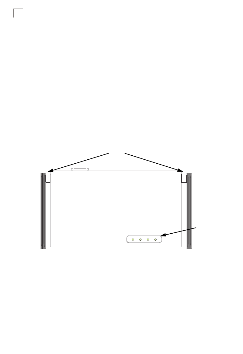
Hardware Description
Top P a nel
Antennas
PWR Link 11a 11g
LED
Indicators
1-2
Page 29
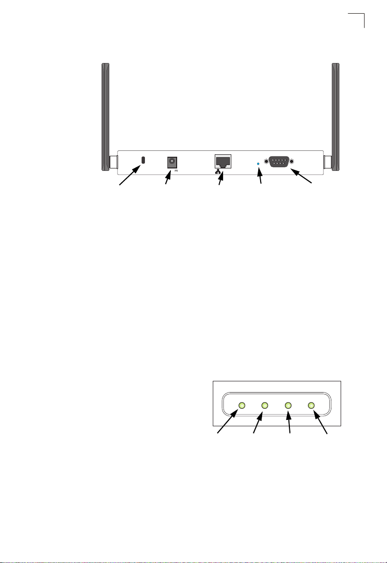
Rear Panel
Lock ConsolePOE In ResetDC 5V
Hardware Description
1
Security Slot
5 VDC
Power Socket
RJ-45 Port,
PoE Connector
Reset
Button
Console
Port
Component Description
Antennas
The access point includes integrated diversity antennas for wireless
communications. A diversity antenna system uses two identical antennas to receive
and transmit signals, helping to avoid multipath fading effects. When receiving, the
access point checks both antennas and selects the one with the strongest signal.
When transmitting, it will continue to use the antenna previously selected for
receiving. The access point never transmits from both antennas at the same time.
The antennas transmit the outgoing signal as a toroidal sphere (doughnut shaped),
with the coverage extending most in a direction perpendicular to the antenna. The
antenna should be adjusted to an angle that provides the appropriate coverage for
the service area. For further information, see “Positioning the Antennas” on 2-2.
LED Indicators
The access point includes four status LED
indicators, as described in the following
figure and table.
PWR Link 11a 11g
Power
Ethernet
Link/Activity
802.11a
Wireless
Link/Activity
802.11b/g
Wireless
Link/Activity
1-3
Page 30

Introduction
1
LED Status Description
PWR On Indicates that the system is working normally.
Flashing Indicates running a self-test or loading the software program.
Flashing (Prolonged) Indicates system errors.
Link On Indicates a valid 10/100 Mbps Ethernet cable link.
Flashing Indicates that the access point is transmitting or receiving data
11a On Indicates that the 802.11a radio is enabled.
Flashing Indicates that the access point is transmitting or receiving data
Off Indicates that the 802.11a radio is disabled.
11g On Indicates that the 802.11b/g radio is enabled.
Flashing Indicates that the access point is transmitting or receiving data
Off Indicates that the 802.11b/g radio is disabled.
on a 10/100 Mbps Ethernet LAN. Flashing rate is proportional
to network activity.
through wireless links. Flashing rate is proportional to network
activity.
through wireless links. Flashing rate is proportional to network
activity.
Security Slot
The access point includes a Kensington security slot on the rear panel. You can
prevent unauthorized removal of the access point by wrapping the Kensington
security cable (not provided) around an unmovable object, inserting the lock into the
slot, and turning the key.
Console Port
This port is used to connect a console device to the access point through a serial
cable. This connection is described under “Console Port Pin Assignments” on page
B-3. The console device can be a PC or workstation running a VT-100 terminal
emulator, or a VT-100 terminal.
Ethernet Port
The access point has one 10BASE-T/100BASE-TX RJ-45 port that can be attached
directly to 10BASE-T/100BASE-TX LAN segments. These segments must conform
to the IEEE 802.3 or 802.3u specifications.
This port supports automatic MDI/MDI-X operation, so you can use straight-through
cables for all network connections to PCs, switches, or hubs.
The access point appears as an Ethernet node and performs a bridging function by
moving packets from the wired LAN to remote workstations on the wireless
infrastructure.
1-4
Page 31

Features and Benefits
Note: The RJ-45 port also supports Power over Ethernet (PoE) based on the IEEE
802.3af standard. Refer to the description for the “Power Connector” for
information on supplying power to the access point’s network port from a network
device, such as a switch, that provides Power over Ethernet (PoE).
Reset Button
This button is used to reset the access point or restore the factory default
configuration. If you hold down the button for less than 5 seconds, the access point
will perform a hardware reset. If you hold down the button for 5 seconds or more,
any configuration changes you may have made are removed, and the factory default
configuration is restored to the access point.
Power Connector
The access point does not have a power switch. It is powered on when connected to
the AC power adapter, and the power adapter is connected to a power source. The
power adapter automatically adjusts to any voltage between 100-240 volts at 50 or
60 Hz. No voltage range settings are required.
The access point may also receive Power over Ethernet (PoE) from a switch or
other network device that supplies power over the network cable based on the IEEE
802.3af standard.
Note that if the access point is connected to a PoE source device and also
connected to a local power source through the AC power adapter, AC power will be
disabled.
1
Features and Benefits
• Local network connection via 10/100 Mbps Ethernet ports or 54 Mbps wireless
interface (supporting up to 128 mobile users)
• IEEE 802.11a, 802.11b, and 802.11g compliant
• Interoperable with multiple vendors based on the IEEE 802.11f protocol
• Advanced security through 64/128/152-bit Wired Equivalent Protection (WEP)
encryption, IEEE 802.1X authentication via a RADIUS server, Wi-Fi Protected
Access (WPA), and MAC address filtering features to protect your sensitive data
and authenticate only authorized users to your network
• Provides seamless roaming within the IEEE 802.11a, 802.11b and 802.11g WLAN
environment
• Scans all available channels and selects the best channel for each client based on
the signal-to-noise ratio
• Allows the country of operation to be set to match regulatory requirements (for
countries outside of the United States)
1-5
Page 32

Introduction
1
System Defaults
The following table lists some of the access point’s basic system defaults. To reset
the access point defaults, use the CLI command “reset configuration” from the Exec
level prompt.
Table 1-1. System Defaults
Feature Parameter Default
Identification System Name SMC
Administration User Name admin
Password smcadmin
General HTTP Server Enabled
HTTP Server Port 80
HTTP Server Enabled
HTTP Server Port 443
TCP/IP DHCP Enabled
IP Address 192.168.2.2
Subnet Mask 255.255.255.0
Default Gateway 0.0.0.0
Primary DNS IP 0.0.0.0
Secondary DNS IP 0.0.0.0
RADIUS (Primary and
Secondary)
SSH Server Status Enabled
PPPoE PPPoE Status Disabled
IP Address 0.0.0.0
Port 1812
Key DEFAULT
Timeout 5 seconds
Retransmit attempts 3
Accounting Port 0 (Disabled)
Interim Update Timeout 3600 seconds
Server Port 22
1-6
Page 33

Table 1-1. System Defaults
Feature Parameter Default
MAC Authentication MAC Disabled
Authentication Session Timeout 0 minutes (disabled)
Local MAC System Default Allowed
Local MAC Permission Allowed
802.1X Authentication Status Disabled
Broadcast Key Refresh 0 minutes (disabled)
Session Key Refresh 0 minutes (disabled)
Reauthentication Refresh Rate 0 seconds (disabled)
Supplicant Disabled
VLAN Management VLAN ID 1
VLAN ID (VAP Interface) 1
VLAN Tag Support Disabled
QoS QoS Mode Off
SVP (SpectraLink Voice Priority) Disabled
Filter Control Local Bridge Disabled
AP Management Enabled
Ethernet Type Disabled
SNMP Status Enabled
Location null
Contact null
Community (Read Only) Public
Community
(Read/Write)
Traps Enabled
Trap Destination (1-4) Disabled
Trap Destination IP Address null
Trap Destination Community
Name
SNMP v3 Groups RO
SNMP v3 Users none
Private
Public
RWAuth
RWPriv
System Defaults
1
1-7
Page 34

Introduction
1
Table 1-1. System Defaults
Feature Parameter Default
System Logging Syslog Disabled
Logging Host Disabled
Logging Console Disabled
IP Address / Host Name 0.0.0.0
Logging Level Informational
Logging Facility Type 16
System Clock SNTP Server Status Enabled
SNTP Server 1 IP 137.92.140.80
SNTP Server 2 IP 192.43.244.18
Date and Time 00:00, Jan 1, 1970 (when there is no time
Daylight Saving Time Disabled
Time Zone GMT-5 (Eastern Time, US and Canada)
Ethernet Interface Speed and Duplex Auto
server)
1-8
Page 35

Table 1-1. System Defaults
Feature Parameter Default
Wireless Interface
802.11a
Wireless Security
802.11a
IAPP Enabled
SSID SMC
Turbo Mode Disabled
Status Disabled
Auto Channel Select Enabled
Closed System Disabled
Transmit Power Full
Max Station Data Rate 54 Mbps
Multicast Data Rate 6 Mbps
Beacon Interval 100 TUs
Data Beacon Rate (DTIM Interval) 1 beacon
RTS Threshold 2347 bytes
Association Timeout Interval 30 minutes
Authentication Timeout Interval 60 minutes
Rogue AP Detection Disabled
Antenna Control Method Diversity
Antenna ID 0x0000
Antenna Location Indoor
Authentication Type Open System
Data Encryption Disabled
WEP Key Length 128 bits
WEP Key Type Hexadecimal
WEP Transmit Key Number 1
WEP Keys null
WPA Configuration Mode WEP Only (Disabled)
WPA Key Management WPA Pre-shared Key
WPA PSK Type Alphanumeric
Multicast Cipher WEP
System Defaults
1
1-9
Page 36

Introduction
1
Table 1-1. System Defaults
Feature Parameter Default
Wireless Interface
802.11b/g
Wireless Security
802.11b/g
IAPP Enabled
SSID SMC
Radio Mode b+g
Status Disabled
Auto Channel Select Enabled
Closed System Disabled
Transmit Power Full
Max Station Data Rate 54 Mbps
Multicast Data Rate 5.5 Mbps
Preamble Length Long
Beacon Interval 100 TUs
Data Beacon Rate (DTIM Interval) 1 beacon
RTS Threshold 2347 bytes
Association Timeout Interval 30 minutes
Authentication Timeout Interval 60 minutes
Rogue AP Detection Disabled
Antenna Control Method Diversity
Antenna ID 0x0000
Antenna Location Indoor
Authentication Type Open System
Data Encryption Disabled
WEP Key Length 128 bits
WEP Key Type Hexadecimal
WEP Transmit Key Number 1
WEP Keys null
WPA Configuration Mode WEP Only (Disabled)
WPA Key Management WPA Pre-shared Key
WPA PSK Type Alphanumeric
Multicast Cipher WEP
1-10
Page 37

Table 1-1. System Defaults
Feature Parameter Default
Link Integrity Status Disabled
Ping Interval 30 seconds
Fail Retry Count 6
System Defaults
1
1-11
Page 38

1
Introduction
1-12
Page 39

Chapter 2: Hardware Installation
1. Select a Site – Choose a proper place for the access point. In general, the best
location is at the center of your wireless coverage area, within line of sight of all
wireless devices. Try to place the access point in a position that can best cover
its Basic Service Set (refer to “Infrastructure Wireless LAN” on page 4-3). For
optimum performance, consider these points:
• Mount the access point as high as possible above any obstructions in the
coverage area.
• Avoid mounting next to or near building support columns or other obstructions
that may cause reduced signal or null zones in parts of the coverage area.
• Mount away from any signal absorbing or reflecting structures (such as those
containing metal).
2. Mount the Access Point – The access point can be mounted on any
horizontal surface.
Mounting on a horizontal surface – To keep the access point from sliding on the
surface, attach the four rubber feet provided in the accessory kit to the marked
circles on the bottom of the access point.
Lock the Access Point in Place – To prevent unauthorized removal of the
access point, you can use a Kensington Slim MicroSaver security cable (not
included) to attach the access point to a fixed object.
3. Connect the Power Cord – Connect the power adapter to the access point,
and the power cord to an AC power outlet.
Otherwise, the access point can derive its operating power directly from the
RJ-45 port when connected to a device that provides IEEE 802.3af compliant
Power over Ethernet (PoE).
Note: If the access point is connected to both a PoE source device and an AC power
source, AC power will be disabled.
Caution: Use ONLY the power adapter supplied with this access point. Otherwise, the
product may be damaged.
2-1
Page 40

Hardware Installation
2
4. Observe the Self Test – When you power on the access point, verify that the
PWR indicator stops flashing and remains on, and that the other indicators start
functioning as described under “LED Indicators” on page 1-3. If the PWR LED
does not stop flashing, the self test has not completed correctly. Refer to
“Troubleshooting” on page A-1.
5. Connect the Ethernet Cable – The access point can be wired to a 10/100
Mbps Ethernet through a network device such as a hub or a switch. Connect
your network to the RJ-45 port on the back panel with category 3, 4, or 5 UTP
Ethernet cable. When the access point and the connected device are powered
on, the Ethernet Link LED should light indicating a valid network connection. If
this LED fails to turn on refer to “Troubleshooting” on page A-1.
Note: The RJ-45 port on the access point supports auto=MDI/MDI-X operation, so you
can use either straight-through or crossover cable to connect to switches or PCs.
6. Position the Antennas – Each antenna emits a radiation pattern that is
toroidal (doughnut shaped), with the coverage extending most in the direction
perpendicular to the antenna. Therefore, the antennas should be oriented so
that the radio coverage pattern fills the intended horizontal space. Also, the
diversity antennas should both be positioned along the same axes, providing
the same coverage area. For example, if the access point is mounted on a
horizontal surface, both antennas should be positioned pointing vertically up to
provide optimum coverage.
7. Connect the Console Port – Connect the console cable (included) to the
RS-232 console port for accessing the command-line interface. You can
manage the access point using the console port (Chapter 6), the web interface
(Chapter 5), or SNMP management software such as SMC’s EliteView.
2-2
Page 41

Chapter 3: External Antennas
The SMC2555W-AG2 provides a variety of external antenna options for extending
the radio range and shaping the coverge area. These antennas offer a number of
different mounting locations, including indoor or outdoor, wall, ceiling, or radio mast.
This chapter shows you how to install an external antenna for your
SMC2555W-AG2.
Note: The use of external antennas with the access point requires professional
personnel that are trained in the installation of radio transmitting equipment. The
user is responsible for compliance with local regulations concerning items such as
antenna gain, cables, lightning arrestors, and transmit power. Therefore, you must
consult a professional contractor knowledgeable in local radio regulations prior to
equipment installation.
Installation Procedures
Follow these steps to install an external antenna and connect it to the
SMC2555W-AG2.
Caution: Never mount the access point outdoors to be near an external antenna. The
1. Plan the Installation
access point must always be installed indoors.
• Pigtail Cables - Use the coax pigtail cable attached to the antenna to connect
to the access point. Because most pigtail cables are a relatively short length
(83 cm or 33 inches), be sure to find a suitable mounting position for the
antenna that is not too far from the access point. If an extension cable is
required, please contact a professional installer who is trained in RF
installation and knowledgeable in the local regulations.
• Installation Location - Plan the antenna’s position and orientation.
Warning: The radiated output power of this device is below the FCC radio
exposure limits. Nevertheless, the device should be used in such a
manner that the potential for human contact during normal operation
is minimized. To avoid the possibility of exceeding the FCC radio
frequency exposure limits, human proximity to the antennas should
not be less than 20 cm (8 inches) during normal operation.
Consider these points:
• Use the antenna’s mounting bracket or other hardware, if included.
• For optimum performance, mount antennas as high as possible above any
obstructions, and away from any signal absorbing or reflecting structures
(such as those containing metal)
• Be sure there are no other radio antennas mounted within 2 m (6 ft).
3-1
Page 42

External Antennas
3
• Consider the antenna’s radio coverage pattern so that it can properly cover
the intended service area.
• Omnidirectional Antennas - Consider these factors when selecting a
location for these antennas:
• Always mount the antenna in a vertical orientation so that the radio
coverage pattern fills the intended horizontal space.
• For optimum coverage, mount the antenna at the center of the area with a
line-of-sight path to all points within the area.
• Avoid mounting next to or near building support columns or other
obstructions that may cause reduced signal or null zones in parts of the
coverage area.
• When mounting outdoors using a mast, make sure that the antenna extends
beyond the top of the mast.
• Directional Antennas - Consider these factors when selecting a location for
these antennas:
• For optimum coverage, mount the antenna above any obstructions,
directed at the center of the coverage area sector.
• High-gain directional antennas provide a flattened radio coverage pattern
in the horizontal plane. Use the tilting or articulated mounts to point the
antennas towards the coverage area.
• Outdoor Installation - When installing an antenna outdoors, be sure to
consider these additional factors:
• Always place the antenna away from power and telephone lines
• Make sure that the antenna, any supporting structure, and cables are all
properly grounded.
• For lightning protection, consider using a lightning arrestor immediately
before the cable enters the building.
Warning: Never install an antenna or construct a radio mast near overhead
power lines.
2. Mount the Antenna
Install the antenna in its planned location using the brackets, clips, or other hardware
included in the antenna package.
Refer to documentation included with the antenna for specific information and
installation instructions.
3. Connect Pigtail Cables to the Access Point
Use the pigtail cables that are attached to the antenna, or are included in the
antenna package. If an extension cable is required, please contact a professional
installer who is trained in RF installation and knowledgeable in the local regulations.
Note that diversity antennas have two pigtail cables. A diversity antenna includes
two internal antenna elements that are identical. Both antenna pigtail cables must be
connected to the access point for correct operation.
3-2
Page 43

Installation Procedures
Other non-diversity antennas, can be connected to either antenna connector and
then configured for usage using the antenna options in the user interface.
To connect pigtail cables to the access point, follow these steps:
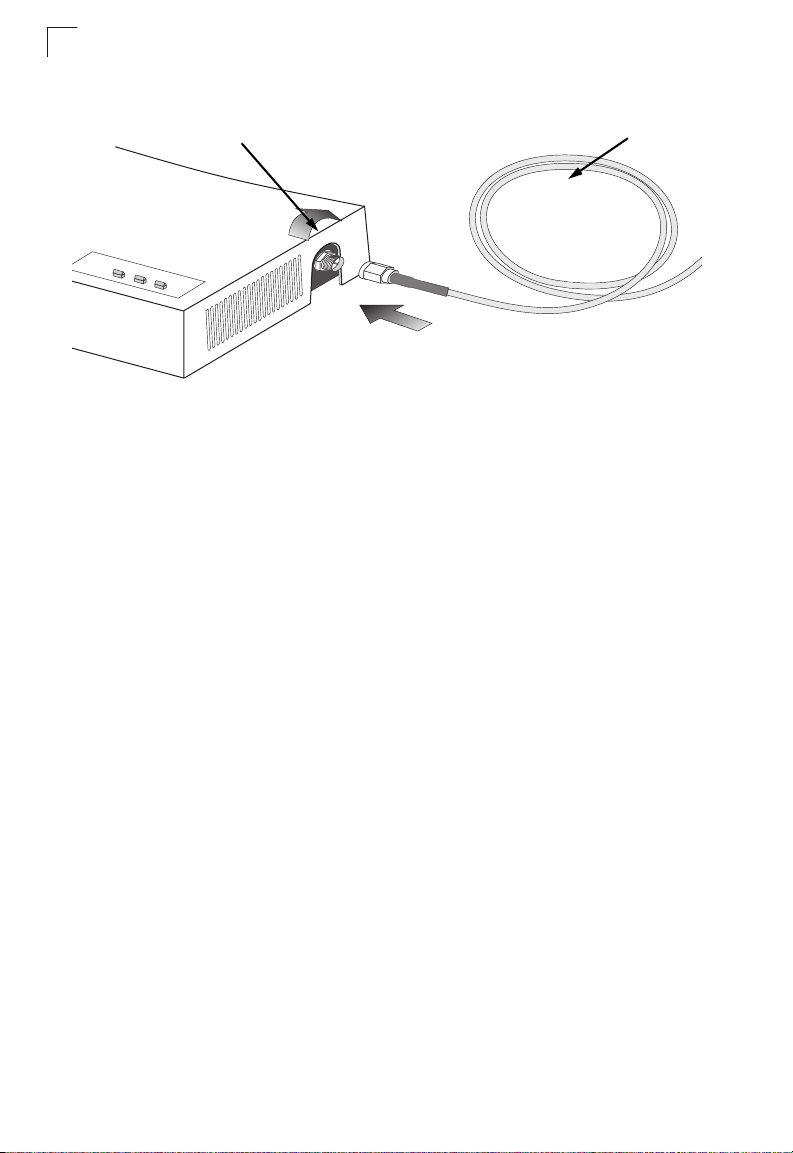
1. Disable the access point radio using the web browser interface, CLI, or SNMP.
2. Remove power to the access point.
3. Remove both of the access point’s antennas by unscrewing them at their base.
Unscrew antenna
to remove
3
4. For diversity antennas, connect the antenna pigtail cables to the exposed
Reverse SMA connectors on both sides of the access point.
For non-diversity antennas, be sure to connect the single pigtail cable to the
Reverse SMA connector on the access point’s side activated through the
software interface.
3-3
Page 44
3
External Antennas
Screw onto access point’s
5. Reconnect power to the access point.
Note: Before enabling the radio with an external antenna attached, be sure to first
configure the access point’s antenna mode.
Antenna pigtail cable
3-4
Page 45

Chapter 4: Network Configuration
Wireless networks support a stand-alone configuration as well as an integrated
configuration with 10/100 Mbps Ethernet LANs. The 2.4 GHz/5 GHz Wireless
Access Point also provides repeater and bridging services that can be configured
independently on either the 5 GHz or 2.4 GHz radio interfaces.
Access points can be deployed to support wireless clients and connect wired LANs
in the following configurations:
• Ad hoc for departmental, SOHO or enterprise LANs
• Infrastructure for wireless LANs
• Infrastructure wireless LAN for roaming wireless PCs
• Infrastructure wireless bridge to connect wired LANs
• Infrastructure wireless repeater for extended range
The 802.11b and 802.11g frequency band which operates at 2.4 GHz can easily
encounter interference from other 2.4 GHz devices, such as other 802.11b or g
wireless devices, cordless phones and microwave ovens. If you experience poor
wireless LAN performance, try the following measures:
• Limit any possible sources of radio interference within the service area
• Increase the distance between neighboring access points
• Decrease the signal strength of neighboring access points
• Increase the channel separation of neighboring access points (e.g. up to 5
channels of separation for 802.11b and 802.11g)
4-1
Page 46

Network Configuration
4
Network Topologies
Ad Hoc Wireless LAN (no Access Point)
An ad hoc wireless LAN consists of a group of computers, each equipped with a
wireless adapter, connected via radio signals as an independent wireless LAN.
Computers in a specific ad hoc wireless LAN must therefore be configured to the
same radio channel. An ad hoc wireless LAN can be used for a branch office or
SOHO operation.
Ad Hoc Wireless LAN
Notebook with
Wireless USB Adapter
Notebook with
Wireless PC Card
PC with Wireless
PCI Adapter
4-2
Page 47

Network Topologies
Infrastructure Wireless LAN
The access point also provides access to a wired LAN for wireless workstations. An
integrated wired/wireless LAN is called an Infrastructure configuration. A Basic
Service Set (BSS) consists of a group of wireless PC users, and an access point
that is directly connected to the wired LAN. Each wireless PC in this BSS can talk to
any computer in its wireless group via a radio link, or access other computers or
network resources in the wired LAN infrastructure via the access point.
The infrastructure configuration not only extends the accessibility of wireless PCs to
the wired LAN, but also increases the effective wireless transmission range for
wireless PCs by passing their signal through one or more access points.
A wireless infrastructure can be used for access to a central database, or for
connection between mobile workers, as shown in the following figure.
Wired LAN Extension
to Wireless Clients
Server
4
Desktop PC
Switch
Access Point
Notebook PC
Desktop PC
4-3
Page 48

Network Configuration
4
Infrastructure Wireless LAN for Roaming Wireless PCs
The Basic Service Set (BSS) defines the communications domain for each access
point and its associated wireless clients. The BSS ID is a 48-bit binary number
based on the access point’s wireless MAC address, and is set automatically and
transparently as clients associate with the access point. The BSS ID is used in
frames sent between the access point and its clients to identify traffic in the service
area.
The BSS ID is only set by the access point, never by its clients. The clients only
need to set the Service Set Identifier (SSID) that identifies the service set provided
by one or more access points. The SSID can be manually configured by the clients,
can be detected in an access point’s beacon, or can be obtained by querying for the
identity of the nearest access point. For clients that do not need to roam, set the
SSID for the wireless card to that used by the access point to which you want to
connect.
A wireless infrastructure can also support roaming for mobile workers. More than
one access point can be configured to create an Extended Service Set (ESS). By
placing the access points so that a continuous coverage area is created, wireless
users within this ESS can roam freely. All wireless network cards and adapters and
wireless access points within a specific ESS must be configured with the same
SSID.
Seamless Roaming
Between Access Points
4-4
Desktop PC
Switch
Access Point
Desktop PC
Server
Notebook PC
<BSS 1>
Switch
Access Point
Notebook PC
<BSS 2>
<ESS>
Page 49

Network Topologies
Infrastructure Wireless Bridge
The IEEE 802.11 standard defines a WIreless Distribution System (WDS) for bridge
connections between BSS areas (access points). The access point uses WDS to
forward traffic on links between units.
The access point supports WDS bridge links on either the 5 GHz (802.11a) or
2.4 GHz (802.11b/g) bands and can be used with various external antennas to offer
flexible deployment options.
Up to six WDS bridge links can be specified for each unit in the wireless bridge
network. One unit only must be configured as the “root bridge” in the wireless
network. The root bridge should be the unit connected to the main core of the wired
LAN. Other bridges must configure one “parent” link to the root bridge or to a bridge
connected to the root bridge. The other five available WDS links can be specified as
“child” links to other bridges. This forms a tiered-star topology for the wireless bridge
network.
When using WDS on a radio band, only wireless bridge units can associate to each
other. Wireless clients can only associate with the access point using a radio band
set to access point or repeater mode.
4
802.11g Radio
AP Link
802.11g Radio
AP Link
Network
Core
802.11a Radio
Bridge Link
Bridge
Root Bridge
Wireless Bridge Links
Between Access Points
802.11a Radio
Bridge Link
802.11g Radio
802.11g Radio
AP Link
802.11a Radio
Bridge Link
AP Link
Bridge
Bridge
4-5
Page 50

Network Configuration
4
Infrastructure Wireless Repeater
The access point can also operate in a bridge “repeater” mode to extend the range
of links to wireless clients. The access point uses WDS to forward traffic between
the repeater bridge and the root bridge. The access point supports up to six WDS
repeater links.
In repeater mode, the access point does not support an Ethernet link to a wired LAN.
Note that when the access point operates in this mode only half the normal
throughput is possible. This is because the access point has to receive and then
re-transmit all data on the same channel.
Network
Core
Wireless Repeater Links
Between Access Points
Root Bridge
802.11g Radio
802.11g Radio
Repeater Link
Repeater Link
4-6
802.11g Radio
AP Link
Repeater
802.11g Radio
AP Link
Repeater
Page 51

Chapter 5: Initial Configuration
The 2.4 GHz/5 GHz Wireless Access Point offers a variety of management options,
including a web-based interface, a direct connection to the console port, Telnet,
Secure Shell (SSH), or using SNMP software.
The initial configuration steps can be made through the web browser interface or
CLI. The access point requests an IP address via DHCP by default. If no response is
received from the DHCP server, then the access point uses the default address
192.168.2.2. If this address is not compatible with your network, you can first use the
command line interface (CLI) as described below to configure a valid address.
Note: Units sold in countries outside the United States are not configured with a specific
country code. You must use the CLI to set the country code and enable wireless
operation (page 5-3).
Initial Setup through the CLI
Required Connections
The access point provides an RS-232 serial port that enables a connection to a PC
or terminal for monitoring and configuration. Attach a VT100-compatible terminal, or
a PC running a terminal emulation program to the access point. You can use the
console cable provided with this package, or use a cable that complies with the
wiring assignments shown on page B-3.
To connect to the console port, complete the following steps:
1. Connect the console cable to the serial port on a terminal, or a PC running
terminal emulation software, and tighten the captive retaining screws on the
DB-9 connector.
2. Connect the other end of the cable to the RS-232 serial port on the access
point.
3. Make sure the terminal emulation software is set as follows:
• Select the appropriate serial port (COM port 1 or 2).
• Set the data rate to 9600 baud.
• Set the data format to 8 data bits, 1 stop bit, and no parity.
• Set flow control to none.
• Set the emulation mode to VT100.
• When using HyperTerminal, select Terminal keys, not Windows keys.
5-1
Page 52

Initial Configuration
5
Note: When using HyperTerminal with Microsoft® Windows® 2000, make sure that you
have Windows 2000 Service Pack 2 or later installed. Windows 2000 Service
Pack 2 fixes the problem of arrow keys not functioning in HyperTerminal’s VT100
emulation. See www.microsoft.com for information on Windows 2000 service
packs.
4. Once you have set up the terminal correctly, press the [Enter] key to initiate the
console connection. The console login screen will be displayed.
For a description of how to use the CLI, see “Using the Command Line Interface” on
page 7-1. For a list of all the CLI commands and detailed information on using the
CLI, refer to “Command Groups” on page 7-6.
Initial Configuration Steps
Logging In – Enter “admin” for the user name. The default password is “smcadmin.”
The CLI prompt appears displaying the access point’s name.
Username: admin
Password:
Enterprise AP#
Setting the IP Address – By default, the access point is configured to obtain IP
address settings from a DHCP server. If a DHCP server is not available, the IP
address defaults to 192.168.2.2, which may not be compatible with your network.
You will therefore have to use the command line interface (CLI) to assign an IP
address that is compatible with your network.
Type “configure” to enter configuration mode, then type “interface ethernet” to
access the Ethernet interface-configuration mode.
Enterprise AP#configure
Enterprise AP(config)#interface ethernet
Enterprise AP(config-if)#
First type “no ip dhcp” to disable DHCP client mode. Then type “ip address
ip-address netmask gateway,” where “ip-address” is the access point’s IP address,
“netmask” is the network mask for the network, and “gateway” is the default gateway
router. Check with your system administrator to obtain an IP address that is
compatible with your network.
Enterprise AP(if-ethernet)#no ip dhcp
Enterprise AP(if-ethernet)#ip address 192.168.2.2
255.255.255.0 192.168.2.254
Enterprise AP(if-ethernet)#
5-2
Page 53

Logging In
After configuring the access point’s IP parameters, you can access the management
interface from anywhere within the attached network. The command line interface
can also be accessed using Telnet from any computer attached to the network.
Setting the Country Code – Units sold in the United States are configured by
default to use only radio channels 1-11 in 802.11b or 802.11g mode as defined by
FCC regulations. Units sold in other countries are configured by default without a
country code (i.e., 99). You must use the CLI to set the country code. Setting the
country code restricts operation of the access point to the radio channels and
transmit power levels permitted for wireless networks in the specified country.
Type “exit” to leave configuration mode. Then type “country ?” to display the list of
countries. Select the code for your country, and enter the country command again,
following by your country code (e.g., tw for Taiwan).
Enterprise AP#country tw
Enterprise AP#
Note: Command examples shown later in this manual abbreviate the console prompt to
“AP” for simplicity.
Logging In
There are only a few basic steps you need to complete to connect the access point
to your corporate network, and provide network access to wireless clients.
5
The access point can be managed by any computer using a web browser (Internet
Explorer 5.0 or above, or Netscape Navigator 6.2 or above). Enter the default IP
address: http://192.168.2.2
Logging In – Enter the username “admin,” and password “smcadmin” then click
LOGIN. For information on configuring a user name and password, see page 6-29.
5-3
Page 54

Initial Configuration
5
The home page displays the Main Menu.
5-4
Page 55

Chapter 6: System Configuration
Before continuing with advanced configuration, first complete the initial configuration
steps described in Chapter 4 to set up an IP address for the access point.
The access point can be managed by any computer using a web browser (Internet
Explorer 5.0 or above, or Netscape Navigator 6.2 or above). Enter the configured IP
address of the access point, or use the default address: http://192.168.2.2
To log into the access point, enter the default user name “admin” and the password
“smcadmin”, then press “LOGIN”. When the home page displays, click on Advanced
Setup. The following page will display.
The information in this chapter is organized to reflect the structure of the web
screens for easy reference. However, it is recommended that you configure a user
name and password as the first step under advanced configuration to control
management access to this device (page 6-29).
6-1
Page 56

System Configuration
6
Advanced Configuration
The Advanced Configuration pages include the following options.
Table 6-2. Menu
Menu Description Page
System Configures basic administrative and client access 6-3
Identification Specifies the host name 6-3
TCP / IP Settings Configures the IP address, subnet mask, gateway, and domain
RADIUS Configures the RADIUS server for wireless client authentication
SSH Settings Configures Secure Shell management access 6-11
Authentication Configures 802.1X client authentication, with an option for MAC
Filter Control Filters communications between wireless clients, access to the
VLAN Enables VLAN support and sets the management VLAN ID 6-20
WDS Settings Configures bridge or repeater modes for each radio interface and
AP Management Configures access to management interfaces 6-28
Administration Configures user name and password for management
System Log Controls logging of error messages; sets the system clock via
SNMP Configures SNMP settings 6-38
SNMP Controls access to this access point from management stations
SNMP Trap Filters Defines trap filters for SNMPv3 users 6-46
SNMP Targets Specifies SNMPv3 users that will receive trap messages 6-48
Radio Interface A Configures the IEEE 802.11a interface 6-50
Radio Settings Configures common radio signal parameters and other settings for
Security Enables each virtual access point (VAP) interface, sets the Service
Radio Interface G Configures the IEEE 802.11g interface 6-50
Radio Settings Configures common radio signal parameters and other settings for
name servers
and accounting
address authentication
management interface from wireless clients, and traffic matching
specific Ethernet protocol types
sets spanning tree parameters
upgrades software from local file, FTP or TFTP server;
configuration settings to factory defaults; and resets the access
point
SNTP server or manual configuration
using SNMP, as well as the hosts that will receive trap messages
each VAP interface
Set Identifier (SSID), and configures wireless security
each VAP interface
access;
resets
6-5
6-7
6-12
6-17
6-22
6-29
6-34
6-38
6-51
6-69
6-66
6-2
Page 57

Advanced Configuration
Table 6-2. Menu
Menu Description Page
Security Enables each VAP interface, sets the SSID, and configures
Status Displays information about the access point and wireless clients 6-86
AP Status Displays configuration settings for the basic system and the
Station Station Shows the wireless clients currently associated with the access
Event Logs Shows log messages stored in memory 6-92
wireless security
wireless interface
point
6-69
6-86
6-89
System Identification
The system name for the access point can be left at its default setting. However,
modifying this parameter can help you to more easily distinguish different devices in
your network.
6
System Name – An alias for the access point, enabling the device to be uniquely
identified on the network. (Default: SMC; Range: 1-32 characters)
6-3
Page 58

System Configuration
6
CLI Commands for System Identification – Enter the global configuration mode, and
use the system name command to specify a new system name. Then return to the
Exec mode, and use the show system command to display the changes to the
system identification settings.
Enterprise AP#config
Enterprise AP(config)#system name R&D
Enterprise AP(config)#end 7-87
Enterprise AP#show system 7-22
Enterprise AP#config 7-8
Enter configuration commands, one per line.
Enterprise AP(config)#system name R&D
Enterprise AP(config)#end 7-87
Enterprise AP#show system 7-22
System Information
==============================================================
Serial Number :
System Up time : 0 days, 0 hours, 32 minutes, 22 seconds
System Name : R&D
System Location :
System Contact : Contact
System Country Code : US - UNITED STATES
MAC Address : 00-12-CF-12-34-60
Radio A MAC Address : 00-12-CF-12-34-61
Radio G MAC Address : 00-12-CF-12-34-65
IP Address : 192.168.1.1
Subnet Mask : 255.255.255.0
Default Gateway : 0.0.0.0
VLAN State : DISABLED
Management VLAN ID(AP): 1
IAPP State : ENABLED
DHCP Client : ENABLED
HTTP Server : ENABLED
HTTP Server Port : 80
HTTPS Server : ENABLED
HTTPS Server Port : 443
Slot Status : Dual band(a/g)
Boot Rom Version : v1.1.5
Software Version : v4.3.2.0b01
SSH Server : ENABLED
SSH Server Port : 22
Telnet Server : ENABLED
DHCP Relay : DISABLED
==============================================================
Enterprise AP#
7-14
7-14
6-4
Page 59

Advanced Configuration
TCP / IP Settings
Configuring the access point with an IP address expands your ability to manage the
access point. A number of access point features depend on IP addressing to
operate.
Note: You can use the web browser interface to access IP addressing only if the access
point already has an IP address that is reachable through your network.
By default, the access point will be automatically configured with IP settings from a
Dynamic Host Configuration Protocol (DHCP) server. However, if you are not using
a DHCP server to configure IP addressing, use the CLI to manually configure the
initial IP values (see page 5-2). After you have network access to the access point,
you can use the web browser interface to modify the initial IP configuration, if
needed.
Note: If there is no DHCP server on your network, or DHCP fails, the access point will
automatically start up with a default IP address of 192.168.2.2.
6
DHCP Client (Enable) – Select this option to obtain the IP settings for the access
point from a DHCP (Dynamic Host Configuration Protocol) server. The IP address,
subnet mask, default gateway, and Domain Name Server (DNS) address are
dynamically assigned to the access point by the network DHCP server.
(Default: Enabled)
DHCP Client (Disable) – Select this option to manually configure a static address for
the access point.
• IP Address: The IP address of the access point. Valid IP addresses consist of four
decimal numbers, 0 to 255, separated by periods.
6-5
Page 60

System Configuration
6
• Subnet Mask: The mask that identifies the host address bits used for routing to
specific subnets.
• Default Gateway: The default gateway is the IP address of the router for the access
point, which is used if the requested destination address is not on the local subnet.
If you have management stations, DNS, RADIUS, or other network servers
located on another subnet, type the IP address of the default gateway router in the
text field provided. Otherwise, leave the address as all zeros (0.0.0.0).
• Primary and Secondary DNS Address: The IP address of Domain Name Servers
on the network. A DNS maps numerical IP addresses to domain names and can
be used to identify network hosts by familiar names instead of the IP addresses.
If you have one or more DNS servers located on the local network, type the IP
addresses in the text fields provided. Otherwise, leave the addresses as all zeros
(0.0.0.0).
CLI Commands for TCP/IP Settings – From the global configuration mode, enter the
interface configuration mode with the interface ethernet command. Use the ip
dhcp command to enable the DHCP client, or no ip dhcp to disable it. To manually
configure an address, specify the new IP address, subnet mask, and default
gateway using the ip address command. To specify DNS server addresses use the
dns server command. Then use the show interface ethernet command from the
Exec mode to display the current IP settings.
Enterprise AP(config)#interface ethernet 7-87
Enter Ethernet configuration commands, one per line.
Enterprise AP(if-ethernet)#no ip dhcp
Enterprise AP(if-ethernet)#ip address 192.168.1.2
255.255.255.0 192.168.1.253
Enterprise AP(if-ethernet)#dns primary-server 192.168.1.55 7-88
Enterprise AP(if-ethernet)#dns secondary-server 10.1.0.55 7-88
Enterprise AP(config)#end 7-8
Enterprise AP#show interface ethernet 7-91
Ethernet Interface Information
========================================
IP Address : 192.168.1.2
Subnet Mask : 255.255.255.0
Default Gateway : 192.168.1.253
Primary DNS : 192.168.1.55
Secondary DNS : 10.1.0.55
Speed-duplex : 100Base-TX Full Duplex
Admin status : Up
Operational status : Up
========================================
Enterprise AP#
7-89
7-88
6-6
Page 61

Advanced Configuration
RADIUS
Remote Authentication Dial-in User Service (RADIUS) is an authentication protocol
that uses software running on a central server to control access to RADIUS-aware
devices on the network. An authentication server contains a database of user
credentials for each user that requires access to the network.
A primary RADIUS server must be specified for the access point to implement IEEE
802.1X network access control and Wi-Fi Protected Access (WPA) wireless security.
A secondary RADIUS server may also be specified as a backup should the primary
server fail or become inaccessible.
In addition, the configured RADIUS server can also act as a RADIUS Accounting
server and receive user-session accounting information from the access point.
RADIUS Accounting can be used to provide valuable information on user activity in
the network.
Note: This guide assumes that you have already configured RADIUS server(s) to
support the access point. Configuration of RADIUS server software is beyond the
scope of this guide, refer to the documentation provided with the RADIUS server
software.
6
6-7
Page 62

System Configuration
6
6-8
Page 63

Advanced Configuration
MAC Address Format – MAC addresses can be specified in one of four formats,
using no delimeter, with a single dash delimeter, with multiple dash delimeters, and
with multiple colon delimeters.
VLAN ID Format – A VLAN ID (a number between 1 and 4094) can be assigned to
each client after successful authentication using IEEE 802.1X and a central RADIUS
server. The user VLAN IDs must be configured on the RADIUS server for each user
authorized to access the network. VLAN IDs can be entered as hexadecimal
numbers or as ASCII strings.
Primary Radius Server Setup – Configure the following settings to use RADIUS
authentication on the access point.
• IP Address: Specifies the IP address or host name of the RADIUS server.
• Port: The UDP port number used by the RADIUS server for authentication
messages. (Range: 1024-65535; Default: 1812)
• Key: A shared text string used to encrypt messages between the access point and
the RADIUS server. Be sure that the same text string is specified on the RADIUS
server. Do not use blank spaces in the string. (Maximum length: 255 characters)
• Timeout: Number of seconds the access point waits for a reply from the RADIUS
server before resending a request. (Range: 1-60 seconds; Default: 5)
• Retransmit attempts: The number of times the access point tries to resend a
request to the RADIUS server before authentication fails. (Range: 1-30; Default: 3)
• Accounting Port: The RADIUS Accounting server UDP port used for accounting
messages. (Range: 0 or 1024-65535; Default: 0, disabled)
• Interim Update Timeout: The interval between transmitting accounting updates to
the RADIUS server. (Range: 60-86400; Default: 3600 seconds)
Note: For the Timeout and Retransmit attempts fields, accept the default values unless
you experience problems connecting to the RADIUS server over the network.
6
Secondary Radius Server Setup – Configure a secondary RADIUS server to provide
a backup in case the primary server fails. The access point uses the secondary
server if the primary server fails or becomes inaccessible. Once the access point
switches over to the secondary server, it periodically attempts to establish
communication again with primary server. If communication with the primary server
is re-established, the secondary server reverts to a backup role.
6-9
Page 64

System Configuration
6
CLI Commands for RADIUS – From the global configuration mode, use the
radius-server address command to specify the address of the primary or
secondary RADIUS servers. (The following example configures the settings for the
primary RADIUS server.) Configure the other parameters for the RADIUS server.
Then use the show show radius command from the Exec mode to display the
current settings for the primary and secondary RADIUS servers.
Enterprise AP(config)#radius-server address 192.168.1.25 7-58
Enterprise AP(config)#radius-server port 181 7-59
Enterprise AP(config)#radius-server key green 7-59
Enterprise AP(config)#radius-server timeout 10 7-60
Enterprise AP(config)#radius-server retransmit 5 7-60
Enterprise AP(config)#radius-server port-accounting 1813 7-61
Enterprise AP(config)#radius-server timeout-interim 500 7-61
Enterprise AP(config)#exit
Enterprise AP#show radius
Radius Server Information
========================================
IP : 192.168.1.25
Port : 181
Key : *****
Retransmit : 5
Timeout : 10
Radius MAC format : no-delimiter
Radius VLAN format : HEX
========================================
Radius Secondary Server Information
========================================
IP : 0.0.0.0
Port : 1812
Key : *****
Retransmit : 3
Timeout : 5
Radius MAC format : no-delimiter
Radius VLAN format : HEX
========================================
Enterprise AP#
7-63
6-10
Page 65

Advanced Configuration
SSH Settings
Telnet is a remote management tool that can be used to configure the access point
from anywhere in the network. However, Telnet is not secure from hostile attacks.
The Secure Shell (SSH) can act as a secure replacement for Telnet. The SSH
protocol uses generated public keys to encrypt all data transfers passing between
the access point and SSH-enabled management station clients and ensures that
data traveling over the network arrives unaltered. Clients can then securely use the
local user name and password for access authentication.
Note that SSH client software needs to be installed on the management station to
access the access point for management via the SSH protocol.
Notes: 1. The access point supports only SSH version 2.0.
2. After boot up, the SSH server needs about two minutes to generate host
encryption keys. The SSH server is disabled while the keys are being
generated.
6
SSH Settings
• Telnet Server Status: Enables or disables the Telnet server. (Default: Enabled)
• SSH Server Status: Enables or disables the SSH server. (Default: Enabled)
• SSH Server Port: Sets the UDP port for the SSH server. (Range: 1-65535;
Default: 22)
6-11
Page 66

System Configuration
6
CLI Commands for SSH – To enable the SSH server, use the ip ssh-server enable
command from the CLI Ethernet interface configuration mode. To set the SSH
server UDP port, use the ip ssh-server port command. To view the current settings,
use the show system command from the CLI Exec mode (not shown in the
following example).
Enterprise AP(if-ethernet)#no ip telnet-server 7-17
Enterprise AP(if-ethernet)#ip ssh-server enable 7-16
Enterprise AP(if-ethernet)#ip ssh-server port 1124 7-16
Enterprise AP(if-ethernet)#exit
Enterprise AP(if-ethernet)#configure
Authentication
Wireless clients can be authenticated for network access by checking their MAC
address against the local database configured on the access point, or by using a
database configured on a central RADIUS server. Alternatively, authentication can
be implemented using the IEEE 802.1X network access control protocol.
A client’s MAC address provides relatively weak user authentication, since MAC
addresses can be easily captured and used by another station to break into the
network. Using 802.1X provides more robust user authentication using user names
and passwords or digital certificates. You can configure the access point to use both
MAC address and 802.1X authentication, with client station MAC authentication
occurring prior to IEEE 802.1X authentication. However, it is better to choose one or
the other, as appropriate.
Take note of the following points before configuring MAC address or 802.1X
authentication:
• Use MAC address authentication for a small network with a limited number of
users. MAC addresses can be manually configured on the access point itself
without the need to set up a RADIUS server, but managing a large number of MAC
addresses across many access points is very cumbersome. A RADIUS server can
be used to centrally manage a larger database of user MAC addresses.
• Use IEEE 802.1X authentication for networks with a larger number of users and
where security is the most important issue. When using 802.1X authentication, a
RADIUS server is required in the wired network to centrally manage the credentials
of the wireless clients. It also provides a mechanism for enhanced network security
using dynamic encryption key rotation or W-Fi Protected Access (WPA).
Note: If you configure RADIUS MAC authentication together with 802.1X, RADIUS MAC
address authentication is performed prior to 802.1X authentication. If RADIUS
MAC authentication succeeds, then 802.1X authentication is performed. If
RADIUS MAC authentication fails, 802.1X authentication is not performed.
• The access point can also operate in a 802.1X supplicant mode. This enables the
access point itself to be authenticated with a RADIUS server using a configured
MD5 user name and password. This prevents rogue access points from gaining
access to the network.
6-12
Page 67

Advanced Configuration
6
MAC Authentication – You can configure a list of the MAC addresses for wireless
clients that are authorized to access the network. This provides a basic level of
authentication for wireless clients attempting to gain access to the network. A
database of authorized MAC addresses can be stored locally on the access point or
remotely on a central RADIUS server.
(Default: Disabled)
• Disabled: No checks are performed on an associating station’s MAC address.
• Local MAC: The MAC address of the associating station is compared against the
local database stored on the access point. Use the Local MAC Authentication
section of this web page to set up the local database, and configure all access
points in the wireless network service area with the same MAC address database.
• Radius MAC: The MAC address of the associating station is sent to a configured
RADIUS server for authentication. When using a RADIUS authentication server for
MAC address authentication, the server must first be configured in the Radius
window (see “RADIUS” on page 6-7). The database of MAC addresses and
filtering policy must be defined in the RADIUS server.
Note: MAC addresses on the RADIUS server can be entered in four different formats
(see “RADIUS” on page 6-7).
6-13
Page 68

System Configuration
6
802.1X Supplicant – The access point can also operate in a 802.1X supplicant
mode. This enables the access point itself to be authenticated with a RADIUS server
using a configured MD5 user name and password. This prevents rogue access
points from gaining access to the network.
Local MAC Authentication – Configures the local MAC authentication database. The
MAC database provides a mechanism to take certain actions based on a wireless
client’s MAC address. The MAC list can be configured to allow or deny network
access to specific clients.
• System Default: Specifies a default action for all unknown MAC addresses (that is,
those not listed in the local MAC database).
• Deny: Blocks access for all MAC addresses except those listed in the local
database as “Allow.”
• Allow: Permits access for all MAC addresses except those listed in the local
database as “Deny.”
• MAC Authentication Settings: Enters specified MAC addresses and permissions
into the local MAC database.
• MAC Address: Physical address of a client. Enter six pairs of hexadecimal digits
separated by hyphens; for example, 00-90-D1-12-AB-89.
• Permission: Select Allow to permit access or Deny to block access. If Delete is
selected, the specified MAC address entry is removed from the database.
• Update: Enters the specified MAC address and permission setting into the local
database.
• MAC Authentication Table: Displays current entries in the local MAC database.
6-14
Page 69

Advanced Configuration
CLI Commands for Local MAC Authentication – Use the mac-authentication
server command from the global configuration mode to enable local MAC
authentication. Use the mac-authentication session-timeout command to set the
authentication interval. Set the default action for MAC addresses not in the local
table using the address filter default command, then enter MAC addresses in the
local table using the address filter entry command. To remove an entry from the
table, use the address filter delete command. To display the current settings, use
the show authentication command from the Exec mode.
Enterprise AP(config)#mac-authentication server local 7-71
Enterprise AP(config)#mac-authentication session-timeout 5 7-71
Enterprise AP(config)#address filter default denied 7-69
Enterprise AP(config)#address filter entry
00-70-50-cc-99-1a denied
Enterprise AP(config)#address filter entry
00-70-50-cc-99-1b allowed
Enterprise AP(config)#address filter entry
00-70-50-cc-99-1c allowed
Enterprise AP(config)#address filter delete
00-70-50-cc-99-1c
Enterprise AP(config)#exit
Enterprise AP#show authentication
Authentication Information
===========================================================
MAC Authentication Server : LOCAL
MAC Auth Session Timeout Value : 0 min
802.1x supplicant : DISABLED
802.1x supplicant user : EMPTY
802.1x supplicant password : EMPTY
Address Filtering : DENIED
System Default : ALLOW addresses not found in filter table.
Filter Table
MAC Address Status
----------------- ---------00-70-50-cc-99-1a DENIED
00-70-50-cc-99-1b ALLOWED
=========================================================
Enterprise AP#
7-70
7-70
7-67
6
6-15
Page 70

System Configuration
6
CLI Commands for RADIUS MAC Authentication – Use the mac-authentication
server command from the global configuration mode to enable remote MAC
authentication. Set the timeout value for re-authentication using the macauthentication session-timeout command. Be sure to also configure connection
settings for the RADIUS server (not shown in the following example). To display the
current settings, use the show authentication command from the Exec mode.
Enterprise AP(config)#mac-authentication server remote 7-71
Enterprise AP(config)#mac-authentication
session-timeout 300
Enterprise AP(config)#exit
Enterprise AP#show authentication
Authentication Information
===========================================================
MAC Authentication Server : REMOTE
MAC Auth Session Timeout Value : 300 min
802.1x supplicant : DISABLED
802.1x supplicant user : EMPTY
802.1x supplicant password : EMPTY
Address Filtering : DENIED
System Default : DENY addresses not found in filter table.
Filter Table
MAC Address Status
----------------- ---------00-70-50-cc-99-1a DENIED
00-70-50-cc-99-1b ALLOWED
=========================================================
Enterprise AP#
7-71
7-67
CLI Command for 802.1x Supplicant – To configure the access point to operate as a
802.1X supplicant, first use the 802.1X supplicant user command to set a user
name and password for the access point, then use the 802.1X supplicant command
to enable the feature. To display the current settings, use the show authentication
command from the Exec mode (not shown in the following example)
Enterprise AP(config)#802.1X supplicant user SMC2555W dot1xpass
Enterprise AP(config)#802.1X supplicant 7-67
Enterprise AP(config)#
7-67
6-16
Page 71

Advanced Configuration
Filter Control
The access point can employ network traffic frame filtering to control access to
network resources and increase security. You can prevent communications between
wireless clients and prevent access point management from wireless clients. Also,
you can block specific Ethernet traffic from being forwarded by the access point.
6
Inter Client STAs Communication Filter – Sets the global mode for
wireless-to-wireless communications between clients associated to Virtual AP (VAP)
interfaces on the access point. (Default: Prevent Inter and Intra VAP client
Communication)
• Disabled: All clients can communicate with each other through the access point.
• Prevent Intra VAP client communication: When enabled, clients associated with a
specific VAP interface cannot establish wireless communications with each other.
Clients can communicate with clients associated to other VAP interfaces.
6-17
Page 72

System Configuration
6
• Prevent Inter and Intra VAP client communication: When enabled, clients cannot
establish wireless communications with any other client, either those associated to
the same VAP interface or any other VAP interface.
AP Management Filter – Controls management access to the access point from
wireless clients. Management interfaces include the web, Telnet, or SNMP.
(Default: Disabled)
• Disabled: Allows management access from wireless clients.
• Enabled: Blocks management access from wireless clients.
Uplink Port MAC Address Filtering Status – Prevents traffic with specified source
MAC addresses from being forwarded to wireless clients through the access point.
You can add a maximum of eight MAC addresses to the filter table. (Default:
Disabled)
• MAC Address: Specvifies a MAC address to filter, in the form xx-xx-xx-xx-xx-xx.
• Permission: Adds or deletes a MAC address from the filtering table.
Ethernet Type Filter – Controls checks on the Ethernet type of all incoming and
outgoing Ethernet packets against the protocol filtering table. (Default: Disabled)
• Disabled: Access point does not filter Ethernet protocol types.
• Enabled: Access point filters Ethernet protocol types based on the configuration of
protocol types in the filter table. If the status of a protocol is set to “ON,” the protocol
is filtered from the access point.
Note: Ethernet protocol types not listed in the filtering table are always forwarded by the
access point.
Ethernet Type Filter – Enables or disables Ethernet filtering on the port. (Default:
Disabled)
CLI Commands for Bridge Filtering – Use the filter local-bridge command from the
global configuration mode to prevent wireless-to-wireless communications through
the access point. Use the filter ap-manage command to restrict management
access from wireless clients. To configure Ethernet protocol filtering, use the filter
ethernet-type enable command to enable filtering and the filter ethernet-type
6-18
Page 73

Advanced Configuration
protocol command to define the protocols that you want to filter. To remove an entry
from the table, use the address filter delete command. To display the current
settings, use the show filters command from the Exec mode.
Enterprise AP(config)#filter local-bridge 7-73
Enterprise AP(config)#filter ap-manage 7-73
Enterprise AP(config)#filter uplink enable 7-74
Enterprise AP(config)#filter uplink add 00-12-34-56-78-9a 7-74
Enterprise AP(config)#filter ethernet-type enable 7-74
Enterprise AP(config)#filter ethernet-type protocol ARP 7-75
Enterprise AP(config)#exit
Enterprise AP#show filters
Protocol Filter Information
=========================================================
Local Bridge :ENABLED
AP Management :ENABLED
Ethernet Type Filter :ENABLED
Enabled Protocol Filters
--------------------------------------------------------Protocol: ARP ISO: 0x0806
=========================================================
Enterprise AP#
7-76
6
6-19
Page 74

System Configuration
6
VLAN
The access point can employ VLAN tagging support to control access to network
resources and increase security. VLANs separate traffic passing between the
access point, associated clients, and the wired network. There can be a VLAN
assigned to each associated client, a default VLAN for each VAP (Virtual Access
Point) interface, and a management VLAN for the access point.
Note the following points about the access point’s VLAN support:
• The management VLAN is for managing the access point through remote
management tools, such as the web interface, SSH, SNMP, or Telnet. The access
point only accepts management traffic that is tagged with the specified
management VLAN ID.
• All wireless clients associated to the access point are assigned to a VLAN. If IEEE
802.1X is being used to authenticate wireless clients, specific VLAN IDs can be
configured on the RADIUS server to be assigned to each client. If a client is not
assigned to a specific VLAN or if 802.1X is not used, the client is assigned to the
default VLAN for the VAP interface with which it is associated. The access point
only allows traffic tagged with assigned VLAN IDs or default VLAN IDs to access
clients associated on each VAP interface.
• When VLAN support is enabled on the access point, traffic passed to the wired
network is tagged with the appropriate VLAN ID, either an assigned client VLAN
ID, default VLAN ID, or the management VLAN ID. Traffic received from the wired
network must also be tagged with one of these known VLAN IDs. Received traffic
that has an unknown VLAN ID or no VLAN tag is dropped.
• When VLAN support is disabled, the access point does not tag traffic passed to the
wired network and ignores the VLAN tags on any received frames.
Note: Before enabling VLAN tagging on the access point, be sure to configure the
attached network switch port to support tagged VLAN frames from the access
point’s management VLAN ID, default VLAN IDs, and other client VLAN IDs.
Otherwise, connectivity to the access point will be lost when you enable the VLAN
feature.
Using IEEE 802.1X and a central RADIUS server, up to 64 VLAN IDs can be
mapped to specific wireless clients, allowing users to remain within the same VLAN
as they move around a campus site. This feature can also be used to control access
to network resources from clients, thereby improving security.
A VLAN ID (1-4094) can be assigned to a client after successful IEEE 802.1X
authentication. The client VLAN IDs must be configured on the RADIUS server for
each user authorized to access the network. If a client does not have a configured
VLAN ID on the RADIUS server, the access point assigns the client to the
configured default VLAN ID for the VAP interface.
Note: When using IEEE 802.1X to dynamically assign VLAN IDs, the access point must
have 802.1X authentication enabled and a RADIUS server configured. Wireless
clients must also support 802.1X client software.
6-20
Page 75

Advanced Configuration
When setting up VLAN IDs for each user on the RADIUS server, be sure to use the
RADIUS attributes and values as indicated in the following table.
Number RADIUS Attribute Value
64 Tunnel-Type VLAN (13)
65 Tunnel-Medium-Type 802
81 Tunnel-Private-Group-ID VLANID
VLAN IDs on the RADIUS server can be entered as hexadecimal digits or a string
(see “radius-server vlan-format” on page 7-62).
Note: The specific configuration of RADIUS server software is beyond the scope of this
guide. Refer to the documentation provided with the RADIUS server software.
(1 to 4094 as hexadecimal or string)
6
VLAN Classification – Enables or disables VLAN tagging support on the access
point.
Native VLAN ID – The VLAN ID that traffic must have to be able to manage the
access point. (Range 1-4094; Default: 1)
6-21
Page 76

System Configuration
6
WDS Settings
Each access point radio interface can be configured to operate in a bridge or
repeater mode, which allows it to forward traffic directly to other access point units.
To set up bridge links between access point units, you must configure the wireless
Distribution System (WDS) forwarding table by specifying the wireless MAC address
of all units to which you want to forward traffic. Up to six WDS bridge or repeater
links can be specified for each unit in the wireless bridge network.
The Spanning Tree Protocol (STP) can be used to detect and disable network loops,
and to provide backup links between bridges. This allows a wireless bridge to
interact with other bridging devices (that is, an STP-compliant switch, bridge or
router) in your network to ensure that only one route exists between any two stations
on the network, and provide backup links which automatically take over when a
primary link goes down.
WDS Bridge – Up to six WDS bridge or repeater links (MAC addresses) per radio
interface can be specified for each unit in the wireless bridge network. One unit only
must be configured as the “root bridge” in the wireless network. The root bridge is
the unit connected to the main core of the wired LAN. Other bridges need to specify
one “Parent” link to the root bridge or to a bridge connected to the root bridge. The
other five WDS links are available as “Child” links to other bridges.
• Bridge Role – Each radio interface can be set to operate in one of the following four
modes: (Default: AP)
• AP (Access Point): Operates as an access point for wireless clients, providing
connectivity to a wired LAN.
6-22
Page 77

Advanced Configuration
• Bridge: Operates as a bridge to other access points. The “Parent” link to the root
bridge must be configured. Up to five other ”Child” links are available to other
bridges.
• Repeater: Operates as a wireless repeater, extending the range for remote
wireless clients and connecting them to the root bridge. The “Parent” link to the
root bridge must be configured. In this mode, traffic is not forwarded to the
Ethernet port from the radio interface.
• Root Bridge: Operates as the root bridge in the wireless bridge network. Up to
six ”Child” links are available to other bridges in the network.
• Bridge Parent – The physical layer address of the root bridge unit or the bridge unit
connected to the root bridge. (12 hexadecimal digits in the form
“xx-xx-xx-xx-xx-xx”)
• Bridge Child – The physical layer address of other bridge units for which this unit
serves as the bridge parent or the root bridge. Note that the first entry under the list
of child nodes is reserved for the root bridge, and can only be configured if the role
is set to “Root Bridge.” (12 hexadecimal digits in the form “xx-xx-xx-xx-xx-xx”)
6
6-23
Page 78

System Configuration
6
Spanning Tree Protocol – STP uses a distributed algorithm to select a bridging
device (STP-compliant switch, bridge or router) that serves as the root of the
spanning tree network. It selects a root port on each bridging device (except for the
root device) which incurs the lowest path cost when forwarding a packet from that
device to the root device. Then it selects a designated bridging device from each
LAN which incurs the lowest path cost when forwarding a packet from that LAN to
the root device. All ports connected to designated bridging devices are assigned as
6-24
Page 79

Advanced Configuration
designated ports. After determining the lowest cost spanning tree, it enables all root
ports and designated ports, and disables all other ports. Network packets are
therefore only forwarded between root ports and designated ports, eliminating any
possible network loops.
Once a stable network topology has been established, all bridges listen for Hello
BPDUs (Bridge Protocol Data Units) transmitted from the root bridge. If a bridge
does not get a Hello BPDU after a predefined interval (Maximum Age), the bridge
assumes that the link to the root bridge is down. This bridge will then initiate
negotiations with other bridges to reconfigure the network to reestablish a valid
network topology.
• Bridge – Enables/disables STP on the wireless bridge or repeater.
(Default: Disabled)
• Bridge Priority – Used in selecting the root device, root port, and designated port.
The device with the highest priority becomes the STP root device. However, if all
devices have the same priority, the device with the lowest MAC address will then
become the root device. (Note that lower numeric values indicate higher priority.)
• Range: 0-65535
• Default: 32768
• Bridge Max Age – The maximum time (in seconds) a device can wait without
receiving a configuration message before attempting to reconfigure. All device
ports (except for designated ports) should receive configuration messages at
regular intervals. Any port that ages out STP information (provided in the last
configuration message) becomes the designated port for the attached LAN. If it is
a root port, a new root port is selected from among the device ports attached to the
network. (Range: 6-40 seconds)
• Default: 20
• Minimum: The higher of 6 or [2 x (Hello Time + 1)].
• Maximum: The lower of 40 or [2 x (Forward Delay - 1)]
• Bridge Hello Time – Interval (in seconds) at which the root device transmits a
configuration message. (Range: 1-10 seconds)
• Default: 2
•Minimum: 1
• Maximum: The lower of 10 or [(Max. Message Age / 2) -1]
• Bridge Forwarding Delay – The maximum time (in seconds) this device waits
before changing states (i.e., discarding to learning to forwarding). This delay is
required because every device must receive information about topology changes
before it starts to forward frames. In addition, each port needs time to listen for
conflicting information that would make it return to a discarding state; otherwise,
temporary data loops might result. (Range: 4-30 seconds)
• Default: 15
• Minimum: The higher of 4 or [(Max. Message Age / 2) + 1]
• Maximum: 30
6
6-25
Page 80

System Configuration
6
• Link Path Cost – This parameter is used by the STP to determine the best path
between devices. Therefore, lower values should be assigned to ports attached to
faster media, and higher values assigned to ports with slower media. (Path cost
takes precedence over port priority.)
• Range: 1-65535
• Default: Ethernet interface: 19; Wireless interface: 40
• Link Port Priority – Defines the priority used for this port in the Spanning Tree
Protocol. If the path cost for all ports on a switch are the same, the port with the
highest priority (i.e., lowest value) will be configured as an active link in the
spanning tree. This makes a port with higher priority less likely to be blocked if the
Spanning Tree Protocol is detecting network loops. Where more than one port is
assigned the highest priority, the port with lowest numeric identifier will be enabled.
• Default: 128
• Range: 0-240, in steps of 16
CLI Commands for WDS Settings – To set the role of the access point radio
interface, use the bridge role command from the CLI wireless interface
configuration mode. If the role of the radio interface is set to “Bridge” or “Repeater,”
the MAC address of the parent node must also be configured using the bridge-link
parent command. If the role is set to anything other than “Access Point,” then you
should also configure the MAC addresses of the child nodes using the bridge-link
child command. To view the current bridge link settings, use the show bridge link
command.
Enterprise AP(if-wireless a)#bridge role bridge 6-96
Enterprise AP(if-wireless a)#bridge-link child 2
00-08-3e-84-bc-6d 6-98
Enterprise AP(if-wireless a)#bridge-link child 3
00-08-3e-85-13-f2
Enterprise AP(if-wireless a)#bridge-link child 4
00-08-3e-84-79-31
Enterprise AP(if-wireless a)#bridge-link parent
00-08-2d-69-3a-51 6-97
Enterprise AP(if-wireless a)#exit
Enterprise AP#show bridge link wireless a 6-101
Interface Wireless A WDS Information
====================================
AP Role: Bridge
Parent: 00-08-2d-69-3a-51
Child:
Child 2: 00-08-3e-84-bc-6d
Child 3: 00-08-3e-85-13-f2
Child 4: 00-08-3e-84-79-31
Child 5: 00-00-00-00-00-00
Child 6: 00-00-00-00-00-00
STAs:
No WDS Stations.
Enterprise AP#
6-26
Page 81

Advanced Configuration
CLI Commands for STP Settings – If the role of a radio interface is set to Repeater,
Bridge or Root Bridge, STP can be enabled on the access point to maintain a valid
network topology. To globally enable STP, use the bridge stp enable command
from the CLI configuration mode. Then configure the other global STP parameters
for the bridge. The path cost and priority for each bridge link can be set using the
bridge-link path-cost and bridge-link port-priority command from the Wireless
Interface configuration mode. The path cost and priority can also be set for the
Ethernet port from the Ethernet Interface configuration mode. To view the current
STP settings, use the show bridge stp command.
Enterprise AP(config)#bridge stp enable 6-104
Enterprise AP(config)#bridge stp forwarding-delay 2500 6-105
Enterprise AP(config)#bridge stp hello-time 500 6-106
Enterprise AP(config)#bridge stp max-age 4000 6-107
Enterprise AP(config)#bridge stp priority 40000 6-108
Enterprise AP(config)#interface wireless a
Enterprise AP(if-wireless a)#bridge-link path-cost 2 40 6-109
Enterprise AP(if-wireless a)#bridge-link port-priority 2 64 6-110
Enterprise AP(if-wireless a)#exit
Enterprise AP#show bridge stp 6-111
Bridge MAC : 00:30:F1:F0:9A:9C
Status : Disabled
priority : 32768
desiginated-root : priority = 0, MAC = 00:00:00:00:00:00
root-path-cost : 0
root-Port-no : 0
Hold Time : 0 Seconds
Hello Time : 0 Seconds
Maximum Age : 0 Seconds
Forward Delay : 0 Seconds
bridge Hello Time : 2 Seconds
bridge Maximum Age : 20 Seconds
bridge Forward Delay : 5 Seconds
time-since-top-change: 3168 Seconds
topology-change-count: 0
Enterprise AP#
6
6-27
Page 82

System Configuration
6
AP Management
The Web, Telnet, and SNMP management interfaces are enabled and open to all IP
addresses by default. To provide more security for management access to the
access point, specific interfaces can be disabled and management restricted to a
single IP address or a limited range of IP addresses.
Once you specify an IP address or range of addresses, access to management
interfaces is restricted to the specified addresses. If anyone tries to access a
management interface from an unauthorized address, the access point will reject the
connection.
UI Management – Enables or disables management access through Telnet, the Web
(HTTP), or SNMP interfaces. (Default: Enabled)
Note: Secure Web (HTTPS) connections are not affected by the UI Management or IP
Management settings.
IP Management – Restricts management access to Telnet, Web, and SNMP
interfaces to specified IP addresses. (Default: Any IP)
• Any IP: Indicates that any IP address is allowed management access.
• Single IP: Specifies a single IP address that is allowed management access.
• Multiple IP: Specifies an address range as defined by the entered IP address and
subnet mask. For example, IP address 192.168.1.6 and subnet mask
255.255.255.0, defines all IP addresses from 192.168.1.1 to 192.168.1.254.
6-28
Page 83

Advanced Configuration
CLI Commands for AP Management features.
Enterprise AP(config)#apmgmtip multiple 192.168.1.50 255.255.255.0 7-20
Enterprise AP(config)#apmgmtui SNMP enable 7-21
Administration
Changing the Password
Management access to the web and CLI interface on the access point is controlled
through a single user name and password. You can also gain additional access
security by using control filters (see “Filter Control” on page 6-17).
To protect access to the management interface, you need to configure an
Administrator’s user name and password as soon as possible. If the user name and
password are not configured, then anyone having access to the access point may
be able to compromise access point and network security. Once a new Administrator
has been configured, you can delete the default “admin” user name from the system.
Note: Pressing the Reset button on the back of the access point for more than five
seconds resets the user name and password to the factory defaults. For this
reason, we recommend that you protect the access point from physical access by
unauthorized persons.
6
Username – The name of the user. The default name is “admin.” (Length: 3-16
characters, case sensitive)
New Password – The password for management access. (Length: 3-16 characters,
case sensitive)
Confirm New Password – Enter the password again for verification.
CLI Commands for the Administrator’s User Name and Password – Use the
username and password commands from the CLI configuration mode.
Enterprise AP(config)#username bob
Enterprise AP(config)#password admin 7-15
Enterprise AP#
7-15
6-29
Page 84

System Configuration
6
Setting the Timeout Interval
You can set the timeout interval for web access to the unit, after which the user will
have to re-enter the username and password.
Session Timeout for WEB – Sets the time limit for an idle web interface session.
(Range: 0-1800 seconds; Default: 300 seconds; 0 is disabled)
This parameter cannot be configured through the CLI interface.
Upgrading Firmware
You can upgrade new access point software from a local file on the management
workstation, or from an FTP or TFTP server. New software may be provided
periodically from your distributor.
After upgrading new software, you must reboot the access point to implement the
new code. Until a reboot occurs, the access point will continue to run the software it
was using before the upgrade started. Also note that new software that is
incompatible with the current configuration automatically restores the access point to
the factory default settings when first activated after a reboot.
6-30
Page 85

Advanced Configuration
6
Before upgrading new software, verify that the access point is connected to the
network and has been configured with a compatible IP address and subnet mask.
If you need to download from an FTP or TFTP server, take the following additional
steps:
• Obtain the IP address of the FTP or TFTP server where the access point software
is stored.
• If upgrading from an FTP server, be sure that you have an account configured on
the server with a user name and password.
• If VLANs are configured on the access point, determine the VLAN ID with which
the FTP or TFTP server is associated, and then configure the management station,
or the network port to which it is attached, with the same VLAN ID. If you are
managing the access point from a wireless client, the VLAN ID for the wireless
client must be configured on a RADIUS server.
Current version – Version number of runtime code.
6-31
Page 86

System Configuration
6
Firmware Upgrade Local – Downloads an operation code image file from the web
management station to the access point using HTTP. Use the Browse button to
locate the image file locally on the management station and click Start Upgrade to
proceed.
• New firmware file: Specifies the name of the code file on the server. The new
firmware file name should not contain slashes (\ or /), the leading letter of the file
name should not be a period (.), and the maximum length for file names is 32
characters for files on the access point. (Valid characters: A-Z, a-z, 0-9, “.”, “-”, “_”)
Firmware Upgrade Remote – Downloads an operation code image file from a
specified remote FTP or TFTP server. After filling in the following fields, click Start
Upgrade to proceed.
• New firmware file: Specifies the name of the code file on the server.
firmware file name should not contain slashes (\ or /),
name should not be a period (.), and the maximum length for file names on the
FTP/TFTP server is 255 characters or 32 characters for files on the access point.
(Valid characters: A-Z, a-z, 0-9, “.”, “-”, “_”)
• IP Address: IP address or host name of FTP or TFTP server.
• Username: The user ID used for login on an FTP server.
• Password: The password used for login on an FTP server.
Configuration File Backup/Restore – Uploads the current access point configuration
file to a specified remote FTP or TFTP server. A configuration file can also be
downloaded to the access point to restore a specific configuration.
• Export/Import: Select Export to upload a file to an FTP/TFTP server. Select Import
to download a file from an FTP/TFTP server.
• Config file: Specifies the name of the configuration file, which must always be
"syscfg." A path on the server can be specified using “/” in the name, providing the
path already exists; for example, “myfolder/syscfg.” Other than to indicate a path,
the file name must not contain any slashes (\ or /), the leading letter cannot be a
period (.), and the maximum length for file names on the FTP/TFTP server is 255
characters. (Valid characters: A-Z, a-z, 0-9, “.”, “-”, “_”)
• IP Address: IP address or host name of FTP or TFTP server.
• Username: The user ID used for login on an FTP server.
• Password: The password used for login on an FTP server.
Restore Factory Settings – Click the Restore button to reset the configuration
settings for the access point to the factory defaults and reboot the system. Note that
all user configured information will be lost. You will have to re-enter the default user
name (admin) to re-gain management access to this device.
Reboot Access Point – Click the Reset button to reboot the system.
Note: If you have upgraded system software, then you must reboot the access point to
implement the new operation code. New software that is incompatible with the
current configuration automatically restores the access point to default values
when first activated after a reboot.
the leading letter of the file
The new
6-32
Page 87

Advanced Configuration
Upon uploading a new configuration file you will be prompted to either restore
factory settings, or reboot the unit.
CLI Commands for Downloading Software from a TFTP Server – Use the copy tftp
file command from the Exec mode and then specify the file type, name, and IP
address of the TFTP server. When the download is complete, the dir command can
be used to check that the new file is present in the access point file system. To run
the new software, use the reset board command to reboot the access point.
Enterprise AP#copy tftp file 7-55
1. Application image
2. Config file
3. Boot block image
Select the type of download<1,2,3>: [1]:1
TFTP Source file name:img.bin
TFTP Server IP:192.168.1.19
Enterprise AP#dir
File Name Type File Size
-------------------------- ---- ----------dflt-img.bin 2 1319939
img.bin 2 1629577
syscfg 5 17776
syscfg_bak 5 17776
262144 byte(s) available
Enterprise AP#reset board
Reboot system now? <y/n>: y
7-57
7-10
6
6-33
Page 88

System Configuration
6
System Log
The access point can be configured to send event and error messages to a System
Log Server. The system clock can also be synchronized with a time server, so that
all the messages sent to the Syslog server are stamped with the correct time and
date.
Enabling System Logging
The access point supports a logging process that can control error messages saved
to memory or sent to a Syslog server. The logged messages serve as a valuable tool
for isolating access point and network problems.
System Log Setup – Enables the logging of error messages. (Default: Disable)
Server (1-4) – Enables the sending of log messages to a Syslog server host. Up to
four Syslog servers are supported on the access point. (Default: Disable)
Server Name/IP – The IP address or name of a Syslog server. (Default: 0.0.0.0)
UDP Port – The UDP port used by a Syslog server. (Range: 514 or 11024-65535;
Default: 514)
Logging Console – Enables the logging of error messages to the console.
(Default: Disable)
6-34
Page 89

Advanced Configuration
Logging Level – Sets the minimum severity level for event logging.
(Default: Informational)
The system allows you to limit the messages that are logged by specifying a
minimum severity level. The following table lists the error message levels from the
most severe (Emergency) to least severe (Debug). The message levels that are
logged include the specified minimum level up to the Emergency level.
Error Level Description
Emergency System unusable
Alerts Immediate action needed
Critical Critical conditions (e.g., memory allocation, or free memory error - resource
Error Error conditions (e.g., invalid input, default used)
Warning Warning conditions (e.g., return false, unexpected return)
Notice Normal but significant condition, such as cold start
Informational Informational messages only
Debug Debugging messages
Note: The access point error log can be viewed using the Event Logs window in the
Status section (page 6-92). The Event Logs window displays the last 128
messages logged in chronological order, from the newest to the oldest. Log
messages saved in the access point’s memory are erased when the device is
rebooted.
exhausted)
6
Logging Facility Type – Sets the facility type for remote logging of syslog messages.
The command specifies the facility type tag sent in syslog messages. (See RFC
3164.) This type has no effect on the kind of messages reported by the switch.
However, it may be used by the syslog server to sort messages or to store
messages in the corresponding database. (Range: 16-23; Default: 16)
6-35
Page 90

System Configuration
6
CLI Commands for System Logging – To enable logging on the access point, use
the logging on command from the global configuration mode. The logging level
command sets the minimum level of message to log. Use the logging console
command to enable logging to the console. Use the logging host command to
specify up to four Syslog servers. The CLI also allows the logging facility-type
command to set the facility-type number to use on the Syslog server. To view the
current logging settings, use the show logging command.
Enterprise AP(config)#logging on 7-28
Enterprise AP(config)#logging level alert 7-29
Enterprise AP(config)#logging console 7-29
Enterprise AP(config)#logging host 1 IP 10.1.0.3 514 7-28
Enterprise AP(config)#logging host 1 Port 514 7-28
Enterprise AP(config)#logging facility-type 19 7-30
Enterprise AP(config)#exit
Enterprise AP#show logging
Logging Information
============================================
Syslog State : Enabled
Logging Console State : Enabled
Logging Level : Alert
Logging Facility Type : 19
Servers
1: 10.1.0.3, UDP Port: 514, State: Enabled
2: 0.0.0.0, UDP Port: 514, State: Disabled
3: 0.0.0.0, UDP Port: 514, State: Disabled
4: 0.0.0.0, UDP Port: 514, State: Disabled
=============================================
Enterprise AP#
7-31
Configuring SNTP
Simple Network Time Protocol (SNTP) allows the access point to set its internal
clock based on periodic updates from a time server (SNTP or NTP). Maintaining an
accurate time on the access point enables the system log to record meaningful
dates and times for event entries. If the clock is not set, the access point will only
record the time from the factory default set at the last bootup.
The access point acts as an SNTP client, periodically sending time synchronization
requests to specific time servers. You can configure up to two time server IP
addresses. The access point will attempt to poll each server in the configured
sequence.
SNTP Server – Configures the access point to operate as an SNTP client. When
enabled, at least one time server IP address must be specified.
• Primary Server: The IP address of an SNTP or NTP time server that the access
point attempts to poll for a time update.
• Secondary Server: The IP address of a secondary SNTP or NTP time server. The
access point first attempts to update the time from the primary server; if this fails it
attempts an update from the secondary server.
6-36
Page 91

Advanced Configuration
Note: The access point also allows you to disable SNTP and set the system clock
manually.
Set Time Zone – SNTP uses Coordinated Universal Time (or UTC, formerly
Greenwich Mean Time, or GMT) based on the time at the Earth’s prime meridian,
zero degrees longitude. To display a time corresponding to your local time, you must
indicate the number of hours your time zone is located before (east) or after (west)
UTC.
Enable Daylight Saving – The access point provides a way to automatically adjust
the system clock for Daylight Savings Time changes. To use this feature you must
define the month and date to begin and to end the change from standard time.
During this period the system clock is set back by one hour.
CLI Commands for SNTP – To enable SNTP support on the access point, from the
global configuration mode specify SNTP server IP addresses using the sntp-server
ip command, then use the sntp-server enable command to enable the service. Use
the sntp-server timezone command to set the time zone for your location, and the
sntp-server daylight-saving command to set daylight savings. To view the current
SNTP settings, use the show sntp command.
Enterprise AP(config)#sntp-server ip 1 10.1.0.19 7-33
Enterprise AP(config)#sntp-server enable 7-33
Enterprise AP(config)#sntp-server timezone +8 7-35
Enterprise AP(config)#sntp-server daylight-saving 7-35
Enter Daylight saving from which month<1-12>: 3
and which day<1-31>: 31
Enter Daylight saving end to which month<1-12>: 10
and which day<1-31>: 31
Enterprise AP(config)#exit
Enterprise AP#show sntp
SNTP Information
=========================================================
Service State : Enabled
SNTP (server 1) IP : 10.1.10.19
SNTP (server 2) IP : 192.43.244.18
Current Time : 19 : 35, Oct 10th, 2003
Time Zone : +8 (TAIPEI, BEIJING)
Daylight Saving : Enabled, from Mar, 31st to Oct, 31st
=========================================================
Enterprise AP#
7-36
6
6-37
Page 92

System Configuration
6
CLI Commands for the System Clock – The following example shows how to
manually set the system time when SNTP server support is disabled on the access
point.
Enterprise AP(config)#no sntp-server enable 7-33
Enterprise AP(config)#sntp-server date-time 7-34
Enter Year<1970-2100>: 2003
Enter Month<1-12>: 10
Enter Day<1-31>: 10
Enter Hour<0-23>: 18
Enter Min<0-59>: 35
Enterprise AP(config)#
SNMP
Simple Network Management Protocol (SNMP) is a communication protocol
designed specifically for managing devices on a network. Equipment commonly
managed with SNMP includes switches, routers and host computers. SNMP is
typically used to configure these devices for proper operation in a network
environment, as well as to monitor them to evaluate performance or detect potential
problems.
Managed devices supporting SNMP contain software, which runs locally on the
device and is referred to as an agent. A defined set of variables, known as managed
objects, is maintained by the SNMP agent and used to manage the device. These
objects are defined in a Management Information Base (MIB) that provides a
standard presentation of the information controlled by the agent. SNMP defines both
the format of the MIB specifications and the protocol used to access this information
over the network.
The access point includes an onboard agent that supports SNMP versions 1, 2c,
and 3 clients. This agent continuously monitors the status of the access point, as
well as the traffic passing to and from wireless clients. A network management
station can access this information using SNMP management software that is
compliant with MIB II. To implement SNMP management, the access point must first
have an IP address and subnet mask, configured either manually or dynamically.
Access to the onboard agent using SNMP v1 and v2c is controlled by community
strings. To communicate with the access point, the management station must first
submit a valid community string for authentication.
Access to the access point using SNMP v3 provides additional security features that
cover message integrity, authentication, and encryption; as well as controlling
notifications that are sent to specified user targets.
6-38
Page 93

SNMP
Configuring SNMP and Trap Message Parameters
The access point SNMP agent must be enabled to function (for versions 1, 2c, and
3 clients). Management access using SNMP v1 and v2c also requires community
strings to be configured for authentication. Trap notifications can be enabled and
sent to up to four management stations.
6
SNMP – Enables or disables SNMP management access and also enables the
access point to send SNMP traps (notifications). (Default: Disable)
Location – A text string that describes the system location. (Maximum length: 255
characters)
Contact – A text string that describes the system contact. (Maximum length: 255
characters)
Community Name (Read Only) – Defines the SNMP community access string that
has read-only access. Authorized management stations are only able to retrieve
MIB objects. (Maximum length: 23 characters, case sensitive; Default: public)
6-39
Page 94

System Configuration
6
Community Name (Read/Write) – Defines the SNMP community access string that
has read/write access. Authorized management stations are able to both retrieve
and modify MIB objects. (Maximum length: 23 characters, case sensitive;
Default: private)
Trap Destination (1 to 4) – Enables recipients (up to four) of SNMP notifications.
• Trap Destination IP Address – Specifies the recipient of SNMP notifications. Enter
the IP address or the host name. (Host Name: 1 to 63 characters, case sensitive)
• Trap Destination Community Name – The community string sent with the
notification operation. (Maximum length: 23 characters, case sensitive;
Default: public)
Engine ID – Sets the engine identifier for the SNMPv3 agent that resides on the
access point. This engine protects against message replay, delay, and redirection.
The engine ID is also used in combination with user passwords to generate the
security keys for authenticating and encrypting SNMPv3 packets. A default engine
ID is automatically generated that is unique to the access point. (Range: 10 to 64
hexadecimal characters)
Note: If the local engine ID is deleted or changed, all SNMP users will be cleared. All
existing users will need to be re-configured. If you want to change the default
engine ID, change it first before configuring other SNMP v3 parameters.
6-40
Page 95

SNMP
Trap Configuration – Allows selection of specific SNMP notifications to send. The
following items are available:
• sysSystemUp - The access point is up and running.
• sysSystemDown - The access point is about to shutdown and reboot.
• sysRadiusServerChanged - The access point has changed from the primary
RADIUS server to the secondary, or from the secondary to the primary.
• sysConfigFileVersionChanged - The access point’s configuration file has been
changed.
• dot11StationAssociation - A client station has successfully associated with the
access point.
• dot11StationReAssociation - A client station has successfully re-associated with
the access point.
• dot11StationAuthentication - A client station has been successfully authenticated.
• dot11StationRequestFail - A client station has failed association, re-association, or
authentication.
• dot11InterfaceBFail - The 802.11b interface has failed.
• dot11InterfaceAFail - The 802.11a or 802.11g interface has failed.
• dot1xMacAddrAuthSuccess - A client station has successfully authenticated its
MAC address with the RADIUS server.
• dot1xMacAddrAuthFail - A client station has failed MAC address authentication
with the RADIUS server.
• dot1xAuthNotInitiated - A client station did not initiate 802.1X authentication.
• dot1xAuthSuccess - A 802.1X client station has been successfully authenticated
by the RADIUS server.
• dot1xAuthFail - A 802.1X client station has failed RADIUS authentication.
• dot1xSuppAuthenticated - A supplicant station has been successfully
authenticated by the RADIUS server
• localMacAddrAuthSuccess - A client station has successfully authenticated its
MAC address with the local database on the access point.
• localMacAddrAuthFail - A client station has failed authentication with the local MAC
address database on the access point.
• iappStationRoamedFrom - A client station has roamed from another access point
(identified by its IP address).
• iappStationRoamedTo - A client station has roamed to another access point
(identified by its IP address).
• iappContextDataSent - A client station’s Context Data has been sent to another
access point with which the station has associated.
• sntpServerFail - The access point has failed to set the time from the configured
SNTP server.
• wirelessExternalAntenna - An external antenna has been enabled.
• dot11WirelessStationDeauthenticate - A client station has de-authenticated from
the network.
6
6-41
Page 96

System Configuration
6
• dot11StationDisassociate - A client station no longer associates with the network.
• dot11StationAuthenticateFail - A client station has tried and failed to authenticate
to the network.
• Enable All Traps - Click the button to enable all the available traps.
• Disable All Traps - Click the button to disable all the available traps.
CLI Commands for SNMP and Trap Configuration – Use the snmp-server enable
server command from the global configuration mode to enable the SNMP agent.
Use the snmp-server location and snmp-server contact commands to indicate
the physical location of the access point and define a system contact. To set the
read-only and read/write community names, use the snmp-server community
command. Use the snmp-server host command to define a trap receiver host and
the snmp-server trap command to enable or disable specific traps.
Enterprise AP(config)#snmp-server enable server 7-41
Enterprise AP(config)#snmp-server community alpha rw 7-40
Enterprise AP(config)#snmp-server community beta ro
Enterprise AP(config)#snmp-server location WC-19
Enterprise AP(config)#snmp-server contact Paul 7-40
Enterprise AP(config)#snmp-server host 192.168.1.9 alpha 7-42
Enterprise AP(config)#snmp-server trap dot11StationAssociation 7-43
Enterprise AP(config)#
7-41
6-42
Page 97

SNMP
To view the current SNMP settings, use the show snmp command.
Enterprise AP#show snmp 7-53
SNMP Information
==============================================
Service State : Enable
Community (ro) : *****
Community (rw) : *****
Location : WC-19
Contact : Paul
EngineId :80:00:07:e5:80:00:00:2e:62:00:00:00:18
EngineBoots:1
Trap Destinations:
1: 192.168.1.9, Community: *****, State: Enabled
2: 0.0.0.0, Community: *****, State: Disabled
3: 0.0.0.0, Community: *****, State: Disabled
4: 0.0.0.0, Community: *****, State: Disabled
dot11InterfaceAGFail Enabled dot11InterfaceBFail Enabled
dot11StationAssociation Enabled dot11StationAuthentication Enabled
dot11StationReAssociation Enabled dot11StationRequestFail Enabled
dot1xAuthFail Enabled dot1xAuthNotInitiated Enabled
dot1xAuthSuccess Enabled dot1xMacAddrAuthFail Enabled
dot1xMacAddrAuthSuccess Enabled iappContextDataSent Enabled
iappStationRoamedFrom Enabled iappStationRoamedTo Enabled
localMacAddrAuthFail Enabled localMacAddrAuthSuccess Enabled
iappContextDataSent Enabled dot1XSuppAuthenticated Enabled
wirelessExternalAntenna Enabled dot11InterfaceAFail Enabled
dot11InterfaceGFail Enabled
pppLogonFail Enabled sntpServerFail Enabled
configFileVersionChanged Enabled radiusServerChanged Enabled
systemDown Enabled systemUp Enabled
=============================================
Enterprise AP#
6
6-43
Page 98

System Configuration
6
Configuring SNMPv3 Users
The access point allows up to 10 SNMP v3 users to be configured. Each user must
be defined by a unique name, assigned to one of three pre-defined security groups,
and configured with specific authentication and encryption settings.
User – The SNMPv3 user name. (32 characters maximum)
Group – The SNMPv3 group name. (Options: RO, RWAuth, or RWPriv; Default: RO)
• RO – Read-only access.
• RWAuth – Read/write access with user authentication.
• RWPriv – Read/write access with both user authentication and data encryption.
Auth Type – The authentication type used for the SNMP user; either MD5 or none.
When MD5 is selected, enter a password in the corresponding Passphrase field.
Priv Type – The data encryption type used for the SNMP user; either DES or none.
When DES is selected, enter a key in the corresponding Passphrase field.
Passphrase – The password or key associated with the authentication and privacy
settings. A minimum of eight plain text characters is required.
Action – Click the Add button to add a new user to the list. Click the edit button to
change details of an existing user. Click the Del button to remove a user from the list.
Note: Users must be assigned to groups that have the same security levels. For
example, a user who has “Auth Type” and “Priv Type” configured to MD5 and
DES respectively (that it, uses both authentication and data encryption) must be
assigned to the RWPriv group. If this same user were instead assigned to the
read-only (RO) group, the user would not be able to access the database.
6-44
Page 99

SNMP
CLI Commands for Configuring SNMPv3 Users – Use the snmp-server engine-id
command to define the SNMP v3 engine before assigning users to groups. Use the
snmp-server user command to assign users to one of the three groups and set the
appropriate authentication and encryption types to be used. To view the current
SNMP v3 engine ID, use the show snmp command. To view SNMP users and
group settings, use the show snmp users or show snmp group-assignments
commands.
Enterprise AP(config)#snmp-server engine-id 1a:2b:3c:4d:00:ff 7-44
Enterprise AP(config)#snmp-server user 7-45
User Name<1-32> :chris
Group Name<1-32> :RWPriv
Authtype(md5,<cr>none):md5
Passphrase<8-32>:a good secret
Privacy(des,<cr>none) :des
Passphrase<8-32>:a very good secret
Enterprise AP(config)#exit
Enterprise AP#show snmp users
=============================================
UserName :chris
GroupName :RWPriv
AuthType :MD5
Passphrase:****************
PrivType :DES
Passphrase:****************
=============================================
Enterprise AP#show snmp group-assignments
GroupName :RWPriv
UserName :chris
Enterprise AP#
7-50
7-50
6
6-45
Page 100

System Configuration
6
Configuring SNMPv3 Trap Filters
SNMP v3 users can be configured to receive notification messages from the access
point. An SNMP Target ID is created that specifies the SNMP v3 user, IP address,
and UDP port. A user-defined notification filter can be created so that specific
notifications can be prevented from being sent to particular targets.
The access point allows up to 10 notification filters to be created. Each filter can be
defined by up to 20 MIB subtree ID entries.
To configure a new notification filter, click the New button. A new page opens to
configure the filter (see below). To edit an existing filter, select the radio button next
to the entry in the table and then click the Edit button. To delete a filter, select the
radio button next to the entry in the table and then click the Delete button.
When you click on the New button in the SNMP Trap Filters page, a new page
opens where the filter parameters are configured. Define a filter name and subtree
ID to be filtered. Select the filter type, include or exclude, from the drop-down list.
Click Apply to create the filter.
To add more subtree IDs to the filter, return to the SNMP Trap Filters page and click
the Edit button. In the Edit page, click the New button to access the Add SNMP
Notification Subtree page and configure a new subtree ID to be filtered.
6-46
 Loading...