

Page 1
DIC-222 Intercom Series
Instruction Manual
Page 2

WARNING
PRODUCT OVERVIEW
1. Please read these instructions carefully before installing and using the product.
2. Do not cut the power supply cable to extend it; the device (transformer) will not work with a longer
cable. Do not plug in the device until all the wiring has been finished.
INSTALLATION SAFETY
1. Keep children and bystanders away while installing the products. Distractions can cause you to lose
control.
2. Do not overreach when installing this product. Keep proper footing and balance at all times. This
enables better control in unexpected situations.
3. This product is not a toy. Mount it out of reach of children.
OPERATION SAFETY
1. Do not operate electrically powered products in explosive atmospheres, such as in the presence of
flammable liquids, gases, or dust. Electrically powered products create sparks which may ignite the dust
or fumes.
2. The warnings, precautions, and instructions discussed in this instruction manual cannot cover all
possible conditions and situations that may occur. It must be understood by the operator that common
sense and caution are factors which cannot be built into this product, but must be supplied by the
operator.
3. Do not expose the Power Adapter of this product to rain or wet conditions. Water entering the Power
Adapter will increase the risk of electric shock.
4. Do not abuse the Power Cord. Never use the cord for unplugging the plug from the outlet. Keep cord
away from heat, oil, sharp edges or moving parts. Damaged or entangled cords increase the risk of
electric shock.
5. The adapter must match the outlet. Never modify the plug in any way. Unmodified plugs and matching
outlets will reduce risk of electric shock.
INDOOR MONITOR
1
2
3
4
INDICATOR LED DESCRIPTION
1. Screen
2. Menu button/ Exit button
3. Monitor Button/ Left button
4. Intercom button / internal call /
right button
5. OK button
6. Unlock door button
7. Unlock gate button
8. Microphone
8
7
6
5
WHAT’S IN THE BOX?
1. RED : Extra monitor is
connected in error
BLUE: OK (if no extra monitor -
BLUE)
2. RED: Voltage >16V
BLUE: Voltage < 16V OK
1 2 3 4
3. RED: Wrong connection of
cables from outdoor
BLUE: OK
IN THE BOX
1 2 3 4 5
6 7 8 9
Name
1. Indoor monitor
2. Outdoor unit
3. Adapter
4. Wiring
6. Mounting plate
7. Nameplate
8. Screws and plugs
9. Quickstart guide
5. Terminal
OUTDOOR UNIT
1
2
4. RED: Connection is lost between
indoor and outdoor
BLUE: OK
3
4
5
1. Infrared LED
2. Call button/ Name card
3. Speaker
4. Camera Lens
5. Microphone
6. Unlock time Switch
ON
ON
1
6
Page 3
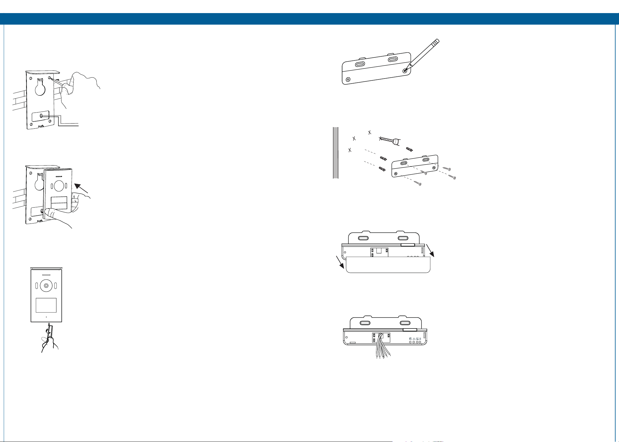
INSTALLATION
When installing the outdoor unit, make sure that the location you wish to install it is dry. It is important
that the camera or the electronics do not get wet.
1. Drill holes in the wall, insert the wall plugs in the holes. Place
the bracket and tighten the screws.
2. Connect the wires (see WIRING).
3. Mount the outdoor unit on the bracket. Make sure it is
properly secured.
INSTALLATION
1. Mark the installation location
2. Drill a hole in the wall, insert wall plugs and
screw unit onto wall.
4. Use the special security screw on the bottom of the unit, to
prevent theft.
5. It is possible to change the camera angle. Remove the unit
from the bracket. Loosen the screw at the back of the device
(right behind the camera), change the angle and tighten the
screw again.
3. Open the panel by the arrow direction
4. Pull the wires from the hole
Page 4

INSTALLATION
INSTALLATION
7. The green terminals into the 1.2
8. The orange terminal into the DC 15V IN
5. Take out the green terminal from accessories
bag, connect the wires to the outdoor unit
1
2
1
2
1
2
ON
DC 1 5V IN
9. Plug in the power and check the wiring is
correct
6. Take out the orange terminal from accessories
bag, connect the wires to the power
10. Cover the panel
11. Indoor-monitor to insert the smart bracket.
Page 5

Lock
Lock
INSTALLATION
HOW TO CONNECT AN EXTRA MONITOR
INSTALLATION
1. Take out the blue terminal from accessories
bag, connect the wires to extension unit
2. The blue terminal into the 3.4
Distance between units Wiring
1 - 50m
Power
ON
Power
1
2
1
2
1
A
B
C
D
2
1
2
1
2
3
4
Indoor Monitor
Additional
Indoor
Extension
Power
Monitors
3
4
1 - 100m
Extra indoor-monitors are optional, depending on how many indoor units you intend to use.
Page 6

USE
Intercom function: When in standby, when a visitor presses the call button on the outdoor
unit, the indoor-monitor will chime and you will see a live view of the visitor on the screen.
Press the intercom button to speak to the visitor.
Monitor function: Press this button on the indoor-monitor unit to see a live view of the
outdoor unit camera.
Internal Intercom: When in standby, press and hold the intercom button to activate
the internal intercom function. Use this to communicate between your different indoor
monitors.
Unlocking the door: After identifying your visitor, you can press this button to unlock the
door.
Unlocking the gate: After identifying your visitor, you can press this button to unlock the
gate.
Taking a photo/video: When someone rings the bell, it will take photo or video
automatically. In the call, Intercom, monitor state, pressing the button will take a photo or
video. The memory can store up to 100 photos, if storage is full it will written over the first
photo. Video files can only be stored in the TF card, if you don’t insert a TF card, you cannot
store video.
MAIN MENU
• Press the menu button to enter the main menu.
• Navigate the menu by using the left and right button. Confirm your selection with the OK button. Go
back a step with the Menu button.
From this menu you can enter the following submenu’s:
1. Video menu: You can browse through recorded
video clips.
1
2
3
2. Photo menu: You can browse through still
shots.
3. System settings menu: You can change various
settings from this menu.
SETTINGS MENU
1. Select photos or videos
2. Video time
1
2
5
6
3
4
7
8
3. Set number of photos
4. Adjust image effects
5. Adjust ringtone and volume
6. Date/time setting
7. Formatting
8. Version Information
ICON SUMMARY
Call
Monitor
Intercom
Internal call
Internal intercom
Unlock gate
Unlock door
Main menu
View video
View Photo
Menu settings
Photos
Video time
Set number of photos
Photo
Video
Adjust image effects
Adjust ringtone and volume
Time setting
Formatting
Version
Page 7

TECHNICAL SPECIFICATION
INDOOR MONITOR
Supply Voltage 15V 1A
Screen size 7” (diagonal) inch
Color configuration R.G.B.delta
Video System PAL/NTSC
Effective Pixels 800x3(RGB)x480
Consumption current 500 ± 200mA
Operation temperature -10˚C - +50˚C
Operation Humidity 85%(Max)
Picture Type JPEG
Video Type AVI
OUTDOOR UNIT
Imaging sensor type 1/4” CMOS
View angle about 100˚
Effective pixels 1288 (H) x 728 (V)
Minimum illumination 1Lux/F1.2
Night vision distance about 0.5
Effective window array 640 (H) x 480 (V)
Operating temperature -10˚C - +50˚C
Operating Humidity ≤85%RH
SAFETYINFORMATION
Precaution
Do not cover the ventilation openings with objects such as newspaper, table cloths, curtains etc.
Do not allow this product to get directly into contact with heat sources or naked flames.
The normal operation of the product may be disturbed by strong electro-magnetic interference.
This equipment is built exclusively for domestic use.
The device must not be exposed to splashes and it must not be submerged.
No object containing liquids, such as a vase, may be placed on the device.
Maintain a minimum safety distance of 10cm all around the product in order to insure proper ventilation.
Insure the outdoor unit is not installed where it may be covered by water or rain.
Do not allow children to play with the device
Conforms to all relevant European Directives
This symbol is known as the ‘Crossed-out Wheelie Bin Symbol’. When this symbol is
marked on a product or battery, it means that it should not be disposed of with your
general household waste. Some chemicals contained within electrical/electronic products
products or batteries can be harmful to health and the environment. Only dispose of
electrical/electronic/battery items in separate collection schemes, which cater for the
recovery and recycling of materials contained within. Your co-operation is vital to ensure
the success of these schemes and for the protection of the environment.
 Loading...