

Page 1
Smart Temp
Thermostats
TM
Model SMT-24
24 Volt Heat Pump or Heat Cool Thermostat
Two Stage Heating One Stage Cooling
Auto Changeover - Non Programmable
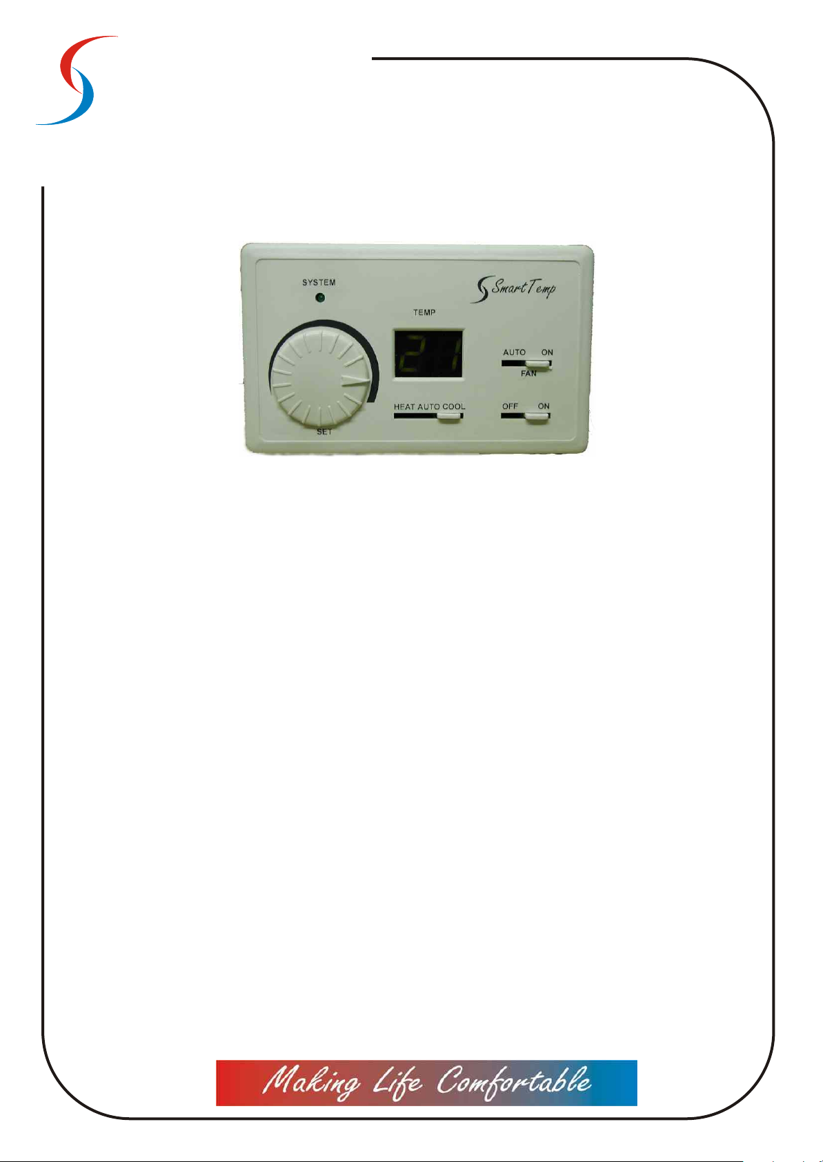
Operation
On Off switch
The system will operate only when this switch is in the “ON” position. When heating or cooling is not
required turn this switch to the “Off” position.
Heat Cool Auto switch.
Select “Heat” when heating only is required or select “Cool” when cooling only is required. In “Auto”
Mode the thermostat will automatically select heating or cooling mode depending on the current
room temperature and the set (or desired) Temperature.
Fan Switch
In the “Auto” mode the fan will only operate while the heating or cooling is running. The fan will stop
operating when the desired temperature has been reached and heating or cooling is no longer
required . Select “on” when continuous fan operation is required regardless of the need for heating
or cooling .
To Set Temperature.
The thermostat indicates the current room temperature on the illuminated display. When rotating
the temperature select switch the display will flash and indicated the SET or Desired temperature.
By turning the select switch clockwise or counterclockwise the desired or set temperature will
increase or decrease. After a few moments of not moving the temperature adjustment the display
will return to indicate room the current room temperature.
The thermostat will control the heating or cooling equipment and maintain the room temperature
to within ±1.5 deg C of the set or desired temperature.
System LED
This Green LED will illuminate when the thermostat requires the cooling or heating unit to operate.
Page 2
Smart Temp
Thermostats
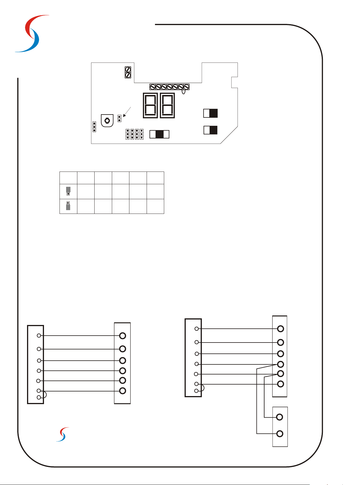
Optional Remote
Optional Remote
Sensor Connections
Sensor Connections
(P/n SMT- Sens)
(P/n SMT- Sens)
Jumper On =No time Delay
Temperature
Adjustment
JP1
TM
W1
/
W2 Y1 C RH RCG
BO
Factory Fitted link.
Remove when using
a two transformer
System
Fan Switch
JP2
JP4
JP3
JP5
Mode Switch
JP6
Off / On Switch
SMT-24a
Thermostat
W2
G
B/O
Y1
C
RH
RC
Jumper Table
Jumper
Position
External
Sensor
Internal
Sensor
Jp-2 OFF = 3 Min Time Delay
JP1 Internal / External sensor select.
JP2 Compressor Delay Select.
JP3 Heat pump or Heat Cool Select.
JP4 Fan Mode Select.
JP5 R/Valve energise select.
JP6 Display format (deg C or F).
JP3 JP4 JP5 JP6
JP1
Heat
Pump
Heat
Cool
Fan on
with
Heat Call
(Heat Pump)
Fan on with
system
(Gas Heat)
Rev Valve
Energize “O”
(cooling)
Rev Valve
Energize “B”
(heating)
Display
Deg F
Display
Deg C
Typical Connections
Typical Heat Pump System
Aux. Heat
Fan
Reversing Valve
Compressor
24V Neutral
24V Active
SMT-24a
Thermostat
W2
G
W1
Y1
C
RH
RC
Heat Pump Connections
W2 Aux Heat
GFan
W1/BO Reversing Valve
Y1 Compressor
C 24v Neutral
RH 24v Active Heat
RC 24v Active Cool
Heat / Cool Connections
W2 Heat 2
GFan
W1/BO Heat 1
Y1 Cool
C 24v Neutral
RH 24v Active Heat
RC 24v Active Cool
Typical Gas Heat with Add on Cooling System
Heat ( Stage2)
Fan
Heat ( Stage1)
Cool
24V Neutral
24V Active
TM
Smart Temp
Smart Temp Australia Pty Ltd
19 Indra Road Blackburn South 3130
Phone:(03) 9899 6455 Fax (03) 9899 6454
www.smart-temp.com.au
Australia
Limited One Year Warranty
24N
Cool
24 Volt
Cooling Relay
106052-1 RevA
 Loading...