

Page 1
Smart Temp Australia Pty Ltd
Unit 20, 1488 Ferntree Gully Road
Knoxfield Victoria 3180
Tel (03) 9763 0094
www.smarttemp.com.au
SMT-200 rev3
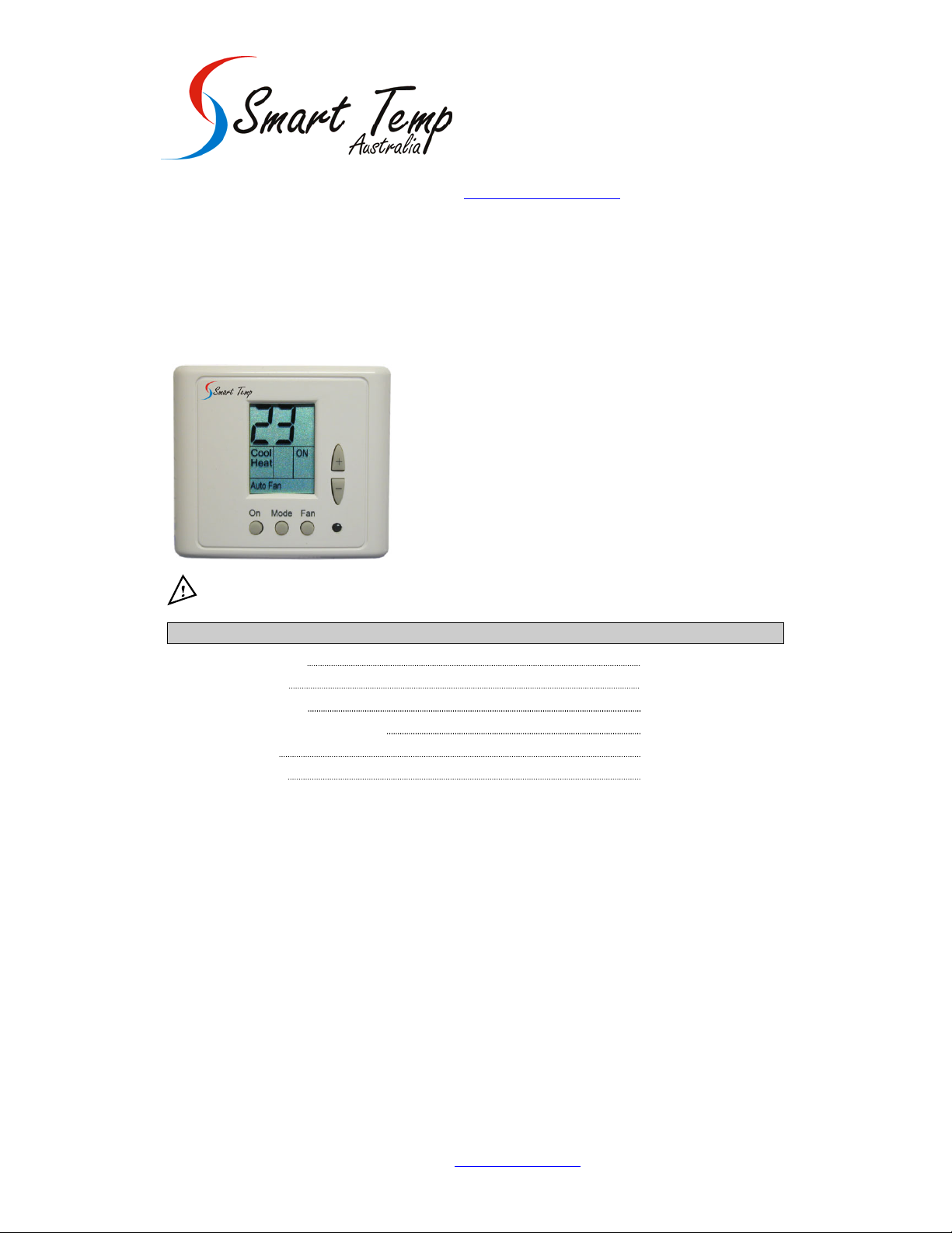
Owner’s Manual – Installation and Operating Instructions
Please read this manual carefully before installation and use.
Index
Installation Instructions 1
Wiring Connections 2
DIP switch Configuration 3
External Sensor Connection (option) 4
Operating Manual 5
Technician Settings 6
Model SMT-200 Rev3 Smart Temp Aust. 12/7/2007 www.smarttemp.com.au
Page 2
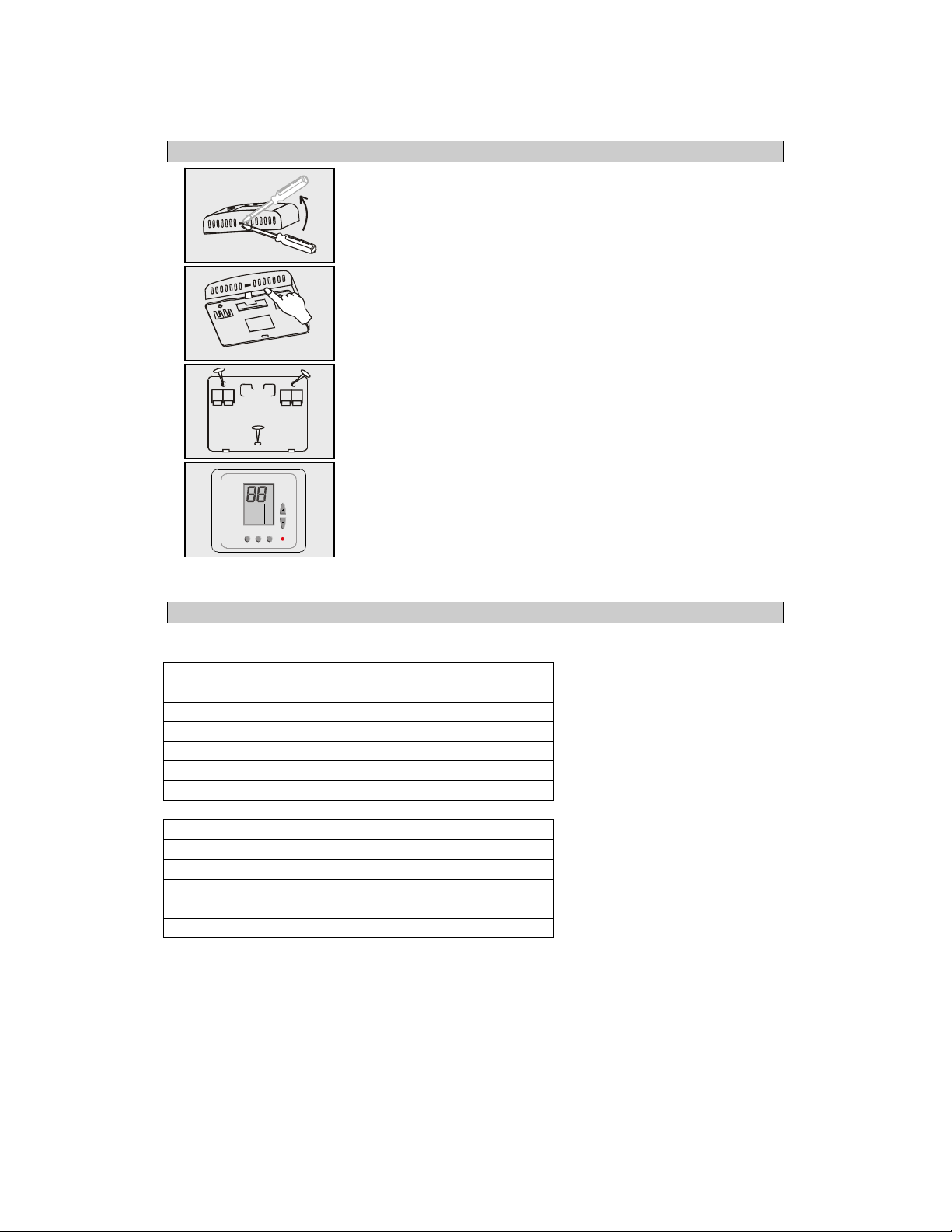
1. Installation Instructions
Cool
Heat
Auto
Fan
On/Off Select Prog
Setting
Separate the front panel from back panel by depressing the tongue
located in the top of the unit.
Pull the back panel out.
Line the back panel up again st the wall or flat surface. Install three
screws as required.
Make electrical connecti ons as shown on enclosed electrical wiring
diagram.
Install the cover to the back panel; first the two tabs on the bottom
and then the top tongue. Push until tight against the wall.
2. Wiring Connections
Choose the right configuration for your model.
TERMINAL FUNCTION
R 24 Vac ( Hot)
C 24 Vac (Common)
W3 B/O Heat 3 / Reversing Valve
W1 Heat 1
0 Window / Door Contact
IN Window / Door Contact
W2 Heat 2
To External Sensor
T External Sensor
Y2 Cool 2 / Compressor 2
G Fan
Y1 Cool 1 / Compressor 1
2
Page 3

3. DIP switch configuration
Location of DIP switches:
DIP switches
S2 S1
Factory default configuration for DIP switches:
S2 S1
Table 3.1 – DIP switch selection
DIP switch S1:
Func. Fan Mode in Econ. Time Delay
No.
Auto
Fan*
Continuous
4
Minutes*
No Delay**
1 OFF* ON X X X X X X
2 X X X X OFF ON* X X
3 X X OFF* ON X X X X
4 X X X X X X X X
5 X X X X X X X X
6 X X X X X X OFF* ON
X = Not important * = Default switch ** = No delay for compressor – for test only
DIP switch S2:
Func.
No.
Internal/External
Sensor
Internal
External Display
*
COOL &
HEAT
(HC##)*
HEAT
PUMP
(HP##)
Display of Room
1 ON* OFF x x x x x x x x
2 OFF* ON x x x x x x x x
3 ON* OFF x x x x x x x x
4 x x OFF* ON x x x x x x
5 x x x x x x OFF* ON OFF ON
6 x x x x ON* OFF x x x x
X = Not important * = Default switch
1 2 3 4 5 6
Cool only or All
modes
Cool
only
Temp
No
Display
1 2 3 4 5 6
Window Contact
All
modes*
OFF*
Change
Set point
“EC”
HC / HP configuration
HC configuration HP configuration
Electric.
Heat*
Gas
Heat
R/V in
Heat
R/V in
Cool
3
Page 4

4. External sensor connection - option
Important! The external sensor must be Smart Temp type.
N.TC. Sensor: Temperature ~ Resistance Characteristics
Temp °C
Temp °F
7.2 10.0 12.8 15.6 18.3 21.1 23.9 26.7 29.4 32.2
45 50 55 60 65 70 75 80 85 90
Res. k 115.8 100.9 88.1 77.1 67.7 59.6 52.5 46.4 41.2 36.6
The default from factory is INTERNAL SENSOR.
The length of the cable for the external sensor is 30 mete rs wit h st anda rd cab le.
If longer distance is required then shielded cable must be used.
There is a wide range of sensors for different appli c ati on s, duc t, room, et c.
For further details contact Smart Temp (03) 9763 0094 or www.smarttemp.com.au
.
5. Operating Manual
5.1 On/Off
• Press the ON/OFF button to activate or deactivate the thermostat.
• The word "ON" or "OFF" will appear in the display.
5.2 Set temperature
• Press the SET buttons (+) or (-) - the temperature will flash.
• Adjust the set temperature using the (+) or (-) buttons.
5.3 Selecting modes
Press the MODE button to switch between the four modes:
• Cool
• Heat
• Cool/heat (auto-change over),
• Fan only.
• Emergency heat selectable in heat mode in Heat Pump type (only).
Press and hold the MODE button (5 seconds) to activate Emergency
heat (Heat Elements ) and the compressor will be OFF.
This selection is for cold days when the outside temperature is very low and the
Heat Pump is active in heat.
To return back to Heat mode press and hold the MODE button again (only in Heat mode ).
5.4 Fan/Auto Fan function
• Press the FAN button to select AUTO FAN.
• Press the FAN button again to cancel.
In AUTO FAN the fan will only run when calling for heat or cool.
4
Page 5

6. Technician Settings
6.1 Setting temperature limits and offset
• Press and hold the “ON” button (5 second) – “50” will appear on display.
• Using the (+) button set the number to “55”.
Settimg Cool limit
• Press the ON button again - “COOL” will appear on display.
• Adjust set limit for cool using the (+) and (-) buttons.
Setting Heat limit
• Press the ON button again - “HEAT” will appear on display.
• Adjust set limit for heat using the (+) and (-) buttons.
Important: The user can change the set t emperatures on the disp lay regardles s of
the limit set, but the thermostat will only work to the required limits
Setting the offset (the offset is used for calibration of the measured temperature)
• Press the ON button again – the offset will appear on displ ay.
• Adjust set offset using the (+) and (-) buttons (range -6°C/+6°C – default 0°C).
Set point for cool in economy mode
• Press the ON button again - “AUX” and “COOL” will appear on display.
• Adjust set limit for cool in economy mode using the (+) and (-) buttons.
Set point for heat in economy mode
• Press the ON button again - “AUX” and “HEAT” will appear on display.
• Adjust set limit for heat in economy mode using the (+) and (-) buttons.
• Press the ON button again to return to normal display.
6.2 Lock/Unlock the thermostat’s buttons
Lock the thermostat’s buttons
• Press and hold ‘ON’ button (5 second) – “50” will appear on display.
• Set the number to “45”.
• Press the ON button again.
• Using the (+) button to Set Lock “Lc”.
Unlock the thermostat’s buttons
• Press and hold ‘ON’ button (5 second) – “50” will appear on display.
• Set the temperature to “45”.
• Press the ON button again.
• Using the (-) button to Cancel Lock “UL”.
5
Page 6

6.3 Door contact input
This input is normally open, can be used to connect door switch or window contact, etc.
The contact is Voltage free (2 terminals), normally open (activates when closed).
If the door contact closes the thermostat has two options (DIP switch selectable):
• Option A: The thermostat will be turned OFF.
When the contact closes, the display will show:
• Option B: The thermostat will cha nge the set point (Economy mode)
To change this options in the thermostat please refer to the dip switch explanation.
When the contact closes, the display will show:
When the thermostat set to OFF – the Door / window contact is not active.
OFF
Cool
ON
Heat
Auto Fan
Rev3.0 SMT-200 08-2007
6
 Loading...