

Page 1
Smart Temp
Australia
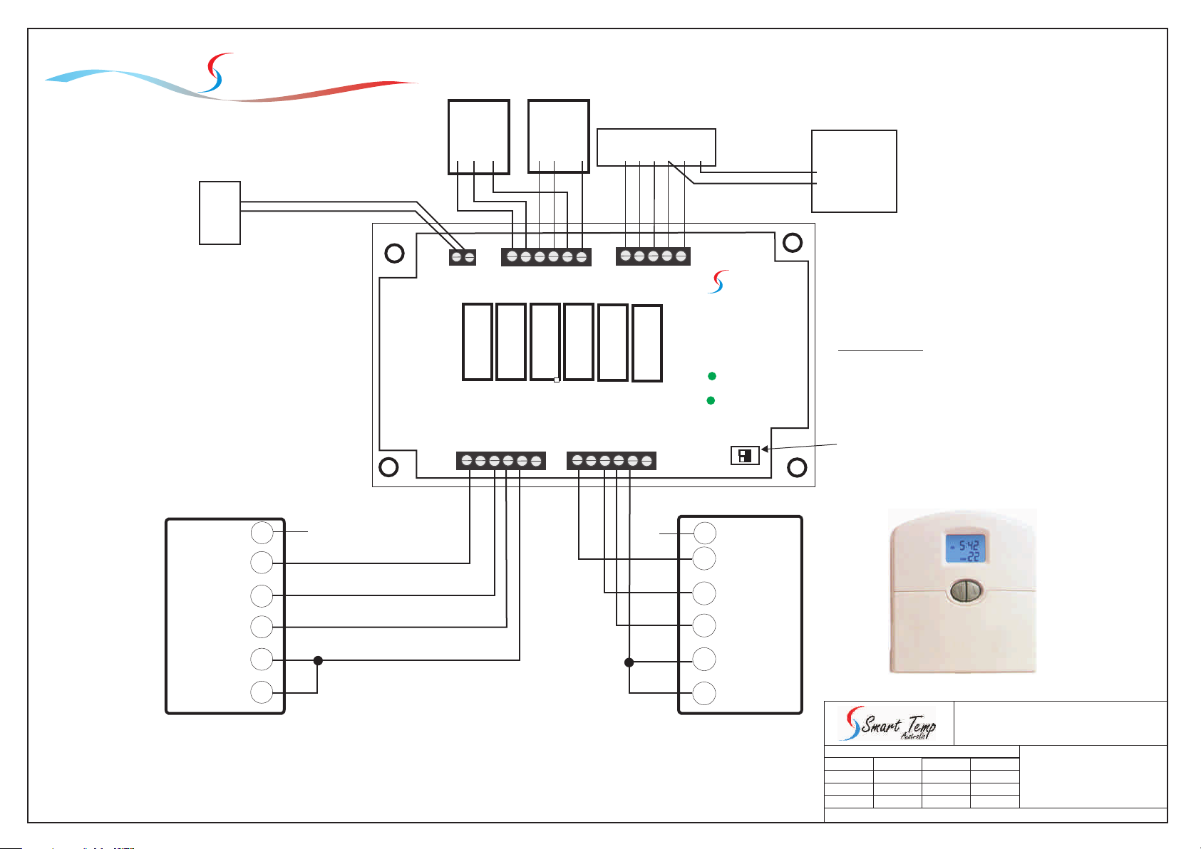
24Volt
Plug Pack
SZ-PS/24
Making Life Comfortable
Zone 1
Typical
24V
Drive open
Drive Closed
Actuator
2
3
Drive Open
Drive Closed
CAUTION
Wiring multiple zones in parallel
Zone 2
Fan
Typical
Heater
W
W2 YGR
Heat Stage 1
Heat Stage 2
C
Cool
Active
Condensor
Typical
Typical
24V
Drive open
Drive Closed
1
Common
Actuator
2
Red
1
3
Brown
Blue
Some actuators are not suitable for wiring in parallel
due to feedback from actuator. Please check with your
damper manufacturer to ensure your actuators are
suitable for parallel connection.
42157 Thermostat
Y1
W/B
G
Y/O
RC
x
R C
24V
Input
DC1
24V Dampers
C C G W1 W2 RIN
DC2
DO2
DO1
Max 24 Volt 3 Amps
Zone 1 Thermostat Zone 2 Thermostat
W1W1W2W2GGYYRRC
Y
Equipment
C
x
Smart Temp
Australia
SZ-2/24 Smart Zone
Two Zone Module
Z1
Diagnostic LEDS
Z2
ON
Y1
W/B
G
Y/O
RC
Diagnostic Led
Alternating Flash = Normal operation
Always ON = That zone thermostat wiring fault
Both Flashing = Time delay
For Heat Pump systems turn Sw1 & Sw2 ON.
Compressor is Y RV in Heat is W1
RH
Set Thermostat Switches to:
Sw4 = C
Sw3= HG
Sw6 = STD
RH
Drawing Revision History
29-05-2006
16-06-2004
Smart Temp
Installation Drawing
Drawing Name
Rev B
REV A
SZ-2/24
By JK
By: JK
Typical Wiring
with Smart Temp Thermostat
All care has been taken in the preparation of this drawing however
Smart Temp Australia accept no responsibility for damage that may
be caused by using this information. This is a guide only.
Ph:(03) 9763 0094
Fax (03) 9763 0098
www.smart-temp.com.au
 Loading...