

Page 1
Smart Temp
Australia
TM
RC
RH
C
Y1
Y2
W1/OB
G1
Smart Temp ISIS
CA 1 2 3
4
5
6 C
Transformer
FUSE
Relay 6
Smart Temp
Australia
240V 15Amp
FUSE
1
N
240V
P1 P17 P6
Com 1 2 3 4 5
A
30 Sec
Delay Start
Timer
P7
P2
ON
1
2
2
P13P11 P15
5
4
3
Relay 6
C
P8
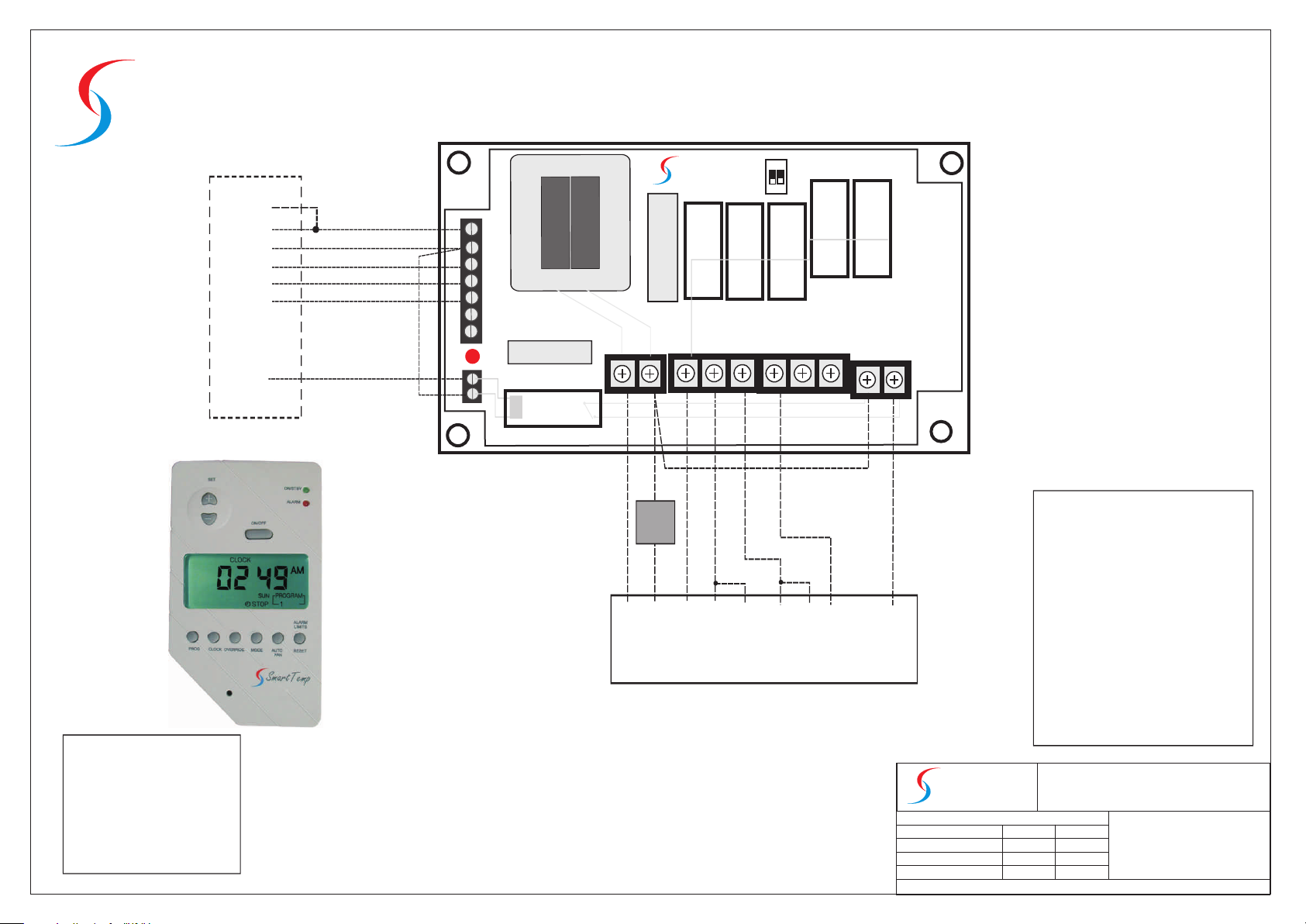
Daikin UATY 15,18,21 KY19
N/O
Interface
240V - 24V
Smartpak06
Daikin UATY 15,18,21 KY19 Connections
P1 - Neutral
P2 - Active to Thermostat
P17 - Reversing Valve
P6 - On/Off Fan Interlock
P7 - Safety Circuit Comp. interlock
P13 - Comp Run Signal 1st Stage Heat
P11- Comp Run Signal 1st Stage Cool
P15- Comp Run Signal 2nd Stage Heat
P8 - Comp Run Signal 2nd Stage Cool
ISIS Jumper Settings
JP1 A
JP3 OFF
JP4 ON
JP5 N/A
JP6 ON
JP7 ON
ALL CARE AND DILIGENCE HAS BEEN TAKEN IN THE
PREPARATION OF THIS INTERFACE DIAGRAM. SMART TEMP
AUSTRALIA PTY LTD WILL ONLY BE RESPONSIBLE FOR
DAMAGE CAUSED TO THE SMART TEMP PRODUCT, AND ONLY
IF IT HAD BEEN CORRECTLY APPLIED IN ACCORDANCE WITH
THE MANUFACTURES INSTRUCTIONS.
IT IS THE DEALER / CONTRACTORS SOLE RESPONSIBLITY TO
ENSURE CORRECT OPERATION OF THE MAJOR EQUIPMENT IS
MAINTAINED.
TM
Smart Temp
Drawing Revision History
04-05-2007
Unit 20, 1488 Ferntree Gully Road Knoxfield Vic 3180
Australia
Installation Drawing
REV 2.0
By: John K
Drawing Name
Dakin UATY15,18,21 Interfaced
with SmartPak06 and ISIS
All care has been taken in the preparation of this drawing however
Smart Temp Australia accept no responsibility for damage that may
be caused by using this information. This is a guide only.
Ph:(03) 9763 0094
Fax (03) 9763 0098
www.thermostat.com.au
Page 2
Smart Temp
Australia
TM
RC
RH
C
Y1
W1/OB
G1
Smart Temp ISIS
CA 1 2 3
4
5
6 C
Transformer
FUSE
Relay 6
Smart Temp
Australia
240V 15Amp
FUSE
1
N
240V
P1 P17 P6
Com 1 2 3 4 5
A
30 Sec
Delay Start
Timer
P10
P2
ON
1
2
5
4
3
2
Relay 6
C
P13P11
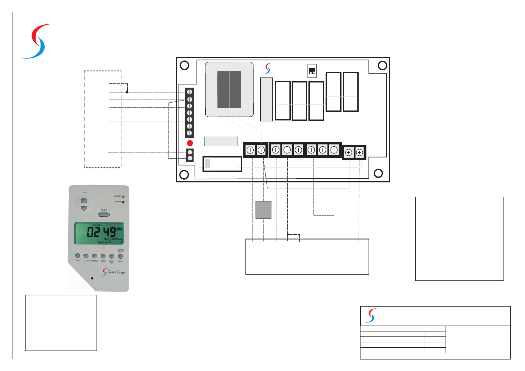
Daikin UATY 06,08,10,12 KY19
N/O
Interface
240V - 24V
Smartpak06
Daikin UATY 06,08,10,12 KY19 Connections
P1 - Neutral
P2 - Active to Thermostat
P17 - Reversing Valve
P6 - On/Off Fan Interlock
P10 - Safety Circuit Comp. interlock
P13 - Comp Run Signal 1st Stage Heat
P11- Comp Run Signal 1st Stage Cool
ISIS Jumper Settings
JP1 A
JP3 OFF
JP4 ON
JP5 N/A
JP6 ON
JP7 ON
ALL CARE AND DILIGENCE HAS BEEN TAKEN IN THE
PREPARATION OF THIS INTERFACE DIAGRAM. SMART TEMP
AUSTRALIA PTY LTD WILL ONLY BE RESPONSIBLE FOR
DAMAGE CAUSED TO THE SMART TEMP PRODUCT, AND ONLY
IF IT HAD BEEN CORRECTLY APPLIED IN ACCORDANCE WITH
THE MANUFACTURES INSTRUCTIONS.
IT IS THE DEALER / CONTRACTORS SOLE RESPONSIBLITY TO
ENSURE CORRECT OPERATION OF THE MAJOR EQUIPMENT IS
MAINTAINED.
TM
Smart Temp
Drawing Revision History
04-05-2007
Unit 20, 1488 Ferntree Gully Road Knoxfield Vic 3180
Australia
Installation Drawing
REV 2.0
By: John K
Drawing Name
Dakin UATY06,08,09,10 12 I
interfaced with SmartPak06
and Smarttemp ISIS
All care has been taken in the preparation of this drawing however
Smart Temp Australia accept no responsibility for damage that may
be caused by using this information. This is a guide only.
Ph:(03) 9763 0094
Fax (03) 9763 0098
www.thermostat.com.au
 Loading...