

Page 1

SMT-880 Falcon
User and Installer
Manual
Version 3.1
Page 2

Page 2 DRAFT
Version History
Version 1
September 2013
Original Document
Version 1.1
November 2013
Improved manual layout
Added 0-10 Function
Version 1.5
January 2014
Grammar errors in manual corrected
Added PI control
Improved HP logic
Version 2.0
December 2014
Added Wi-Fi
Version 3.0
June 2018
Revised Hardware to combine Zone and UCC board into 1 PCB
Version 3.1
December 2018
Added Inverter Module Information
Welcome
Thank you for purchasing the “Falcon” thermostat from Smart Temp.
This product has been built to the highest standard to ensure your home comfort levels are maintained
as simply and efficiently as possible.
Please take the time to read this manual so that you can gain maximum benefit from this advanced
product.
Page 3

Page 3
Table of Contents
Version History 2
Welcome 2
Table of Contents 3
Introduction 4
Setting up your Thermostat 5
Navigating through Menus 5
Icons, Buttons & symbols 5
Understanding the Home Screen 5
Masters and Slaves 8
Setting your comfort Levels 8
Selecting your Mode 8
Setting your Temperatures 9
Setting your Schedule 10
Smart Fan (Commercial) 10
Manual Mode 10
Zoning 11
Zone Overview 12
Zone Icons & Control 12
History Button 14
Setting Holidays 14
User Settings 15
Connecting to the Internet 16
To monitor your falcon via PC 17
Installer Settings 18
Overview 18
Unit Control Card 18
Wiring Examples 21
Controlling Digital Inverter Systems 22
Wall Controller Connections 23
Wall controllers Wiring 23
Zoning 24
Zone Wiring. 24
Understanding the Zone Settings 24
Ancillary Devices 27
Installer menu 28
Page 4

Page 4 DRAFT
Introduction
The Falcon is a home comfort control system designed to be simple to use and still provide powerful and
energy efficient climate control. The Falcon offers many advanced features to give greater control of home
(or office) comfort than a conventional home thermostat could achieve. The Falcon is the next generation
of home comfort control systems.
Some of the Falcon features include
Multiple wall controllers – up to a maximum of 4 wall controller can be used. All wall controllers
are networked so that a change made on any one wall controller will be updated to all others
automatically.
Temperature control climate zoning – up to a maximum of 9 zones can be installed. Set individual
times and temperatures into every zone if required or run zones manually if this is your
preference.
Connection to the internet for remote access.
Digital Photo Frame function. Use the wall controllers to display pictures if desired.
The Falcon will be configured by your installer to meet the design of your heating and cooling system and
to offer you the best performance from this system. As such, not all features and functions detailed in this
manual may be available with your Falcon.
You should discuss the availability and suitability of various options available for your Falcon with your
installer or with your Smart Temp or authorised distributor.
I encourage you to take the time and read this manual so that you may benefit from many innovative
features and functions your Falcon offers.
Page 5
Page 5
Setting up your Thermostat
Your Falcon is a remarkably easy controller to use. Its touch interface and graphical display will guide you
as you set up and use the Falcon to control your comfort levels.
Navigating through Menus
Icons and menus are used to prompt you through the various settings and options within the Falcon.
These functions are described below.
Icons, Buttons & symbols
Icons
Taping an icon will take you to a new page where you may have a number of options to select from and
or adjust, or you may simply be given some information.
In many cases if you had made a change to a setting - you must press “Done” to save these changes before
you exit or the changes you have just made will be lost.
To exit one of these windows select Exit or Back.
Note If the Falcon screen has not been touched within 90 seconds, it will automatically default to the
Home Screen. You may lose any changes you have made if you have not pressed “Done” before the Falcon
auto exits.
Buttons
A button most time performs a specific function, such as “Done” that saves a change. A button can also
toggle something on or off.
Changing options
In many of the Falcon menus you will see an option shown in blue, with the currently selected value shown
next to it in red, such as “Display C/F C”. Touching that line will select that option and highlight the value
to be changed in in yellow. You are then able to alter the highlighted option using the up and down
buttons. In this example, change the Falcons temperature display from degree Celsius format to degree
Fahrenheit or visa versa.
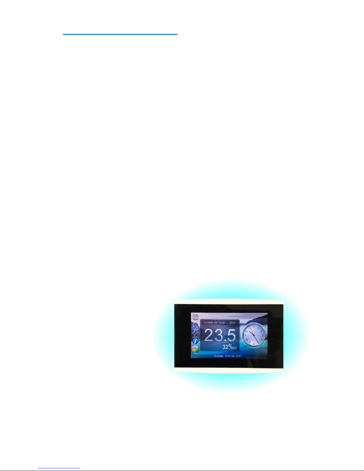
Understanding the Home Screen
Whenever the Falcon is left idle it
will return to the Home Screen.
From here you have access to all
of the features and functions that
your Falcon offers simply by
touching one of your short cut
icons shown on the left edge of
the Home screen or touching the
“More” icon and having access to
all the Falcons Icons.
Your home screen can be
customised in many ways to suit
your lifestyle or décor. For
example, the wall paper (Image shown behind the time, temperature, and other icons) can be selected
from a library of pre- installed images. Your installer can also load additional images should you wish.
Page 6
Page 6 DRAFT
Your Falcon can be set to act as a digital photo frame when idle, simply touching the screen will return
the Falcon to the standard Home screen where you are then able to make selections. (Note - there may
be a few seconds delay if the Falcon is currently arranging image files ready for display.)
Items such as backlight levels as well as many other parameter can be set to tailor your Falcon to your
needs.
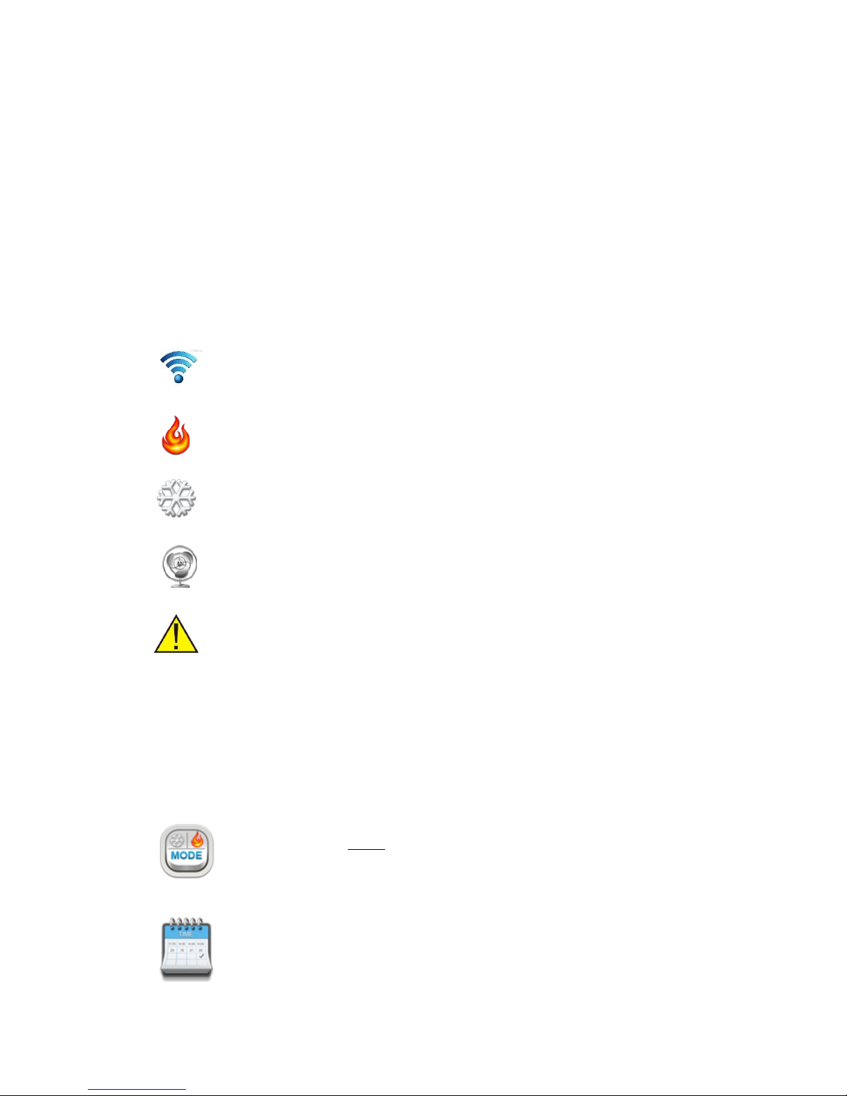
Status Bar
The lower section of the Home screen shows the status bar. In this bar the date is shown along with other
symbols that provide feedback about the Falcon operation.
Time & Date
The Falcon will show the current time and date. This can be set manually in
the settings menu or set via the internet based on your location if you have
your Falcon Wi-Fi network enabled and active.
Wi-Fi Icon
Tapping this icon will open a page that will permit you to setup and confirm
the status of the Falcon Wifi
Heating
If your Falcon has called for you AC system to provided warmth, the flame
symbol will be shown.
Cooling
If your Falcon has called for you AC system to provided cooling, the
snowflake symbol will be shown.
Fan
If your Falcon has called for you AC system fan to run (without the need for
heating or cooling), the fan symbol will be shown.
Error
The error icon will be shown whenever the Falcon detects an internal or
system error. Touching the Error icon when it appears will open a window
detailing the issue and in most cases suggest a method to solve the
problem.
Icons
Icons provide you with a simple method to change between screens of data or functions. Taping a Icon on
the left side of the screen will open the function associated with that icon.
Mode Icon
Used to select the master Falcon operational mode and fan control.
See “selecting your Mode” on page 8
Schedule Icon
Used to set your desired temperatures and program your daily events. (Only shown
if Zoning is disabled). See “setting your temperatures on page 9)
Page 7

Page 7
Zone Icon
When zoning is enabled this icon will permit you to access the individual zones
setting and status window. (only shown when Zoning is enabled) See “Settings
Zones” on page 11.
History Icon
Tapping this icon will permit you to view a moving 7 day history of the heating &
cooling set points as well as the room temperature. If zoning is enabled you will be
able to view the history for all fitted zones. Note – If multiple wall controller are used
the History Icon will only available on the “Master” wall controller. (See page 14 for
more information on this function.)
Holiday icon
The Falcon can be set to maintain an alternate comfort level whilst away on holidays.
(See “setting Holidays” on page 14 of this manual)
Info Icon
This icon will provide you with information about your system as well as the contact
details of your installer.
Settings Icon
When you need make changes about the way your Falcon looks and operates tap the
setting icon to open the settings menu. The functions in this menu are described on
page 15 of this manual.
Installer Icon
The Falcon is capable of controlling many different types of Air Conditioning systems
and as such offers many options for the installer. Adjusting settings in this menu
requires knowledge of the air conditioning system functions and as such a security
PIN is needed to protect the AC system and to prevent “uninformed” settings
changes. It is highly recommended that you don’t make changes in this menu unless
you know what impact these changes will make on system performance and
function. Information on the installer options are shown on page 16 of this manual.
Docked Icons
The Falcon Home Screen has 5 “docked” shortcut icons on the left side
of the Home Screen. You can select your preferred icons that you wish
to occupy these positions. The “More” icon position is locked and
cannot be moved.
Should you wish to place your preferred icons on the Home Screen
simply touch the “More” icon to take you to the “More” screen. Press
and hold the icon you wish to dock on the Home screen for 5 seconds and a small window will pop up
showing the 4 currently docked Home screen icons. Simply touch the icon you wish to replace with the
selected icon.
Page 8

Page 8 DRAFT
Masters and Slaves
Your Falcon is a great deal more than a simple single home or office wall thermostat. Your Falcon system
can comprise of up to 4 wall controllers that all communicating with each other as well as with the nine
temperature-controlled zones. 1 Master controller and three slaves yet all operate equally.
With the Falcon system you are able
to adjust any zones settings from any
of the 4 wall controllers. For
example, check the nursery
temperature from the master
bedroom, or turn off the kid’s
upstairs rumpus area off from the
kitchen when they forget and go out.
As power as the Falcon can be, it is a very simple system
to operate. It offers Intuitive functions with logical layout.
Setting your comfort Levels
The Falcons base function is comfort level control. It does this by comparing the current room
temperature with your desired target (or set) temperature. It then intelligently commands the AC system
under its control to supply warmed or cooled air into the Home or office and to the appropriate arrears
of your home or office if the optional zone control module is fitted.
The Falcon can maintain a single set temperature or automatically vary the temperature throughout the
day and night to match your lifestyle if you enable scheduling.
Selecting your Mode
Tap the MODE icon to change your control modes.
Your Falcon can operate in heating only mode, cooling only mode and auto mode.
Additionally, the Falcon can also control a single or multispeed fan system in a number of
ways.
Please note - It is important that you select the most appropriate mode for your needs. For example, if
your Falcon mode is set to heat only mode and your home/office or one of your zones require cooling
(provided the optional zone control module is fitted) then the Falcon will not request cooling for that zone
regardless of the zones cool set temperature. In heat only mode you have limited the Falcons control
ability to heating only – No cooling is provided and the “Cooling Wait” icon will be shown. This is also true
if your select cooling only mode. Your Falcon will provide heat to your home or office.
Off
There will be NO heating or cooling in your home or office - even if the room temperature rises or falls
above desired levels. Holiday schedules will not be used.
Heating Only mode
In heating only mode, your Falcon will control your AC system to warm your home or office. It will not
cool your home or office regardless of how high your home or office temperature becomes.
Cooling Only mode
Page 9

Page 9
In cooling only mode, your Falcon will control your AC system to cool your home or office. It will not heat
your home or office regardless of low your home or office temperature becomes.
Auto Mode
In Auto mode, your Falcon will decide whether to activate your heating and cooling system to maintain
your home or office to your preferred comfort level. This mode is recommended, particularly if you have
the optional zoning module fitted.
Fan Auto
Fan Auto mode will intelligently control your AC fan in the best way to maintain your desired home
comfort levels. It is highly recommended you leave your fan in Auto Fan Mode. The Fan will turn on when
needed and off again automatically when not needed.
Fan Continuous
If you select continuous fan, the AC fan will not stop but continue to run endlessly provided the Falcon is
NOT supplying warm or cooled air to satisfy comfort levels. This can be good to improve the “stuffiness”
of your home or office but may conflict with any zone control settings you may have.
Fan Speed (If Fitted)
You are able to manually select a fan speed or, let the Falcon choose the most appropriate fan speed for
you. It is highly recommended that you leave this setting in Auto speed.
Setting your Temperatures
Tapping the
Program icon will
open the
programming window shown
here. In this window you are able
set your comfort levels as well as
make other adjustments as shown
below.
Temperature
This large display in the centre of
this window displays the current temperature and the mode - whether the temperature is Ok or being
heated or cooled.
Heat and Cool set point
Tap the Heat up/down buttons to adjust the current
heat and cool set points to your preferred value. Note,
the heat and cool set point push each other away to
maintain a pre-set spread. At no time will the Falcon permit you to set the heat set point above the cool
set point. The Heat set point will always be lower than the cool set point.
When you adjust your heating or cooling set temperature an option box will open where you can choose
how long the new set temperatures will last (if programming is enabled) or how long you would like the
system to continue to control at these temperatures before automatically shutting down if manual mode
is selected. Simply tap the desired override period within 4 seconds and this will be set. If you fail to make
a section within 4 seconds the Falcon will automatically choose 2 hours by default.
You are given the option to cancel this override at any time should you wish by pressing the “Cancel
Override” button.
Page 10

Page 10 DRAFT
Setting your Schedule
Your Falcon can automatically alter the set
temperatures to match your life pattern.
In this way the Falcon can turn your AC
system down or off while sleeping and
bring it back on at the end of the night in
preparation for your days activities.
Tap the schedule button and the Falcon
will show you the schedule window. As
selected by your installer your Falcon may
have between 2 to 6 daily schedules. The schedule names are also able to be customised by your installer.
The picture above is a typical example.
Tap the day (or multiple days) to select a single day or a group of days to adjust. (Selected items will be
highlighted). You then select the Heat or cool set point or the time you wish to adjust, again these will be
highlighted. Use the Up/Down button to make these adjustments then press ”Done” to save changes.
(Tip – double tapping a temperature in the schedule window will toggle it between the previously set
temperature value and OFF, meaning that for that scheduled period heating or cooling will not run.
If a particular zone does not require all of the events you are able to disable an event period just for that
zone. For example, there may be 4 events set (Wake, Leave, Return, Sleep) and a particular zone may
only want to be on between 5pm and 7 pm requiring only two events (Return and Sleep). Press and Hold
the event that you do not wish to use, such as the wake event and its name will turn red and the heat and
cool set points will disappear. This event is no longer used and will be skipped.
Smart Fan (Commercial)
If enabled by the installer your Falcon can automatically swap between Fan On mode and Fan Auto modes
for each or any of your daily scheduled events.
Tap the schedule name to set the fan status to Continuous Fan mode for the selected programmed event.
A Fan symbol will appear to the right of the event name to indicate this mode is active for the event and
the fan will run continuously during that event. The fan mode will return to Auto Fan mode at the next
scheduled event, when the return event starts as shown in the example above.
At any time you are permitted to tap the “Mode” icon and change fan modes however at the conclusion
of a Smart Fan event, your Falcon will automatically reset your fan mode to Auto Fan.
Note – If zoning is enabled in your Falcon, only the zone 1 schedule will be used to set the Smart Fan
function in your Falcon.
After you have made your changes press “Done” to save changes or back to exit without saving changes.
Manual Mode
By selecting “Manual” you will disable programming from your thermostat.
Your thermostat will maintain your set temperatures until you manually
adjust them to a new value.
Page 11

Page 11
To enable manual mode for your Falcon (or just one zone if zoning is enabled – Note manual mode is only
available to zones fitted with temperature sensors) press the “Manual” button from the schedule window.
A confirmation box will pop up to ask if you are sure you wish to disable programming. Select “YES” to
proceed or “BACK” to return to the previous window.
In “manual mode” you simply set your desired heating and cooling temperatures. These are maintained
until you alter them manually in the future. You are also able to set an “Auto Off” timer should you wish
with manual mode by taping a temperature select button. A window will open asking how long you wish
to maintain this temperature before automatically turning off. This works in a similar way to the override
timer set previously.
Zoning
The zone icon is only visible if zoning is enabled on your Falcon. The Zone icon replaces
the schedule icon.
Zoning is the ability to use one single AC system and then break that single system up into
a family of virtual smaller AC systems - one for each area or “Zone” of your home or office.
Each zone can have its own temperature sensor, its own set (or desired) temperatures and its own
schedule if desired. You can even have a mix of programmable and manual zones should you wish.
If you think of zoning your home heating and cooling in the same way you consider lighting your home or
office. You don’t have one single light switch in your home that turns every light on or off, you turn lights
on or off in the areas of your home as you need them. This same principal applies to temperature zoning.
Depending on how your Falcon has been configured by your installer you have the following options.
Basic Zone control.
All zones are individually temperature controlled (if sensors are fitted) to your single desired heating and
cooling set temperature. You are not permitted to open or close zones.
Normal Zone control.
All zones are individually temperature controlled to your single desired heating and cooling target
temperature. You are permitted to open or close zones as room occupancy or needs change, but all zones
will attempt to maintain the same temperature (Typically used in commercial buildings).
Advanced Zone control. (Default)
All zones are completely independent of each other, Zone temperature and scheduling is completely
independent and different temperature and times can be set for each zone. Advanced zone control is best
thought of as a place where every area had its own AC/system and its own thermostat.
Variable Zone Control
Page 12

Page 12 DRAFT
This mode takes advantage of some of the newer variable capacity types of A/C systems where their
output can be increased or decreased based on the demand your home or office places on the system.
The Falcon is able to calculate demand and provide that information to the Air Conditioning system.
Zone Overview
Taping the zone icon opens the Zone
window. In this window you are given
an overview of the status of all zones
and the ability to adjust individual zone
settings if required.
In this example you can see that nine
zones are fitted, the individual zone
temperatures are shown (when the
optional zone temperature sensors are
fitted) and whether the temperature in
that zone is ok (at temperature) or requires heating or requires cooling. You will note that each zone has
its custom name, helping identify the zone for another.
Zone Icons & Control
The Zone Icon shown provides you with information about that zone. The
zone name (so that you can easily identify that zone). The current Zone
Temperature (if a temperature sensor has been fitted to the zone) and the
zone status as described below.
This zone has requested and is receiving warmed air.
This zone has requested warm air however the Falcon is waiting before providing heat to this
zone.
This zone has requested and is receiving cooled air.
This zone has requested cooled air however the Falcon is waiting before providing cooled air to
this zone.
This zone temperature is OK.
OFF
This zone is OFF and will not receive conditioned air regardless of the zone temperature.
Zone Temperature Monitoring & Control.
You will see that some zones in the above example show you the zone temperature along with the zone
status. Zone 9 in the example above does not show any temperature value as a temperature sensor has
not been installed in this Zone. In this case all you are permitted to do is open the Zone (On) or closed the
Zone (Off). The zone when open will receive warmed or cooled from the AC system regardless of the
temperature in that zone.
Page 13

Page 13
“Wait” - Zone Message explained
Your AC system can supply either warmed air or cooled air at any given time. It cannot supply both
warmed air AND cooled air at the same time to different zones. The Falcon knows this and will supply
warmed air to the zones requiring it and the zone requesting cooled air must “wait” for the other zones
requiring warmed air to be satisfied. Likewise, should the Falcon be currently providing cooled air, the
zones requesting warmed air must wait.
The Falcon also knows that a large AC system can be damaged when it is turned on without the proper air
flow being available to it. So, if only a small part of your home or office is calling for heating or cooling the
Falcon my wait until there more outlets demanding conditioned air before starting the AC system. In this
case it will wait for more zones to call.
Additionally, the Falcon knows how much heating or cooling capacity is available in your AC system and
whether there is enough to satisfy your home or office. If the demand on the AC system is too great, the
Falcon will make zones of lower importance wait for heating or cooling while it satisfies the zones that are
more important. Again, it will ask these less important zones to wait.
Lastly, if a zone is requiring heating for example but the Falcon mode is set to Cooling only (or OFF), then
the zone requiring heating will wait for you to enable the heating mode. (See modes on page 8).
Naming the zones
To make the Falcon easier to use, you
are able to give each zones a unique
name. In the zone control window
simply press and hold the zone you wish to name. The display will change showing a keyboard permitting
you to edit or change the zone name. Tap done to save changes.
The Zone Setting window
(IF Zone temperature sensor fitted). This looks similar and functions in an identical manner to the
temperature window shown on page 9 of the manual. All the same features and functions apply. The
Falcon simply provides those same tools for each of your zones fitted with a temperature sensor, including
scheduling, manual mode and temperature override etc.
Zone mode
Tap this to switch between Zone Off or On.
Zone OFF
This zone will not receive conditioned air.
Zone ON
You will be given the option to set a desired zone temperature and apply a schedule (if the
zone is fitted with a temperature sensor). This zone will now control the AC system and air
flow to this zone to maintain the zone heat and cool set point. Zone ON is only shown if a
temperature sensor is fitted for this zone
Page 14

Page 14 DRAFT
Copy Button
Once you have programmed a zone with
your scheduled time and temperatures
the Falcon permits you to “copy” that
schedule to other zones. In this way, you
are able to easily program all 9 zones
within a few moments.
Copy To
Simply select “Copy To” to take the
current zone you have just programmed
(Kitchen in the example shown with black
text) and copy the Kitchen settings to the zones you require. Tap each zone to select, they will highlight
green and press Done to begin the copy process.
Copy From
Rather than set up a zone schedule for a zone from scratch, simply select the copy button from within the
zone, then copy from and the zone you wish to copy. Press done.
History Button
Touch this icon to open the history
window. This provides a 7-day running
history of the set temperature and the
room temperature. If zoning is enabled
you are provided with data for each zone
Using the Prev or Next button enables
you to navigate through the various
zones temperature log.
Tapping the graph on any zone will
permit you to zoon onto an individual day’s data.
Setting Holidays
When you expect to be
away from your home or
office for some time, you
may want to enable the
“holiday” function.
Tap the “Holidays” Icon and the
“Holiday” window will open.
Simply select the desired heating and
cooling set temperature you wish to
maintain while you are away as well as
he time and date of your expected
return. Then simply select ON. The Falcon will open all zones and control your heating and cooling system
to maintain your desired temperatures as measured at wall controller 1.
If holiday mode is active - the Main screen will show “Holidays” in the status bar.
Fresh Air
If your home or office has outside air economy cycle option fitted, the Falcon will automatically introduce
outside air into your home or office each day for the specified amount of time. It will do this in blocks of
Page 15
Page 15
15 minutes or more. So if you select 30 minutes of fresh air per day the Falcon will introduce 15 minutes
of air in the morning and 15 minutes of fresh air in the afternoon.
Active ventilation
If selected, the Falcon will start up and run your AC fan for the specified period of time to circulate your
indoor air to maintain freshness. It will do this in blocks of 15 minutes or more. So if you select 30 minutes
of active ventilation per day the Falcon will introduce 15 minutes of air in the morning and 15 minutes of
fresh air in the afternoon.
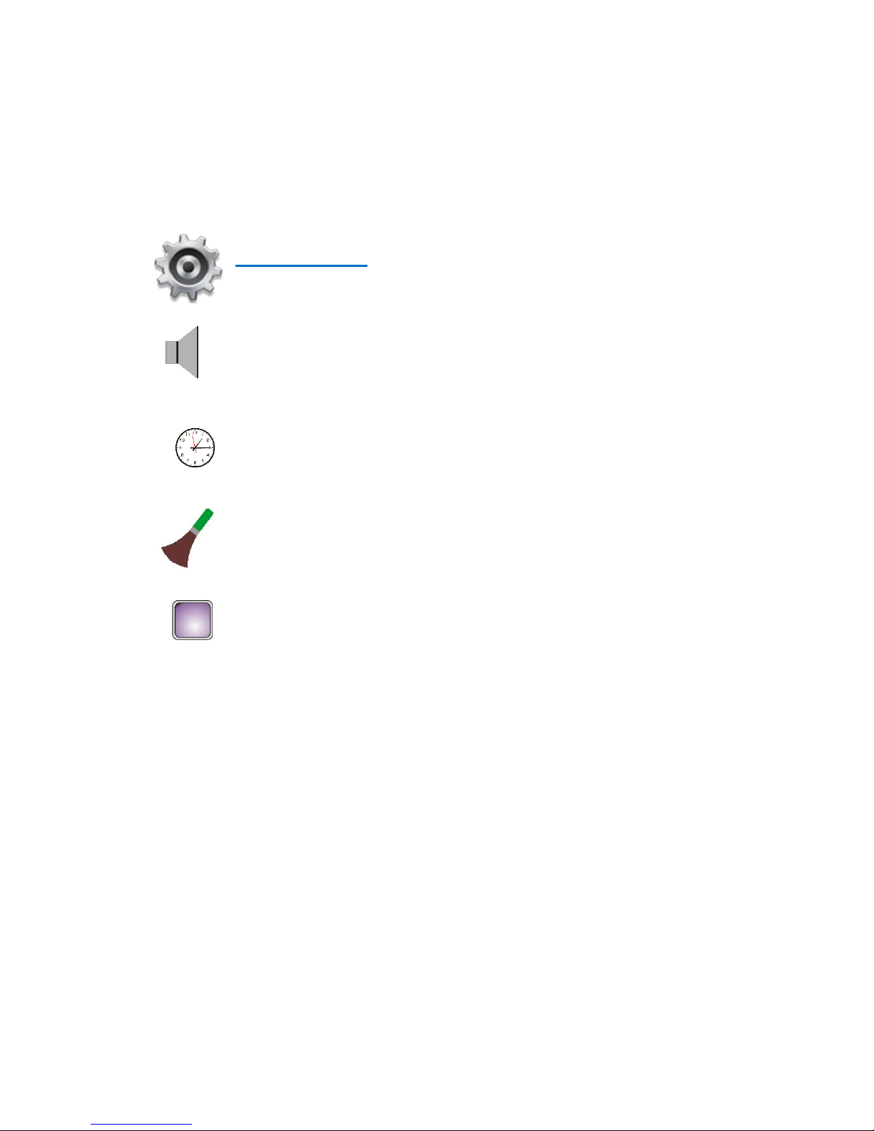
User Settings
The Falcon offers a settings menu that permits adjustment to the way your Falcon looks
and operates. A description of each function is provided below.
Speaker
Tapping the Speaker icon toggles the audible beeper on & off.
Clock
Tap the clock Icon to open the Time & Date settings window. Simple use the Up/Down
buttons to set the Falcon to the correct date and time or check the “Use Internet time”
box if connected to a Wi-Fi network with internet access.
Brush Icon.
Tapping the Brush disables the touch screen for 30 seconds to permit you to wipe the
screen without effecting the Falcon operation or settings.
Display
Tap the display Icon to enter the Display settings window. In this window you have 3
tabs across the bottom of the screen. Tap the tap to revel the options you wish to adjust.
Wallpaper Tab
There are many wall paper options that you can choose that sit as a background behind the main screen
icons. Select the wall paper you wish to use and select “Preview” to see the wallpaper or “Done” to use
the currently selected wallpaper. Once you are happy with your selection press “Exit” to save your changes
and exit the window.
Options Tab
The options tab permits you to adjust the following by touching the value you wish to change, it will
highlight yellow. You must press “Done” to save changes.
Date format
Sets the display format for the date - Your options are DD/MM/YY or YY/MM/DD
Time Format
Sets the display format for the time - Your options are AM/PM or 24 hours
Mood Lighting Level
There are a number of small coloured lights on the rear of the Falcon that will cast a glow on the wall in
dimly lit rooms that are designed to improve the visual appearance of the Falcon. Your options are “Off,
Always Bright, Day Only or Night Only.
Mood lighting Pattern.
Page 16
Page 16 DRAFT
If mood lighting is enabled you can select the way it operates. Selecting “Random” will slowly cycle
through the colour spectrum. Selecting “System Mode” will cause the Lights to glow red when heating,
blue when cooling and green when the room (zones) are ok.
Digital photo frame.
The Falcon is fitted with a SD card to which you can load “JPG” images and have the Falcon display these
images when idol (Not being touched). Note - As the Falcon is primarily a thermostat most of its computing
power is dedicated to comfort control, therefore if using the digital photo frame function the Image size
must be 800 x 480 pixel. (There are many free programs are available on the internet that can re-size JPG
images). These JPG images should be loaded into the root directory of the SD card.
As the Falcon works to de-compress and load images the Falcon will display a “please wait” message for
approximately 15 seconds before the next image loads. During this time, the touch function is disabled.
Transition time
The Transition time sets the duration that each image is shown before being replaced by the next image
on the SD card.
Backlight
The Falcon is fitted with a light sensor that can automatically control the backlight level based on ambient
light levels in the room. These values can be found in the display menu.
Day Active level
The backlight level when the LCD is touched when the room is lit.
Day Inactive level
The backlight level when the LCD has not been touched room is lit.
Night Active level
The backlight level when the LCD is touched when the room is dark.
Night Inactive level
The backlight level when the LCD has not been touched room is dark.
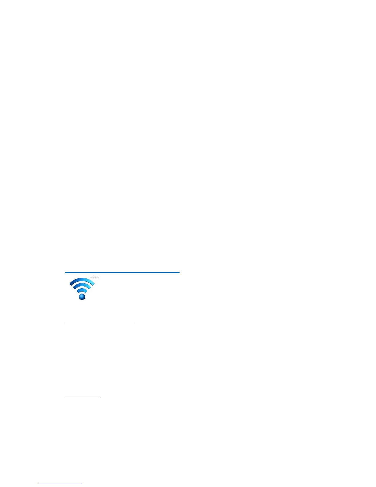
Connecting to the Internet
Your Falcon system is fitted with a Wi-Fi radio to permit you to connect your Falcon to
the internet. This will provided you with the ability to control most of the Falcon functions
from anywhere in the world where you have internet access.
The steps for setting up your Falcon are
On the Falcon Wall controller
1 Using the falcon touch screen tap the “More” icon on the main screen.
2 Tap the Wi-fi icon.
3 Click the “Enable Wi-Fi” check box.
4 Press Setup connection.
5 Press Scan to scan for all available Wi-Fi networks in range of your falcon.
6 Select your network and enter your network password and press done.
7 Your Falcon will try to connect, if successful it will show a QR code in the display.
On your phone
1 Log onto the Apple App store or Android Store and download the Smart Temp thermostat
app onto your Wi-Fi enabled smart phone or tablet.
2 You will need setup a new account by entering a user name, email address and password.
The email address is only used as it is unique identifier.
3 Respond to the confirmation email that has been sent to you to confirm the account.
4 Open the Smart Temp App.
5 Select “Add New Device” and select QR code method.
Page 17

Page 17
6 Scan the QR code using your smart phone camera and enter the displayed password
To monitor your falcon via PC
Open a web browser and enter the address www.thermostat.com.au/portal. Or visit our webpage at
www.thermostat.com.au and click the “Portal Log In” button on our page.
You will be presented with a log in screen, enter your email address and password. (Remember your email
address and passwords are case sensitive).
A welcome screen will be show. A list of all the Smart Temp devices associated with your email account
will be shown.
Click on the location and the device you wish to view or adjust.
Page 18
Page 18 DRAFT
Installer Settings
Caution. The information provided in this section is intended for the use of qualified personal only.
Changes made to the Falcon in this section can have a big impact on the AC system performance and life.
Do NOT make changes in this section unless you know the impact these changes will have on system
operation.
Overview
The Falcon system consists of 2 main components being the Wall Controller and Unit Control Card. Other
parts are also needed for the falcon such as a suitable 24VAC power supply of 2A or more, optional Zone
sensors and dampers should you wish to add temperature controller zones to your Falcon.
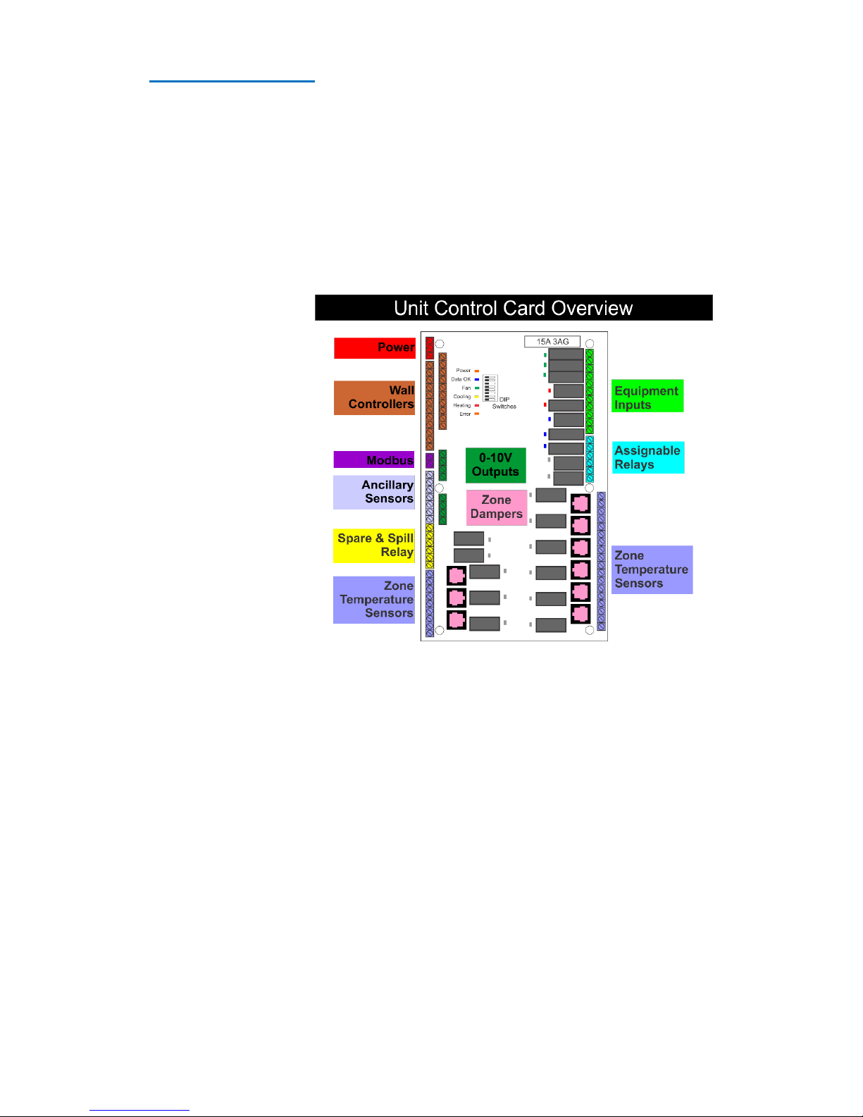
Unit Control Card
The HVAC unit control card is
the hub of the Falcon
system. All major
components of the Falcon
system connect here
including the HVAC system
itself. Information on
specific wiring the Falcon
HVAC unit control card to air
conditioning systems can be
found on page 21 of this
manual.
The HVAC unit control card is
powered by 24VAC requiring
a minimum of 1.5 amp. This
can be supplied by a
separate power adapter
(such as the Smart Temp SZ-PS power supply), the HVAC system itself or any other suitable 24VAC supply
that is capable of supplying at least 1.5 amp.
Page 19

Page 19
DIP Switch Settings
There are 8 DIP switches on the Falcon HVAC board. The first three are used for setting the function of
the Falcon to match the type of equipment under the Falcons control.
These settings must be done before power up. If these switch settings are changed after power up, you
must press the power cycle the HVAC board.
Falcon UCC connections
Terminal
Function
24V
24V AC input – Used to Power the Falcon HVAC card and wall controllers
0v
24V Ac input common.
Main Relay Common
(fused 15A)
Voltage applied here is switched back through equipment relays.
Consider this a standard thermostat “R” Terminal
G1
Low fan speed (Used in single fan speed mode)
G2
Medium fan speed (NOT used in single fan speed mode)
G3
High fan speed (NOT used in single fan speed mode)
W1 (NO)
Heat or Reversing valve terminal. - Heat valve drive open
W1 (NC)
Heat valve drive closed
W2 /Aux
Aux / Emergency heat.
Y1 (NO)
Compressor 1 or cooling terminal. - Cool valve drive open
Y1 (NC)
Cool valve drive closed
Y2
Compressor 2 or cooling 2 terminal
Y3
Compressor 3 or cooling 3 terminal
Assignable Relay 1 (NO)
Relay has a library of functions. Normally open terminal
Assignable Relay 1 (NC)
Relay has a library of functions. Normally closed terminal
Assignable relay 1
common
Voltage applied here is switch through relay 2 output
Assignable Relay 2 (NO)
Relay has a library of functions. Normally open terminal
Assignable Relay 2 (NC)
Relay has a library of functions. Normally closed terminal
Assignable relay 2
common
Voltage applied here is switch through relay 2 output
Sensor 1 Active
Outside air temperature sensor terminal active
Sensor 1 Common
Outside air temperature sensor terminal common
Sensor 2 Active
Indoor fan coil temperature sensor terminal active
Sensor 2 Common
Indoor fan coil temperature sensor terminal common
Sensor 3 Active
Assignable sensor input active
Sensor 3 Common
Assignable sensor input common
Analogue output 1 Active
Used as a output for digital scroll capacity control
Analogue output 1
Common
Analogue output common
Analogue output 2 Active
Assignable analogue output
Analogue output 2
Common
Analogue output common
Analogue output 3 Active
Assignable analogue output
Analogue output 3
Common
Analogue output common`
Wall Controller 1
Master / Primary wall controller connection
Wall Controller 2
First slave wall controller connection
Wall Controller 3
Second slave wall controller connection
Wall Controller 4
Third slave wall controller connection
Modbus A
Modbus Communications Terminal A
Modbus B
Modbus Communications Terminal B
Room sensors Active (9)
Room sensors Active terminal
Room sensors Common (9)
Room sensors Common terminal
Damper Drive Open (10)
Damper drive open terminals - 24VAC when dampers are open
Damper Drive Closed (10)
Damper drive closed terminals - 24VAC when dampers are closed
Damper Common (10)
Damper 24VAC common
Page 20

Page 20 DRAFT
Switch
Off
On
Sw 1 – Fan Speeds
1 Single speed fan
3 speed fan
Sw2 – System
Heat Cool Mode
Heat Pump mode
Sw3 – Reversing Valve (If Sw 2= ON)
Energise in Cool (O)
Energise in Heat (W)
Sw3 – Fan with Heat (If Sw 2= OFF)
Fan controlled by heater (HG)
Fan controlled by Falcon (HE)
Switch 4 to 8 should be left off – these have reserved functions.
Switch 1 sets the number of fan speeds for the indoor fan. If set for single fan speed only G1 (low) fan
output is used.
Switch 2 sets the control method.
In HP mode the Falcon will cycle the Equipment on or off in heating or cooling using the “Y” relay
outputs. The W1/OB outputs sets heating or cooling mode and does not normally change status unless
the opposite mode is called or after 2 hours – whatever occurs first. In HP mode it is normal to have both
“Y” & “W” on at the same time.
In HC mode the “Y” output(s) just controls cooling, the “W(/OB)” output(s) just control heating.
In HC mode you will never have “Y” & “W” on at the same time.
Switch 3 sets either the fan mode or reversing valve logic based on the position of switch 2. If switch 2 is
off (heat cool system under Falcon control) then switch 3 sets whether the Falcon calls for the indoor fan
in heat. (Sw 3 off – HG mode – Falcon lets the Gas Heater (HG) call its own fan. Switch 3 on – HE mode,
Falcon will call for the fan to start when electric heating (HE) starts.
If switch 2 is on, then switch 3 sets reversing valve mode. Energise the reversing valve in Cool mode (Sw
3= OFF) or energise the reversing valve in heat mode (Sw 3= On)
Relays
The Relays on the HVAC card are rated at 240v @ 10A maximum each. All equipment relays run through
a 15A 3AG fast blow glass fuse. The assignable relays rely on external fusing for protection.
Temperature Sensor
The Falcon sensors are 10K NTC type to. The Falcon is compatible with all of Smart Temps range of
temperature sensors.
0-10v Output.
The Falcon HVAC card has three 0-10v analogue outputs. AO 1 is assigned as capacity control output for
digital scroll air conditioners. AO2 & AO 3 have installer assignable functions.
The Falcon HVAC card has a number of Inputs and outputs. A table outlining these functions is provided
below.
Page 21
Page 21
Wiring Examples
The top Right corner of the UCC you will find the
terminals that will permit the control a typical
analogue “RYWG” system.
The DIP switch (Page 20) will configure the way these
relays operate. Alternatively, the Falcon also offers
0-10V outputs for controlling modulating heating and
cooling vales, as well as for other functions.
Several examples of wiring various systems are
provided below.
Please note, Not all possible wiring examples can be
provided here. For example, If you have a 3 fan speed
2 Stage Heat Pump System you may use the single
stage Heat Pump drawing and just add the
compressor output for the second stage.
Page 22

Page 22 DRAFT
Controlling Digital Inverter Systems
The Falcon, via a model specific adapter can control
various Digital Inverter Systems. This includes changing
modes and capacity output if permitted by the system.
When ordering the Inverter Adaptor, we must know the
brand on model number of the system you wish to control.
The Falcon if fitted with a Modbus Port that is used to
connect to the Inverter Adapter.
Each Inverter Adapter module is supplied with a custom
cable and detailed instructions on setting the adapter up
to the specific air conditioning system requirements.
Simply connect the Falcon Modbus “A” & “B” terminals to
the Inverter Adapter “A” & “B” terminals and plug the
custom cable supplied with the adapter into the Air
Conditioner wall controller input. These cable and
connections vary brand by brand, so it is important to
follow the specific instructions supplied with the Inverter
Adapter.
Not all functions supported by one brand of air
conditioner may be supported by other brands. This
is not a limitation of the Falcon Controller.
Please discuss your needs with Smart Temp or an
authorised distributor should you have questions.
Page 23

Page 23
Wall Controller Connections
The Falcon wall controller(s) are the user interface for the Falcon system. The wall controller is a backlit
5” colour touch screen with temperature, humidity and light sensors. Up to 4 wall controllers can be
installed on any one Falcon system and changes made on any one wall controller will be automatically
updated to the others.
The wall controller connects to the HVAC unit control card via either 4 or 6 wires (the last or only wall
controller uses 4 wires; all other previous wall controllers requires 5 wires. A single HVAC card and a single
wall controller requires only 4 wires) with a maximum recommended length of 30 meters.
Screened cable of 0.25 mm per conductor is recommended especially for long runs or when the runs may
be in noisy environments.
The wall controller connected to wall controller
input 1 is the “Master Wall Controller” and is the
only wall controller that will permit you to make
system adjustments in the Installer Menu. Taping
the info icon will provide identity information on
the wall controller.
On the back of the wall controller is a hardware switch
labelled “Master” or “Slave”. This switch should be set to
master if the wall controller is wired to Wall Controller 1 location on the Unit Control Card. If multiple wall
controllers are used and this wall controller is not in wall controller 1 location, it should be set to “Slave”
A table of the wiring required for single and multiple wall controller systems is provided.
Wall controllers Wiring
Falcon System with 1 Wall Controller
Wall Controller
Number
Wall Controller Terminals
Unit Control Card
Terminals
Wall Controller
Switch
Wall Control 1
1 2 5 6
1 2 5 6
Master
Falcon System with 2 Wall Controllers
Wall Controller
Number
Wall Controller Terminals
Unit Control Card
Terminals
Wall Controller
Switch
Wall Control 1
1 2 3 4 5 6
1 2 3 4 5 6
Master
Wall Control 2
1 2 5 6
1 2 5 6
Slave
Falcon System with 3 Wall Controllers
Wall Controller
Number
Wall Controller Terminals
Unit Control Card
Terminals
Wall Controller
Switch
Wall Control 1
1 2 3 4 5 6
1 2 3 4 5 6
Master
Page 24
Page 24 DRAFT
Zoning
Zone control can vastly improve user comfort by ensuring only areas of the home or office that require
heating or cooling are heated or cooled. Zones that are unoccupied or those that enjoy natural heating
from the sun or cooling in shade receive less conditioned air. This reduces energy costs and has the added
advantage of requiring a smaller AC system to be required.
Although only a small section in this manual discusses the Falcon Zone control, zone control is a significant
part of the Falcon system. If using the Falcon for zoning and you wish to get the best performance from
the Falcon, the zones under the Falcon control and the HVAC system connected to the Falcon it is
important that you understand the straightforward way the Falcon operates when controlling zones.
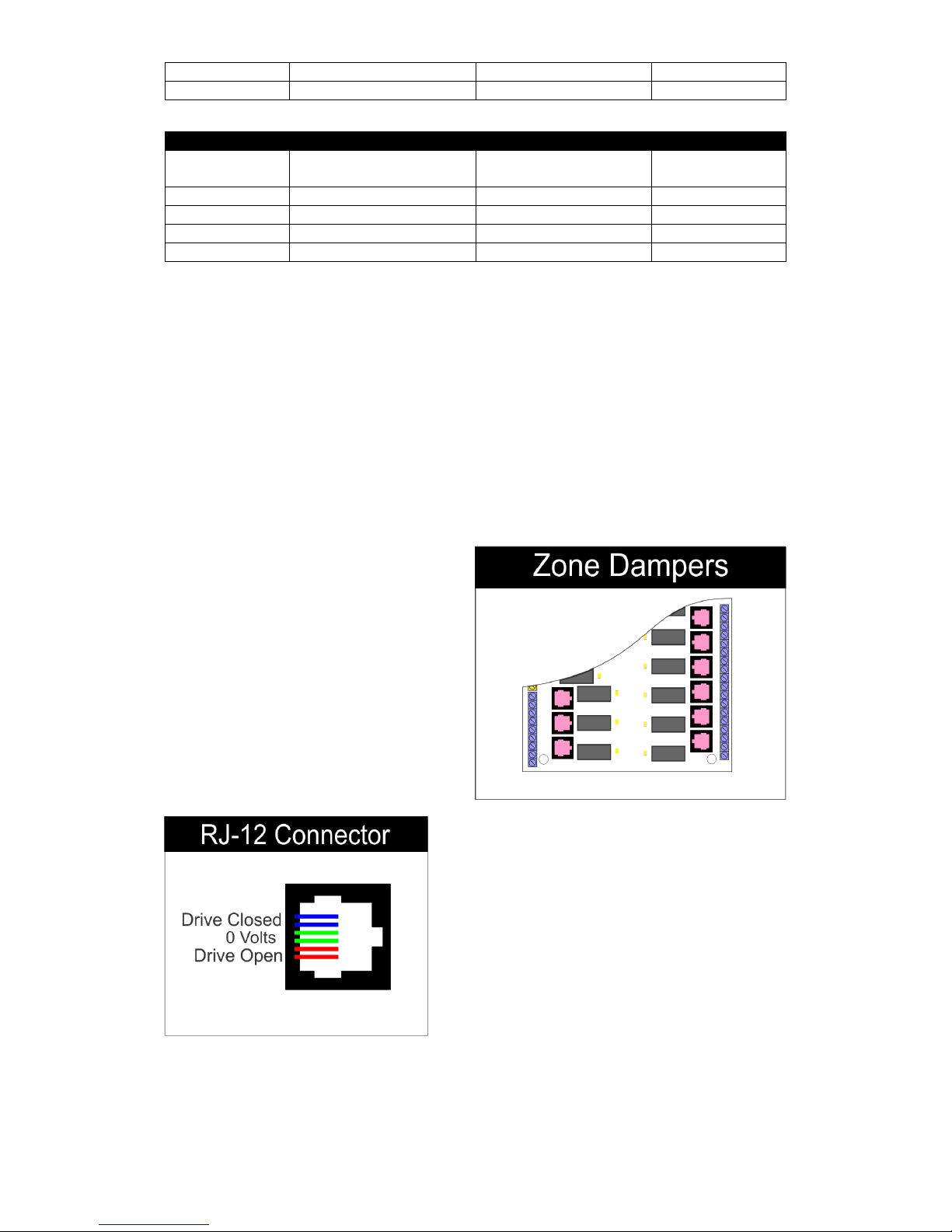
Zone Wiring.
The Falcon system will only accept 24V Drive Open
and/or Drive Closed actuators connected to the
UCC RJ-12 interface (0-10V actuators are
independently supplied so can be any voltage)
All zone motors are wired directly to the Falcon
Unit Control Card as shown to the right. Drive
open/closed motors are powered by the Unit
Control card 24VAC input. (Ensure the power
supply used to power your Falcon has enough
power to also power the 24V dampers.)
Standard Drive Open / Drive Closed are connected to the
Falcon UCC using the RJ12 terminals shown in pink above.
There are 6 PINS inside the RJ12-connector, the two centre
pins are 0V, the two on either side are Drive open and drive
closed as shown by the drawing to the right.
When using modulating (0-10v dampers) simply wire the
damper to the zone terminal 0 and 10V.
For those that have or wish to use wired dampers (that
don’t use the RJ12 connectors but have 3 terminals) Smart Temp provide adapters. Pn SZ-RJTB.
Understanding the Zone Settings
Should you wish to enable it, the Falcon has intelligent zone management logic will ensure the zone
control operates in such a way to meet the expectations of the user while maintaining the demands of
Wall Control 2
1 2 3 4 5 6
1 2 3 4 5 6
Slave
Wall Control 3
1 2 5 6
1 2 5 6
Slave
Falcon System with 4 Wall Controllers
Wall Controller
Number
Wall Controller Terminals
Unit Control Card
Terminals
Wall Controller
Switch
Wall Control 1
1 2 3 4 5 6
1 2 3 4 5 6
Master
Wall Control 2
1 2 3 4 5 6
1 2 3 4 5 6
Slave
Wall Control 3
1 2 3 4 5 6
1 2 3 4 5 6
Slave
Wall Control 4
1 2 5 6
1 2 5 6
Slave
Page 25
Page 25
the AC equipment under the Falcon control. These settings are optional but if set correctly they can
significantly improve the Falcon zoning performance.
Fixed capacity AC systems especially require a minimum amount of air flow through them to run
effectively, without this minimum flow requirements being met the efficiency (and health) of the AC
system may suffer. The Falcon zone control system must know when it’s safe to run the heating or cooling
systems and when unsafe. The Falcon ideally also needs to know if there is too much demand for the
available capacity of the HVAC system.
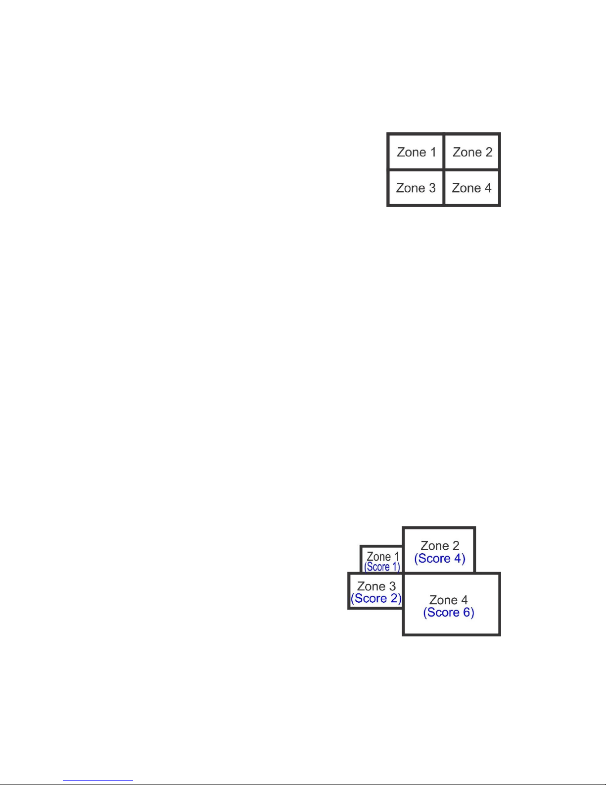
For Example, a hypothetical building has 4 zones that requires heating.
Each zone is an identical size and each zone has identical demands. The
fixed capacity AC system controlling these 4 zones has too much capacity
to run just one zone alone, one zone alone calling heating will restrict air
flow through the AC system to much potentially causing damage to the ducts or to the AC system itself.
Two zones calling is ok, but not ideal. Any 3 zones calling is perfect however when all 4 zones are calling
the AC system heating at the same time the AC system struggles and can’t meet the total demand for
heating, so all 4 zones suffer.
The Falcon zone settings menu permits the installer to define the minimum and maximum capacity of the
AC system for heating and cooling and apply that to when zones can be heated (or cooled).
By using the Falcon zone control settings in the above example, the Falcon will not run heating if any one
zone calls; it will wait for more than 1 zone to call before staring the AC system in heating mode. When 2
zones call the Falcon will start the system in heating mode but can restrict fan speed to low (when AC
systems with 3 fan speeds are used) or additionally open a “spill” or “relief” damper to move excess
capacity to a communal area thereby easing the load on the AC system. If any 3 zones call the Falcon will
close the “spill” or “relief” damper and permit higher fan speeds to operate. If 4 zones are called, the
Falcon will intelligently select the 3 most important zones and use the AC system to heat those, when one
of those 3 reach temperature the Falcon will then heat the last zone. When only one zone remains needing
heating (hopefully not too much now) the Falcon will shut the AC system down to protect it.
In the real world not all zones are created equal and not all zones have an identical demand as shown in
the example to the right. In this case zone 4 if called alone is ok, as is zone 2, but zone 1 and 3 are both
too small to run alone or even together if both zones demand heating as their combined size is still below
the safe value to run the AC system in heating mode.
The Falcon overcomes these issues by using an easy to
understand “scoring” system. The Falcon zone scoring system
is relative to the building and not based on a fixed score that is
directly proportional to M3 of zone size.
Simply put - the bigger the zone in the building relative to all
the others zones in the building, the higher the “score” you
give that zone.
Page 26

Page 26 DRAFT
The Falcon permits you to assigning a zone size from 1 (very small zone) to 6 (very large zone) for each
zone in the Zone Setup window, plus set a zone priority from low too high for each zone. Further the
Falcon permits you to give the AC system a minimum and maximum heating and cooling demand “score”
as well as high fan speeds and spill or
bypass damper a “scores”. The zone
“score” works with the equipment demand
“scores”
In this example, zone 4 being the largest
would get a score of 6. Zone 1 the smallest
zone would get a score of 1. Zone 3 would
get a score of 2 and zone 2 a score of 4 for
example.
In the equipment setup for zoning (shown
right) we could then give the minimum heating demand “score” a value of 4, meaning that the sum of the
individual zones “score” calling for heat must exceed 4 before the AC system is permitted to start heating.
We can also set a maximum heating score of 7 should we wish so that if the sum of the “scores” from all
of the calling zones exceed 7 the Falcon will close down zones based on the zone priority as set in the
installer Zone Setup menu. Fan speeds and spill dampers are also able to have a “score” assigned to them
to determine when and how they function.
Zone scoring is optional, if you wish the factory default settings can be left unchanged and the Falcon will
heat and cool all zones as each zone demands heating and cooling without restriction. The Falcon can be
as powerful with its zone control options as you wish, or left as a basic zone control.
Zone Control Methods
To further tune your Falcon zoning
capability many user zone control methods
are provided.
Basic Control Method (Open / Close damper
logic)
Basic control method is the most user
restrictive method and is intended for use in
commercial buildings where changes to
system function and performance is not permitted. In basic mode all zones are on (zones cannot be turned
off) and all zones will maintain the same set point. IE. An office building with 5 offices being serviced by 1
air conditioner and all offices are to maintain 22.c
Normal Control Method (Open / Close damper logic)
Normal mode is similar to basic mode as described above insomuch that all zones maintain the same set
point however in normal mode you are permitted to close some zones off. IE an office building with 5
offices all serviced by one air conditioner however at times some offices are empty.
Advanced Control Method (Open / Close damper logic)
Advanced control method offers the greatest control flexibility. It permits the user to have individual
scheduling as well as individual heating and cooling set points in every zone. Adjust zone temperatures
and schedules just as if every zone had its own dedicated HVAC system.
Variable Control Method (0-10v damper control)
Variable zone control offers the same user function as does advanced control however the Falcon will
modulate dampers open and closed and provide a 0-10V control signal to the variable capacity capable
Page 27

Page 27
HVAC system to vary the HVAC system output capacity. As zones, open and close based on demand the
HVAC system will increase or decrease its output to match.
As with the advanced zone control method described above, each zone can be set individually from other
zones.
The 24VAC voltage is switch from the Falcon relays to drive zone motors. Please take the zone motor
current requirements into account when sizing the power requirements for the Falcon zone card. 2A is
recommended.
Zone Temperature Sensors
The Falcon sensors are 10K NTC type to. The Falcon is compatible with all of Smart Temps range of
temperature sensors.
Zone sensors are optional in zoning however if a sensor is not installer the Falcon will be unable to control
the zone temperature.
The Falcon Zone card is fitted with both terminals and a RJ-12 socket for drive open / drive closed dampers
- either can be used.
The Falcon will control 240v modulating actuators if necessary, simply replace the 24V power supply for
240V in the above example.
Ancillary Devices
Smart Temp also offer a number of additional optional components for your Falcon.
Power supply. 24V @ 2 amp power supply. Enough to power both your Falcon HVAC and zones cards.
(part number SZ-PS)
RJ-24 Cables. The Falcon uses standard “LAN” type RJ24patch leads to connect the Falcon wall
controller and zone card to the HVAC unit control card. These can be supplied in a range of lengths.
Room Sensors. When measuring zone temperatures the optional zone sensor is required. It is a two
wire, non-polarity dependent sensor that connects to the Falcon zone card temperature input terminal.
(Part number RS-1)
RS-12 Cables. The Falcon zone card is fitted with both terminal strips and RJ-12 connectors for zone
damper wiring. Some find this method of wiring the zone dampers more convenient and less prone to
error. The cables come in 15 meter lengths. (Part Number SZ-RJ12-15)
Page 28

Page 28 DRAFT
Installer menu
The Falcon installer menu is protected by a Security PIN with the aim of limiting access to the Falcon
installer settings by any un-authorised (or uninformed) people. This PIN can be changed if desired
however changing the PIN and then forgetting the new PIN will require the Falcon wall controller to be
returned to Smart Temp or an authorised service person for unlocking. There may be a fee for this service.
To enter the Falcon installer menu, tap the installer Icon and on the PIN prompt screen that
appears enter the PIN and then press next. If the PIN is correct you will enter the installer options
menu. If the PIN is incorrect you will be exited from the installer menu.
The Falcon default unlock pin is 0101 (Zero One Zero One)
When in the installer menu, you will be
presented with many tabbed pages (Tabs are
shown at the bottom of the page). On each
page there are a list of options that can be
selected. The option name is shown to the left
and the current value for the option shown to
its right.
To change a value simply tap the option value
you wish to change, it will highlight Yellow to
show it has been selected Lockout Heating Above in the above example). Use the up/down button to
scroll through the options or values available for that option selected. Press “DONE” to save the change.
Please Note - the Falcon options pages are dynamic. Options will vary based on the Falcon HVAC card DIP
switch settings as well as other settings within the Falcon System.
The pages and options on each page are listed below.
Equip(ment) Tab (HP Mode Sw 2 =On)
Value
Option
Comp 1
Span comp 1 Set in 0.1 steps 0.5 to 3c (displayed in local format C/F)
Comp 2
Span comp 2 Set in 0.1 steps Off to 3c (displayed in local format C/F)
Comp 3
Span comp 3 Set in 0.1 steps Off to 3c (displayed in local format C/F)
Heat 1
Reversing Valve (Display only – set by DIP 3)
Heat 2
Stage 2 Heat Span Set in 0.1 steps 0.5 to 3c (displayed in local
format C/F)
E-heat fitted
Emergency Heat fitted Yes/No
Use Aux heat Below
Requires outside air sensor – Disable comp and use Aux Heat below this
value
Use Aux heat after
Fan with Aux Heat
Comp with Aux Heat
Stage Fan Speed
Smart Fan
Tick to enable Smart Fan function (Commercial Programmable indoor fan)
Equip(ment) Tab (HC Mode Sw 2 =On)
Value
Option
Stage 1 Cool
Span comp 1 Set in 0.1 steps 0.5 to 3c (displayed in local format C/F)
Stage 2 Cool
Span comp 2 Set in 0.1 steps Off to 3c (displayed in local format C/F)
Stage 3 Cool
Span comp 3 Set in 0.1 steps Off to 3c (displayed in local format C/F)
Stage 1 Heat
Reversing Valve (Display only – set by DIP 3)
Page 29

Page 29
Stage 2 Heat
Stage 2 Heat Span Set in 0.1 steps 0.5 to 3c (displayed in local
format C/F)
Fan with Heat
Indoor fan mode in heat (Display only – set by DIP 3)
Stage Fan Speed
Smart Fan
Tick to enable Smart Fan function (Commercial Programmable indoor fan)
Limits Tab
Value
Option
Max Heating Set Temp
This is the maximum heating set temperature the user is permitted to select
Min Cooling Set Temp
This is the Minimum cooling set temperature the user is permitted to select
Lockout Heating Above
Heating will be disabled when outside temperature exceeds this
temperature
Lockout Cooling Below
Cooling will be disabled when outside temperature is below this
temperature
Lockout Stage 2+ heat
Above
Stage 2 and higher heating will be disabled when outside temperature
exceeds this value. Stage 1 heating will still function
Lockout Stage 2+ Cool
Below
Stage 2 and higher cooling will be disabled when outside temperature falls
below this value. Stage 1 cooling will still function
Safety Tab
Value
Option
Anti-cycle Delay
(All Compressors)
Compressor anti cycle delay timer. (minimum compressor off time before
any restart)
Minimum Run Time
Once a compressor starts, it will run for this minimum period before
stopping, regardless of any other value.
Fan Purge
Indoor fan will continue to run past heating / cooling stops if fan mode auto.
Warm Start
Will wait for indoor coil to warm before staring indoor fan in heating
Coil Temperature
Coil temperature before indoor fan starts
Heat Overshoot
Heating will continue to run until this value above user set point
Cool Overshoot
Cooling will continue to run until this value below cooling set point
Damper Delay
Time it takes for the zone damper to fully open from completely closed.
Dead band
The minimum distance permitted between users heating and cooling set
points
Zone Tab
See “Setting up Zoning” on page 14 for information on the settings within this tab
Value
Option
Number of Zones
Enables zoning function and sets number of zones – Requires Zone
hardware.
Zone Control Method
Select Basic, Normal, Advanced or Variable zone control logic.
Duct Pressure Sensor
Sets the Threshold (input voltage on zone card pressure input) that opens
all dampers if ducts over pressurise
Limit fan to low Speed
Sets the “zone score” to limit fan speed to low
Min Heating Call
Sets the minimum “zone score” to enable heating
Min Cooling Call
Sets the minimum “zone score” to enable cooling
Max Heating Call
Sets the maximum “zone score” for heating capacity
Max Cooling Call
Sets the maximum “zone score” for cooling capacity
Min Damper Position
Sets the maximum damper position for 0-10V damper ( Variable mode only)
Max Damper position
Sets the minimum damper position for 0-10V damper ( Variable mode only)
Permitted Overrun
Sets the amount of “extra” capacity over equipment rated value.
( Variable mode only)
Equipment Capacity
Sets the equipment capacity. (Variable mode only)
Zone Setup Button
Press to setup individual zone settings
Page 30

Page 30 DRAFT
Zone Setup Button
Value
Option
Zone name
Enter the name of the zone using the Keyboard. Upper/ lower case can be
sued as well as numerals and other characters
Zone Control Method
Select zone control Method as described on page 26 of this manual
Zone Sensor
Select the temperature sensor used for this zone (if any)
Zone Size
Select the relative size of the zone when compared to other zones in the
system
Zone priority
Set the zone priority when compared to other zones in the system
Minimum Damper
If using 0-10V dampers set the minimum closed damper position when the
zone does not require heating or cooling
Maximum Damper
If using 0-10V dampers set the Maximum damper open position when the
zone is being heated or cooled
Zone run alone
Check this box if you wish this zone to be able to run without the normal
minimum score rules being met.
Advanced Tab
Value
Option
Economy Cooling
If enabled, an assignable relay can be used to draw in cool outside when
suitable to cool the building. This replaces first stage cooling only.
Economy Temp
The economy cooling set temperature to use.
Economy Span
The difference between economy cooling on and off points.
Economy Comp
Select Compressor run status during economy cooling
Humidifier
If enabled, an assignable relay can be used to change state at the RH set
value
Humidly Settings
RH threshold for assignable relay function
Filter Reminder
Enable / disable filter clean warning and set period.
Display C/F
Falcon display units
Aux Relay 1
Assignable relay 1 function
Aux Relay 2
Assignable relay 2 function
0-10v 1
Assignable 0-10V 1 Function – Typically used for digital scroll capacity
control.
0-10V 2
Assignable 0-10V 2 Function
O-10V 3
Assignable 0-10V 3 Function
0-10V Heat Span
Sets the range of the assignable 0-10V output when used for heating valve
control
0-10V Cool Span
Sets the range of the assignable 0-10V output when used for cooling valve
control
Event Tab
Value
Option
System Daily Events
Set number of daily events (active in programmable mode only)
Event 1 Name
Set event 1 name with keyboard
Event 2 Name
Set event 2 name with keyboard
Event 3 Name
Set event 3 name with keyboard
Event 4 Name
Set event 4 name with keyboard
Event 5 Name
Set event 5 name with keyboard
Event 6 Name
Set event 6 name with keyboard
PIN Tab
Value
Option
Change PIN
Enter a new pin, then re-enter to confirm PIN. Sets new installer PIN
Page 31

Page 31
Reset Tab
Value
Option
Reset To factory
Resets Falcon to factory settings - NOTE - critical equipment control
parameters are set via mechanical hardware switches. These values are NOT
reset.
SD Card Tab
Value
Option
Copy wall paper
Upload custom wall paper into Falcon from SD card. Note - Must be JPG files
and formatted 800 x 480 in size.
Wall paper must be loaded in the directory /Falcon/wallpaper
Upgrade Firmware
Upload new firmware from SD card.
Note – firmware must be in the directory /Falcon/firmware
Details Tab
Value
Option
Company Name
Enter your company name as you wish it shown on the Falcon Home screen
Info/Contact page
Phone Number
Enter the phone number you wish shown on the Falcon Home screen
Info/Contact page
Web Address
Enter your company web page as you wish it shown on the Falcon Home
screen Info/Contact page
Email Address
Enter your email address as you wish it shown on the Falcon Home screen
Info/Contact page
Time lock Button
Sensor Tab
Value
Option
Fitted Sensor
calibration
Use this setting to calibrate the temperature sensor fitted to the Falcon
Touch screen – this setting is for a hardware calibration offset.
For zones fitted with temperature sensors other than the Falcon Touch
Screen, the two wire RS-1 for example please use the calibration offset
adjustment feature in the Zone setup window.
More Button
Value
Option
Move to next set of installer option screens
Back Button
Value
Option
Moves to previous set of installer option screens
Exit Button
Value
Option
Exits Installer Menu
 Loading...