

Page 1
TM
Super
Smart Temp
ERT
Manual
Congratulations on the purchase of your new Electronic Thermostat!
Your new Smart Temp ERT thermostat has been built using the best components and design
philosophy currently available. As a result, if properly installed your new electronic programmable
thermostat will provide you with many years of trouble free and reliable service.
Your Smart Temp ERT Thermostat has been designed to be an attractive, highly reliable and easy
to use thermostat. By taking the time to read and understand these simple instructions you can
take advantage of many of the capabilities that are offered in the ERT.
Overview
To assist in your understanding and use of the ERT, a brief description of
the functions and controls is given below. A more complete step-by-step
instruction on using the ERT is given later in the manual.
ON / OFF Button
To turn the ERT on, press the ON/OFF button, a small arrow mark will turn on next to
the word “ON” printed on the body of the thermostat. To turn the ERT off press and hold
the ON/OFF button until the arrow disappears. NOTE: If you continue to hold the
ON/OFF button for approximately 8 seconds the ERT will enter economy comfort mode
(described later in this manual)
Set Buttons
The set (or desired) room temperature can be adjusted by pressing the plus or minus
SET buttons on the face of the ERT Each press will increase or decrease the set
temperature by 1 deg C. The ERT is a single set point thermostat. For example, setting
the desired temperature at 21 deg C will bring on the AC heating if the room
temperature falls below 20 deg C and bring on the AC cooling if the room temperature
raises above 22 deg C.
Auto Fan Button
The ERT can control the system fan in two ways. Each press of the Auto Fan button
alternates the ERT between Auto fan mode or continuous (Occupied) fan mode.
Auto Fan Mode - The fan will run only while the AC system is heating or
cooling. When the need for heating or cooling stops, so does the fan. Auto
Fan mode active is indicated by an arrow symbol pointing to the A.fan text
printed on the thermostat body
Continuous Fan Mode (Occupied Fan). - In this mode, the fan will turn on
when the ERT is on and remain on until the ERT is turned off. The fan will
remain on during this time regardless of whether there is a need to bring on
the AC system heating or cooling. This mode is used to improve building
ventilation.
Mode Button
The MODE button cycles the ERT through Heat only, Cool Only, Auto-Change over or
Fan only operational modes. These modes are detailed below.
Heat only mode The ERT will turn on the AC Heating when the room
temperature falls below the set temperature. In Heat only mode the ERT will
not bring on the AC Cooling regardless of the room and Set Temperature. In
Heat only mode the arrow symbol will point to the word “HEAT” printed on the
thermostat body.
Cool only mode - The ERT will turn on the AC Cooling when the room
temperature raises above the set temperature. In Cool only mode the ERT will
not bring on the AC Heating regardless of the room and Set Temperature. In
Cool only mode the arrow symbol will point to the word “COOL ” printed on
the thermostat body.
Auto-change over mode - The ISIS will turn on the AC Heating if the room
temperature falls below the SET temperature and the AC Cooling if the room
temperature rises above the SET temperature. Auto changeover mode is
indicated by words, “HEAT” & “COOL” in the LCD.
Fan Only mode. In Fan only mode the ERT will turn on the system fan for
continuous operation. The ERT will not control the AC heating or cooling
system regardless of the room and set temperature. I
F/C Button
The ERT will display the room and set temperature in ether Deg C or Deg F. Pressing
the F/C button will toggle between these two display options.
Advanced Functions
EC or Economy Comfort Mode
Your ERT thermostat is fitted with a unique
Economy Comfort or Un-occupied mode.
The EC mode sets the thermostat mode to Auto changeover
mode and limits fan mode to Auto fan mode. In EC mode the thermostat will activate
system heating when the room falls below the EC heat Temperature and system
cooling when the room temperature is above the EC cooling temperature.
The EC mode is ideal for situations where you do not with the building to overheat or
freeze during holidays or long periods of in attendance.
To activate EC mode simply press and hold the On/Off button for 5 seconds. The
letters “EC” will be displayed on the thermostat to confirm this mode is active.
To turn off the EC mode simply press and hold the On/Off button for 5 seconds. The
thermostat display will return to normal.
The EC temperature set points can be adjusted by entering the service mode as
detailed later in this manual.
The factory default value for the EC mode is Heat Temp to 10degC and cooling temp
to 35 deg C.
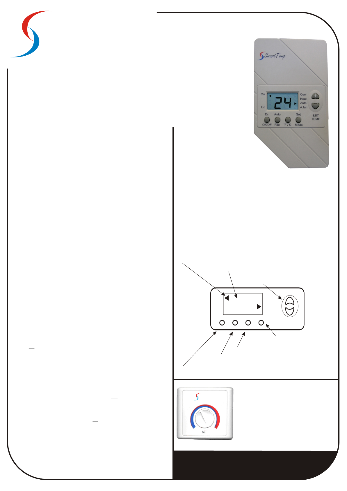
Arrows indicate active modes
Displays Room & Set Temp
On
Ec
Used to turn the thermostat On & Off
Used to activate Ecconomy Comfort Mode
Smart Temp
Pict 1
21
Auto
Ec
On/Off
Fan
Sets display to Deg C or Deg F
Toggels Fan mode between Auto Fan or
Continuous Fan modes
For security and convenience the ERT may be
installed in a more remote or secure location. In
such applications the ERT will measure the
temperature in the room to be controlled via a
remotely connected temperature sensor(s).
Pict 1 shows the Smart Temp adjustable version of
this sensor.
It is important that consideration is given to this
sensor as placing hot items (such as kettles or
urns) or cold items (such as chest freezers) under
or in the vicinity of these sensors could result in
uncomfortable room temperatures.
Used to adjust set temperature
Cool
Heat
Auto
A.Fan
Set
Mode
F/C
+
-
SET
TEMP
Used to select thermostats
mode (Heat / Cool / Auto etc)
Making Life ComfortableMaking Life Comfortable
Page 2
Installing the thermostat
Service Mode
Service mode is used to activate advanced installer functions. By entering this mode
it is essential that an understanding of AC functions and their consequences are
understood or inaccurate or incorrect system performance can be expected.
If you are unsure about the settings in this mode it is recommended that you contact
To enter Service Mode:
Make sure JP 2 is ON and the correct mode jumpers are set before proceeding.
Power up the thermostat
Set the room temperature to 10 Deg C.
Press and hold the Mode button for 5 seconds. An arrow at EC & Cool will activate
indicating this is the cool set point for EC mode - The temperature the ERT thermostat
will cool to when EC mode is active. Adjust this value with the temp + & - buttons.
Default value is 30 Deg C.
Press the mode button again. An arrow at EC & Heat will activate indicating this is
the heat set point for EC mode - The temperature the ERT thermostat will Heat to
when EC mode is active. Adjust this value with the temp + & - buttons. Default value
is 10 Deg C.
Press the mode button again. An arrow at Cool will activate indicating this is the
minimum permissible temperature the thermostat can be adjusted to during normal
operation. (Used to prevent the thermostat being set to unrealistic cooling
temperatures) Adjust this value with the temp + & - buttons. Default value is 10 deg C.
Press the mode button again. An arrow at Heat will activate indicating this is the
maximum permissible temperature the thermostat can be adjusted to during normal
operation. (Used to prevent the thermostat being set to unrealistic heating
temperatures) Adjust this value with the temp + & - buttons. Default value is 30 deg C.
Press the mode button again to set Reversing Valve modes or Fan control modes.
If the ERT is set to a Heat Pump Mode “HC” will be displayed with either “H” or “C”
flashing (selected). Select reversing valve to be energised in “H” (Heat) or “C” (Cool)
mode with the temp + & - buttons.
If the ERT is set to a Heat / Cool mode (No Control) “EO” will be displayed with either
“E” or “O” flashing (selected). This determines the correct method to control the fan in
heat mode - In “E” (Electric) the thermostat will energise the “G” (fan) terminal to
active the fan or “O” (oil or gas - plenum switch) will permit the heating equipment to
control its own fan. Select the correct mode with the temp + & - buttons.
Press the mode button again to return the ETN to normal mode.
Adjust the set temperature to a value more comfortable than 10 deg C.
If necessary remove JP2 (compressor protection delay)
Smart Temp for clarification before any adjustments are made.
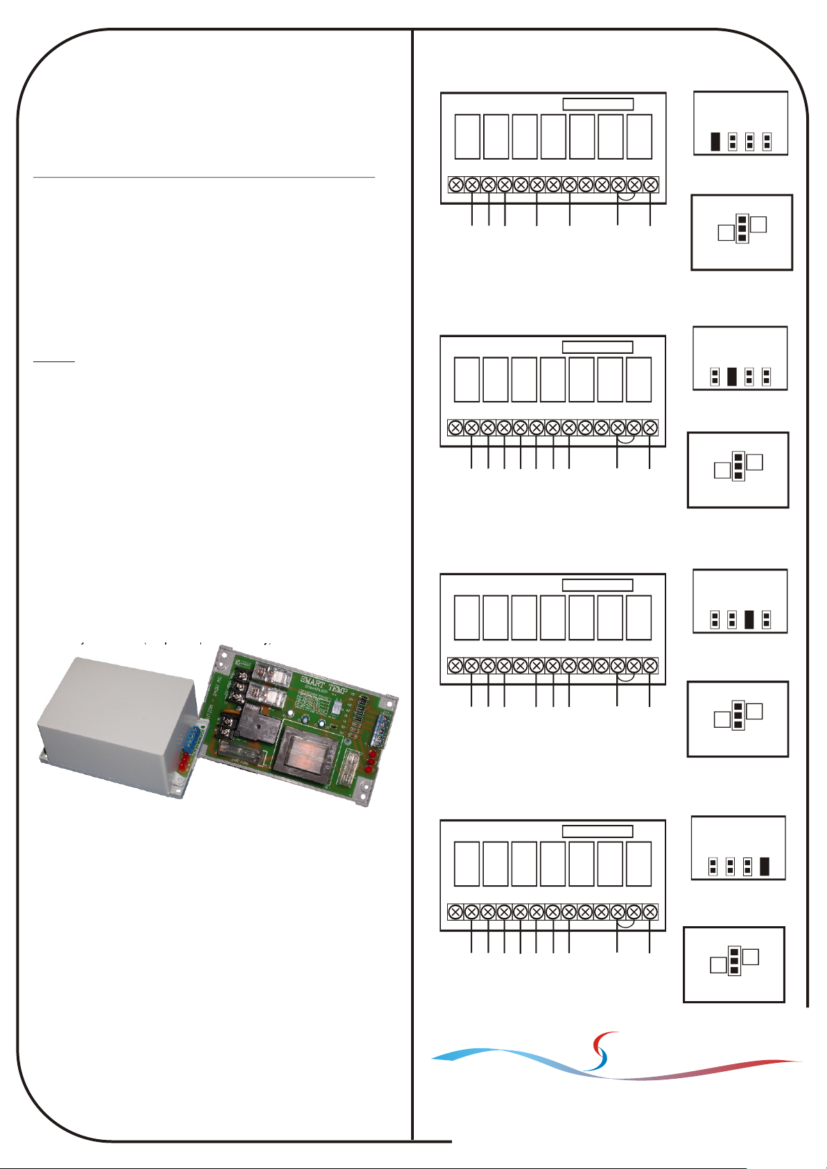
Wiring
1 Stage Heat 1 Stage Cool
Ribbon cable connector
Relay 1
Relay 2
Relay 3
Relay 4
Relay 5
Relay 6
Relay 7
N/A Y1 Y2 W1 W2 G1 AL AL Rc Rh CT T
Sensor
Remote
Cool
Optional
Fan
Heat
24 V Active
24 V Neutral
2 Stage Heat 2 Stage Cool
Ribbon cable connector
Relay 1
Relay 2
Relay 3
Relay 4
Relay 5
Relay 6
Relay 7
N/A Y1 Y2 W1 W2 G1 AL AL Rc Rh CT T
Sensor
Remote
Cool 1
Optional
Cool 2
Fan
Heat 1
Heat 2
24 V Active
24 V Neutral
1 Stage Heat Pump with Aux Heat
Ribbon cable connector
Relay 1
Relay 2
Relay 3
Relay 4
Relay 5
Relay 6
Relay 7
N/A Y1 Y2 W1 W2 G1 AL AL Rc Rh CT T
Sensor
Remote
Comp
Optional
Aux Heat
Fan
Rev Valve
24 V Active
24 V Neutral
Jumper Configuration
HC11
HC22
HP21
HP32
JP 2 On for Comp
3 min delay
Sensor
B
A
Position A = Internal
Position B = Remote
Jumper Configuration
HC11
HC22
HP21
HP32
JP 2 On for Comp
3 min delay
Sensor
B
A
Position A = Internal
Position B = Remote
Jumper Configuration
HC11
HC22
HP21
HP32
JP 2 On for Comp
3 min delay
Sensor
B
A
Position A = Internal
Position B = Remote
For 240 V appliations the optional Smart Pak is available
Specifications
Range: 5° to 30° c.
Resolution: 1.0°c
Accuracy: 0.3°c
Dead Band: 0.8°c
Stage Delay: 1.2° c
EC Settings: 10°c & 30°c
Load rating: 2Amps.
Voltage: 24VAC.
Connectors: Screw type.
Material: PC/ABS
Size: 80 x 140 x 33mm
Flamability: UL 94V-0
Weight: 145g
Warranty: 2 years
2 Stage Heat Pump with Aux Heat
Ribbon cable connector
Relay 1
Relay 2
Relay 3
Relay 4
Relay 5
Relay 6
Relay 7
N/A Y1 Y2 W1 W2 G1 AL AL Rc Rh CT T
Sensor
Remote
Aux Heat
Fan
Rev Valve
Comp 1
Optional
Comp 2
24 V Active
Smart Temp
19 Indra Road Blackburn South 3130
Phone:(03) 9899 6455 Fax (03) 9899 6454
www.thermostat.com.au
JP 2 On for Comp
24 V Neutral
Australia
Jumper Configuration
HC11
HC22
HP21
HP32
3 min delay
Sensor
B
A
Position A = Internal
Position B = Remote
Making Life Comfortable
 Loading...