

Page 1
Model 44-233
Smart Temp
o
c
TEMP
23
Your Smart Temp model 44-233 is a non programable thermostat
capable of controlling both Heating & Cooling systems. As this
thermostat is non programable it does not require a complicated set up
procedure. Simply select your required mode of operation and set your
desired temperature. The 44-233 will then control your Heating or
Cooling system to maintain your set temperature.
Please note: Even though this thermostat is capable of controlling both
a heating and a cooling system, you may not have a heating and a
cooling system installed in your home.
Selecting Mode
System
Cool Off Heat
Off
In this position your thermostat will not control your heating or cooling
system regardless of your set temperature and the room temperature.
Heat
When “HEAT” is selected your thermostat will turn on your home
heating system if your room temperature falls below your heating set
temperature. When your thermostat calls your heating system to
operate and supply warm air into your home, the word “HEAT” will be
shown in the LCD to confirm heating is required. If the word “HEAT”
flashes in the LCD there is a 4 minute system time delay in progress.
There is NO control of your cooling system in this mode.
Cool
When “Cool” is selected your thermostat will turn on your home cooling
system if your room temperature raises above your cooling set
temperature. When your thermostat calls your cooling system to
operate and supply cooled air into your home, the word “COOL” will be
shown in the LCD to confirm cooling is required. If the word “COOL”
flashes in the LCD there is a 4 minute system time delay in progress.
There is NO control of your heating system in this mode.
Fan
On Auto
Auto
In this position the fan will turn on and off when the heating or cooling
turns on and off. This is the recommended position for this switch.
On
In this position the Heating and Cooling systems fan will operate
continuously, 24 hours a day 7 days a week. This mode is ideal when
you wish to improve the ventilation in your home without changing
the temperature.
Your thermostat has 3 modes of operation as selected
by the “Mode” switch. These functions are described
below.
Selecting Fan Operation
Your thermostat can control your heating or cooling
system fan in two ways as described below.
F
Electronic Manual Thermostat
Your new Smart Temp thermostat
and design philosophy. As a result, if properly installed your new electronic
The Smart Temp 44-233 has been designed to be attractive, highly reliable
and simple to use. Please take the time to read these simple instruction to
Owners Manual
Congratulations on the purchase of your new Electronic
Thermostat!
has been built using the best components
programmable thermostat will provide you with years of trouble free and
familiarise yourself with the function and features offered in this product.
Setting your desired Temperature
To adjust your desired temperature first select the operational mode,
either heating or cooling.
Next, press and hold either the up button or the down button. The
LCD will show the words “SET TEMP” and either “HEAT” or “COOL”.
The set temperature will then start to move in the required direction.
When your desired temperature is shown in the LCD take you finger
from the button and the LCD will return to the normal display. Your
new set temperature is active.
If the thermostat is calling heating or cooling, the word HEAT or COOL
will be shown in the LCD to confirm this function is required.
LCD Back light
The LCD will illuminate when ever a button is pressed to assist with
the adjustment in poorly lit areas. The back light will stay on for 7
seconds after the last button has been pressed.
Low Battery Warning
Your thermostat operates on two ALKALINE “AA”
batteries. When these batteries are low the back
light function is suspended and the low battery
symbol flashes. Replace the batteries as soon as
possible. If no action to replace the batteries is taken within a few
days the thermostat will shut down until the batteries are replaced.
Filter Warning
The 44-233 records your heating and cooling usage. When the total
accumulated run time reached 400 hours the filter warning symbol
flashes to remind you to clean your return air filter if installed.
Press ands hold the filter button for 5 seconds to reset this counter.
Error Messages
If your thermostat displays E1, E2, Hi or Lo replace your batteries with
2 new “AA” Alkaline batteries even if you have just replaced them. If
the problem persists please call your installer or Smart Temp
Australia P/L
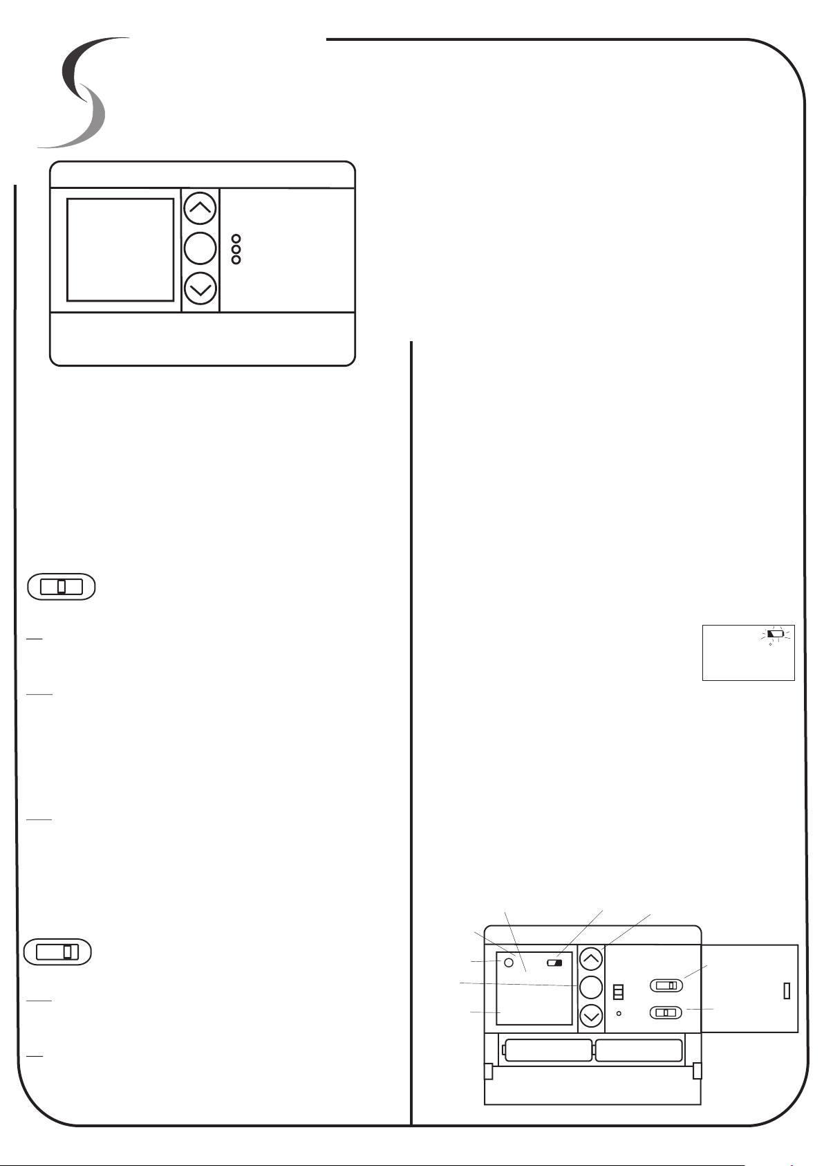
Room/Set Temp
Backlit LCD
Clean Filter
Warning
Filter
Counter / Reset
Mode
Indicator
SET
TEMP
HEAT COOL SPAN
Fig 2
reliable service.
Low Battery Warning
F FILTER
o
c
23
Battery compartment
2 x “AA” Alkaline only
Battery compartment door
F
Temperature
Adjust
Reset
Fan
On Auto
System
Cool Off Heat
TEMP
22
Fan Mode
Selector
System Mode
Selector
Function switch
door
C
Page 2
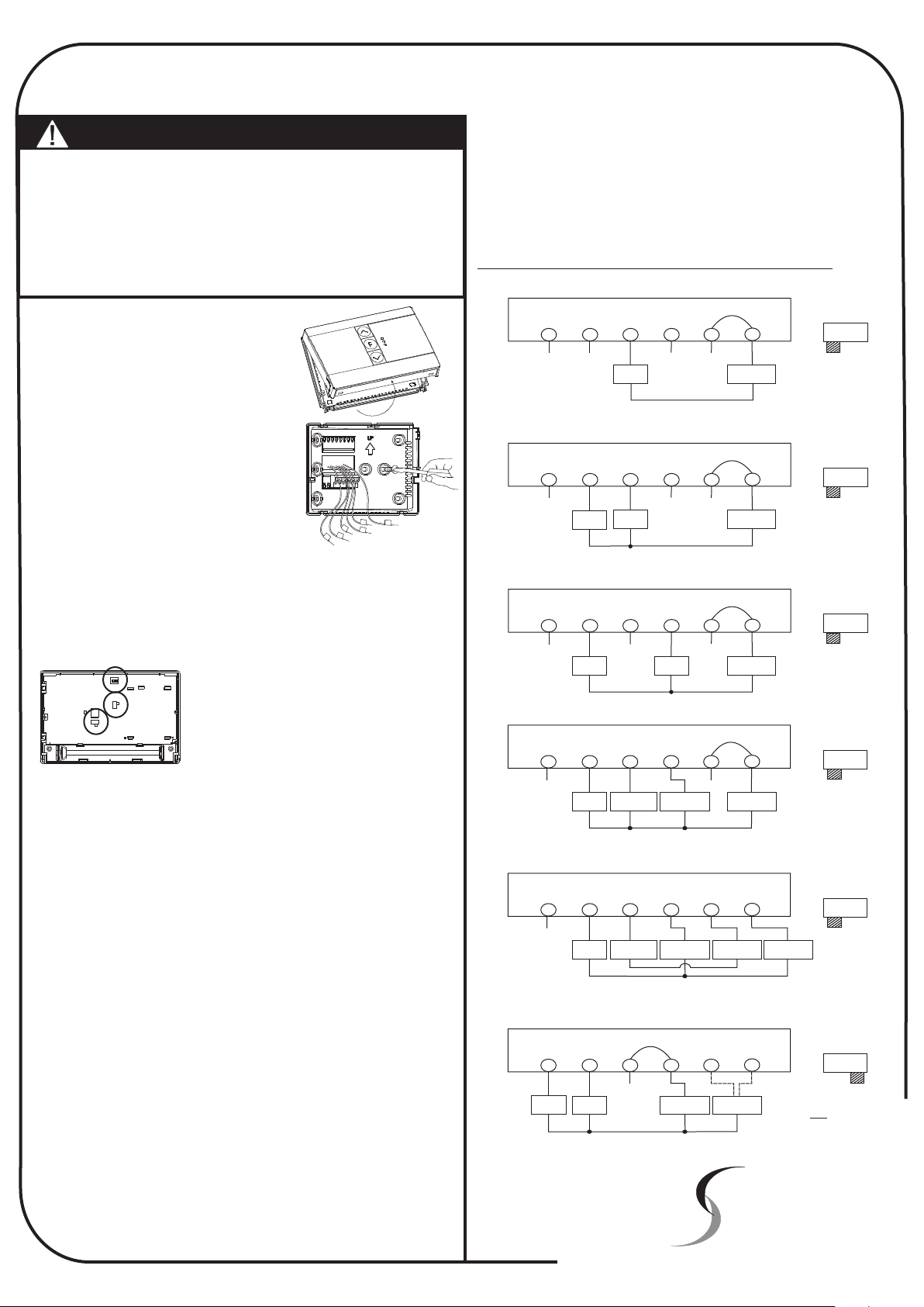
Installation Instructions
R
R
h
/
O
G
Y
W
R
c
/
B
JP2
HG
HE
FAHRENHEIT
1 2 3 4
HP
STD
Note:
These instructions assume the thermostat has
Knowledge of Heating & Air conditioning systems, the terminology
used in these systems and of the HVAC industry requirements.
installer of this
The Smart Temp 44-233 thermostat has been designed to switch voltages up
to 24volt only. Should you wish to control mains (240VAC) equipment the
optional Smart Pak (P/N SP - 03N) interface will be required.
Please contact your place of purchase or Smart Temp Australia should this
interface be required.
It is an offence in Australia for unqualified persons to make any
changes to Airconditioning systems.
Failure to observe this may void equipment and thermostat
warranty, property insurance and cause irreparable damage to the
thermostat or the equipment connected to it.
Installation
Remove the wall plate from the rear of the
thermostat by pressing the release tab on the
base of the thermostat.
Position the wall plate on the wall and pull the
wires through the large opening. Mount the
wall plate with the supplied wall anchors or
other suitable means, ensure the thermostat
base is level to add to the appearance of the
installation.
Referring to the supplied wiring diagrams,
connect the system wires to the appropriate
terminals on the thermostat base plate. Ensure
the screws are tightened securely to prevent potential future problems
caused by loose connections. Push excessive wire length back into the
wall cavity.
If the opening in the wall is large there may be a potential for a draft to blow
through the wall cavity and onto the temperature sensor on the back of the
thermostat. To ensure correct thermostat operation it is important to block
this hole. Failure to do so may cause inaccurate or erratic system
performance.
C/F Switch
Fan
Switch
Mode
Switch
On the back of the 44-233 thermostat there
are two clearly marked selector switches.
These switches are used to select the type of
system the thermostat is controlling (heat
pump or heat with add on cool) and whether
the fan is called by the thermostat (HE) or by
the gas heater (HG) in heating mode.
These switch locations are shown in the diagram above. Adjust these
switches to their correct position to suit the system this thermostat is
controlling.
The Smart Temp 44-233 is a battery powered thermostat and does NOT
require the use of a neutral. If this thermostat is replacing an existing
equipment powered thermostat, disregard the neutral wire.
Failure to heed this warning WILL result in thermostat damage.
2 wire Heat only System
Link
Rc/O
R
X
G W Y
X
Heat
Relay
Rh/B
X
X
24 or mV
Supply
3 wire Heat only System
Link
Rc/O
R
X
Relay
G W Y
Heat
Fan
Relay
Rh/B
X
X
24 or mV
Supply
3 wire Cool only System
Link
Rc/O
Cool
Rh/B
X
24 or mV
Supply
R
X
Relay
G W Y
X
Fan
Relay
4 Wire Heat/Cool System
Link
Rc/O
Cool
Contactor
Rh/B
Heat / Cool
24V Supply
R
G W Y
X X
Fan
Heat relay
Relay
or Valve
System
Selector
STD HP
System
Selector
STD HP
System
Selector
STD HP
System
Selector
STD HP
Snap the two halves of the thermostat back together taking particular care
to align the thermostat pins with the clips on the base plate of the
thermostat. Also, care must be taken that while snapping the thermostat
halves together the small black thermistor bead is not crushed between the
two case halves.
Test all thermostat modes by both raising the set temperature above the
ambient temperature in heat mode and verifying correct heater operation.
Next lower the set temperature to below the ambient temperature with the
thermostat in Cool mode verify the correct operation of the equipment.
Note: This thermostat has a 4 minute compressor protection delay. When
the compressor stops the thermostat will not restart the compressor for 4
minutes. When the delay is active, the word “Heat” or “Cool” will flash in the
LCD.
System Span Settings
The 44-233 thermostat cycles the heating and cooling with a 1C hysteresis
.(Span setting 2). Should you wish to reduce or increase this settings the
“Span” value can be changed.
Press and Hold both the Temp + and Temp - buttons until the LCD shows
“Span X”. Use the Temp + or Temp - button to enter a new setting. To save
the settings dDon't touch any buttons for 5 seconds to exit this mode.
Span 1 = Fast Cycle rate, heating & cooling runs shorter.
Span 2 = Default, optimum value.
Span 3 = Slow Cycle rate, heating & cooling runs longer.
5 Wire Heat/Cool System
R
G W Y
X
Fan
Relay
Heat relay
or Valve
Cool
Contactor
Single Stage Heat Pump
Link
R
G W Y
X
24V
Supply
Fan
Relay
Compressor
Contactor
Smart Temp Australia Pty Ltd
Unit 20, 1488 Ferntree Gully Road
Knoxfield Victoria 3180
www.thermostat.com.au
System
Selector
Rc/O
Rh/B
STD HP
Heat
Heat
24V Supply
Rh/B
Or
Reversing
Valve
Rc/O
Cool
Cool
24V Supply
System
Selector
STD HP
Note Switch in
HP Position
Smart Temp
TM
X
 Loading...