

Page 1
Smart Temp
Thermostats
Model 42 157
Owners Manual
Congratulations on the purchase of your new Electronic Thermostat!
M
AM
4
TEMP
Your new Smart Temp thermostat
design philosophy. As a result, if properly installed your new electronic
programmable thermostat will provide you with years of trouble free and reliable
The Smart Temp 42-157 has been designed to be attractive, highly reliable and
simple to use. Please take the time to read these simple instruction to familiarise
mp
e
T
t
ar
Sm
Operation
Great effort has gone into making the Smart Temp electronic
thermostat an extremely simple thermostat to program and use.
By reading and understanding these simple instruction, you will
realise and use many of the features this thermostat has to offer.
Programming and set up of this product has been designed as a
very methodical procedure. The same buttons (and sequence of
buttons) are used to program and set up this product.
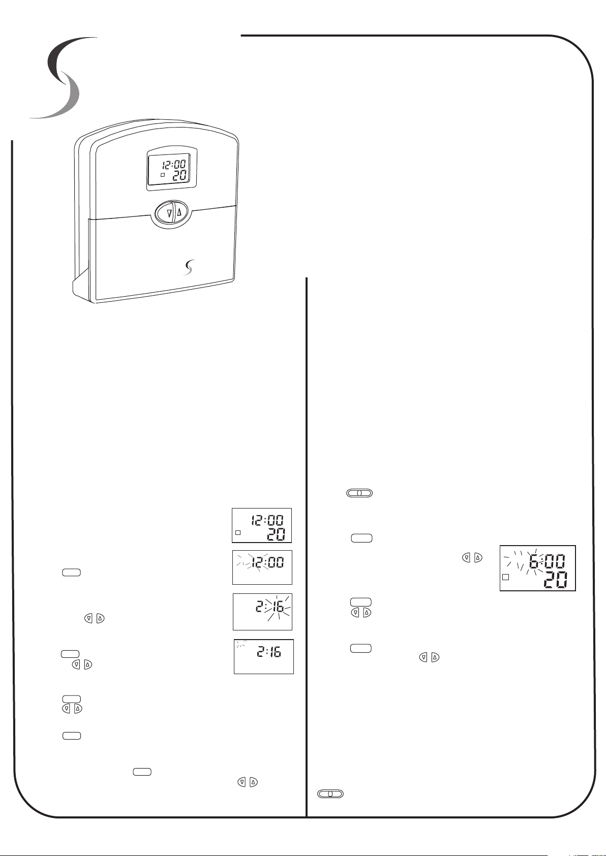
Setting The Clock
As the 42-157 thermostat is a programable thermostat, when you first
place the batteries into the thermostat, (or after you have pressed the
reset button) you must set the real time clock. This is essential as the 42157 thermostat uses this clock to turn on the heating and cooling at the
times that you request.
Setting the clock is a simple procedure that only requires a few key
presses. When the batteries are first installed, the LCD will indicate the
current room temperature and 12AM on the Clock as
shown in Fig1.
In this example, lets set the clock for 2:16PM on
Saturday.
Step 1
Press the button, the display will illuminate, the
DAY/TIME
temperature indication will go blank and the hours digits
will flash as in fig 2.
Step 2
By pressing the buttons adjust the hours to read
or
2PM.
Step 3
Press the button again. Now the minutes flash.
Pressing the will permit you to adjust the minutes
DAY/TIME
or
to “16”.(Fig 3)
Step 4
Press the button again. Now the day will flash as in fig 4.
Press the to adjust the day to read “SA”.
Step 5
Press the button again to return to normal mode. Alternatively by
DAY/TIME
or
DAY/TIME
NOT pressing a button for 20 to 30 seconds the thermostat will
automatically go back into normal mode. The clock is now set.
In this example, Pressing the button cycles through Hours, Minutes
DAY/TIME
and Day. (Indicated by the flashing digit). By pressing the button
permits you to make adjustments to the flashing digit. This same
principal is used through out the programming of this thermostat.
M
AM
1
TEMP
Fig 1
AM
Fig 2
M
PM
Fig 3
M
PM
Fig 4
or
has been built using the best components and
service.
Programming the Thermostat.
The 42-157 is a “5+2” day programmable thermostat; 1 program group is
for the 5 weekdays, 1 program group is for the weekend, hence the 5+2.
Further to this, the 42-157 has 4 programs per day. What this means is
that up to 4 times each day the thermostat will change the temperature of
the home.
As an example, in heating mode - just before you get out of bed in the
morning you may want the home to heat to 20 Deg (Program 1). While
you are at work you may not want the house to get any colder than 15
Deg (Program 2). Just before you arrive home at the end of the day you
may wish the home to be at 21 deg (Program 3), and while you sleep at
night you may want the home to be kept at a cosy 17 Deg (Program 4).
Programming this thermostat is no more difficult than setting the clock. In
programming mode however the thermostat will cycle between Hours,
Minutes and Temperature for Program 1. By continuing to press the
program button it will continue to cycle through Hours, Minutes and
Temperature for Program 2. Then Hours Minutes and Temperature for
Program 3 etc.
Again, after 20 to 30 seconds of NOT pressing a button the thermostat
will return to normal mode.
Step 1
Use the switch to select either heating mode or cooling mode.
(Please note: This thermostat is capable of controlling both a Heating & Cooling system, The use of this
thermostat does not indicate that your home or office has a Heating AND Cooling system installed)
Step 2
Press the button. Program “1” indicator as well as the Weekdays
will be displayed. The “HOURS” and AM or PM on
the LCD will flash. (See fig 5) Press the
button to adjust the hour to the time you wish the
first program to start.
Step 3
Press the button again. Now the minutes will flash for program “1”.
Press the button to adjust the minutes to the time you wish the first
program to start.
Step 4
Press the button again. Now the Temperature for program “1” will
flash. Again, by pressing the buttons you can adjust the desired
temperature for program “1”
Pressing the program button again simply repeats the above procedure
for Programs 2, 3 & 4 for the weekdays, then the 4 weekend programs
(indicated by “SA SU” in the LCD).
Tip.
If you only require 2 or 3 programs per day, simply set the unrequired programs to
HEAT OFF COOL
PROGRAM
or
PROGRAM
or
PROGRAM
the same value as a used program. For example, should you only require 2
programs for the weekend (wake at 7:00am at 20 deg and Sleep at 11:00pm at
17Deg. Simply set program 1, 2 & 3 for 7:00 am at 20Deg and program 4 for
11:00pm at 17Deg. This way, at 7:00 the thermostat will move straight to program 3,
and stay in program 3 until 11:00 pm (program 4 start time)
To adjust the Cooling program. Repeat the above procedure with the
switch in the “Cool” position.
HEAT OFF COOL
or
M T W TH F
AM
1
HEAT
FIG 5
Page 2
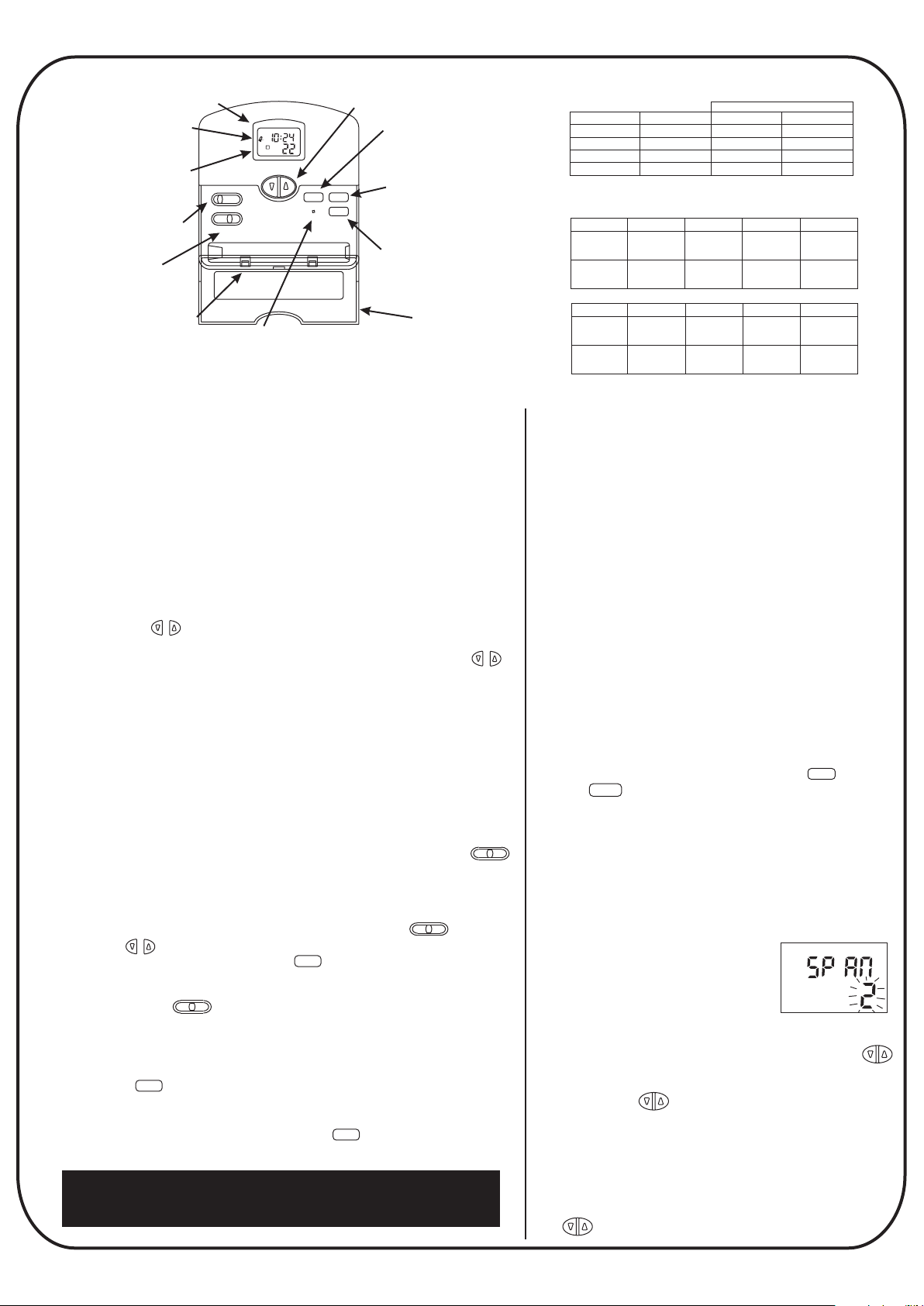
Liquid Crystal Display.
(Shows Day, Time, Temperature,
Program Number, Low Battery and mode).
Low Battery Indicator.
(Flashes when batteries
must be replaced)
INDIGLO night light.
(Operates automatically
Mode Selection Switch
(selects between Heat Off & Cool)
TM
with a button press.)
HEAT OFF COOL
FAN
Fan Switch
(Select Automatic or
continuous fan operation)
Battery Compartment
(Easy front Access for 2
Alkaline “AA” Batteries)
(Push with a paperclip to return
to factory default settings)
TH
PM
3
HEAT TEMP
AUTO
ON
Reset Switch
UP / Down Buttons
(Used to change the set temperature
and for programming adjustments)
Day / Time Button
(Used to enter the
Clock set mode)
DAY/TIME
RESET
PROGRAM
HOLD / RET
Program Button
(Used to enter the
Program Mode)
Hold / Return Button
(Used to override the
program and maintain
a permanent set temperature)
Front Door
(Hides batteries and buttons when
not in use for a neat appearance)
Note: All seven days have the same values
Default Program
Program Number
1
2
3
4
Fill out this table below with your settings
Time
6:00 AM
8:00 AM
4:00PM
10:00 PM
Heat mode
Day
Monday
Friday
Saturday
Sunday
Cool mode
Monday
Friday
Saturday
Sunday
Program 1 Program 2 Program 3
Time
to
Temp
Time
&
Temp
Day
Program 1 Program 2 Program 3
Time
to
Temp
Time
&
Temp
Temperature Deg C
Heat
20 C
16 C
20 C
16 C
Time
Temp
Time
Temp
Time
Temp
Time
Temp
Time
Temp
Time
Temp
Time
Temp
Time
Temp
Cool
26 C
29 C
26 C
28 C
Program 4
Time
Temp
Time
Temp
Program 4
Time
Temp
Time
Temp
Override Functions
The Smart Temp 42-157 has two override modes. These are very useful
should you wish to make changes to the set temperature without
reprogramming the thermostat. The two override modes are described below.
Temporary Override
In this mode, the override temperature change will only last until the NEXT
program starts, hence it being called a “temporary override.” For example, you
might use this type of override when you want the home to be a little warmer
(or cooler) to accommodate a dinner guest. Adjusting the evening program
(program 3) will only last until the sleep program (program 4) begins later that
night, or until it is manually canceled as described below.
To make a Temporary Temperature Override.
Press and hold the button to change the LCD display to indicate the
“SET” or desired temperature. After approximately 1 second, the display will
blink once to indicate the temperature can be adjusted. Press and hold
or
or
to adjust the set temperature to your new desired temperature. You will note
that the Program indicator in the LCD will now flash to indicate that a
temperature override is now active.
Permanent Override.
The Smart Temp 42-157 permits the permanent override of all temperatures
and programs with a simple button press. This may be useful when you go on
holidays and not wish to let the home cool below at 12 deg C, 24 hours per
day, 7 days per week. Another common use of the permanent override is for
those that may not wish to use the Smart Temp 42-157 thermostat as a
programable thermostat, and use it in a “manual thermostat mode”, In this
way you can select a desired permanent temperature and by using the
switch turn the thermostat off or on manually as desired.
To make a permanent Temperature Override.
Should you wish to set a permanent temperature and override all program and
clock functions first select heating or cooling mode using the switch.
Next, using the buttons select the desired temperature. To lock this
temperature permanently simply press the button. The thermostat will
or
HOLD/RET
HEAT OFF COOL
indicate “HOLD” in the LCD confirming the permanently hold function is active.
It is then a simple matter to turn the thermostat off and on at the held
temperature using the switch.
HEAT OFF COOL
To turn OFF Temperature Overrides
When you no longer require a permanent temperature override and wish to
resume normal time clock functions, programs and temperature set points,
simply press the button. The “HOLD” symbol will no longer be shown in
HOLD/RET
the LCD indicating normal thermostat functions have been resumed.
To turn off a temporary override simply press the button twice.
HOLD/RET
HEAT OFF COOL
Making Life Comfortable
Additional Information
Low Battery Warning
The Smart Temp 42-157 is fitted with a two stage low
battery warning. When the batteries are first detected to
be weak the first stage Low battery warning will be
indicated by the low battery symbol in the LCD. It is
important to replace the batteries with Alkaline “AA”
batteries when this symbol is flashing.
When the batteries become too weak to maintain normal
thermostat operation the thermostat enters the second
stage low battery warning which shuts the thermostat
down and flashes the word “BATT” in the thermostat
display.
During a battery replacement You have approximately 1
to 2 minutes once the batteries are removed to place
fresh alkaline batteries in the thermostat before program
data is lost.
Please note: the back light function is suspended
when the low battery indicator is on.
12 or 24 Hour Clock
This thermostat is able to display the time in the
conventional 12 hour “AM / PM” or the 24 Hour time
format. To change the time format press the button
then the button to toggle between both time
PROGRAM
formats.
Span Mode
Your thermostat is set at the factory to maintain the room
temperature to within ½ deg C of the set
(or desired) temperature. For example, in heat mode if
the set temperature is 20 Deg C. The 42-157 will turn the
heating on at 19.5 deg C and off again at 20.5 deg.
This setting has been chosen as it provides the most
comfortable environment under most
conditions. However, if you find the
system cycling (turning off and on) to
quickly or slowly, the thermostats cycle
rate can be increased or decreased
with the “Span” setting.
To enter the “Span” adjustment mode press both the
buttons together for 5 seconds. The display will indicate
the factory default “Span 2”. (Fig 6)
By pressing the buttons will increase or decrease
the span setting.
Span 2 is the factory default setting. Span 1 decreases
the cycle rate, Span 3 increases the cycle rate.
The Span setting effects both the heat and cool mode
equally.
To exit the Span mode, simply press and hold both
The buttons for 5 seconds.
DAY/TIME
Fig 6
Page 3

LCD Back light (INDIGLO )
This thermostat is fitted with a electroluminescent lamp which
activates for easy viewing in the dark. When any button or switch is
pressed the display is illuminated. This back light will remain on for
5 seconds after the last button is pressed.
Troubleshooting
No Display.
1. Check batteries.
2. Press reset and reprogram.
Please note:
If the thermostat is in a low battery condition, the
back light will not operate. It is important to
replace the batteries with two new “AA” Alkaline
batteries when a low battery condition exists.
If the ambient noise level is very low, a quite high pitched sound
may be heard when the back light is on. This is a normal sound
made by the thermostat when the back light is on and is not a
malfunction.
Error Messages
If the thermostat is unable to control your system
due to an unexpected problem the 42-157
thermostat will enter “Error mode”. In this condition
the thermostat flashed “Err” on the LCD (fig7).
In the extremely unlikely event that your thermostat
enters this mode it is recommended that you immediately replace
the thermostat batteries with a new set of “AA” Alkaline batteries
(even if you have just replaced the batteries).
Next, using a paperclip press the reset button which can be found
directly under the button. You will now need to set the clock
and re program the thermostat to ensure correct thermostat
operation.
DAY/TIME
Fig 7
Display Dims.
1. Replace Batteries.
No Back light
1. Replace Batteries.
Program does not change at your desired Setting.
1.Check the time is set properly, note the AM / PM indicator.
2.Check that the thermostat is NOT in Hold mode.
3.Check that the thermostat shows the correct day.
Heating or Cooling does not go On or OFF.
1.Check that the function switch is in the correct position.
2.Some systems require a delay between switching modes.
3.Check circuit breakers (fuses) to equipment.
4.Make sure pilot light (if applicable) on furnace is lit.
5.Replace Batteries in thermostat.
Erratic Display.
1.Replace batteries.
Thermostat permanently displays “HI”, “LO” or “Err”.
1. Replace Batteries and reset.
2. Replace thermostat.
Also Available from Smart
T
emp
The
Smart Zone
Climate System Zoning Solution
Each zone controls the system independently.
The Smart Zone will call for heating or cooling, regardless of the
other zones requirements. This is almost like having two separate
systems. (Note, Both heating & cooling can’t run at the same time,)
Each Zone has its own timer, sensor and set temperature.
Because the Smart Zone is like two separate systems, the
temperature is measured in the zone being heated or cooled.
Further, each zone has its own time clock, therefore automatically
turning on the heating or cooling when you have programmed it!
Divide your home into Living and Sleeping Zones.
Using the Smart Zone you are able to heat or cool the living zones
during the day, and the sleeping zones during the night. Save
energy by only heating or cooling the zones your occupying.
Have two separate temperature Zones
As the Smart Zone is like having two completely independent
heating or cooling systems, each zone can set separate comfort
levels. Therefore eliminating the problem of the upstairs
overheating while maintaining a comfortable temperature
downstairs.
Ideal for Shared accommodation.
If you have a family member living with you, by zoning their area
of the home they have control over their comfort level while
leaving your settings unaffected. This also saves on energy costs as
you only heat or cool the occupied area of the home.
A home climate zoning system
can reduce energy costs by up to 50%
while improving home comfort.
An example of what the system does
Typical 2 story
Gas Centrally
Heated Home
Upstairs temp 27Deg C
C e n t r a l
H e a t i n g
U n i t
Zoned Gas Centrally
Heated home.
Zone Flow
Controller
Central
Heating
Unit
The Smart Zone control board maintains the correct temperature in
the zoned home by controlling the gas central heating unit and
opening or closing the appropriate flow control damper(s) to the
This ensures the correct temperature is maintained throughout your
Zone Flow
Controller
zone(s) that require heating.
entire home.
Downstairs Temp 21 Deg C
Single Thermostat
Upstairs Temp 21 Deg C
Upstairs Thermostat
Downstairs Temp 21 Deg C
Downstairs Thermostat
Page 4

Installation Instructions
Note:
These instructions assume the thermostat has
Knowledge of Heating & Air conditioning systems, the terminology
used in these systems and of the HVAC industry requirements.
It is an offence in Australia for unqualified persons to make
any changes to Airconditioning systems. Failure to observe this
may void equipment and thermostat warranty, property
insurance and cause irreparable damage to the thermostat
or equipment connected to it.
Remove the wall plate from the rear of the
thermostat by pressing the release tab
on the base of the thermostat. (Fig 8)
Position the wall plate on the wall and pull
the wires through the large opening.
Mount the wall plate with the supplied wall
anchors or other suitable means, ensure
the thermostat base is level to add to the
appearance of the installation.
Referring to the supplied wiring diagrams, connect the system
wires to the appropriate terminals on the thermostat base plate.
Ensure the screws are tightened securely to prevent potential
future problems caused by loose connections. Push excessive wire
length back into the wall cavity.
installer of this
Fig 8
The Smart Temp 42-157 thermostat has been designed to switch 24volt
appliances only. Should you wish to control mains, 240VAC equipment an
optional Smart Pak (P/N SP - 03) interface will be required.
Please contact your place of purchase or Smart Temp Australia should this
interface be required.
The Smart Temp 42-157 is a battery powered thermostat and does NOT
require the use of a neutral. If this thermostat is replacing an existing line
powered thermostat, disregard the neutral wire.
Failure to heed this warning WILL result in thermostat damage.
4 Wire Heat/Cool System
Factory Installed Link
Fan
Relay
Y1
Rc
G
X X
Cool
Contactor
Y/O
W/B
Heat relay
or Valve
5 Wire Heat/Cool System
Remove Factory Installed Link
Fan
Relay
G
24V Supply
Cool
Y1
Rc
X
Cool
Contactor
Y/O
W/B
Heat relay
or Valve
Rh
Heat / Cool
24V Supply
Rh
Heat
24V Supply
System
Selector
STD HP
System
Selector
STD HP
If the opening in the wall is large there may be a potential for a
draft to blow through the wall cavity and onto the temperature
sensor on the back of the thermostat. To ensure correct thermostat
operation it is important to block this hole. Failure to do so may
cause inaccurate or erratic system performance.
On the back of the 42-157 thermostat there are three clearly
marked selector switches. These switches are used to select the
temperature display format (deg C or deg F), the type of system
the thermostat is controlling (heat pump
or heat with add on cool) and whether the
Temperature
Display
(SW4)
Fan Option
(SW3)
fan is called by the thermostat (HE) or by
the system (HG)
These switch locations are shown in Fig
9. Adjust these switches to their correct
C
F
HG - HE
NORM - HP
position.
Snap the two halves of the thermostat
Fig 9
back together taking particular care to
align the thermostat pins with the clips on
the base plate of the thermostat (Fig 10).
Set the thermostat to display the correct
time and day taking particular care with
the AM / PM and the day of the week.
Ascertain the customers requirement and
Fig 10
program the thermostat to the customers settings.
Test all thermostat modes by both raising the set temperature
above the ambient temperature in heat mode and verifying correct
heater operation. Next lower the set temperature to below the
ambient temperature with the thermostat in Cool mode verify the
correct operation of the equipment.
Leave a copy of these instructions for the future users of this thermostat
System
Selector
(SW6)
Single Stage Heat Pump
Rc
G
X
Fan
Relay
Compressor
Contactor
2 wire Heat only system
Rc
G
X X
Factory Installed Link
Y1
Y/O
Cool
Mode
Reversing
Factory Installed Link
Y1
Y/O
X X
Or
Valve
Heat relay
or Valve
W/B
W/B
Heat
Mode
3 wire Heat only system
Factory Installed Link
G
Fan
Relay
Y1
Rc
X X
X
Y/O
W/B
Heat relay
or Valve
3 wire Cool only system
Factory Installed Link
G
Fan
Relay
Rc
Cool
24V Supply
Y1
X
Contactor
Y/O
Cool
W/B
X
Rh
Heat Pump
24V Supply
Rh
Heat 24V or
Mimilivolt Supply
Rh
Heat
24V Supply
Rh
X
System
Selector
STD HP
System
Selector
STD HP
System
Selector
STD HP
System
Selector
STD HP
Should you have any questions or require any technical advice
please call Smart Temp Australia P/L on (03) 9763 0094 during
normal business hours.
Smart Temp Australia Pty Ltd
Unit 20, 1488 Ferntree Gully Rd
Knoxfield Vic 3180
www.thermostat.com.au
Smart Temp
Thermostat
X
TM
 Loading...