

Page 1
Smart Temp
Model 42-157B
Owners Manual
Congratulations on the purchase of your new Electronic Thermostat!
Your new Smart Temp thermostat
design philosophy. As a result, if properly installed your new electronic
programmable thermostat will provide you with years of trouble free and
T
HEA
F
C
P
EM
T
The Smart Temp 42-157B has been designed to be attractive, highly reliable and
simple to use. Please take the time to read these simple instruction to familiarise
Temp
Smart
Operation
Great effort has gone into making the Smart Temp electronic
thermostat an extremely simple thermostat to program and use.
By reading and understanding these simple instruction, you will
realise and use many of the features this thermostat has to offer.
Programming and set up of this product has been designed as a
very methodical procedure. The same buttons (and sequence of
buttons) are used to program and set up this product.
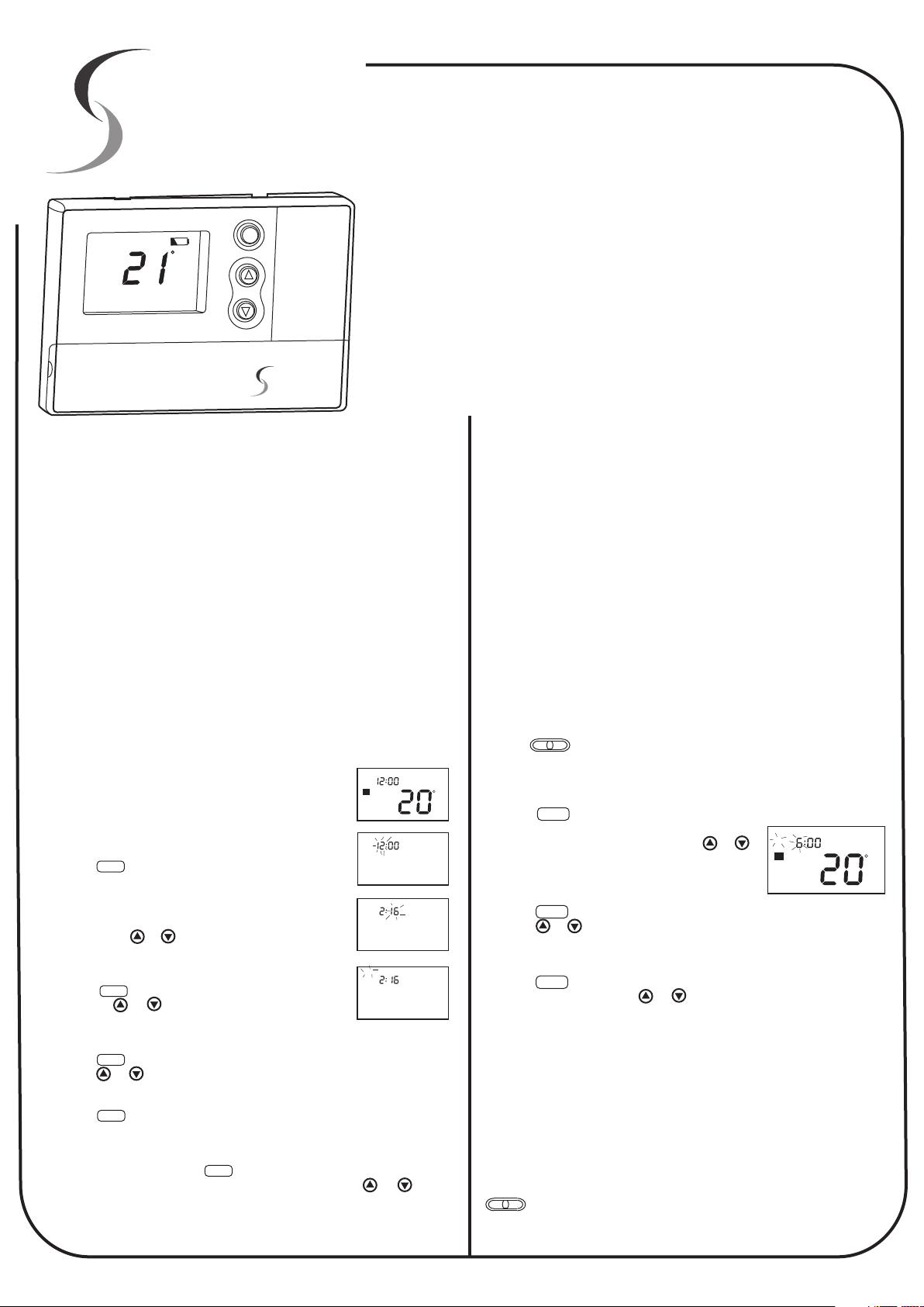
Setting The Clock
As the 42-157B thermostat is a programable thermostat, when you first
place the batteries into the thermostat, (or after you have reset the
thermostat) you must set the clock. This is essential as the 42-157B
thermostat uses this clock to turn on the heating and cooling at the times
that you request.
Setting the clock is a simple procedure that only requires a few key
presses. When the batteries are first installed, the LCD will indicate the
current room temperature and 12AM on the Clock as
shown in Fig1.
In this example, lets set the clock for 2:16PM on
Saturday.
Step 1
Press the button, the display will illuminate, the
DAY/TIME
temperature indication will go blank and the hours digits
will flash as in fig 2.
Step 2
By pressing the or buttons, adjust the hours to
read 2PM.
Step 3
Press the button again. Now the minutes flash.
DAY/TIME
Pressing the or will permit you to adjust the
minutes to “16”.(Fig 3)
Step 4
Press the button again. Now the day will flash as in fig 4.
DAY/TIME
Press the or to adjust the day to read “Sat”.
Step 5
Press the button again to return to normal mode. Alternatively by
DAY/TIME
NOT pressing a button for 20 to 30 seconds the thermostat will
automatically go back into normal mode. The clock is now set.
In this example, Pressing the button cycles through Hours, Minutes
DAY/TIME
and Day. (Indicated by the flashing digit). By pressing the or button
permits you to make adjustments to the flashing digit. This same
principal is used through out the programming of this thermostat.
Mon
AM
4
1
TEMP
Fig 1
AM
Fig 2
PM
Fig 3
Mon
PM
Fig 4
has been built using the best components and
reliable service.
yourself with the function and features offered in this product.
Programming the Thermostat.
The 42-157B is a “5+2” day programmable thermostat; 1 program group
is for the 5 weekdays, 1 program group is for the weekend, hence the
5+2. Further to this, the 42-157B has 4 programs per day. What this
means is that up to 4 times each day the thermostat will automatically
change the temperature of the home.
As an example, in heating mode - just before you get out of bed in the
morning you may want the home to heat to 20 Deg (Program 1). While
you are at work you may not want your home to get any colder than 15
Deg (Program 2). Just before you arrive home at the end of the day you
may wish the home to be at 21 deg (Program 3), and while you sleep at
night you may want the home to be kept at a cosy 17 Deg (Program 4).
Programming this thermostat to follow your customised profile is no more
difficult than setting the clock. By tapping the program button the
thermostat will step between Hours, Minutes and Temperature for
Program 1. By continuing to tap the program button it will continue to
cycle through Hours, Minutes and Temperature for Program 2. Then
Hours Minutes and Temperature for Program 3 etc.
Again, after 20 to 30 seconds of NOT pressing a button the thermostat
will return to normal mode.
Step 1
Use the switch to select either heating mode or cooling mode.
(Please note: This thermostat is capable of controlling both a Heating & Cooling system, The use of this
thermostat does not indicate that your home or office has a Heating AND Cooling system installed)
C
Step 2
Press the button. Program “1” indicator as well as the Weekdays
will be displayed. The “HOURS” and AM or PM on
the LCD will flash. (See fig 5) Press the or
button to adjust the hour to the time you wish the
first program to start.
Step 3
Press the button again. Now the minutes will flash for program “1”.
Press the or button to adjust the minutes to the time you wish the
first program to start.
Step 4
Press the button again. Now the Temperature for program “1” will
flash. Again, by pressing the or buttons you can adjust the desired
temperature for program “1”
Pressing the program button again simply repeats the above procedure
for Programs 2, 3 & 4 for the weekdays, then the 4 weekend programs
(indicated by “Sat” & “Sun” in the LCD).
Tip.
If you only require 2 or 3 programs per day, simply set the un required programs to
HEAT OFF COOL
PROGRAM
PROGRAM
PROGRAM
the same value as a used program. For example, should you only require 2
programs for the weekend (wake at 7:00am at 20 deg and Sleep at 11:00pm at
17Deg. Simply set program 1, 2 & 3 for 7:00 am at 20Deg and program 4 for
11:00pm at 17Deg. This way, at 7:00 the thermostat will move straight to program 3,
and stay in program 3 until 11:00 pm (program 4 start time)
To adjust the Cooling program. Repeat the above procedure with the
switch in the “Cool” position.
HEAT OFF COOL
Mon Tue Wed Thu Fri
AM
1
HEAT
FIG 5
C
Page 2
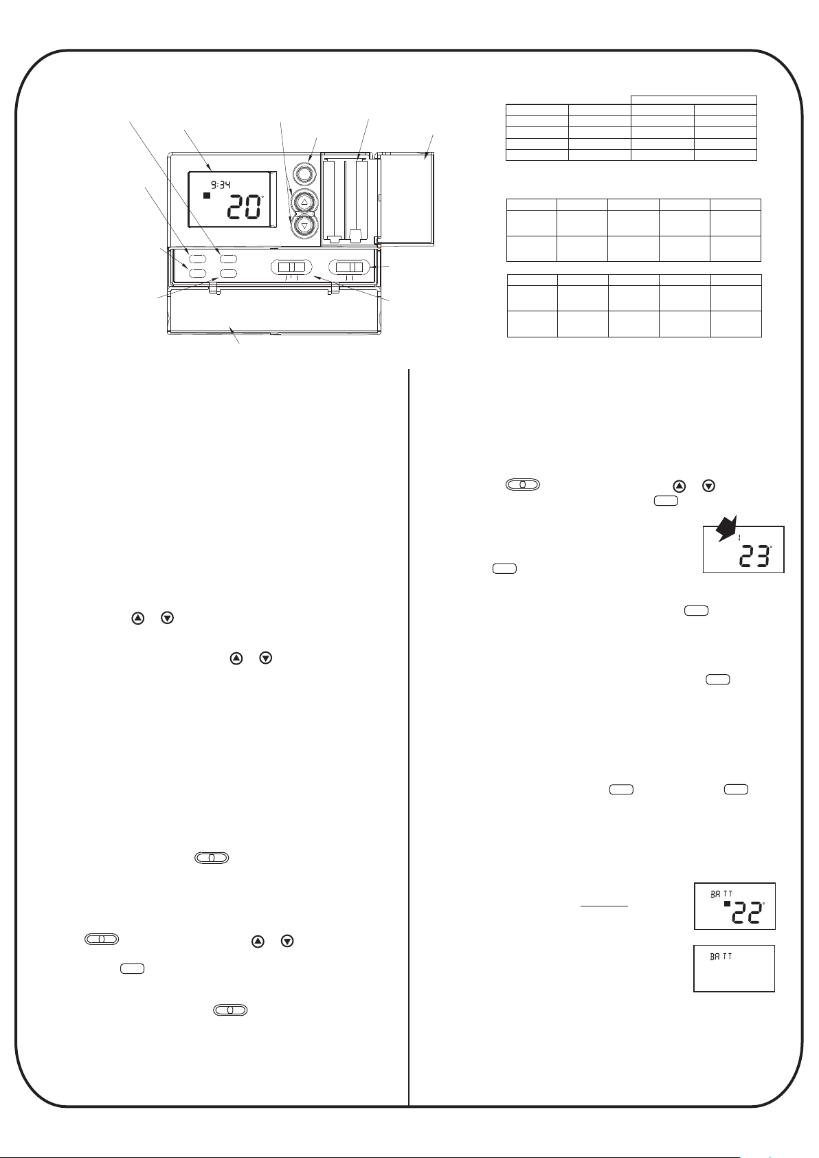
heat offcool on auto
day/time
filter
program hold
system
fan
LCD Display:Shows
Time,Day,Temperature,
Program Number,and
other feature information
as required.
L
Backlight key
Battery Compartment:
Front access allows
easy insertion of two
AA 1.5V batteries.
Up and Down Key:Key for
changing the Temperature
setting. Also used for increasing
and decreasing sele ctions in the
Time,Program,and Span
functions.
/return
Fan Switch: Fan
switch for Automatic
or Continuous fan
operation.
System Switch:
Selector switch for
Heat,Cool,and Off.
Day/Time Key:
Used for entering
the Clock setting
mode.Use with the
Up and Down keys
to set the time and day.
Filter Key:Resets
filter change
counter to zero.
Program Key: Used
for entering and modifying
Programs. Use with the Up
and Down keys to set
times and temperatures.
Press when in Clock setting
mode to select between 12
and 24 hour clock modes.
Hold/Return Key:Used for
setting a permanent(vacation)
hold,and for returning to the
normal display from Day &
Time setting, Programming,or
Span setting modes.
Front Door:
Battery cover
Open with one
finger from top.
Front Door:
Cover keys Open with one finger from left or right.
Mon
AM
2
TEMP
C
Functions
The Smart Temp 42-157B has three override modes. These are
very useful should you wish to make changes to the set
temperature without completely reprogramming the thermostat.
The three override modes are described below.
Temporary Override
In this mode, the override temperature change will only last until
the NEXT program starts, hence it being called a “temporary
override.” For example, you might use this type of override when
you want the home to be a little warmer (or cooler) to
accommodate a dinner guest. Adjusting the evening program
(program 3) will only last until the sleep program (program 4)
begins later that night, or until it is manually canceled as
described below.
To make a Temporary Temperature Override.
Press and hold the or button to change the LCD display to
indicate the “SET” or desired temperature. After approximately 1
second, the display will blink once to indicate the temperature can
now be adjusted. Press and hold the or button to adjust the
set temperature to your new desired value. You will note that the
Program indicator in the LCD now flashes to indicate that a
temporary temperature override is now active.
Permanent Override.
The Smart Temp 42-157 permits the permanent override of all
temperatures and programs with a simple button press. This may
be useful when you go on holidays and not wish to let the home
cool below at 12 deg C, 24 hours per day, 7 days per week.
Another common use of the permanent override is for those that
may not wish to use the Smart Temp 42-157B thermostat as a
programable thermostat, and use it in a “manual thermostat
mode”, In this way you can select a desired permanent
temperature and by using the switch turn the thermostat
off or on manually as desired.
To make a permanent Temperature Override.
Should you wish to set a permanent temperature and override all
program and clock functions first select heating or cooling mode
using the switch. Next, using the or buttons select
the desired temperature. To lock this temperature permanently
simply press the button once. The thermostat will indicate
“HOLD” in the LCD confirming the permanently hold function is
active. It is then a simple matter to turn the thermostat off and on
at the held temperature using the switch.
HEAT OFF COOL
HOLD/RET
HEAT OFF COOL
HEAT OFF COOL
Note: All seven days have the same values
Default Program
Program Number
1
2
3
4
Fill out this table below with your settings
Time
6:00 AM
8:00 AM
4:00PM
10:00 PM
Heat mode
Day
Monday
Friday
Saturday
Sunday
Cool mode
Monday
Friday
Saturday
Sunday
Program 1 Program 2 Program 3
Time
to
Temp
Time
&
Temp
Day
Program 1 Program 2 Program 3
Time
to
Temp
Time
&
Temp
To set a Holiday period Temperature Override.
Should it be desirable, you can set a permanent temperature
override that will automatically cancel itself in a given number of
days. For example, you may be going on holiday for 14 days and
would like the home to be warm or cool to greet you when you
return.
To set the Holiday override first select either heating or cooling
mode with the switch. Next, using the or button set
your desired temperature. Now, press the button twice to set
HEAT OFF COOL
the “holiday override mode”.
The LCD will look like the example shown in fig 6.
Tapping the button the LCD will increase
Day / time
the counter to show the number of days until
the holiday override expires and normal thermostat operation
begins. If you set too many days, pressing the button will
permit you to reduce the day counter.
To cancel an active Override
When you no longer require a temperature override and wish to
resume normal thermostat operation simply tap the button
until the LCD no longer shows the word “Hold”. The 42-157B will
now alter the homes temperature automatically according to your
programmed schedule.
12 or 24 Hour Clock
The 42-157B thermostat is able to display the time in the
conventional 12 hour “AM / PM” or the 24 Hour time format. To
change the time format press the button then the
button to toggle the time format.
Low Battery Warning
Your Smart Temp 42-157B is fitted with a two stage low battery
warning. When the batteries are first detected to be weak the first
stage Low battery warning will be indicated by the low battery
symbol in the LCD. (See fig 7a). It is important
to replace the batteries with Alkaline “AA”
batteries when this symbol is flashing. When the
batteries become too weak to maintain normal
thermostat operation the thermostat enters the
second stage low battery warning (fig 7b) which
shuts the thermostat down.
During a battery replacement process you have
approximately 2 to 5 minutes once the batteries are removed to
place fresh alkaline batteries in the thermostat before program
data is lost.
Please note: the back light function is suspended
when the low battery indicator is on.
Temperature Deg C
Heat
20 C
16 C
20 C
16 C
Time
Temp
Time
Temp
Time
Temp
Time
Temp
Day / time
Time
Temp
Time
Temp
Time
Temp
Time
Temp
HOLD/RET
Progam
Cool
26 C
29 C
26 C
28 C
Program 4
Time
Temp
Time
Temp
Program 4
Time
Temp
Time
Temp
TEMP
HOLD/RET
HEAT
Fig 7a
Fig 7b
Fig 6
Progam
4
Hold
C
Fri
C
Page 3

Auto Recovery Mode
Your 42-157B thermostat has the ability to use advanced energy
management techniques if activated by your installer.
Auto Recovery mode will calculate the most energy efficient time to
control your heating or cooling system to ensure your ideal
programmed comfort temperature is reached by your programmed
start time.
When your thermostat is in recovery mode the LCD
will alternate between the word “RECO” and the
current time, See fig 8.
Thu
2
HEAT
Fig 8
Notes on recovery mode
nRecovery mode is enabled / disabled by a switch marked
“recovery” on the inside of the thermostat. This is normally set by
the installer.
nRecovery mode will not operate if the LCD shows the word
“HOLD”
nThe Recovery function can be cancelled by pressing the
HOLD/RET
button. The recovery mode will then be transferred to the next
scheduled event.
Filter Change Indicator
To ensure your heating and cooling system is operating at peak
performance, your 42-157B thermostat monitors the total time your
heating & cooling system has been running. When 400 hours of run
time has elapsed the word “FILT” will be alternatively displayed with
the clock on the LCD to remind you to clean or replace your return
air filter (if fitted) see fig 9a.
To review the total filter time
Press the button to review the total filter time.
In the example shown the filter has been used for
232 hours and 19 minutes. Fig 9b.
To reset the counter and cancel the filter warning
press and hold the button for 5 seconds.
FILTER
FILTER
Fig 9a
H
Fig 9b
Troubleshooting
No Display.
1. Check batteries.
2. Reset thermostat by removing batteries and pressing any
button - replace batteries.
Display Dims.
C
1. Replace Batteries.
No Back light
1. Replace Batteries.
Program does not appear to be operating correctly.
1. Check the time is set properly, note the AM / PM indicator.
2. Check that the thermostat is NOT in Hold mode.
3. Check that the thermostat shows the correct day.
4. Ensure the Heat/Off/Cool switch is not OFF.
Heating or Cooling does not turn On.
1. Check that the function switch is in the correct position.
2. Some systems require a 4 minute delay before starting.
3. Check circuit breakers (fuses) to equipment.
4. Make sure pilot light (if applicable) on heater is lit.
5. Replace Batteries in thermostat.
Erratic Display.
1. Replace batteries.
Thermostat permanently displays “HI”, “LO” or “Err”.
1. Replace Batteries and reset.
2. Replace thermostat.
Specifications
Systems Controlled Gas / Oil / Hydronic Heating
M
Electric Cooling
Single Stage Heat Pump
Backlighting.
The 42-157B is fitted with an electro-luminescent back light. When
any key is pressed the back light will turn on and remain on for 8
seconds after the last button has been pressed. If ambient noise
level is very low you may hear a high pitch noise when the back light
is on. This is normal and is there is no cause for concern.
When the thermostat battery is low, the back light function is
suspended. Replace the batteries with 2 “AA” alkaline only.
Span Setting
For the best compromise of energy management and comfort your
42-157B will control your heating and cooling to within 1 deg C of
your set temperature in both heating and cooling modes (Span 2).
In all but the most unusual circumstances you should find this
setting is adequate. Should it be required, you can change this
factory default value to widen or tighten the control tolerance by
pressing both the and together and choosing
an alternate setting. (Fig 10)
Span 1 will maintain your room temperature very
Fig 10
close to your set temperature by turning your heating or cooling
system on and off at relatively short intervals. This is the least
energy efficient setting.
Span 2 - factory default setting.
Span 3 will permit your room temperature to vary slightly from your
set temperature by delaying the start of your heating or cooling
system and running it longer. This is the most energy efficient
setting.
Switching Voltage Millivolt to 24VAC @ 2amps max
Resolution 1 deg C (Heating & Cooling)
Programming 5+2 Day - 4 events per day
Accuracy +/- 0.5C
Control Range 7 to 35C
Display Range 0 to 37C
Compressor delay protection Heat / Cool - 4 mins on cool only
Heat pump - 4 mins on Heat & Cool
Holiday Delay 1 to 255 days (adjustable)
Filter Warning 400 Hours ( non adjustable)
Size 140 x 93 x 25mm
Battery life 12 to 15 months (Alkaline only)
For technical support please contact Smart Temp Australia P/L
or an authorised sales / service agent.
Due to continual product improvement these specifications
are subject to change without notice.
Note: When your thermostat is re-set, the factory default value
of Span 2 will be restored.
Page 4

Installation Instructions
Note:
These instructions assume the thermostat has
knowledge of Heating & Air conditioning systems, the terminology
used in these systems and of the HVAC industry requirements.
It is an offence in Australia for unqualified persons to make any changes
to Airconditioning systems. Failure to observe this may void equipment and
thermostat warranty, property insurance and cause irreparable damage to the
thermostat or equipment connected to it.
Remove the wall plate from the rear of the
thermostat by pressing the release tabs on the
top and bottom of the thermostat ands swinging
the base away. (Fig 10)
Position the wall plate on the wall and pull the
wires through the large opening. Mount the
wall plate with the supplied wall anchors or
other suitable means, ensure the thermostat
base is level to add to the appearance of the installation.
Referring to the supplied wiring diagrams, connect the system wires to the
appropriate terminals on the thermostat base plate. Ensure the screws are
tightened securely to prevent potential problems caused by loose
connections. Push excessive wire length back into the wall cavity.
If the opening in the wall is large there may be a potential for a draft to blow
through the wall cavity and onto the temperature sensor on the back of the
thermostat. To ensure correct thermostat operation it is important to block
this hole. Failure to do so may cause inaccurate or erratic system
performance.
On the back of the 42-157B thermostat there are three clearly marked
selector switches. These switches are used to select the temperature
display format, deg C or deg F, the type of system the thermostat is
controlling (heat pump or heat with add on cool) and whether the fan is
called by the thermostat HE (Heating Electric) or by the system HG
(Heating Gas) .These switch locations are shown in Fig 11. Adjust these
switches to their correct position to suit the type of system controlled.
Snap the two halves of the thermostat
back together taking particular care to
align the thermostat pins with the clips
on the base plate of the thermostat
and that the temperature sensing
bead will not become crushed
between the two case halves.
Test all thermostat modes by both
raising the set temperature above the
ambient temperature in heat mode
and verifying correct heater operation. Next lower the set temperature to
below the ambient temperature with the thermostat in Cool mode and verify
the correct operation of the cooling equipment.
Please Note: The Smart Temp 42-157B thermostat is a low voltage
thermostat only. Do NOT directly switch 240VAC equipment or damage will
result. Should it be necessary to switch 240VAC equipment the optional
Smart Pak 03N will be required. See fig 12 below.
F
C
T
HEA
4 low voltage wires
(Active, Heat, Cool & Fan)
Should you have any questions or require any technical advice
please call Smart Temp Australia P/L on (03) 9763 0094
during normal business hours.
installer of this
CENTIGRADE FAHRENHEIT
A/C System
Fuse
3 - Heat
2 - Cool
1 - Fan
R- Active
240/24V Interface
Fig 10
Auto Recovery
1 2 3 4
ENABLE DISABLE
HP
STD
System Selector
HE
HG
Fan Option
Fig 11
A
N
1
2
3
240 VAC
Fan
Cool
Heat
The Smart Temp 42-157 thermostat has been designed to switch 24volt
appliances only. Should you wish to control mains, 240VAC equipment an
optional Smart Pak (P/N SP - 03) interface will be required.
Please contact your place of purchase or Smart Temp Australia should this
interface be required.
The Smart Temp 42-157 is a battery powered thermostat and does NOT
require the use of a neutral. If this thermostat is replacing an existing line
X
powered thermostat, disregard the neutral wire.
Failure to heed this warning WILL result in thermostat damage.
4 Wire Heat/Cool System
Factory Installed Link
G
Fan
Relay
Rc
X
Heat / Cool
24V Supply
Rh
Y/O
Cool
Contactor
W/B
Heat relay
or Valve
Y1
X
System
Selector
STD HP
5 Wire Heat/Cool System
System
Selector
G
Rc
Fan
Relay
Cool
Supply
Supply
Single Stage Heat Pump
Factory Installed Link
G
Rc
X
Fan
Relay
Heat pump
24V Supply
Two wire Heat only
G
Rc
X X
Heat / Cool
24V Supply
Three wire Heat only
Factory Installed Link
G
Rc
X
Fan
Relay
Heat / Cool
24V Supply
Three wire Cool only
Factory Installed Link
G
Rc
Fan
Cool
24V Supply
Relay
Rh
Heat
Rh
Rh
Rh
Rh
Y/O
Cool
Contactor
Y/O
Cool
Reversing
Y/O
X
Y/O
X
Y/O
Cool relay
or valve
or
Valve
Heat relay
or Valve
Heat relay
or Valve
W/B
Heat relay
or Valve
W/B
Heat
W/B
W/B
W/B
Y1
X
Y1
Compressor
Contactor
Y1
X
Y1
X
Y1
XXX
STD HP
System
Selector
STD HP
System
Selector
STD HP
System
Selector
STD HP
System
Selector
STD HP
Smart Temp Australia Pty Ltd
Unit 20, 1488 Ferntree Gully Road
Knoxfield Victoria 3180
www.thermostat.com.au
Smart Temp
 Loading...