

Page 1

480C
Version 1.1
Installation and User’s Guide
Optical Whiteboard Capture System
Technologies Inc.
Page 2

FCC Warning
This equipment has been tested and found to comply with the limits for a "Class B" digital device, pursuant to Part 15 of
the FCC rules. These limits are designed to provide reasonable protection against harmful interference in a residential
installation. This equipment generates, uses, and can radiate radio frequency energy and, if not installed and used in
accordance with the instruction, may cause harmful interference to radio communications. However, there is no
guarantee that interference will not occur in a particular installation. If this equipment does cause harmful interference
to radio or television reception (this can be determined by turning the equipment off and on) the user is encouraged to
try to correct the interference by one or more of the following measures:
l
Reorient or relocate the receiving antenna.
l
Increase the separation between the equipment and receiver.
l
Connect the equipment into an outlet on a circuit different from that to which the receiver is connected.
l
Consult the dealer or an experienced radio/TV technician for help.
Any changes or modifications to this "Class B" digital device that have not been expressly approved by SMART
Technologies Inc. could void the user's authority to operate the equipment.
Trademark Notice
Hawkeye is a trademark of SMART Technologies Inc. All other trademarks are for identification purposes only and are
the property of their respective owners.
Copyright Notice
The use and copying of this product is subject to a license agreement. Any other use is prohibited. No part of this
publication may be reproduced, transmitted, transcribed, stored in a retrieval system or translated into any language in
any form by any means without the prior written consent of SMART Technologies Inc. Information in this manual is
subject to change without notice and does not represent a commitment on the part of the vendor.
© 1997-2001 SMART Technologies Inc. Printed in Canada 05/2001
U.S. Patent No. 5,528,290. Other U.S. and foreign patents pending.
All rights reserved.
Page 3

Important Information
Please read this manual carefully before setting up and using Hawkeye 480C. With
proper care, your Hawkeye system should provide years of trouble-free service.
About this Guide
This guide explains how to install and use the standard version of the Hawkeye Camera Boom
with a Control Unit. It doesn’t explain the Status Board version which automatically updates a
captured image of your whiteboard every 30 seconds. For that information, refer to the
Hawkeye 480C Status Board Installation and User’s Guide.
This guide also doesn’t explain Hawkeye CAM, which is a different product that consists of a
Camera Boom connected directly to a computer. That product is explained in the Hawkeye
CAM Installation and User’s Guide.
WARNING
The Hawkeye Camera Boom contains precisely aligned camera units.
Handle it with care. Do not open the Camera Boom casing.
Other Warnings and Safety Precautions
For operating safety and to avoid damage to your Hawkeye 480C, read carefully and
observe the following instructions.
Avoid installing Hawkeye 480C near radio transmitting devices. The electromagnetic
1
radiation created by radio transmitting devices may reduce the quality of images
captured by Hawkeye 480C.
Avoid setting up and using Hawkeye 480C in an area with excessive levels of dust,
2
humidity or cigarette smoke.
When the Hawkeye 480C installation is complete, make sure all of the security hex
3
screws have been tightened. There are two security hex screws at the bottom corners
of the Control Unit and one in the Camera Boom base. These screws ensure the
equipment can’t be accidentally knocked free from the wall brackets. The screws also
help prevent unauthorized people from taking the equipment.
Avoid exposing Hawkeye 480C to extreme heat or cold. Hawkeye 480C’s operating
4
temperature range is from 41°°°°F to 95°°°°F (5°°°°C to 35°°°°C) with up to 90% humidity noncondensing. The Hawkeye 480C shipping and storage range is from -40°°°°F to 95°°°°F
(-40°°°°C to 35°°°°C) with up to 95% humidity non-condensing.
Don’t block the vents located at the top and bottom of the Control Unit. In order for the
5
Control Unit to maintain its operating temperature these vents must remain exposed.
Disconnect the power cord from the Hawkeye Control Unit during electrical storms.
6
This product is equipped with a three-wire grounding-type plug. This plug will only fit
7
into a grounding-type power outlet. If you’re unable to insert the plug into the outlet,
contact your electrician to replace your obsolete outlet. Do not defeat the safety
purpose of the grounding-type plug.
Handle the power cable carefully and avoid excessive bending. The power cable
8
should be routed so that it’s unlikely to be walked on or pinched by items placed upon
or against it. Do not attempt to modify the power cable.
Important Information
Page 4

Cleaning the Hawkeye Control Unit
Clean the Control Unit with a soft cloth and mild detergent cleanser. Never use solvents or
an abrasive cleanser, as these may damage the surface of the Control Unit.
Important Information
Page 5

Contents
Hawkeye Overview.......................................................... 1
Camera Boom........................................................................... 1
Control Unit ............................................................................... 1
Image-Saving Software............................................................. 2
Hawkeye Features .................................................................... 2
Stand-Alone Control Unit .......................................................... 2
Networked Control Unit............................................................. 3
PART 1: INSTALLING HAWKEYE 480C
Installing the Camera Boom and Control Unit.............. 4
Single Camera Boom with a Control Unit ................................. 4
Multiple Camera Booms with a Control Unit ............................. 4
Unpacking and Checking Components ....................................4
Mounting a Camera Boom on the Wall..................................... 5
Connecting Multiple Camera Booms ........................................ 7
Mounting the Control Unit on the Wall ...................................... 9
Connecting a Camera Boom to the Control Unit .................... 11
Configuring a Stand-Alone Control Unit..................... 14
Connecting the Control Unit to a Local Printer........................ 14
Connecting the Control Unit to a Power Source ..................... 15
Specifying a Local Printer Type .............................................. 17
Configuring a Networked Control Unit........................ 19
DHCP Network........................................................................ 19
Static IP Network .................................................................... 19
Connecting the Control Unit to a Network............................... 20
Connecting the Control Unit to a Power Source ..................... 21
Configuring Network Settings at the Control Unit ................... 23
Configuring Network Settings Using a Web Browser ............. 29
Specifying a Network Printer at the Control Unit..................... 31
Specifying a Network Printer Using a Web Browser............... 34
Configuring the Image-Saving Software..................... 35
Installing the Image-Saving Software ..................................... 35
Specifying the IP Address of the Computer ............................ 35
Specifying the Captured Images Directory ............................. 36
Refining Image Alignment and Adding an
Image Frame.................................................................. 37
Numbering Camera Booms .................................................... 37
Refining Image Alignment....................................................... 39
Adding/Removing the Image Frame at the Control Unit ......... 43
Adding/Removing the Image Frame Using a Web Browser ... 44
Updating Control Unit Firmware.................................. 45
PART 2: USING HAWKEYE 480C
Using Hawkeye at a Whiteboard.................................. 47
Reactivating the Control Unit .................................................. 47
Starting or Resuming a Session ............................................. 47
Capturing the Notes from Your Whiteboard ........................... 49
Adjusting Control Unit Screen Brightness............................... 49
Printing Captured Images at the Control Unit ......................... 51
Deleting Captured Images at the Control Unit ........................ 52
Ending a Session .................................................................... 52
Contents
Page 6

Working with Captured Images at Your Desk............. 54
Using the Image-Saving Software Files .................................. 54
Using the Sessions Page ........................................................56
Customer Support......................................................... 58
Contacting SMART Technical Support ...................................58
Other SMART Contacts ..........................................................58
Product Warranty ....................................................................58
Index ............................................................................... 60
Contents
Page 7
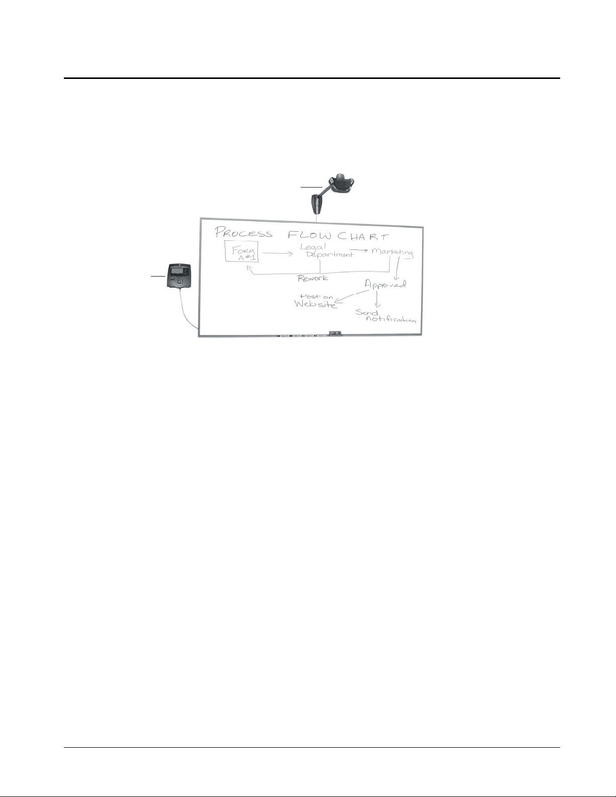
Hawkeye Overview
Hawkeye 480C is an optical whiteboard capture system that works with your existing
whiteboard and markers. It enables you to capture, print and distribute whiteboard notes as
full-color, digitally enhanced images. You can even use Hawkeye to capture, print and
distribute flip chart pages that have been taped onto a whiteboard.
Basically, Hawkeye consists of two parts: a fixed Camera Boom and a Control Unit.
Camera Boom
Control Unit
Hawkeye 480C Optical Whiteboard Capture System
Hawkeye also comes with Image-Saving Software that can be installed on a computer
within the same local area network as the Control Unit in order to automatically save
captured images on that computer.
Camera Boom
The Camera Boom can be mounted above any standard whiteboard. It includes three digital
cameras, each with fixed focus and auto exposure. The digital cameras in the Camera
Boom take color photographs of the notes you’ve made on your whiteboard. Before the
image is stored on the Control Unit, the photographs taken by the three cameras are
stitched together, the background is whitened, the writing is sharpened and the color is
improved.
Control Unit
The Control Unit includes an embedded processor with a built-in Web server, as well as
firmware for capturing and enhancing images. It stores approximately 20 captured images
at a time. A small screen on the Control Unit displays easy-to-follow instructions. Buttons
on the Control Unit enable you to configure the Control Unit, capture whiteboard images
and perform various other functions.
You can connect the Control Unit to a network and use Image-Saving Software to
automatically save images captured by the Control Unit to a computer within the same
network. You can use the Control Unit with a local printer or a network printer. You can
even use Hawkeye with multiple whiteboards. As many as four Camera Booms can be
controlled by one Control Unit.
Hawkeye Overview
1
Page 8

Bottom View
of Control Unit
Parallel Printer Port
Camera Boom
IEEE 1394 Port
Network Port
Control Unit Ports in Use
Power Socket
Image-Saving Software
The Image-Saving Software that comes with the Hawkeye 480C automatically saves
images captured at the Control Unit to a specified file path on a computer within the same
network. The software generates an index of the images captured in each session as an
HTML page that can be opened using a Web browser. This index enables you to view,
copy and print captured images at your desk.
Hawkeye Features
Once it has been installed, Hawkeye is always ready. Because it simply photographs what
you’ve written on your whiteboard, Hawkeye is also always reliable. To capture the information
on your whiteboard, just press the Capture button on the Control Unit.
Hawkeye can be used with or without a network connection. If the Control Unit is connected to
a local area network, you can use the Image-Saving Software to automatically save every
image captured at the Control Unit to a computer within the same network. With a network
connection, current images are also immediately available upon capture from the IP address or
host name displayed on the Control Unit.
If the Control Unit isn’t connected to a network, the images can’t be saved. In this case the
captured images must be printed and distributed in hard copy.
Stand-Alone Control Unit
You don’t need a network connection or even a computer to use Hawkeye. All you need is the
Hawkeye Camera Boom and Control Unit, plus a printer. You can capture, delete and print
whiteboard notes all within the same room.
You can store approximately 20 images on a stand-alone Control Unit, but you can’t save the
images. Once you start a new session or exceed the maximum number of images allowed,
previously captured images will no longer be available on the Control Unit. The images you
capture on a stand-alone Control Unit must be distributed in hard copy. In order to do that,
you’ll need to attach a printer to the Control Unit.
2
Hawkeye Overview
Page 9

Networked Control Unit
A Hawkeye Control Unit that has been connected to a network can do everything a stand-alone
Control Unit can do and more. If your Control Unit is connected to a local area network, every
image captured at the Control Unit can be automatically saved on a computer within the same
network. Just install and configure the Image-Saving Software on a computer networked to the
Control Unit, and every image you capture at the Control Unit will be automatically saved to a
file on that computer. Anyone with a copy of these files can then view, copy and print the
images captured by Hawkeye.
With a network connection, current images are also immediately available upon capture from
the Sessions page. To access this page, open a Web browser to the IP address or host name
of the Control Unit.
Hawkeye Overview
3
Page 10

Installing the Camera Boom and Control Unit
If you have one whiteboard in the room, you only need one Camera Boom. However, if
you have more than one whiteboard, you may want to take advantage of Hawkeye’s ability
to control multiple Camera Booms from a single Control Unit. You can use one Control
Unit to capture the notes from up to four different whiteboards by mounting a Camera
Boom above each one. The installation procedure varies, depending on whether you plan
to use one Camera Boom or several.
Single Camera Boom with a Control Unit
To install a Camera Boom and Control Unit that captures the notes from one whiteboard,
you’ll need to:
Mount the Camera Boom on the wall.
1
Mount the Control Unit on the wall.
2
Connect the Camera Boom to the Control Unit.
3
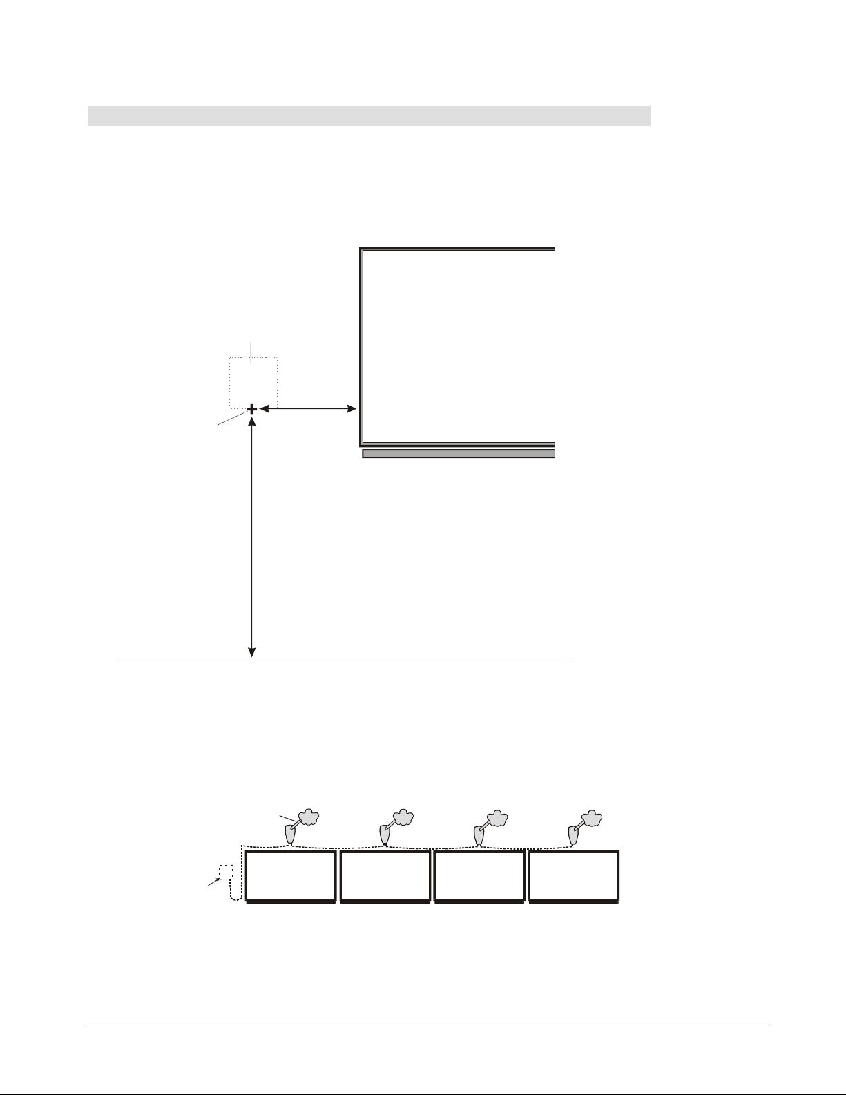
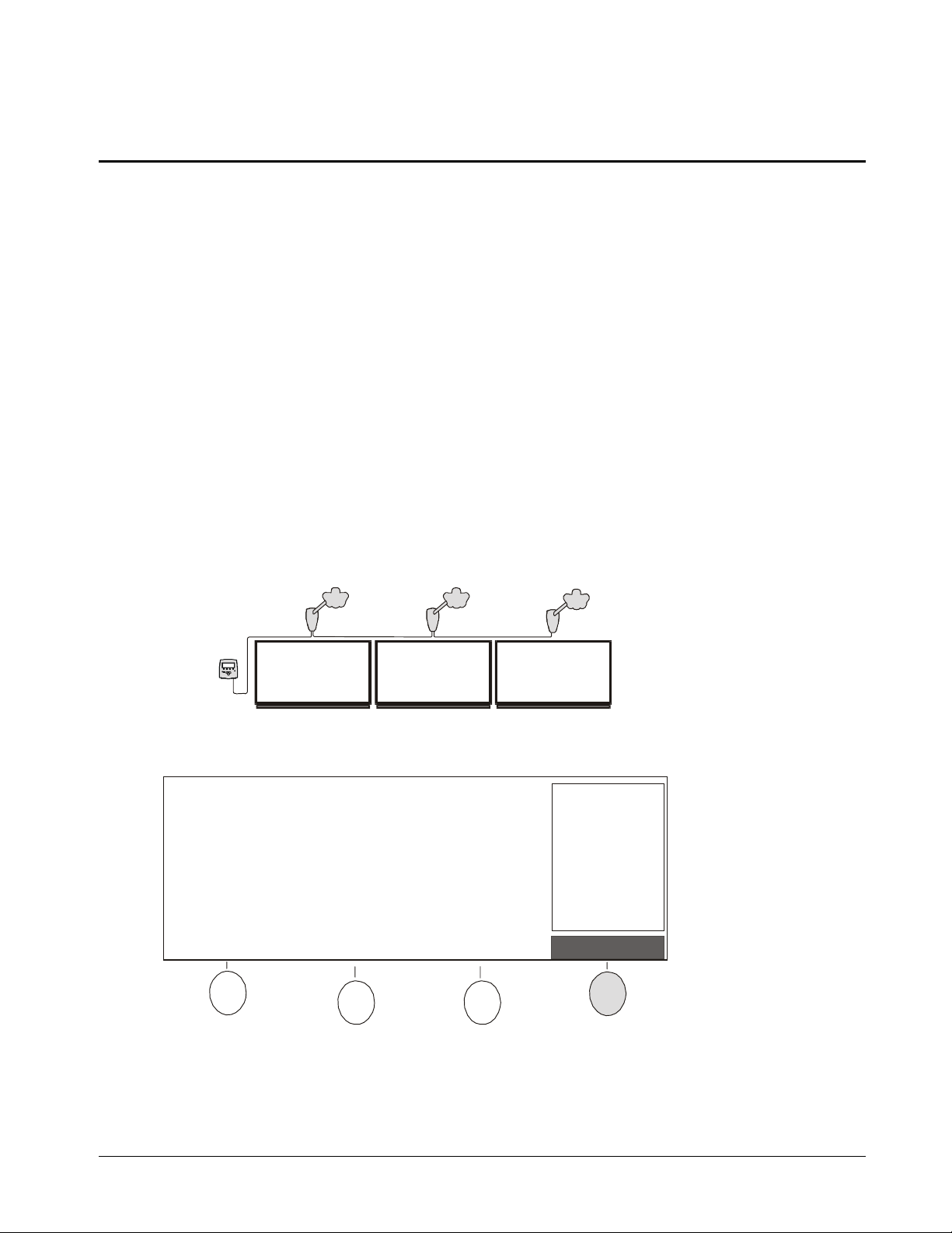
Multiple Camera Booms with a Control Unit
The procedure for installing a Hawkeye 480C system that captures notes from multiple
whiteboards is similar to the procedure for installing a system that captures notes from a
single whiteboard. However, when there are multiple whiteboards, you’ll need to install a
Camera Boom above each whiteboard, connect the Camera Booms to each other in a
daisy chain pattern and connect the last Camera Boom in the chain to the Control Unit.
: When you order additional Camera Booms for your Hawkeye 480C, you may
NOTE
receive the Hawkeye CAM Installation and User’s Guide. However, the information
included in that manual does not apply to your Hawkeye 480C.
Camera Boom
Control
Unit
: We recommend that you space whiteboards so that there is at least 12 ft (3.6 m)
NOTE
between the center of one whiteboard and the center of the next. The supplied IEEE 1394
cable is 15 ft (4.6 m) long.
Whiteboard
Multiple Camera Booms with a Control Unit
Unpacking and Checking Components
Unpack the contents of the shipping container, checking each item removed against the
following list. If any items are missing, contact SMART Technical Support.
•
a Camera Boom with a mounting template and wall bracket
•
a Control Unit with a mounting template and wall bracket
•
a universal power supply cable, with a country-specific attachment
•
an IEEE 1394 6-pin to 6-pin cable
•
Image-Saving Software CD-ROM
4
Installing the Camera Boom and Control Unit
Page 11

Recommended Tools
Have the following tools on hand when installing Hawkeye:
•
Phillips No. 2 screwdriver
•
bubble level
•
measuring tape
•
security hex-head Allen key (supplied)
Mounting a Camera Boom on the Wall
If you’re planning to use multiple Camera Booms, repeat these instructions for each one.
Step 1: Mark the drywall anchor locations
Measure the width of the whiteboard and use a pencil to mark on the wall the center
1
location of the whiteboard. Make the pencil mark immediately above the top edge of the
whiteboard.
Fold the Camera Boom template along the score line, making sure the fold is straight.
2
Rest the folded template on top of the whiteboard and use the diamond-shaped window
to align the template with the center mark above the whiteboard. Make sure that the
corner fold is snug against the wall and top edge of the whiteboard.
CAUTION
: There must be at least 17" (43 cm) clearance between the top of the
whiteboard and the ceiling.
Mark the center locations for the three drywall anchors.
3
Ceiling
Center of Whiteboard
17 (43 cm)
"
Minimum
Camera Boom
Te mp l at e
TM
Hawkeye Camera Alignment Template
WINDOW
1
STEP
STEP
121
Whiteboard
Drywall Anchor Location x 3
Alignment Window
Aligning the Camera Boom Template
Installing the Camera Boom and Control Unit
5
Page 12

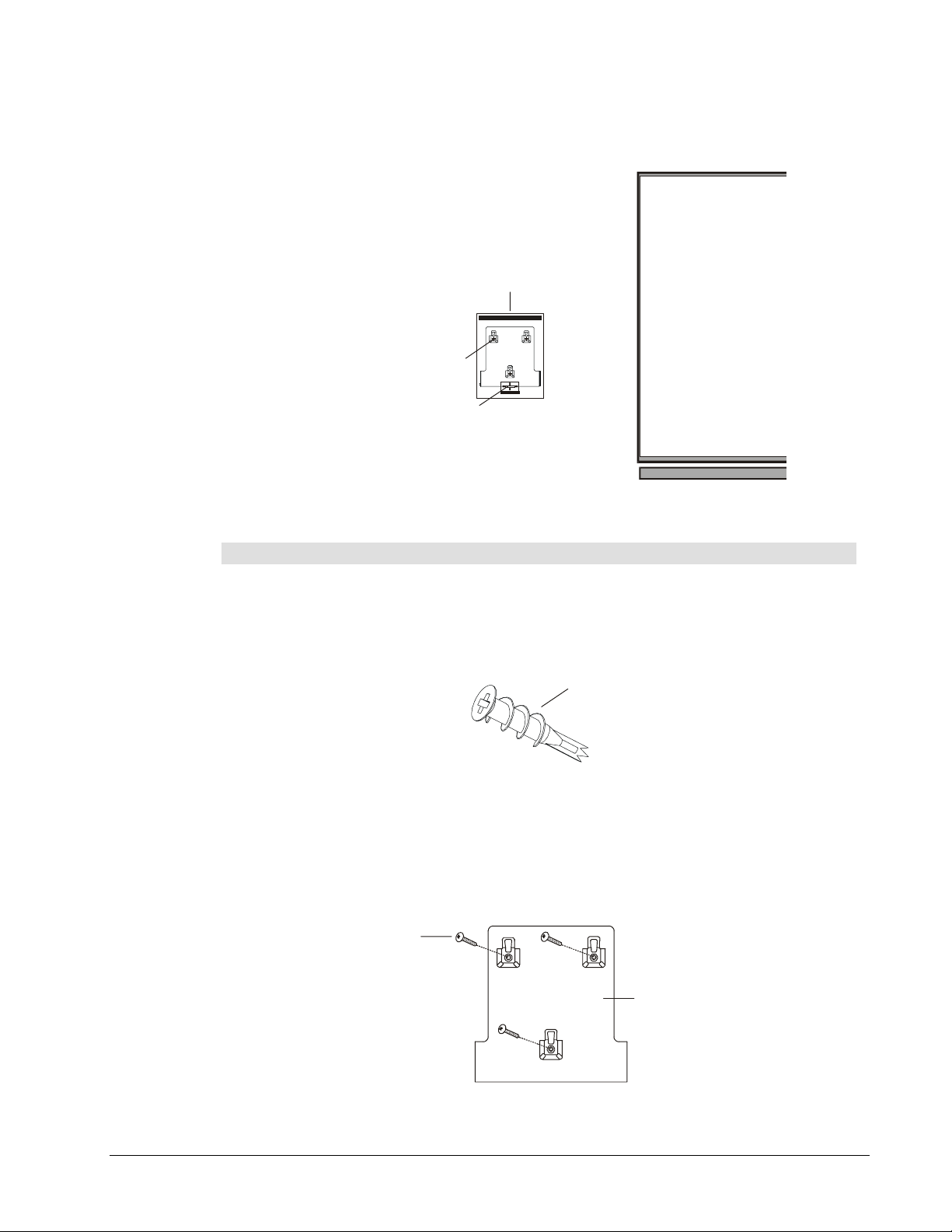
Step 2: Fasten the wall bracket to the wall
WARNING: DON’T USE A HAMMER TO FORCE THE E-Z TOGGLE DRYWALL
ANCHORS INTO THE WALL AS THIS COULD RESULT IN DAMAGE TO THE CAMERA
BOOM AND WALL SURFACE.
Using a Phillips No. 2 screwdriver, thread E-Z toggle drywall anchors into marked
1
locations that aren’t at a wall stud.
: The supplied drywall anchors are not suitable for walls thicker than 5/8" (1.59
NOTE
cm). If the wall is constructed of drywall thicker than 5/8" (1.59 cm), use non-toggle
drywall anchors for double-layer drywall.
If the marked location is at a wall stud, don’t use a drywall anchor. Use a No. 8 by 1.5"
(3.81 cm) long wood screw for wood studs or a self-drilling metal screw for metal studs.
Align the Camera Boom wall bracket with the drywall anchors. Insert screws into the
2
E-Z toggle drywall anchors as follows:
Press the screw firmly into the drywall anchor using the Phillips screwdriver until
a
approximately 1/3 of the screw remains.
Thread the remaining length of the screw into the drywall anchor until it’s tight. At
b
first the screw will thread with unusual ease, but it will gradually require greater
effort as the clamp inside the wall moves forward.
Screw x 3
Camera Boom
Wall Bracket
Fastening the Camera Boom Wall Bracket
Thread drywall anchor into wall
Press screw in until 1/3 remains
Thread remaining screw until tight
Using E-Z Toggle Drywall Anchors
6
Installing the Camera Boom and Control Unit
Page 13

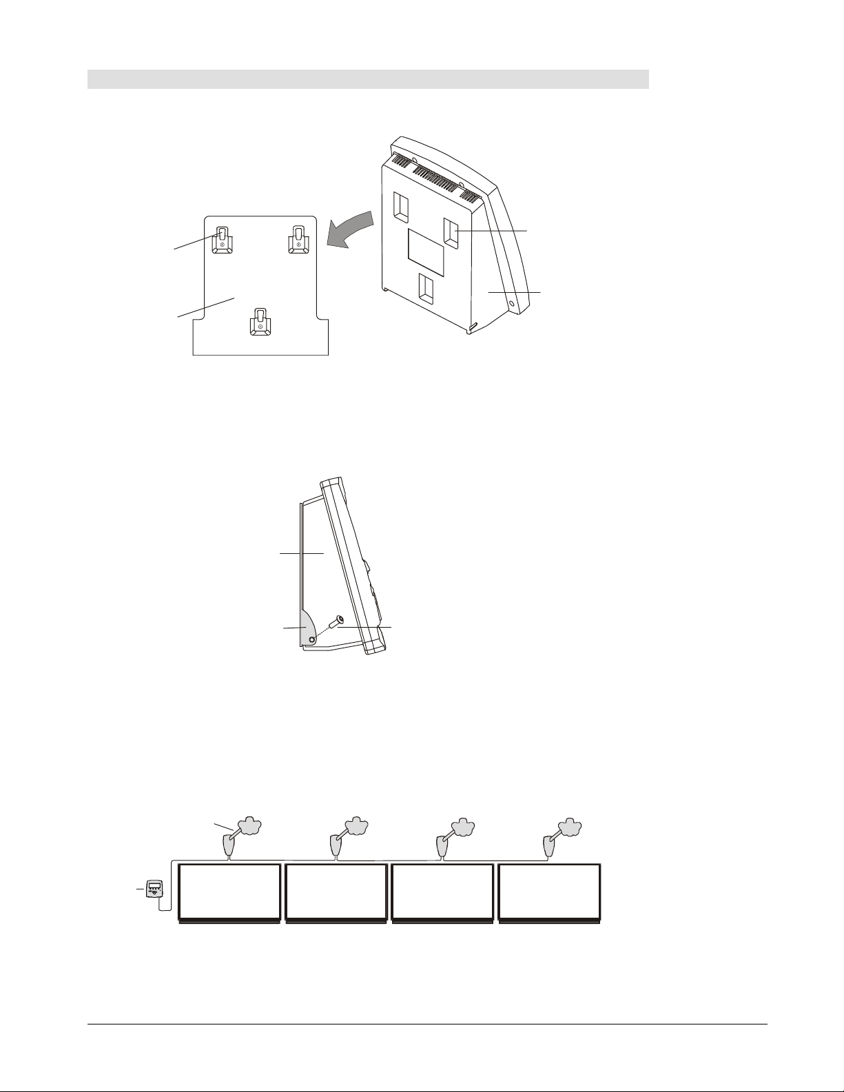
Step 3: Mount the Camera Boom on the wall
Lift the Camera Boom to the top of the wall bracket. Slide the base of the Camera Boom
1
onto the wall bracket, fitting the Camera Boom mounting slots onto the wall bracket
hooks.
Camera Boom
Hook x 3
Mounting Slot x 3
Camera Boom
Wall Bracket
Attaching the Camera Boom to the Wall Bracket
Lift the door open at the bottom of the Camera Boom base. Using the Allen key
2
provided, tighten the security hex screw at the bottom of the Camera Boom base. This
screw ensures the Camera Boom can’t be accidentally knocked free from its wall
bracket. It also helps prevent unauthorized people from taking the equipment.
Camera Boom Base
Door
Security Hex Screw
Tightening Security Hex Screw
Connecting Multiple Camera Booms
If you’re installing multiple Camera Booms to be used with one Control Unit, you’ll need to
connect the Camera Booms to each other in a daisy chain pattern. The information that will
be transmitted back and forth between the Control Unit and a Camera Boom will travel from
one Camera Boom to the next Camera Boom and so on until it reaches its destination.
Camera Boom
Bottom Edge of
Control Unit
Whiteboard
Daisy Chain Pattern
Installing the Camera Boom and Control Unit
7
Page 14

To connect multiple Camera Booms:
Begin with the Camera Boom furthest from the Control Unit.
1
Open the door at the bottom of the Camera Boom base. Insert the IEEE 1394 cable into
2
the IEEE 1394 port closest to the next Camera Boom.
Guide the IEEE 1394 cable through the wire management hook and close the door on
3
the Camera Boom base. Run the IEEE 1394 cable across the top of the whiteboard to
the next Camera Boom.
: You may want to use a raceway to keep the IEEE 1394 cable in position and out
NOTE
of the way. We recommend the LD Surface Raceway available in three sizes from the
Panduit Corporation. For more information, visit the Panduit Corporation Web site at
http://www.panduitncg.com/catalogs/catalogs.asp.
Second Camera Boom
IEEE 1394
Port
Wire
Management
Hook
First Camera Boom
IEEE 1394
Port
Wire
Management
Hook
IEEE 1394 Cable
Connecting Multiple Camera Booms
Open the door at the bottom of the next Camera Boom base. Insert the other end of the
4
IEEE 1394 cable into the IEEE 1394 port closest to the previous Camera Boom,
guiding the cable through the wire management hook.
Repeat steps 2 through 4 for each Camera Boom.
5
8
Installing the Camera Boom and Control Unit
Page 15
Mounting the Control Unit on the Wall
Step 1: Mark the drywall anchor locations
Select a position for the Control Unit that will enable people of varying body heights to
1
read information displayed on the Control Unit screen. Using a bubble level and pencil,
mark the center of the bottom edge of the Control Unit by drawing a cross hair on the
wall. We recommend you position the bottom edge of the Control Unit approximately
46" (116 cm) from the floor, and the center of the Control Unit at least 14" (35 cm) from
the edge of the whiteboard.
Control Unit Position
Whiteboard
NOTE:
Make sure the
line that marks
the bottom edge
of the Control
Unit is level.
Floor
Minimum
14 (35 cm)
"
Cross Hair
Approximately
46" (116 cm)
Positioning the Control Unit
Multiple Camera Booms are connected to one another in a daisy chain pattern. If you
plan on using multiple Camera Booms with one Control Unit, position the Control Unit
beside the last whiteboard in the chain. One Control Unit can be used with up to four
Camera Booms.
Camera Boom
Bottom Edge of
Control Unit
Whiteboard
Control Unit for Multiple Camera Booms
Installing the Camera Boom and Control Unit
9
Page 16
Using the rectangular window at the bottom of the template, align the Control Unit
2
template with the pencil mark you just made.
Mark the center locations for the three drywall anchors.
3
Control Unit Template
TM
Drywall Anchor Location x 3
Hawkeye Control Unit Alignment Template
2
STEP
STEP
2
1
STEP
STEP
2
1
2
STEP
STEP
!
WINDOW
Whiteboard
Alignment Window
Aligning the Control Unit Template
Step 2: Fasten the wall bracket to the wall
Using a Phillips No. 2 screwdriver, thread the drywall anchors for the Control Unit wall
1
bracket into marked locations that aren’t at a wall stud.
: If the marked location is at a wall stud, use a No. 8 by 1.5" (3.81 cm) long wood
NOTE
screw without a drywall anchor.
Drywall Anchor
Drywall Anchor for Control Unit Wall Bracket
Align the Control Unit wall bracket with the drywall anchors. Using the Phillips
2
screwdriver, thread screws into the three drywall anchors. Don’t over-tighten the
screws.
: If you plan to fasten screws to a steel wall stud, you must purchase appropriate
NOTE
self-drilling metal screws.
Screw x 3
Control Unit
Wall Bracket
10
Fastening the Control Unit Wall Bracket
Installing the Camera Boom and Control Unit
Page 17
Step 3: Mount the Control Unit on the wall
Lift the Control Unit to the top of the wall bracket. Slide the Control Unit onto the wall
1
bracket, fitting the Control Unit mounting slots onto the wall bracket hooks.
Mounting Slot x 3
Hook x 3
Control Unit
Control Unit
Wall Bracket
Attaching the Control Unit to the Wall Bracket
Using the Allen key provided, insert security hex screws into the two bottom corners of
2
the Control Unit. These screws ensure the Control Unit can’t be accidentally knocked
free from the wall bracket. They also help prevent unauthorized people from removing
the equipment.
Control Unit
Control Unit
Wall Bracket
Security Hex Screw x 2
Fastening the Security Hex Screws
Connecting a Camera Boom to the Control Unit
If you’re installing multiple Camera Booms, you only need to connect the last Camera Boom
in the daisy chain pattern to the Control Unit. The information that will be transmitted back
and forth between the Control Unit and a Camera Boom will travel from one Camera Boom
to the next and so on until it reaches its destination.
Camera Boom
Control
Unit
Whiteboard
Control Unit with Multiple Camera Booms
Installing the Camera Boom and Control Unit
11
Page 18
To connect a Camera Boom to the Control Unit:
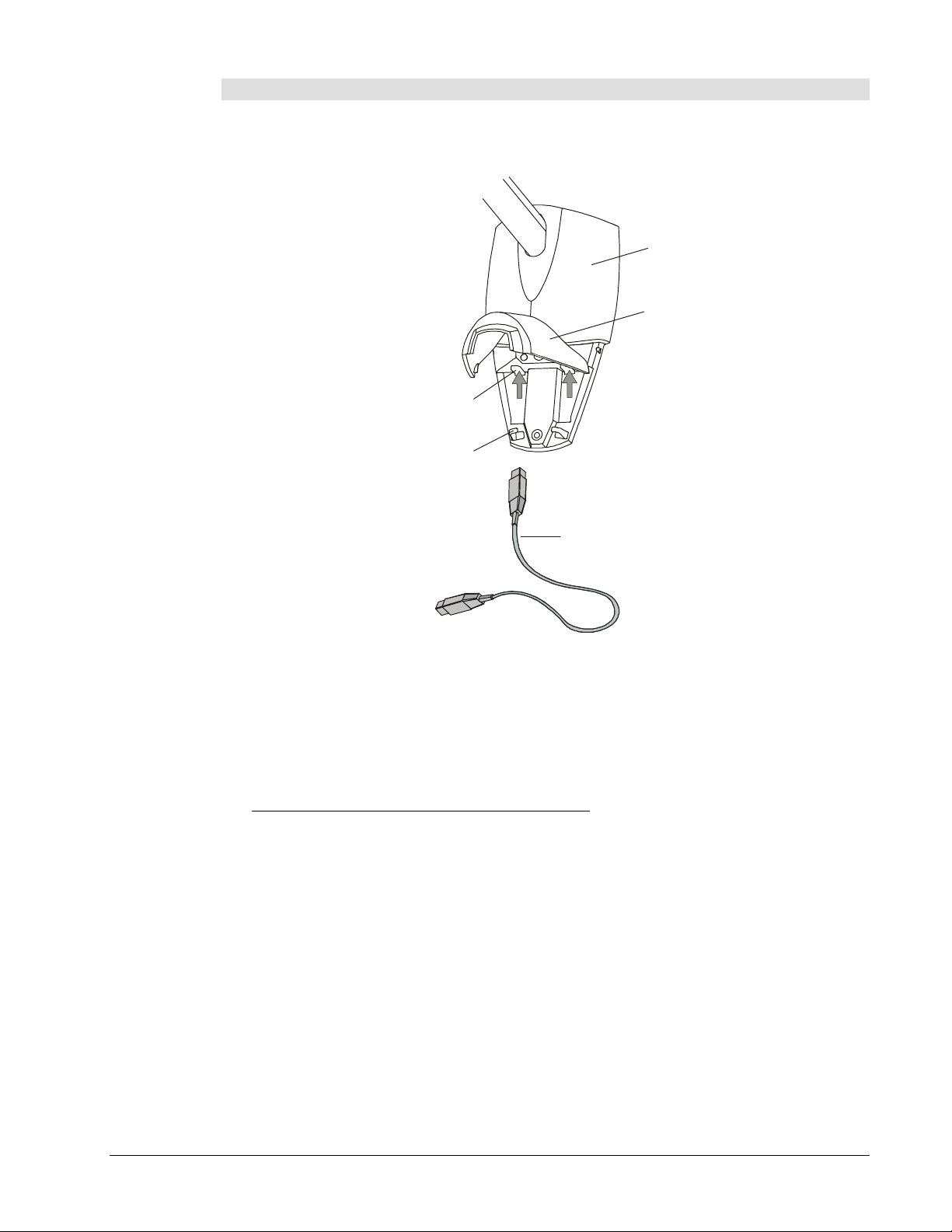
Open the door at the bottom of the Camera Boom base. Insert the IEEE 1394 cable into
1
the IEEE 1394 port closest to the Control Unit.
Camera Boom Base
Door
IEEE 1394 Port x 2
Wire Management Hook x 2
IEEE 1394 Cable
Connecting the IEEE 1394 Cable to the Camera Boom
Guide the IEEE 1394 cable through the wire management hook and close the door on the
2
Camera Boom base. Run the IEEE 1394 cable across the top and down the side of the
whiteboard, and then along the wall towards the Control Unit.
: You may want to keep the IEEE 1394 cable in position and out of the way by using
NOTE
a raceway. We recommend the LD Surface Raceway available in three sizes from the
Panduit Corporation. For more information, visit the Panduit Corporation Web site at
http://www.panduitncg.com/catalogs/catalogs.asp.
Insert the other end of the IEEE 1394 cable into the IEEE 1394 port underneath the
3
Control Unit.
12
Installing the Camera Boom and Control Unit
Page 19

IEEE 1394 Port
IEEE 1394 Cable
To C a me r a Bo o m
Connecting the IEEE 1394 Cable to the Control Unit
Bottom View of
Control Unit
Installing the Camera Boom and Control Unit
13
Page 20

Configuring a Stand-Alone Control Unit
To configure a Control Unit that won’t be connected to a network, you’ll need to:
Connect the Control Unit to a printer (page 14).
1
Connect the Control Unit to a power source (pages 15–16).
2
Specify the type of printer (pages 17–18).
3
Connecting the Control Unit to a Local Printer
Insert one end of the printer cable into the parallel port on the bottom of the Control
1
Unit.
Bottom View of
Control Unit
Parallel
Printer Port
Printer Cable
Connecting the Printer Cable
Insert the other end of the printer cable into the parallel port on the printer.
2
To Printer
14
Configuring a Stand-Alone Control Unit
Page 21
Connecting the Control Unit to a Power Source
: Don’t connect the Control Unit to a power source until you’ve connected the IEEE
NOTE
1394 and printer cables.
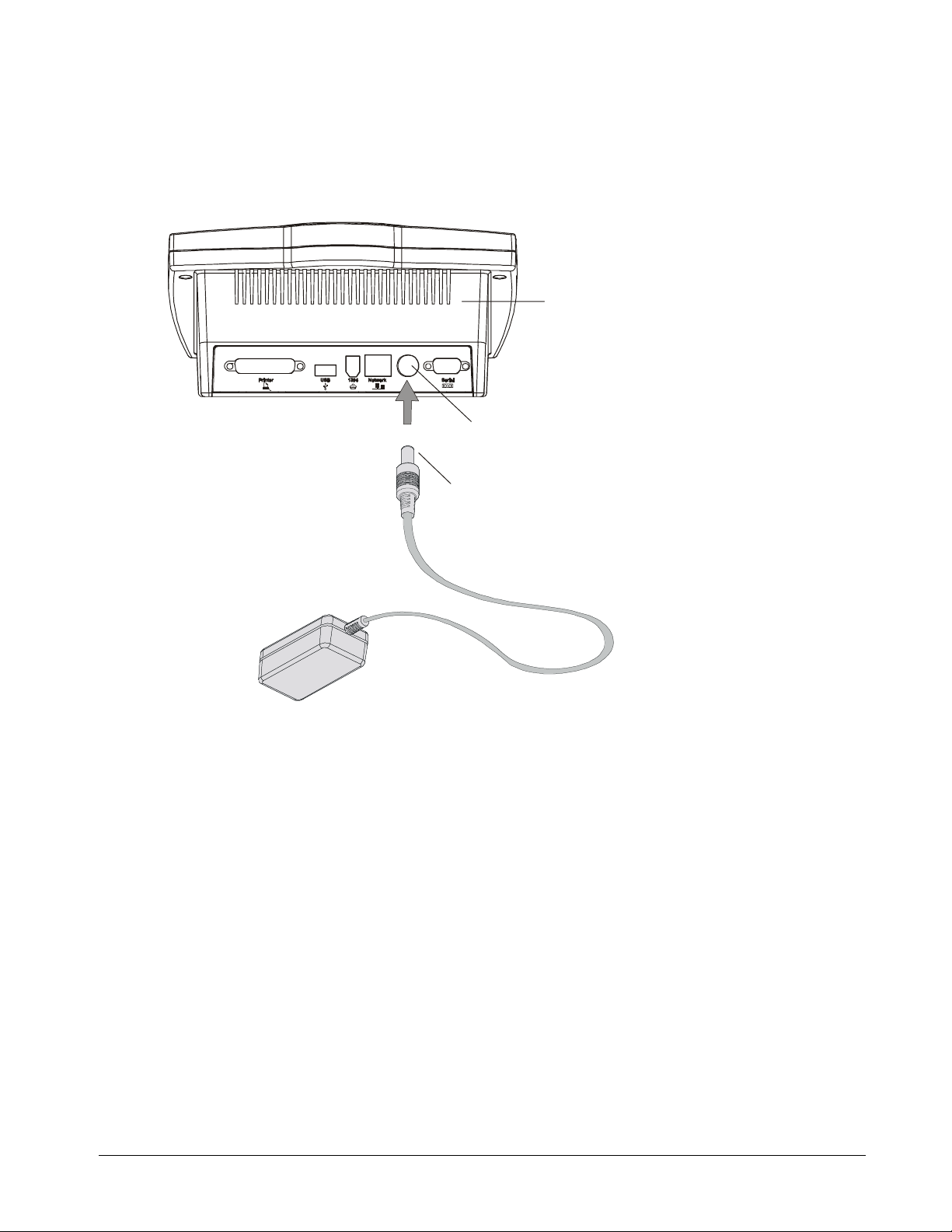
Insert the barrel-shaped connector end of the universal power supply cable into the
1
power socket underneath the Control Unit.
Bottom View of
Control Unit
Power Socket
Barrel-Shaped Connector End of
Universal Power Supply Cable
Connecting the Universal Power Supply Cable to the Control Unit
Configuring a Stand-Alone Control Unit
15
Page 22

Connect the female end of the country-specific power cable to the male (pronged) end of
2
the universal power cable.
To Control Unit
Central Europe (Germany)
Japan
United Kingdom (Ireland)
Male End of Universal
Power Supply Cable
Australia (New Zealand)
Female End of CountrySpecific Power Cable
North America
Universal Power Supply Cable
Plug the male (pronged) end of the country-specific power cable into an electrical power
3
Country-Specific Power Cables
outlet. The power indicator light will turn green immediately and the following screen will
appear on the Control Unit within a couple of minutes.
Initial Screen
Scroll
Close Se ssionOpen Sessi on
Power Indicator
Light
16
Capture
Control Unit Initial Screen
Configuring a Stand-Alone Control Unit
Page 23

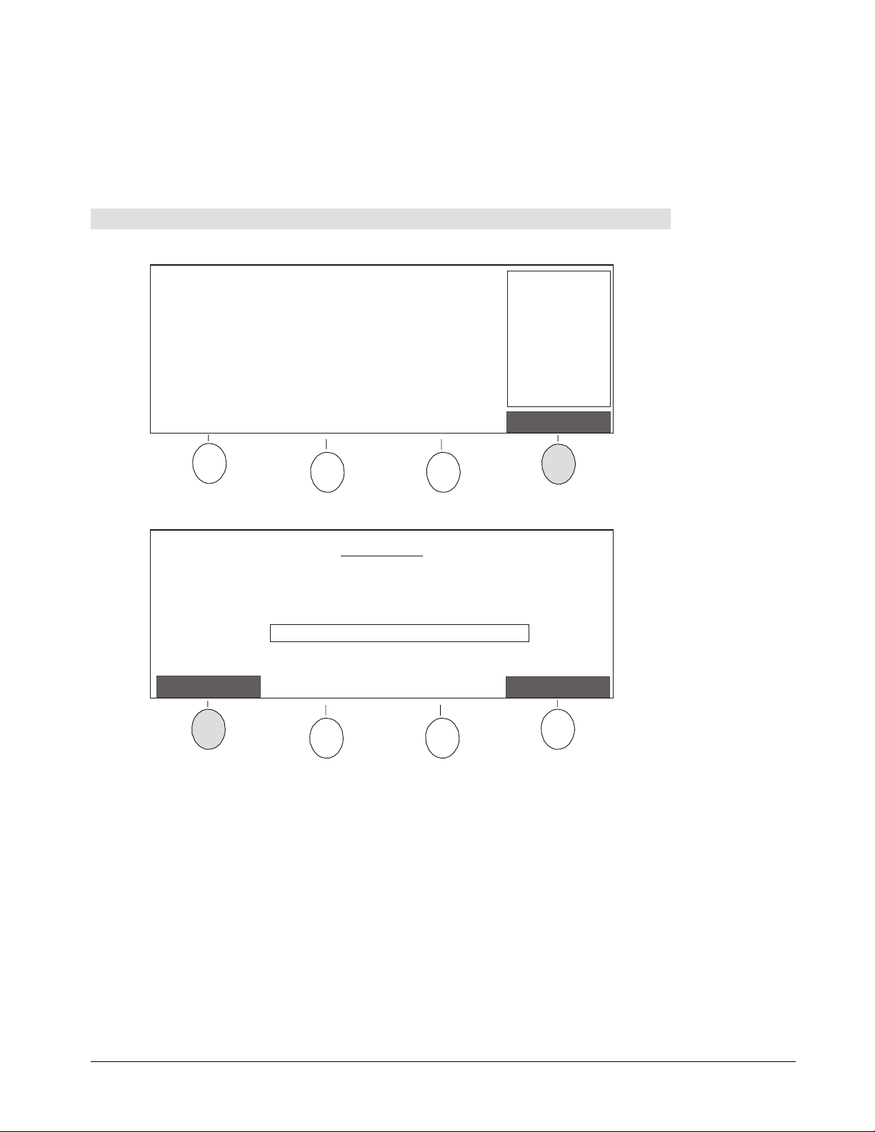
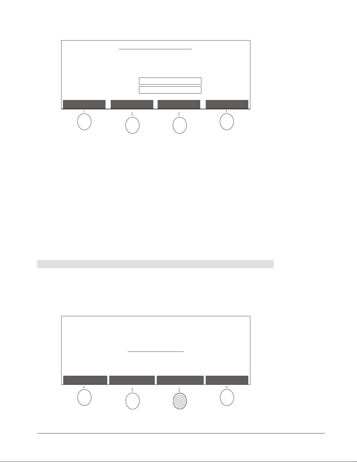
Specifying a Local Printer Type
The Control Unit includes two types of buttons: those reserved for specific functions and those
assigned as needed. Buttons that can be assigned are referred to as soft buttons. The current
function of each soft button is identified on the Control Unit screen.
To begin specifying the printer type, you’ll need to use the Options soft button.
No session is active.
Press Open Session to begin.
IP Addr ess is:
192.168.1.10
or hawk setup
Options
Control Unit Screen
Options Soft Button
Scroll
Open Sessi on
Close Se ssion
Capture
Power Indicator
Light
Scroll Buttons
Capture Button
Control Unit Configuration Buttons
To specify the type of printer connected to the Control Unit:
Press the Options button on the Control Unit.
1
No session is active.
Press Open Session to begin.
IP Address is:
192.168.1.10
or hawksetup
Options
Configuring a Stand-Alone Control Unit
17
Page 24

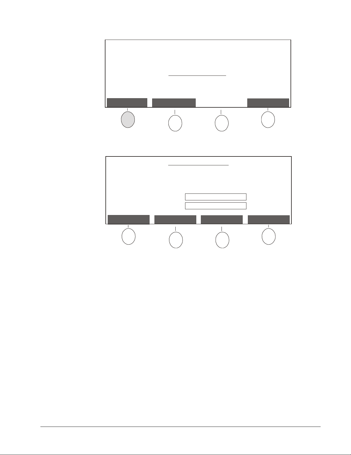
The Options Mode screen will appear.
Options Mode
* Use Scroll buttons to select an Option.
* Press Continue when done.
Option: Configure Local Printer
Hawkeye 480C 1.0.17
Continue
Use the Scroll buttons to select the
2
Configure Local Printer
Return
option and press the
Continue button.
The following screen will appear.
* Use Scroll buttons to select a printer
manufacturer.
* Press Continue when done.
IP Address is:
Printer Manufacturer: Canon
Use the Scroll buttons to select a printer manufacturer and press the Continue button.
3
192.168.1.10
or hawksetup
ReturnContinue
18
If many printers created by the manufacturer you selected are supported, you’ll be
4
prompted to select a printer model before you select a printer type. Use the Scroll
buttons to select a printer model and then press the Continue button.
The following screen will appear to allow you to select a printer type.
* Use Scroll buttons to select a printer.
* Press Save when done.
IP Address is:
Printer: Canon BJC 1000
Use the Scroll buttons to select a printer and press the Save button.
5
192.168.1.10
or hawksetup
CancelSave
Configuring a Stand-Alone Control Unit
Page 25

Configuring a Networked Control Unit
It’s easier to share the information captured from your whiteboard when your Control Unit is
connected to a network. When the Control Unit has a network connection, you can use the
Image-Saving Software to automatically save every image captured at the Control Unit to a
computer within the same network. With a network connection, current images are also
immediately available by opening a Web browser to the IP address or Host Name of the
Control Unit.
This section explains how to configure a Control Unit that will be connected to a network.
For information about configuring a Control Unit that won’t be used with a network, refer to
pages 14–18.
The procedure for configuring a networked Control Unit varies, depending on whether IP
addresses are assigned dynamically by the DHCP (Dynamic Host Configuration Protocol) or
manually by a systems administrator using Static IP.
DHCP Network
To configure a Control Unit that will be used on a DHCP network, you’ll need to perform the
following four tasks:
Connect the Control Unit to the network (page 20).
1
Connect the Control Unit to a power source (pages 21–22).
2
Change network settings using the Control Unit (pages 25–28) or a Web browser
3
(page 30–31).
If you want to print captured images to a network printer while working at the
4
whiteboard, select a network printer using the Control Unit (page 31–33) or a Web
browser (page 34).
Static IP Network
To configure a Control Unit that will be used on a Static IP network, you’ll need to perform
the following four tasks:
Connect the Control Unit to a power source (pages 21–22).
1
Change network settings using the Control Unit (pages 25–28).
2
Connect the Control Unit to the network (page 20).
3
If you want to print captured images to a network printer while working at the
4
whiteboard, select a network printer using the Control Unit (page 31–33) or a Web
browser (page 34).
Configuring a Networked Control Unit
19
Page 26

Connecting the Control Unit to a Network
: If your network uses Static IP addresses, you don’t need to connect the Control Unit
NOTE
to the main network until you’ve finished configuring the Control Unit. For more information,
refer to the list of tasks required for a Static IP network on the previous page.
Insert one end of the main network cable into the network port underneath the Control
1
Unit. The network cable is usually blue.
Bottom View of
Control Unit
Network Port
Network Cable
Connecting the Network Cable
Insert the other end of the network cable into a wall network socket.
2
To Wal l
Network Socket
20
Configuring a Networked Control Unit
Page 27
Connecting the Control Unit to a Power Source
: If your network uses DHCP, make sure that you connect the IEEE 1394 and
NOTE
network cables before you connect a power source.
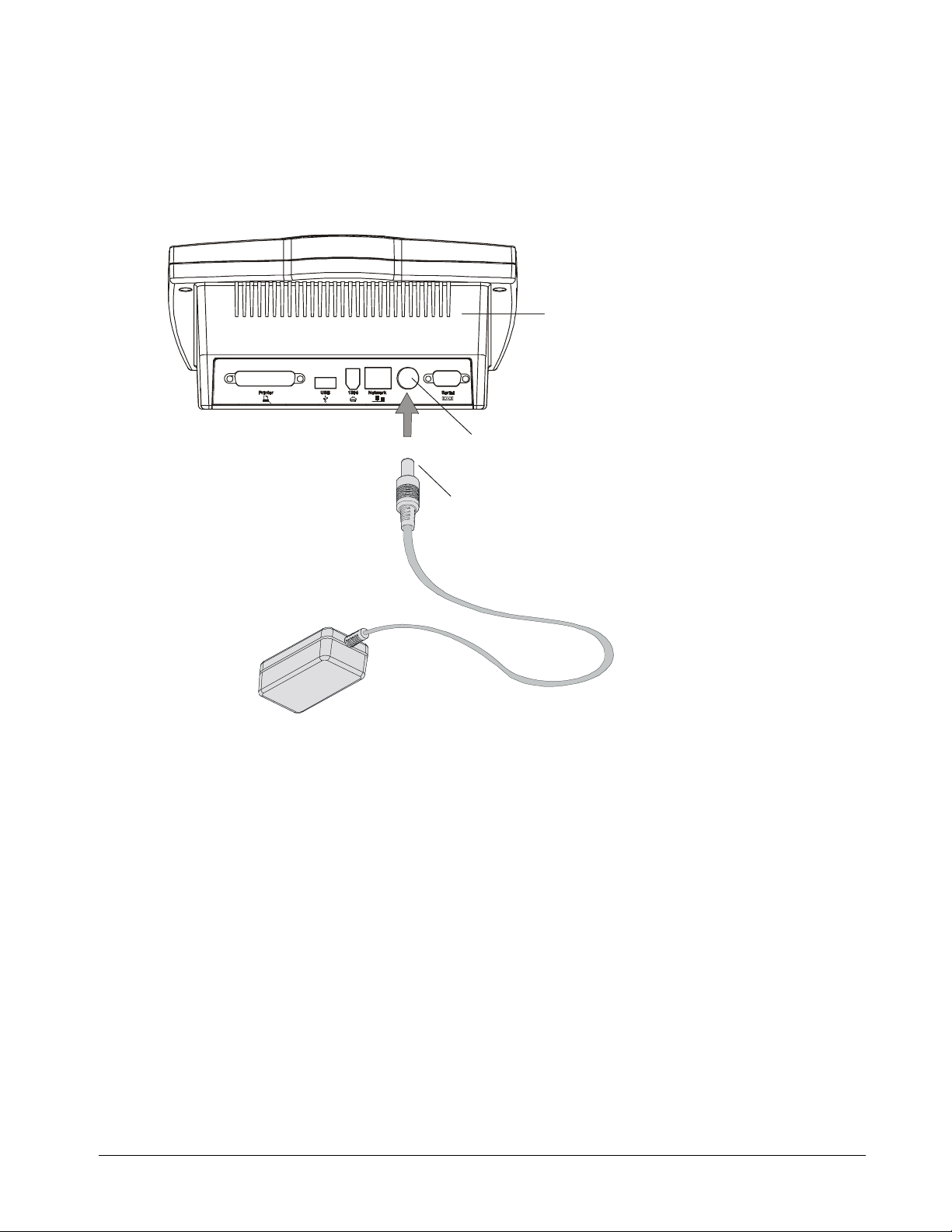
Insert the barrel-shaped connector end of the universal power supply cable into the
1
power socket underneath the Control Unit.
Bottom View of
Control Unit
Power Socket
Barrel-Shaped Connector End of
Universal Power Supply Cable
Connecting the Universal Power Supply Cable to the Control Unit
Configuring a Networked Control Unit
21
Page 28

Connect the female end of the country-specific power cable to the male (pronged) end
2
of the universal power cable.
To Control Unit
Central Europe (Germany)
Japan
United Kingdom (Ireland)
Male End of Universal
Power Supply Cable
Australia (New Zealand)
Female End of CountrySpecific Power Cable
North America
Universal Power Supply Cable
Plug the male (pronged) end of the country-specific power cable into an electrical power
3
Country-Specific Power Cables
outlet. The power indicator light will turn green immediately and the following screen will
appear on the Control Unit within a couple of minutes.
Initial Screen
Scroll
Close Se ssionOpen Sessi on
Power Indicator
Light
22
Capture
Control Unit Initial Screen
Configuring a Networked Control Unit
Page 29
Configuring Network Settings at the Control Unit
If your network uses DHCP, you can configure network settings at the Control Unit or on a
computer using a Web browser. However, if your network uses Static IP addresses, you’ll
probably want to configure network settings at the Control Unit. Configuring Static IP
network settings at the Control Unit is easier than the alternative, which involves
reconfiguring a computer connected directly to the Control Unit.
To access the Admin functions:
Press the Options button on the Control Unit.
1
No session is active.
Press Open Session to begin.
IP Address is:
192.168.1.10
or hawksetup
Options
The Options Mode screen will appear.
* Use Scroll buttons to select an Option.
* Press Continue when done.
Option: Configure Network Settings Login
Continue
Use the Scroll buttons to select the
2
press the Continue button.
Options Mode
Hawkeye 480C 1.0.17
Configure Network Settings Login
Return
option and
Configuring a Networked Control Unit
23
Page 30

The Admin Login Mode screen will appear.
Admin Login Mode
* Use Scroll buttons to select characters.
* Press Next Character to move ahead one space.
* Press Submit when done.
Admin Password:
Current Character Set: a-z
CancelNext CharacterCharacter SetSubmit
If this is the first time that you’ve accessed Admin functions, leave the Password blank.
3
Otherwise, enter a password as follows:
If you want to use a different set of characters, continue pressing the Character Set
a
button until you find the one you want. You can only use letters and numbers in the
password. Special symbols are not supported.
: To delete a character, select the
NOTE
Character Set, position the cursor
delete
under the character you want to remove and press the right Scroll button. If you
continue pressing the Next Character button beyond the end of a field, the cursor
will return to the first character in the field, thereby enabling you to position the
cursor under the character you want to delete.
Use the Scroll buttons to select each character and press the Next Character
b
button to move ahead one space.
When you’re finished entering a password, press the Submit button.
c
The Admin Functions Mode screen will appear.
To change the Admin password:
Press the Admin Password button in the Admin Functions Mode screen. For
1
information about accessing this screen, refer to pages 23–24.
Admin Functions Mode
ReturnNetwork SettingsTime/DateAdmin Password
24
Configuring a Networked Control Unit
Page 31
The Change Admin Password Mode screen will appear.
Change Admin Password Mode
* Use the Scroll buttons to select characters.
* Press Next Character to move ahead one space.
* Press Submit when done.
New Admin Password:
Current Character Set: a-z
CancelNext CharacterCharacter SetSubmit
If you want to use a different set of characters, continue pressing the Character Set
2
button until you find the one you want. You can only use letters and numbers in the
password. Special symbols are not supported.
Use the Scroll buttons to select each character and press the Next Character button to
3
move ahead one space.
: To delete a character, select the
NOTE
Character Set, position the cursor
delete
under the character you want to remove and press the right Scroll button. If you
continue pressing the Next Character button beyond the end of a field, the cursor will
return to the first character in the field, thereby enabling you to position the cursor
under the character you want to delete.
When you’re finished entering a password, press the Submit button.
4
A message will appear indicating that the admin password has been changed
successfully.
Press the Return button.
5
To configure network settings:
You can determine whether your network uses Static IP or DHCP by checking the IP
Address that appears on the right side of the Control Unit screen. If the IP Address is
“192.168.1.10”, then your network uses Static IP; otherwise it uses DHCP. Consult with
your system administrator if you’re not sure.
Press the Network Settings button in the Admin Functions Mode screen. For
1
information about how to access this screen, refer to pages 23–24.
Admin Functions Mode
ReturnNetwork SettingsTime/DateAdmin Password
Configuring a Networked Control Unit
25
Page 32
The following screen will appear.
Press the Network button.
2
The following screen will appear.
* Use Scroll buttons to select characters.
* Press Next Character to move ahead one space.
* Press Continue when done.
Control Unit Host Name: hawksetup
Current Character Set: a-z
Network Settings Mode
ReturnNetwork PrinterNetwork
Configure Network Mode
ReturnNext CharacterCharacter SetContinue
Change the default host name assigned to your Control Unit during manufacturing. You
3
may want to use a name that identifies the room where the Control Unit is installed.
The maximum number of characters allowed in the host name is 15 and the factory
default name is “hawksetup”:
If you want to use a different set of characters, continue pressing the Character Set
a
button until you find the one you want. You can only use letters and numbers in the
host name. Special symbols are not supported.
Use the Scroll buttons to select each character and press the Next Character
b
button to move ahead one space.
: To delete a character, select the
NOTE
Character Set, position the cursor
delete
under the character you want to remove and press the right Scroll button. If you
continue pressing the Next Character button beyond the end of a field, the cursor
will return to the first character in the field, thereby enabling you to position the
cursor under the character you want to delete.
When you’re finished entering the host name, press the Continue button.
c
26
Configuring a Networked Control Unit
Page 33

The following screen will appear.
Configure Network Mode
* Use Scroll buttons to select the network type.
* Press Continue when done.
Network Type: dhcp
Continue
Use the Scroll buttons to select
4
dhcp
or
static
as the
Network Type
Return
and press the
Continue button.
The following screen will appear if you selected
Configure Network Mode
* Use Scroll buttons to select a value.
* Press Next Field to move ahead one field.
* Press Continue when done.
IP Address: 000 . 000 . 000 . 000
Netmask: 000 . 000 . 000 . 000
If you’re configuring DHCP network settings, skip this step. If you’re configuring Static
5
IP network settings, input the
IP Address
of the Control Unit and the
static
.
ReturnNext FieldPrevious FieldContinue
Netmask
:
Use the Next Field and Previous Field buttons to navigate to the field and select a
a
value using the Scroll buttons. If you don’t want to configure a field, leave it
displaying all zeros.
When you’ve finished changing fields, press the Continue button.
b
The following screen will appear.
Configure Network Mode
* Use Scroll buttons to select a value.
* Press Next Field to move ahead one field.
* Press Submit when done.
Wins Server: 000 . 000 . 000 . 000
DNS Server: 000 . 000 . 000 . 000
Gateway: 000 . 000 . 000 . 000
Next FieldPrevious FieldSubmit
Cancel
Configuring a Networked Control Unit
27
Page 34

6
Input the
a
Wins Server, DNS Server
Use the Next Field and Previous Field buttons to navigate to the field and select a
and
Gateway
:
value using the Scroll buttons. If you don’t want to configure a field, leave it
displaying all zeros.
Press the Submit button when you’ve finished changing the fields.
b
A message will appear indicating that network settings were configured
successfully.
Press the Restart button and the Control Unit will be restarted.
7
To change the Control Unit date and time:
Before you begin capturing notes on your whiteboard, you’ll need to adjust the date and
time on your Control Unit. You’ll also need to use this feature if you live in an area that
undergoes regular time changes for daylight savings.
Press the Time/Date button in the Admin Functions Mode screen. For information
1
about how to access this screen, refer to pages 23–24.
Admin Functions Mode
ReturnNetwork SettingsTime/DateAdmin Password
The Configure Time/Date Mode screen will appear.
Configure Time/Date Mode
* Use Scroll buttons to select a value.
* Press Next Field to move ahead one field.
* Press Submit when done.
Time (24Hrs clock - hr:min): 13:02
Date (dd/mm/yyyy): 18/08/2000
Next Field
Review the date and time settings displayed on the Control Unit screen. To change a
2
CancelPrevious FieldSubmit
field, use the Next Field and Previous Field buttons to navigate to the field you want to
change and then select a value using the Scroll buttons.
Press the Submit button when you’ve finished changing the fields.
3
A message will appear when the date and time has been changed.
Press the Return button.
4
28
Configuring a Networked Control Unit
Page 35
Configuring Network Settings Using a Web Browser
If you have a network that uses DHCP, you can use the Control Unit or a Web browser on a
computer to configure network settings. However, if you have a network that uses Static IP,
you’ll need to configure network settings at the Control Unit. Refer to pages 25–28 for
instructions on using the Control Unit to configure network settings.
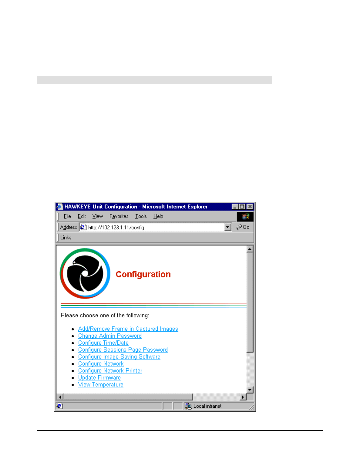
To access the Configuration Web page:
Open a Web browser, such as Microsoft Internet Explorer or Netscape Communicator,
1
on a computer connected to the same network as the Control Unit.
You can determine whether your network uses DHCP by checking the IP Address that
appears on the right side of the Control Unit screen. If the IP Address is any number
other than “192.168.1.10”, then your network uses DHCP. Consult with your system
administrator if you’re not sure.
Enter the
screen, plus “/config” in the
Address of your Control Unit was “102.123.1.11”, you’d enter 102.123.1.11/config”. You
can only use letters and numbers in the Host Name. Special symbols are not supported.
The Enter Network Password dialog box will appear.
Enter “admin” as the
2
Configuration page, leave the
you assigned and click OK.
The Configuration page will appear.
IP Address
or
Host Name
Address
User Name
Password
that appears on the right side of the Control Unit
box in the Web browser. For example, if the IP
. If this is the first time you’ve accessed the
blank. Otherwise, enter the
Password
that
Configuring a Networked Control Unit
29
Page 36

To change the Admin Password:
Click
1
2
3
4
Change Admin Password
accessing this Web page, refer to page 29.
The Change Admin Password page will appear.
Enter a
recommend that you write down the password and keep the information in a safe place.
NOTE
supported.
Click the Submit Password button.
The Changing Admin Password page will appear.
Click
New Password
: You can only use letters and numbers in the password. Special symbols are not
Back to Configuration page
and re-type your password in the
in the Configuration page. For information about
Confirm Password
.
field. We
To assign a password to the Sessions page:
: By default, a password is not required to access captured images on the Sessions
NOTE
page. If you would like to control who can view captured images, complete the following
procedure.
Click
1
2
3
4
5
6
Configure Sessions Page Password
about accessing this Web page, refer to page 29.
The Configure Sessions Page Password page will appear.
Select the
Enter a
recommend that you write down the password and keep the information in a safe place.
NOTE
supported.
Click the Submit Password button.
The Configuring Sessions Page Password page will appear.
Click
Don’t forget to tell the password to people who need to access the captured images.
Enable Sessions Page Password
New Password
: You can only use letters and numbers in the password. Special symbols are not
Back to Configuration page
and re-type your password in the
.
in the Configuration page. For information
checkbox.
Confirm Password
To configure DHCP network settings:
Click
1
2
Configure Network
this Web page, refer to page 29.
The Configure Network page will appear.
Change the default
during manufacturing. You may want to use a name that identifies the room where the
Control Unit is installed. The factory default Host Name is “hawksetup”.
in the Configuration page. For information about accessing
Host Name
(maximum 15 characters) assigned to your Control Unit
field. We
30
: You can only use letters and numbers in the
NOTE
not supported.
Review the settings of the other fields displayed in the Configure Network page and
3
make changes as needed.
Click the Submit Configuration button.
4
The Validating Network Configuration page will appear.
Configuring a Networked Control Unit
Host Name
. Special symbols are
Page 37

Review the network settings displayed in the Validating Network Configuration page. If
5
you’re satisfied with the settings, click the Set Configuration button. Otherwise, click the
Go Back button to return to the Configure Network page.
A Web page will appear indicating that the configuration files are being updated and the
Control Unit will be restarted.
: If your network uses a naming service, it may take awhile for a new
NOTE
to come into effect. If you experience difficulties reconnecting to the Configuration or
Sessions page using a new
Host Name
, try using the
IP Address
instead.
Host Name
To change the Control Unit date and time:
Before you begin capturing the notes on your whiteboard, you’ll need to adjust the date and
time on your Control Unit. You’ll also need to use this feature if you live in an area that
undergoes regular time changes for daylight savings.
Click
1
2
3
4
5
Configure Time/Date
this Web page, refer to page 29.
The Time/Date Configuration page will appear.
Enter the
Click the Submit Time/Date button.
The Validating Time/Date Configuration page will appear.
Review the time and date settings. If you’re satisfied with the settings, click the Set
Time/Date button. Otherwise, click the Go Back button to return to the Time/Date
Configuration page.
Click
Back to Configuration page
Time
and
Date
in the Configuration page. For information about accessing
that you want.
.
To view the current temperature of the Control Unit:
Click
View Temperature
Web page, refer to page 29. The Temperature page will appear.
in the Configuration page. For information about accessing this
Specifying a Network Printer at the Control Unit
: Hawkeye 480C only supports postscript TCP/IP network printers.
NOTE
Press the Network Settings button in the Admin Functions Mode screen. For
1
information about how to access this screen, refer to pages 23–24.
Admin Functions Mode
Configuring a Networked Control Unit
ReturnNetwork SettingsTime/DateAdmin Password
31
Page 38

The Network Settings Mode screen will appear.
Network Settings Mode
Press the Network Printer button.
2
The first screen for specifying a network printer will appear.
Configure Postscript TCP/IP Network Printer Mode (step 1 of 3)
* Press IP/Port to specify printer IP and port number.
* Press IP/Queue to specify printer IP and queue name.
ReturnNetwork PrinterNetwork
ReturnIP/QueueIP/Port
If your postscript TCP/IP printer is set up to receive jobs at a port, press the IP/Port
3
button.
Or
If your postscript TCP/IP printer is set up to receive jobs at a queue, press the
IP/Queue button.
The following screen will appear.
Configure Postscript TCP/IP Network Printer Mode (step 2 of 3)
* Use Scroll buttons to select a value.
* Press Next Field to move ahead one field.
* Press Continue when done.
Printer IP: 000 . 000 . 000 . 000
Next Field
ReturnPrevious FieldContinue
32
Use the Scroll buttons to select a value for each field in the
4
the Next Field button to move ahead one field.
Configuring a Networked Control Unit
Printer IP
and then press
Page 39
When you’re finished defining the IP Address, press the Continue button.
5
If you selected IP/Port earlier, the following screen will appear.
Configure Postscript TCP/IP Network Printer Mode (step 3 of 3)
* Use Scroll buttons to select characters.
* Press Next Character to move ahead one space.
* Press Submit when done.
Remote Printer Port <e.g. 9100>:
Current Character Set: 0-9
Submit
Character Set
Next Character
If you selected IP/Queue earlier, this screen will appear.
Configure Postscript TCP/IP Network Printer Mode (step 3 of 3)
* Use Scroll buttons to select characters.
* Press Next Character to move ahead one space.
* Press Submit when done.
Remote Printer Queue <e.g. raw>:
Current Character Set: a-z
6
Specify a
Character Set
Remote Printer Port
by using the Scroll buttons to select each character and
Next Character
pressing the Next Character button to move ahead one space.
Or
Cancel
CancelSubmit
Specify a
Remote Printer Queue
by using the Scroll buttons to select each character
and pressing the Next Character button to move ahead one space.
If you want to use a different set of characters, continue pressing the Character Set
button until you find the one you want. If you make a mistake and need to delete a
character, select the
Character Set, position the cursor under the character you
delete
want to remove and press the right Scroll button. If you continue pressing the Next
Character button beyond the end of a field, the cursor will return to the first character in
the field, thereby enabling you to position the cursor under the character you want to
delete.
Press the Submit button.
7
A message will appear indicating that the network printer has been configured
successfully.
Press the Return button.
8
Configuring a Networked Control Unit
33
Page 40

Specifying a Network Printer Using a Web Browser
: Hawkeye 480C only supports postscript TCP/IP network printers.
NOTE
Open a Web browser on a computer that is networked to the Control Unit.
1
Enter the
2
Address
For example, if the IP Address of your Control Unit is “102.123.1.11”, you’d enter
“http://102.123.1.11/config”.
The Enter Network Password dialog box will appear.
Enter “admin” as the
3
Configuration page, leave the
Password
Click OK.
4
The Configuration page will appear.
Click
5
The Configure Network Printer page will appear.
Enter the
6
Click the Submit Configuration button.
7
The Validating Network Printer Configuration page will appear.
Review the network printer settings. If you’re satisfied with the settings, click the Set
8
Configuration button. Otherwise, click the Go Back button to return to the Configure
Network Printer page.
Click
9
IP Address
box in the Web browser.
.
Configure Network Printer
IP Address
Back to Configuration page
or
Host Name
User Name
of the printer and either a
assigned to your Control Unit and “/config” in the
. If this is the first time you’ve accessed the
Password
in the Configuration page.
blank. Otherwise, enter the assigned
.
Port
or
Queue Name
for the printer.
34
Configuring a Networked Control Unit
Page 41

Configuring the Image-Saving Software
The Hawkeye 480C includes Image-Saving Software that enables you to automatically
save all of the images captured at the Control Unit to a specified file path on a computer. If
you want to automatically save captured images, you’ll need to install and configure this
software on a computer within the same network as the Control Unit.
: Currently, the Image-Saving Software only works on Windows computers and is
NOTE
not available for Macintosh computers.
The Image-Saving Software generates an index of the images captured in each session as
an HTML page that can be opened using a Web browser. This index enables you to view,
save, copy and print captured images at your desktop. For information about using the
index of images, refer to page 55–56.
Installing the Image-Saving Software
On a computer connected to the same network as the Control Unit, close all
1
applications.
Insert the Image-Saving Software CD into the CD-ROM drive on the computer.
2
The CD is self-starting, but if you don’t have the CD Autoplay feature activated, go to
3
Start, Run
Follow the remaining instructions as they appear on your screen.
4
and open the
Setup.exe
file in your CD drive folder.
Specifying the IP Address of the Computer
Once you’ve installed the Image-Saving Software, you’ll need to specify the IP address of
the computer on which the software is installed before images captured by the Control Unit
will be automatically saved to that computer.
You can save the images captured by as many as three different Control Units to the same
computer. If you’re using more than one Control Unit, you’ll need to repeat the following
procedure for each one.
To specify the IP address of your computer:
Open a Web browser on the computer that has the Image-Saving Software.
1
Enter the
2
Address
For example, if the IP Address of your Control Unit is “102.123.1.11”, you’d enter
“http://102.123.1.11/config”.
The Enter Network Password dialog box will appear.
Enter “admin” as the
3
Configuration page, leave the
you assigned. Then click OK.
The Configuration page will appear.
Click
4
IP Address
box in the Web browser.
Configure Image-Saving Software
or
Host Name
User Name
Password
assigned to your Control Unit and “/config” in the
. If this is the first time you’ve accessed the
blank. Otherwise, enter the
in the Configuration page.
Password
that
The Configure Image-Saving Software page will appear.
Configuring Image-Saving Software
35
Page 42

If you know the
5
Image-Saving Software page. Otherwise, look it up as follows and then enter it:
IP Address
or
Host Name
of your computer, enter it in the Configure
Click the
a
The Run dialog box will appear.
Enter “winipcfg /all” in the Open box (for Windows 95/98/ME).
b
leave a space after “winipcfg”.
Or
Enter “ipconfig /all” in the Open box (for Windows NT/2000).
a space after “ipconfig”.
Click OK.
c
Your IP address will be included in the IP Configuration dialog box that appears.
Select the
6
Software page.
Click the Submit Configuration button in the Configure Image-Saving Software page.
7
The Configuring Image-Saving Software page will appear when the configuration has
been completed.
Click
8
Enable Image-Saving Software
Back to Configuration page
button on the Task Bar and select
Start
.
from the menu that appears.
Run
Make sure you
Make sure you leave
checkbox in the Configure Image-Saving
Specifying the Captured Images Directory
By default, captured images will be saved to folders within the directory on which the
Image-Saving Software was installed, but you can change this to any directory you want.
You can even save the images to a network directory to make them more accessible.
To specify the directory to which captured images will be saved:
Double-click on the Hawkeye icon in the System Tray.
1
Hawkeye Icon in System Tray
If the Hawkeye icon isn’t displayed in your System Tray, you can open the program by
pressing the Start button, pointing to
Software
The Hawkeye Image-Saving Software Properties dialog box will appear.
Click the Change Session Directory button.
2
The Browse for Folder dialog box will appear.
Select the directory you want and click OK.
3
.
Programs
and selecting
Hawkeye Image-Saving
36
Configuring Image-Saving Software
Page 43
Refining Image Alignment and Adding an Image Frame
The Camera Boom houses three digital cameras. Each camera captures a portion of the
notes on your whiteboard. After the notes have been captured, the three images are
stitched together into a single snapshot and excess wall surface that was captured by the
cameras is cropped. During this process, the image is normalized and keystoning is
corrected.
The processes used to stitch, crop, normalize and otherwise improve image quality occur
automatically each time your whiteboard notes are captured. All you need to do is refine
image alignment. Under most circumstances, you only need to refine alignment once after
you first install and configure the Hawkeye 480C. However, if the Camera Boom or
whiteboard is moved, you may need to repeat the alignment process.
You can also specify whether you want to include a frame in captured images.
Numbering Camera Booms
If you have multiple Camera Booms connected to your Control Unit, you’ll need to assign a
Board number to each Camera Boom before you can begin refining image alignment.
Use a black or dark blue dry-erase marker to print a number on the bottom of each
1
whiteboard. You can use any sequence of numbers between 1 and 9. However, for
simplicity you may want to number the whiteboards from left to right beginning with the
number 1.
123
Printing a Number on Each Whiteboard
Press the Options button on the Control Unit.
2
No session is active.
Press Open Session to begin.
IP Address is:
192.168.1.10
or hawksetup
Options
Refining Image Alignment and Adding an Image Frame
37
Page 44

The Options Mode screen will appear.
Options Mode
* Use Scroll buttons to select an Option.
* Press Continue when done.
Option: Assign Board Numbers to Camera Booms
Hawkeye 480C 1.0.17
Continue
Use the Scroll buttons to select the
3
Assign Board Numbers to Camera Booms
Return
and press the Continue button.
The following screen will appear.
* Use Scroll buttons to select numbers.
* Press Next Board to move ahead one Board.
* Press Submit when done.
123
Board:
1
Board:
2
Board:
3
CancelNext BoardPrevious BoardSubmit
At this point, the order in which captured images appear on the Control Unit screen may
not match the physical arrangement of the whiteboards on the wall. However, if you
number the Boards according to how they’re actually arranged on the wall, this will be
fixed and the next time captures are displayed on the Control Unit screen they will
match the physical arrangement.
option
38
Use the Scroll buttons to select the number you printed previously in dry-erase marker
4
on each whiteboard and press the Next Board button to move ahead one Board.
Press the Submit button.
5
A message will appear indicating that you successfully assigned Board numbers to the
Camera Booms.
Press the Return button.
6
Refining Image Alignment and Adding an Image Frame
Page 45

Refining Image Alignment
Press the Options button on the Control Unit.
1
No session is active.
Press Open Session to begin.
The Options Mode screen will appear.
Options Mode
* Use Scroll buttons to select an Option.
* Press Continue when done.
Option: Refine Image Alignment
IP Address is:
192.168.1.10
or hawksetup
Options
Hawkeye 480C 1.0.17
Continue
Use the Scroll button to select the
2
Refine Image Alignment
Return
option and press the
Continue button.
If more than one Camera Boom is connected to your Control Unit, the following screen
3
will appear. Press the button for the Board you want. The images displayed in this
screen are only provided to help you select a whiteboard. They haven’t undergone the
image improvement processing normally provided by Hawkeye. After you finish refining
image alignment, these images will be deleted automatically.
Please select the Board you want.
Board 3Board 2Board 1
Refining Image Alignment and Adding an Image Frame
39
Page 46

Using a dry-erase marker, mark the center of the whiteboard at the top and bottom of
4
the writing surface. Make each mark approximately 2" (5.08 cm) long, beginning at the
whiteboard frame.
Mark center of the whiteboard at
top and bottom of writing surface.
Three templates are provided for image alignment: one middle template and two side
5
templates. Begin with the middle template. If your whiteboard is not 4 ft (1.22 m) high,
use the cut marks on the middle template to adjust its size. Align the middle template to
the whiteboard frame and the marks on the writing surface as viewed through the
diamond windows on the template. The inside of the thick lines on the top and bottom of
the template should line up with the inside of the whiteboard frame. Tape the top and
bottom of the template to the whiteboard frame.
Align middle template to whiteboard
frame and marks on writing surface.
Incorrect Template Position
Align inside of thick
lines on template with
inside of whiteboard
frame.
40
Refining Image Alignment and Adding an Image Frame
Page 47

If your whiteboard is not 4 ft (1.22 m) high, use the cut marks on the side templates to
6
adjust their size. Align the side templates with the whiteboard frame. The inside of the
thick lines on the side templates should line up with the inside of the whiteboard frame.
Tape the side templates to the whiteboard frame.
Align side templates to whiteboard frame.
Align inside of thick
lines on template with
inside of whiteboard
frame.
Incorrect
Te mp l at e
Position
The following screen will remain displayed on the Control Unit while you attach the
templates to the whiteboard.
1. Mark the center of the whiteboard
at top and bottom of writing
surface.
2. Align the middle template to
whiteboard frame and marks on the
writing surface.
3. Align side templates to whiteboard
frame.
4. Press Start.
ReturnStart
Refining Image Alignment and Adding an Image Frame
41
Page 48
Press the Start button.
7
The following screen will appear once automatic image alignment has been completed.
Automatic image alignment complete.
We recommend you confirm border selection.
Press Adjust Borders to begin.
ReturnAdjust Borders
Although you can skip the border adjustment, we recommend that you complete this
8
process to ensure images are aligned with the highest level of precision. Press the
Adjust Borders button. A series of screens will appear to enable you to adjust image
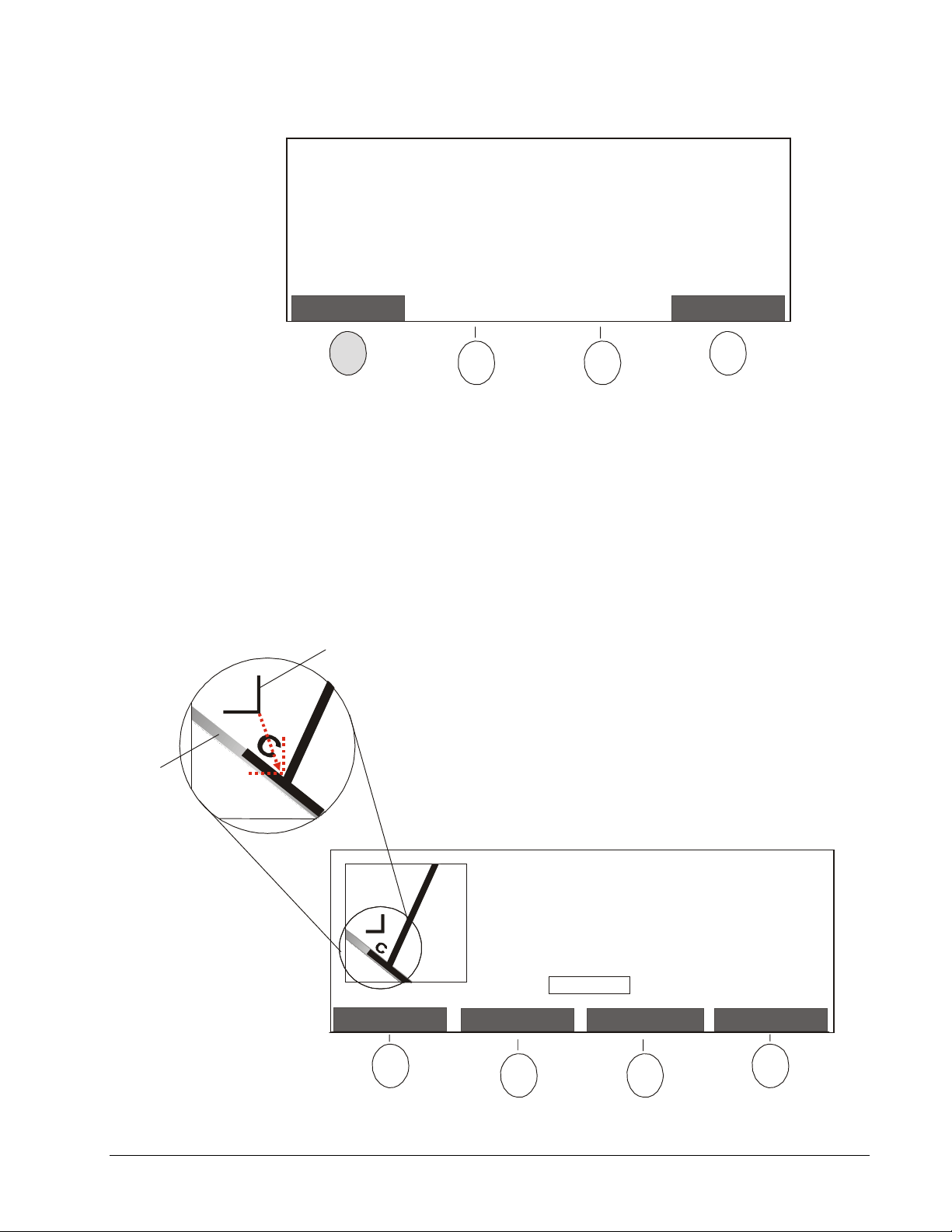
borders. Adjust the position of each image border as follows:
Using the captured image displayed on the screen, press the Left/Right or
a
Down/Up button and use the Scroll buttons to align the marker inside the corner
indicated by a capitalized letter. To move the marker up, press the right arrow
button. To move the marker down, press the left arrow button. You can’t change
the angle of the marker.
Whiteboard
Frame
As shown in the following figure, the whiteboard frame may be captured at an
angle. Align the corner point of the marker inside the indicated corner in the
captured image. Don’t be concerned if you can’t align the sides of the marker.
Marker
Align the marker inside the corner labeled
with a C.
* Press Left/Right and use Scroll buttons to
make horizontal adjustments.
* Press Down/Up and use Scroll buttons to
make vertical adjustments.
* Press Continue when done.
Mode: Left/Right
ReturnDown/UpLeft/RightContinue
42
Refining Image Alignment and Adding an Image Frame
Page 49

When the marker is where you want, press the Continue button.
b
Repeat the above steps until you reach the screen that displays the corner labeled
c
with an “H”.
Adjust the marker for the corner labeled with an “H”. When the marker is where you
d
want, press the Save button.
A message will appear once your border adjustments have been saved.
Press the Return button.
9
If more than one Camera Boom is connected to your Control Unit, repeat this procedure for
10
each Camera Boom, beginning on page 39.
Adding/Removing the Image Frame at the Control Unit
Depending on how you plan to use captured images, you may want to add or remove the
image frame. For example, if you have one whiteboard and plan to manipulate the image in
other programs, you’ll probably want to add a frame to demarcate the graphic. On the other
hand, if you plan to combine captured images from multiple whiteboards, you’ll likely want
to remove the image frame.
Press the Options button on the Control Unit.
1
No session is active.
Press Open Session to begin.
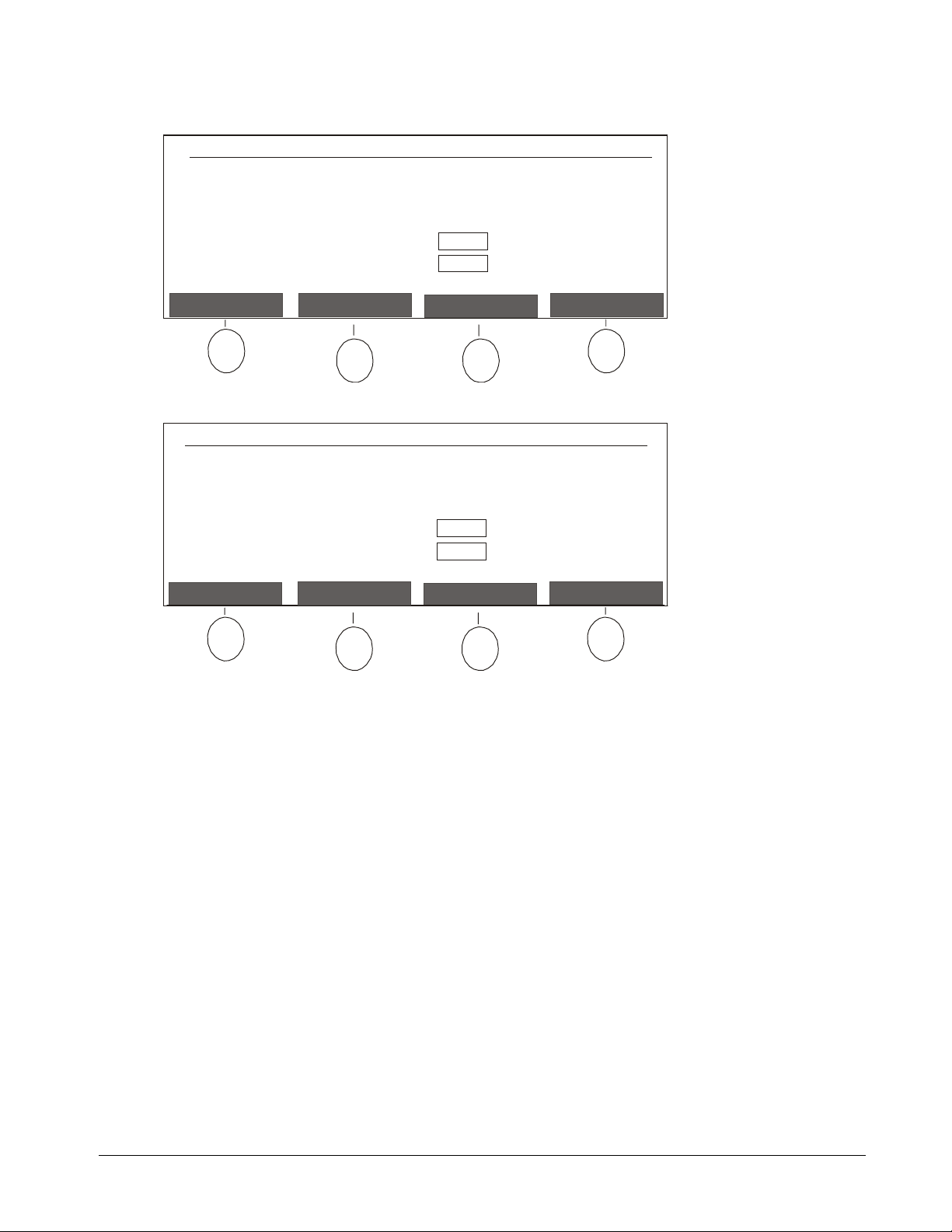
The Options Mode screen will appear.
Options Mode
* Use Scroll buttons to select an Option.
* Press Continue when done.
Option: Add/Remove Frame in Captured Images
Hawkeye 480C 1.0.17
Continue
IP Address is:
192.168.1.10
or hawksetup
Options
Return
Use the Scroll button to select the
2
and press the Continue button.
Refining Image Alignment and Adding an Image Frame
Add/Remove Frame in Captured Images
option
43
Page 50

The following screen will appear.
* Use Scroll buttons to add or remove image
frame.
* Press Save when done.
Image Frame: add
IP Address is:
192.168.1.10
or hawksetup
Image-Saving
Software: active
CancelSave
Use the Scroll buttons to select
3
add
or
remove
and press the Save button.
Adding/Removing the Image Frame Using a Web Browser
Open a Web browser, such as Microsoft Internet Explorer or Netscape Communicator,
1
on a computer connected to the same network as the Control Unit.
Enter the
2
Address
IP Address
box in the Web browser.
For example, if the IP Address of your Control Unit is “102.123.1.11”, you’d enter
“http://102.123.1.11/config”.
The Enter Network Password dialog box will appear.
Enter “admin” as the
3
Configuration page, leave the
was assigned. Then click OK.
The Configuration page will appear.
Click
4
Add/Remove Frame in Captured Images
The Add/Remove Frame in Captured Images page will appear.
Click the down arrow beside
5
Click the Submit Configuration button.
6
or
Host Name
User Name
Password
Option
assigned to your Control Unit and “/config” in the
. If this is the first time you’ve accessed the
blank. Otherwise, enter the
Password
in the Configuration page.
and select
add
or
remove
.
that
44
The Configuring Frame in Captured Images page will appear.
7
Click
Back to Configuration page
.
Refining Image Alignment and Adding an Image Frame
Page 51

Updating Control Unit Firmware
SMART Technologies will periodically issue firmware updates for the Hawkeye Control Unit.
The procedure for updating Control Unit firmware varies, depending on whether the Control
Unit is connected to a network:
•
If your Control Unit is connected to a network, you can simply update the firmware
using a Web browser at your desk (page 46).
•
If your Control Unit isn’t connected to a network, you’ll have to configure a computer to
network with the Control Unit before you can begin updating firmware (page 45).
: Currently, you can only update Control Unit firmware on a Windows computer. This
NOTE
feature is not available for Macintosh computers.
To configure a computer to network with the Control Unit:
Use a crossover cable, or a straight-through network cable and a hub, to connect a
1
computer to the Control Unit.
: Keep this computer and the Control Unit isolated from the main network until
NOTE
you’ve finished configuring the Control Unit.
Disconnect the power cable from the Control Unit, wait a minute and then reconnect the
2
power cable.
Using the computer, click the Start button on the Windows taskbar.
3
Select
4
5
6
7
8
Control Panel
The Control Panel dialog box will appear.
Double-click the Network icon in the Control Panel dialog box.
The Network dialog box will appear.
If the Configuration tab isn’t already displayed in the Network dialog box, click the
Configuration tab.
Select the
tab.
Click the Properties button.
The TCP/IP Properties dialog box will appear.
TCP/IP
from the
protocol from the list of installed components in the Configuration
Settings
menu.
Click the IP Address tab in the TCP/IP Properties dialog box.
9
Select the
10
Enter the following number in the
11
“192.168.1.xx”, where xx is any number other than 10.
(“192.168.1.10” is the IP Address assigned to every Control Unit during manufacturing.)
Specify an IP address
radio button.
IP Address
Updating Control Unit Firmware
box:
45
Page 52

Enter “255.255.255.0” in the
12
Click OK.
13
Subnet Mask
box.
You’ll be returned to the Configuration tab of the Network dialog box.
Click OK again.
14
Restart the computer.
15
To update Control Unit firmware:
Write down the
1
IP Address
Unit screen.
Press Open Session to begin.
Open a Web browser on a computer that is networked to the Control Unit.
2
or
Host Name
No session is active.
that appears on the right side of the Control
IP Address is:
192.168.1.10
or hawksetup
3
Enter the
Address
IP Address
box in the Web browser.
or
Host Name
assigned to your Control Unit and “/config” in the
For example, if the IP Address of your Control Unit is “102.123.1.11”, you’d enter
“http://102.123.1.11/config”.
The Enter Network Password dialog box will appear.
Enter “admin” as the
4
Configuration page, leave the
User Name
. If this is the first time you’ve accessed the
Password
blank. Otherwise, enter the
Password
was assigned.
Click OK.
5
The Configuration page will appear.
6
Click
Update Firmware
in the Configuration page.
A Web page will appear, reminding you to save captured images. When you update the
firmware, your Control Unit will be automatically restarted and any images stored on the
Control Unit will be deleted.
Click the Erase Images and Continue button.
7
The Update Firmware page will appear.
Enter the file path and name of the update file, or click the Browse button to look for the
8
file you want.
Click the Upload button.
9
that
46
The Updating Firmware page will appear.
Power to the Control Unit will automatically turn off and then on again. Once the Control
Unit is back on, the firmware update will take effect.
If you up a computer to network with the Control Unit in order to update firmware,
10
disconnect the computer from the Control Unit and return the network configuration on
the computer to the original settings.
Updating Control Unit Firmware
Page 53

Using Hawkeye at a Whiteboard
Using Hawkeye at a whiteboard is simple. Just follow the instructions displayed on the
Control Unit screen and press the Control Unit buttons to capture, print and delete images
of your whiteboard notes. Some buttons on the Control Unit are reserved for specific
functions; others are assigned as needed. Buttons that can be assigned are called soft
buttons. The current function of each soft button is identified on the Control Unit screen.
Session 1
Image 1 of 4
Fri Aug 18 2000
14:30:09
Board 1
Control Unit
Screen
Print Delete
IP Address is:
102.123.1.11
or Boardroom
Image-Saving
Software: active
Options
Functions of Soft
Buttons Vary
Scroll
Close SessionOpen Session
Soft Buttons
Power Indicator
Light
Capture
Scroll Buttons
Open Session Button
Close Session Button
Capture Button
Control Unit Interface
For best results when writing on the whiteboard:
•
Use regular dry-erase markers and not fine-point markers.
•
Avoid light colors such as pink or yellow. Use dark colors instead.
•
Do not use excessively small print. Each letter should be at least 1½" (3.81 cm) in
height.
Reactivating the Control Unit
After an extended period of inactivity, Hawkeye will go into sleep mode. The screen will
appear blank and the power indicator light will flash slowly. To reactivate the Control Unit,
press any button.
Starting or Resuming a Session
Hawkeye organizes images into sessions. If the Control Unit became inactive while a
session was open, when it’s reactivated a screen will appear indicating that a session is still
open. At that point, you can either resume the current session or start a new one. If the
Control Unit became inactive after a session was ended, when it’s reactivated you’ll be
prompted to open a new session. You can also initiate a new session yourself at any time.
Using Hawkeye at a Whiteboard
47
Page 54

As soon as you start a new session, the images captured during the previous session are
no longer available on the Control Unit. However, if the Image-Saving Software was active
during the session, images from that session will be available on the computer that has the
software installed. The current status of the Image-Saving Software is displayed on the
right side of the Control Unit.
New session started.
Session 1
Ready to capture.
When you are ready to record an image of
the board, press Capture
.
Fri Aug 18 2000
13:48:04
Board 1
IP Address is:
102.123.1.11
or Boardroom
Image-Saving
Software: active
Options
Current Status of
Image-Saving Software
If your Control Unit isn’t connected to a network, you’ll need to print the images from the
previous session before you start a new one.
To start a new session:
Press the Open Session button on the Control Unit.
Once a new session has been initiated, the following screen will appear, enabling you to
capture the notes on your whiteboard whenever you’re ready.
New session started.
Ready to capture.
When you are ready to record an image of
the board, press Capture
.
Session 1
Fri Aug 18 2000
13:48:04
Board 1
IP Address is:
102.123.1.11
or Boardroom
Image-Saving
Software: active
Options
48
To resume a session after reactivating the Control Unit:
Press the Resume Session button on the Control Unit.
A session with 4 images is currently open:
* Press Resume Session to continue this session.
* Press Open Session to immediately end this
session and start a new one.
After a session ends, images can be viewed by
browsing to http://Boardroom on any computer
connected to the same network as the Control Unit
or by using the files created by the Image-Saving
Software.
A screen will appear, indicating that the session has been resumed and the Control Unit is
ready to capture a new image.
Using Hawkeye at a Whiteboard
Session 1
Image 4 of 4
Fri Aug 18 2000
14:30:09
Board 1
IP Address is:
102.123.1.11
or Boardroom
Image-Saving
Software: active
OptionsResume Session
Page 55

Capturing the Notes from Your Whiteboard
Press the Capture button on the Control Unit. Remember to stand away from the
1
whiteboard clear of the cameras while the image is being captured.
If more than one Camera Boom is connected to your Control Unit, a screen showing
2
thumbnails of captured images from each whiteboard will appear. Press the button for
the Board you want.
Please select the Board you want.
Board 3Board 2Board 1
: The images displayed in this screen are only provided to help you select a
NOTE
whiteboard. They have not undergone the image improvement processing normally
provided by Hawkeye.
A message will appear, indicating that the image is being captured and perfected.
Another message will appear when the Control Unit is ready to capture a new image.
Adjusting Control Unit Screen Brightness
If you’re having problems reading the information on the Control Unit screen, try adjusting
the screen brightness.
Press the Options button on the Control Unit.
1
Session 1
Image 4 of 4
Fri Aug 18 2000
14:30:09
Board 1
IP Address is:
102.123.1.11
or Boardroom
Ready to capture a new image.
Image-Saving
Software: active
OptionsDeletePrint
Using Hawkeye at a Whiteboard
49
Page 56

The Options Mode screen will appear.
Options Mode
* Use Scroll buttons to select an Option.
* Press Continue when done.
Option: Adjust Screen Brightness
Hawkeye 480C 1.0.17
Continue
Use the Scroll buttons to select the
2
Adjust Screen Brightness
Return
option and press the
Continue button.
The following screen will appear.
Session 1
* Use Scroll buttons to adjust screen brightness.
Press Save when done.*
0 102030 4050 6070
Use the Scroll buttons to adjust the brightness of the display. To decrease the
3
80
100
90
Image 4 of 4
Fri Aug 18 2000
14:32:13
Board 1
IP Address is:
102.123.1.11
or Boardroom
Image-Saving
Software: active
CancelSave
brightness, press the left arrow button. To increase the brightness, press the right arrow
button. Then press the Save button.
50
The Options Mode screen will reappear.
Press the Return button.
4
Using Hawkeye at a Whiteboard
Page 57

Printing Captured Images at the Control Unit
If you configured a local or network printer to work with the Control Unit, you can print an
individual image or all of the images in the current session while you are at the whiteboard.
Press the Print button on the Control Unit.
1
Session 1
Image 4 of 4
Fri Aug 18 2000
14:30:09
Board 1
IP Address is:
102.123.1.11
or Boardroom
Ready to capture a new image.
The following screen will appear.
Print Mode
Image-Saving
Software: active
OptionsDeletePrint
Session 1
Image 4 of 4
Fri Aug 18 2000
14:34:12
Board 1
IP Address is:
102.123.1.11
or Boardroom
Image-Saving
Software: active
OptionsPrint AllPrint Current Return
To print an individual image, use the Scroll buttons to navigate to the image you want
2
and press the Print Current button.
Or
To print all of the images in the current session, press the Print All button.
Using Hawkeye at a Whiteboard
51
Page 58
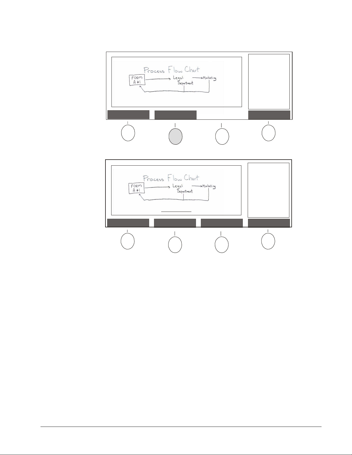
Deleting Captured Images at the Control Unit
Press the Delete button on the Control Unit.
1
Session 1
Image 4 of 4
Fri Aug 18 2000
14:30:09
Board 1
IP Address is:
102.123.1.11
or Boardroom
Ready to capture a new image.
The following screen will appear.
Delete Mode
Image-Saving
Software: active
OptionsDeletePrint
Session 1
Image 4 of 4
Fri Aug 18 2000
14:34:12
Board 1
IP Address is:
102.123.1.11
or Boardroom
Image-Saving
Software: active
OptionsDelete AllDelete Current Return
To delete an individual image, use the Scroll buttons to navigate to the image you want
2
and press the Delete Current button.
Or
To delete all of the images in the current session, press the Delete All button.
Ending a Session
Don’t leave the room before you’re certain you’ve captured all of the notes on your
whiteboard. If your Control Unit isn’t connected to a network, make sure you print all of the
captured images before you leave or close the session.
When a new session is started, the previous one is ended automatically. You can also
choose to end a session as a separate task. After a session has been ended, the images in
that session can no longer be viewed on the Control Unit. However, if the Control Unit has a
network connection and the Image-Saving Software was active during the previous
session, you can access the images from that session on the computer that has the
software installed. For information about using Image-Saving Software files, refer to pages
54–56.
52
Using Hawkeye at a Whiteboard
Page 59
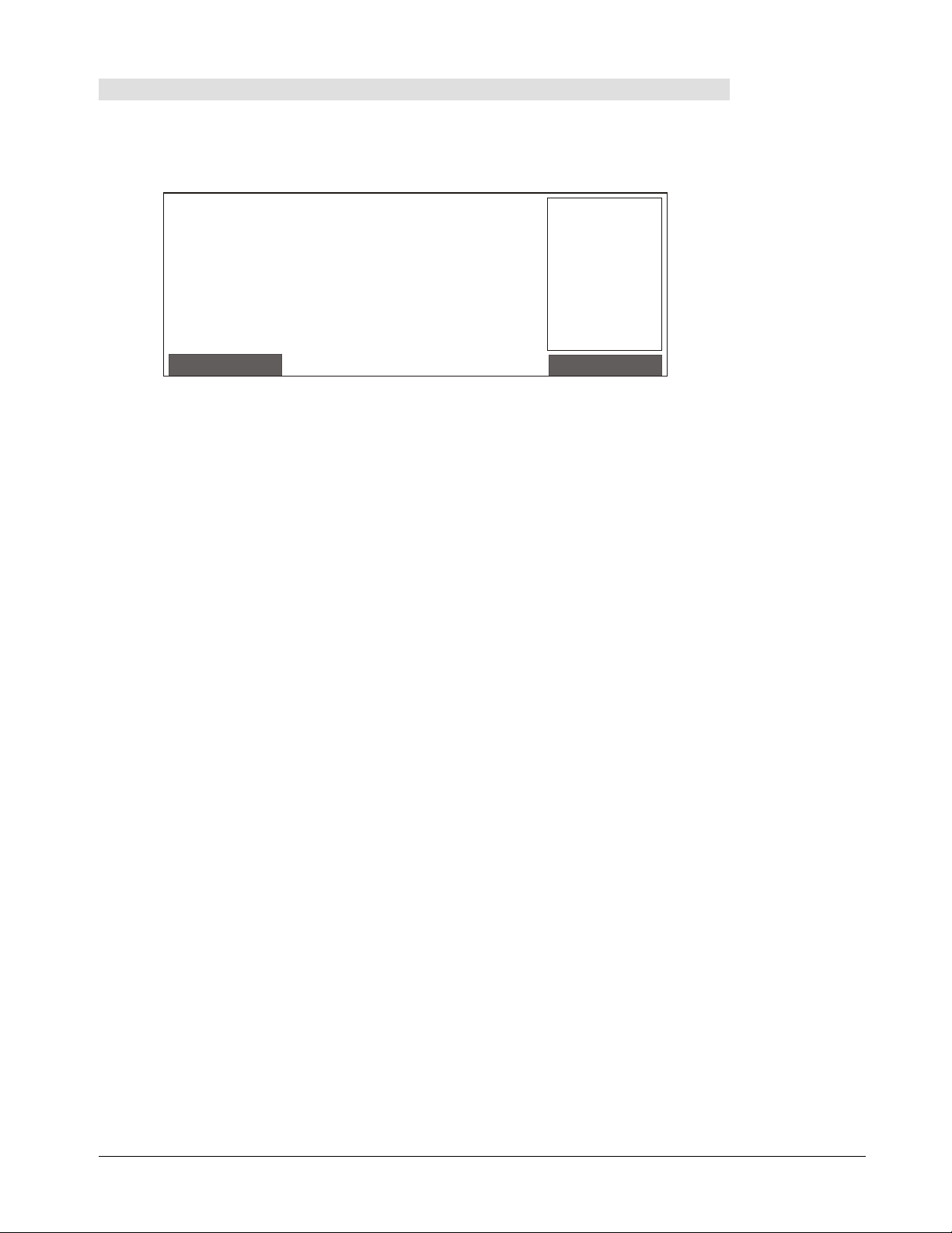
To end a session:
When you’ve finished capturing, printing and deleting images in the current session,
1
press the Close Session button on the Control Unit.
The following screen will appear, asking you to confirm that you want to end the
session.
A session with 4 images is currently open:
* Press Resume Session to continue this session.
* Press Open Session to immediately end this
session and start a new one.
After a session ends, images can be viewed by
browsing to http://Boardroom on any computer
connected to the same network as the Control Unit
or by using the files created by the Image-Saving
Software.
Press the Close Session button again to complete your request.
2
Session 1
Image 4 of 4
Fri Aug 18 2000
14:30:09
Board 1
IP Address is:
102.123.1.11
or Boardroom
Image-Saving
Software: active
OptionsResume Session
Using Hawkeye at a Whiteboard
53
Page 60

Working with Captured Images at Your Desk
If the Control Unit is connected to a local area network, captured images can be accessed
on a Windows-based computer in two ways: by using Image-Saving Software files or by
accessing a Sessions page for the Control Unit.
The files created by the Image-Saving Software provide access to both the captured
images currently stored on the Control Unit and images no longer available from the
Control Unit itself. As long as the Image-Saving Software is active, images captured at the
Control Unit will be saved to the computer on which the software has been installed. The
Image-Saving Software creates an index of all the captured images within a session as an
HTML page that can be opened with any Web browser to view, copy and print the captured
images. Each captured image is also available as a separate JPEG file.
The Sessions page only provides access to the images currently stored on the Control Unit.
The maximum number of images that can be stored on a Control Unit is approximately 20.
When this storage capacity is exceeded, the captured images will no longer be available on
the Sessions page. A Web browser can be used on any computer within the same network
as the Control Unit to access the Sessions page.
Using the Image-Saving Software Files
Captured images will only be saved on the computer if the Image-Saving Software is active.
Before using the Control Unit to capture notes at the whiteboard, check that the ImageSaving Software is active.
New session started.
Ready to capture.
When you are ready to record an image of
the board, press Capture
.
Current Status of
Image-Saving Software
Session 1
Fri Aug 18 2000
13:48:04
Board 1
IP Address is:
102.123.1.11
or Boardroom
Image-Saving
Software: active
Options
The Image-Saving Software creates two types of files: an HTML index and separate JPEG
files for each captured image. The index and image files for each session are stored within
one folder, which may be in a location accessible by other users. If you’re not sure where
the Image-Saving Software files are stored, check with your systems administrator.
To activate the Image-Saving Software:
While the Image-Saving Software is active, the Hawkeye icon will appear in the System
Tray on your Windows Taskbar.
54
Hawkeye Icon in System Tray
Working with Captured Images at Your Desk
Page 61

If the Hawkeye icon isn’t displayed in your System Tray, you can open the program by
pressing the Start button, pointing to
Software
.
Programs
and selecting
Hawkeye Image-Saving
To manually update the index of captured images:
The Image-Saving Software maintains an index of all the captured images within a session.
Normally, you won’t need to manually update this index because it’s updated automatically
whenever the software is started or a new image is captured. However, if you modify image
files using Windows Explorer, your changes may not be included in the HTML page used
as an index and you may need to manually update the index.
Double-click on the Hawkeye icon in the System Tray.
1
Hawkeye Icon in System Tray
The Hawkeye Image-Saving Software Properties dialog box will appear.
Click the Update Image Indexing button.
2
Click OK in the message box that appears.
3
To access captured images:
Use Windows Explorer to navigate to the directory in which the captured images you
1
want have been stored.
On the computer with the Image-Saving Software, you can double-click on the
Hawkeye icon in the System Tray and then click on the link included in the Hawkeye
Image-Saving Software Properties dialog box to open the file directory with the
captured images.
There will be several files listed under the directory for each session.
Double-click on the
2
index.html
file.
An index for the session will appear as an HTML page in your Web browser.
Working with Captured Images at Your Desk
55
Page 62
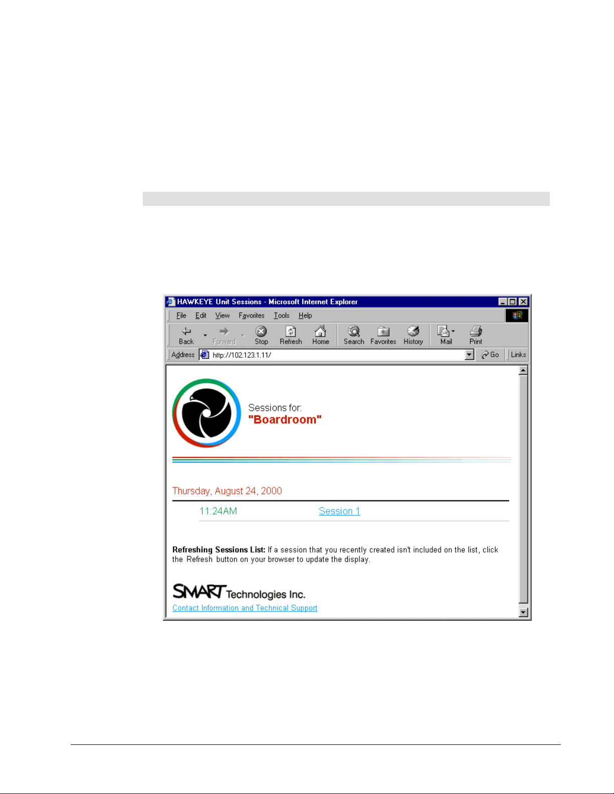
To print a captured image, double-click on the thumbnail and then click the Print button
3
on the toolbar or select
: Use Windows Explorer to copy, delete or rename files.
NOTE
Print
from the
File
menu.
Using the Sessions Page
If the Control Unit is connected to a local area network, everyone connected to that network
who has access to a Web browser can view, copy, print and save captured images using
the Sessions page. However, only images that are currently stored on the Control Unit are
available on the Sessions page.
To access captured images using the Sessions page:
Write down the
1
Unit screen.
IP Address
or
Host Name
that appears on the right side of the Control
Open a Web browser to the
2
example, if the IP Address of the Control Unit is “102.123.1.11”, you’d type
“http://102.123.1.11” in the
A Sessions page for the Hawkeye Control Unit will appear.
IP Address
Address
box.
or
Host Name
of the Control Unit. For
56
Working with Captured Images at Your Desk
Page 63

If a password was assigned to the Sessions page, enter “guest” as the
3
the
Password
To print a captured image, double-click on the thumbnail and then click the Print button
4
on the toolbar or select
To save a captured image in Internet Explorer, right-click on the image and select
5
Picture As
that was assigned, and then click OK.
Print
from the
File
menu.
from the pop-up menu. Specify a file path, file type and name in the Save
User Name
Picture dialog box. You can save captured images in the JPEG file interchange (.jpg) or
Windows bitmap (.bmp) format.
Or
To save a captured image in Netscape Communicator or Netscape Navigator, rightclick the thumbnail you want and select
Save Image As
from the pop-up menu. Specify
the file path, file type and name in the Save Image dialog box. You can save captured
images in the JPEG file (.jpg) or Windows bitmap (.bmp) format.
To copy a captured image in Internet Explorer, right-click on the thumbnail you want
6
and select
from the pop-up menu that appears. The image can now be pasted
Copy
into any open Windows application in the JPEG file interchange format (.jpg).
and
Save
Working with Captured Images at Your Desk
57
Page 64

Customer Support
While SMART’s Technical Support team welcomes your call, if you experience problems
with any SMART product you may want to contact your local dealer first. SMART’s dealers
can readily provide you with quick advice regarding your SMART product.
Contacting SMART Technical Support
You may contact SMART Technical Support at:
Telephone
Fax (24 hours)
E-mail:
Web site
Please provide us with the product purchase date, the dealer’s name, and the serial
numbers of your Control Unit and Camera Boom(s). The Control Unit has two serial
number labels: one underneath the Control Unit near the connection ports and another at
the back of the Control Unit. Each Camera Boom also has two serial number labels: one
inside the door at the front and another at the back of the Camera Boom base.
: toll-free at 1.866.518.6791 or outside North America at +1.403.228.5940
(Available 7 a.m. − 6 p.m. Mountain time from Monday to Friday)
: 403.245.0366
support@smarttech.com
: www.smarttech.com
Other SMART Contacts
Sales and Marketing
Fax (24 hours)
E-mail:
Address
info@smarttech.com
: SMART Technologies Inc.
Suite 600, 1177 − 11th Avenue SW
Calgary, AB CANADA T2R 1K9
: toll-free at 1.888.42.SMART or outside North America at
+1.403.245.0333
: 403.228.2500
Product Warranty
Hawkeye 480C is covered by a one-year parts and labor warranty. If you need to return
defective merchandise, call SMART Technical Support to receive the appropriate Return of
Merchandise Authorization, as well as shipping instructions, so that your unit can be sent to
an authorized service center.
58
Warranty Shipping Charges
Shipping charges incurred from warranty service are paid as follows: The customer is
responsible for shipping the system to the service center. SMART pays return shipping via
ground service on any product returned for service within the warranty period. Any charges
associated with a customer-requested rush order are billed to the customer. Following the
warranty period, the customer is responsible for shipping the product to and from the
service center.
Read the warranty shipped with your Hawkeye 480C for details.
Registration
A User Registration Card has been shipped with your Hawkeye 480C. To facilitate user
support and to receive news and updates, fill in and mail the card to SMART Technologies.
Customer Support
Page 65

You can also register online at www.smarttech.com, either when you initially install the
Hawkeye system or later. By registering, you provide us with the information we need to
serve you better. If you’ve indicated that you would like to receive information on product
upgrades, we’ll e-mail you so that you always have the most recent information on the
newest firmware and tools developed for use with Hawkeye 480C.
Customer Support
59
Page 66

Index
A
Accessing
Admin Functions at the Control Unit, 23–24
Admin Functions on a Web Browser, 29
Captured Images, 54–57
Image-Saving Software Files, 55–56
Sessions Web Page, 56–57
Activating Image-Saving Software, 54
Adjusting Screen Brightness on Control Unit,
49–50
Administration Password
Changing at Control Unit, 24–25
Changing with Web Browser, 30
Aligning Captured Images, 39–43
Assigning Board Numbers to Camera Booms,
37–38
C
Calibrating Camera Boom
Image Alignment, 39–43
Camera Boom
Adding a Frame in Captured Images, 43–
44
Connecting Multiple Camera Booms, 7–8
Connecting to Control Unit, 11–13
Installing Multiple Camera Booms, 4
Mounting on the Wall, 5–7
Numbering Multiple Camera Booms, 37–38
Refining Image Alignment, 39–43
Removing the Frame in Captured Images,
43–44
Security, 7
Captured Images
Adding a Frame, 43–44
Alignment, 39–43
Capturing Whiteboard Notes, 49
Copying, 54–57
Deleting, 52
Image-Saving Software, 35–36, 54–56
Printing from a Computer, 54–57
Printing from a Control Unit, 51
Removing the Frame, 43–44
Saving, 35–36, 54–57
Viewing, 54–57
Capturing Whiteboard Notes, 49
Change Admin Password Web Page, 30
Computer IP Address for Image-Saving
Software, 35–36
Configuration Web Page, 29
Configure Network Printer Web Page, 34
Configure Network Web Page, 30–31
Configure Sessions Page Password Web
Page, 30
Configuring
Computer to Network with Control Unit,
45–46
Control Unit Date and Time, 28, 31
Image-Saving Software, 35–36
Local Printer, 17–18
Network Printer, 31–34
Network Settings at Control Unit, 23–28
Network Settings with Web Browser, 30–
31
Connecting
Camera Boom to Control Unit, 11–13
Control Unit to Network, 20–31
Control Unit to Power, 15–16, 21–22
Local Printer to Control Unit, 14
Multiple Camera Booms, 7–8
Control Unit
Accessing Admin Functions, 23–24
Adjusting Screen Brightness, 49–50
Administration Password, 24–25
Capturing Whiteboard Notes, 49
Changing Date and Time, 28, 31
Connecting Local Printer, 14
Connecting to Camera Boom, 11–13
Deleting Captured Images, 52
Ending a Session, 52–53
Mounting on the Wall, 9–11
Networked, 19–34
Power Source for Networked, 21–22
Power Source for Stand-Alone, 15–16
Printing Captured Images, 51
Reactivating, 47
Resuming a Session, 47–48
Security, 11
Selecting a Local Printer, 17–18
Selecting a Network Printer, 31–34
Starting a Session, 47–48
Temperature, 31
Updating Firmware, 45–46
Copying Captured Images, 54–57
D
Date and Time of Control Unit
Configuring at Control Unit, 28
Configuring with Web Browser, 31
DHCP Network
Changing Control Unit Date and Time, 28,
31
Configuring at Control Unit, 25–28
Configuring with Web Browser, 30–31
Connecting Control Unit to Power, 21–22
Connecting Network Cable, 20
Selecting a Network Printer, 31–34
Tasks Required, 19
Updating Control Unit Firmware, 45–46
60
Index
Page 67

E
P
Ending a Session, 52–53
F
Firmware on Control Unit, 45–46
Frame in Captured Images, 43–44
H
Hawkeye Image-Saving Software
Configuring, 35–36
Using Captured Images, 54–56
I
IEEE 1394 Cable, 7–8, 11–13
Image-Saving Software
Configuring, 35–36
Using Captured Images, 54–56
Internet Explorer
Configuring Network Settings for Control
Unit, 29–31
Selecting Network Printer for Control Unit,
34
Using Captured Images, 54–57
M
Mounting
Camera Boom, 5–7
Control Unit, 9–11
N
Netscape Communicator
Configuring Network Settings for Control
Unit, 29–31
Selecting Network Printer for Control Unit,
34
Using Captured Images, 54–57
Netscape Navigator
Configuring Network Settings for Control
Unit, 29–31
Selecting Network Printer for Control Unit,
34
Using Captured Images, 54–57
Network
Accessing Captured Images, 54–57
Changing Control Unit Date and Time, 28,
31
Configuring at Control Unit, 25–28
Configuring with Web Browser, 30–31
Connecting Computer for Upgrading
Control Unit Firmware, 45–46
Connecting Network Cable, 20
Connecting Power Cable, 21–22
Selecting a Network Printer, 31–34
Networked Control Unit, 19–34
Numbering Multiple Camera Booms, 37–38
Password
Administration Password, 24–25, 30
Sessions Page, 30
Power Cables
Networked Control Unit, 21–22
Stand-Alone Control Unit, 15–16
Printer
Networked Control Unit, 31–34
Standalone Control Unit, 14, 17–18
Printing Captured Images
At a Control Unit, 51
From a Computer, 54–57
R
Raceway for Cable, 8
Reactivating Control Unit, 47
Refining Image Alignment, 39–43
Registration of Product, 58
Resuming a Session, 47–48
S
Saving Captured Images, 35–36, 54–57
Screen Brightness on Control Unit, 49–50
Session
Assigning Password to Web Page, 30
Ending, 52–53
Resuming, 47–48
Starting, 47–48
Sessions Web Page, 56–57
Sleep Mode, 47
SMART Web Site, 59
Soft Buttons, 47
Standalone Control Unit, 14–18
Starting a Session, 47–48
Static IP Network
Changing Control Unit Date and Time, 28,
31
Configuring at Control Unit, 25–28
Connecting Control Unit to Power, 21–22
Connecting Network Cable, 20
Selecting a Network Printer, 31–34
Tasks Required, 19
Updating Control Unit Firmware, 45–46
Stitching Captured Image, 37
T
Temperature of Control Unit, 31
Time and Date on Control Unit, 28
Time/Date Web Page, 31
U
Unpacking Components, 4
Update Firmware Web Page, 45–46
Index
61
Page 68

W
Warranty, 58
Web Browser
Configuring Network Settings for Control
Unit, 29–31
Selecting Network Printer for Control Unit,
34
Using Captured Images, 54–57
Whiteboard
Connecting Multiple Camera Booms, 7–8
Installing Multiple Camera Booms, 4
Mounting Camera Booms, 5–7
Numbering Multiple Camera Booms, 37–38
Writing Tips, 47
62
Index
Page 69

Technologies Inc.
Suite 600, 1177 - 11th Avenue SW, Calgary, AB CANADA T2R 1K9
Support: 1.866.518.6791 or outside North America +1.403.228.5940
Main Switchboard: 1.888.42.SMART or outside North America +1.403.245.0333
Fax (24 hours): 403.245.0366
support@smarttech.com www.smarttech.com
Printed in Canada
99-229-01 REV AO
 Loading...