

Page 1
Installation and
Integrator’s Guide
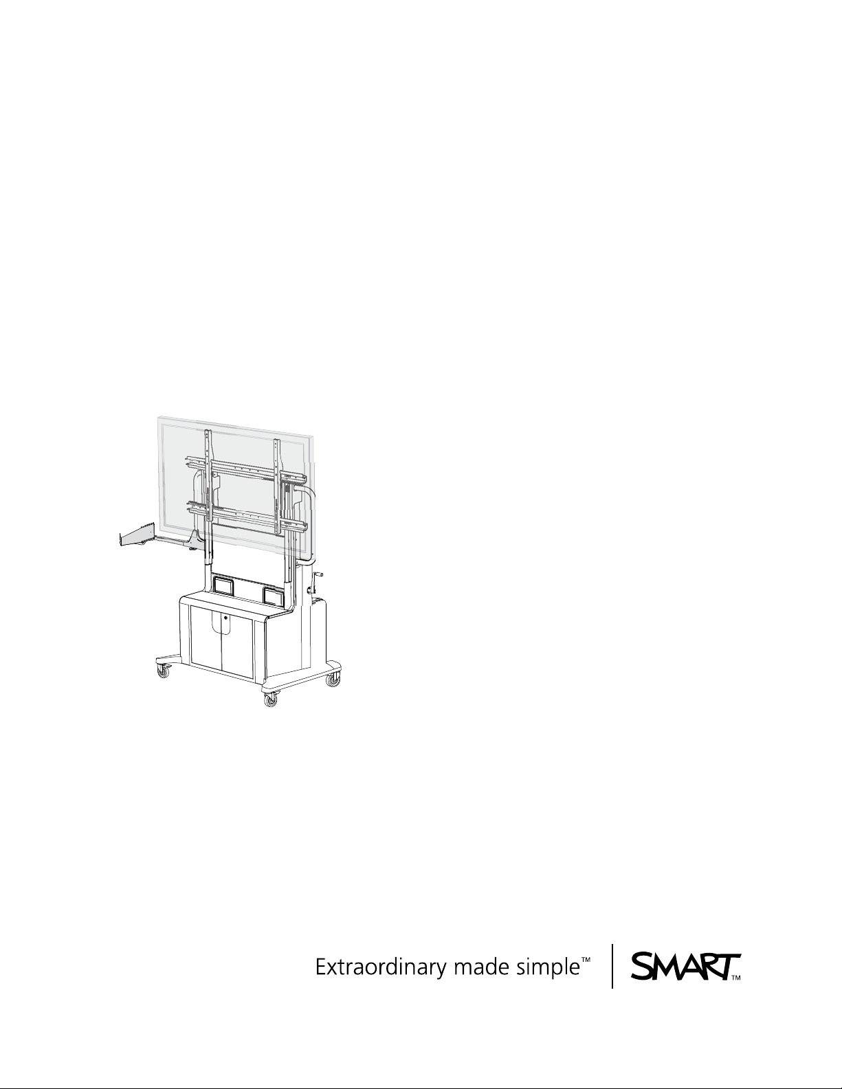
SMART Mobile Stand
for Interactive Displays
Models FSSBID 100
and FSSBID 100H
Page 2

Product Registration
If you register your SMART product, we’ll notify you of new features and software
upgrades.
Register online at www.smarttech.com/registration
.
Keep the following information available in case you need to contact SMART
Technical Support.
Serial Number: ___________________________________________________
Date of Purchase: ___________________________________________________
Trademark Notice
SMART Board, smarttech, Senteo and the SMART log o are trademarks or registered trademarks of SMART Technologies
ULC in the U.S. and/or other countries. Phillips is a registered trademark of Phillips Screw Company. TORX is a registered
trademark of Acument Intellectual Properties, LLC in the United States or other countries. All other third-party product and
company names may be trademarks of their respective owners.
Copyright Notice
©2009 SMART Technologies ULC. All rights reserved. No part of this publication may be reproduced, transmitted,
transcribed, stored in a retrieval system or translated into any language in any form by any means without the prior written
consent of SMART Technologies ULC. Information in this manual is subject to change without notice and does not
represent a commitment on the part of SMART.
Patent No. US5448263; US6141000; US6320597; US6326954; US6337681; US6741267; US6747636; US6803906;
US6919880; US6947032; US6954197; US6972401; US7151533; US7184030; US7236162; US7289113; US7411575;
CA2058219; CA2252302; CA2386094; CA2453873; EP1297488; ES2279823; ZL0181236.0; and DE60124549.
Other patents pending.
07/2009
Page 3

Important Information
Before you install and use your SMART M obile Stand, read and understand the safety
warnings and precautions in this user’s guide and the included warnings document.
These safety warnings and precautions describe the safe and correct operation of
your SMART Mobile Stand and its accessories, helping you prevent injuries and
equipment damage.
Safety Warnings and Cautions
WARNING
• Failure to follow the installation instructions included with your
SMART Mobile S t and for interactive displays could result in personal injury or
product damage.
• Make sure that you properly engage and secure the vertical brackets both to
your flat-panel display and to your SMART Mobile Stand.
• Read the safety warnings, precautions and other important information
contained in the documentation included with your other SMART products
and published by your flat-panel display’s ma nufacturer.
• Two people are required to safely assemble your SMART Mobile Stand
and to mount or remove your flat-panel display and your SMART Board™
interactive display frame or SMART Board for Flat-Panel Displays
interactive overlay.
• Lock the casters before installing or working with your flat-panel display
on your SMART Mobile Stand, or adjusting its height.
• To prevent injury, be aware of crush and pinch locations
on the product (marked with the crush symbol) during assembly
and use.
• Do not rest your hand on the stand’ s universal mount or under the interactive
product’s pen tray or pencil ledge while adjusting the height of your
SMART Mobile Stand.
99-00962-20 REV C0
Page 4

ii | IMPORTANT INFORMATION
• Use the SMART Mobile Stand’s three grab bars to move the unit.
Do not press, pull or push on the flat-panel display, interactive overlay or
display frame, cabinet, doors, rear access panel plastics or vertical brackets.
• Before moving your SMART Mobile Stand, make sure that you unlock the
casters. These casters are designed to roll on common indoor surfaces. While
you move the unit, your view may be partially obstructed. Be aware of
surrounding obstacles.
• Do not move your SMART Mobile Stand while external cables are connected
or when the power is on.
• You must connect the USB cable that came with your SMART Mobile Stand
to a computer that has a USB 2.0 compliant interface and that bears the USB
logo. In addition, the USB source computer must be compliant with
CSA/UL/EN 60950 and bear the CE mark and CSA and/or UL Mark(s)
for CAS/UL 60950. This is for operating safety.
• Ensure that any cables extending across the floor to your SMART Mobile
Stand are properly bundled and marked to prevent a tripping hazard.
• Do not stand (or allow children to stand) on a chair to touch the surface
of your flat-panel display. Instead, rotate your SMART Mobile Stand’s
height-adjustment handle to lower your display to the appropriate height.
• Do not climb or ride (or allow children to climb or ride) on your SMART Mobile
Stand. Climbing or riding on your SMART Mobile Stand could result
in personal injury or product damage.
• (For European customers only)
Your SMART Mobile Stand should be used only with European TN and TT
power distribution systems.
It is not suitable for older, IT-type power distribution systems found in some
European countries. “This system (IT - type) is widely used isolated from ear th,
in some installations in France, with impedance to earth, at 230/400V, and in
Norway, with voltage limiter, neutral not distributed, at 230V line- to-line.”
(IEC 60950:1999)
Contact qualified personnel if you are uncertain about the type of power
system available where you are installing your SMART Mobile Stand.
• To reduce the risk of fire or electric shock, do not expose your SMART Mobile
Stand to rain or moisture.
99-00962-20 REV C0
• Your SMART Mobile Stand is designed to operate with a maximum power
consumption of 1200 W. Exceeding this consumption could result in fire,
personal injury or death.
Page 5

iii | IMPORTANT INFORMATION
CAUTION
• Make sure that the weight of your flat-panel display is minimum
80 lb. (36.3 kg) and maximum 160 lb. (72.6 kg). For a list of flat-panel displays
supported by your SMART Mobile Stand, see
http://www2.smarttech.com/st/en-US/Support/FlatPanel/MobileStandPanels
• To prevent damage to a 60" (152.4 cm) or larger flat-panel display when
it is installed with a SMART Board for Flat-Panel Displays interactive overlay,
make sure that you install the included clevis pin as instructed in this guide
(see pag 13).
• To prevent damage to your power and extender cables, secure them to your
mobile floor stand as instructed in the SMART Mobile Stand for Interactive
Displays Textless Installation Instructions (document 132293
at www.smarttech.com/support
).
• To prevent crushing additional product cables between your flat-panel display
and the SMART Mobile S tand’s speaker panel, follow the path of the installed
cable harness.
.
• Do not suspend additional objects from, or a dd any extra weig ht or excessive
pressure to, your SMART Mobile Stand’s brackets (other than the products
indicated in this guide). SMART designed these brackets to support only
the combined weight of a flat-panel display, interactive overlay or display
frame, laptop computer and optional laptop shelf, during normal use.
Any other weight hung from these brackets may cause the stand to tip.
• If you install additional audio or video cables other than those provided
with your SMART Mobile Stand, SMART Board interactive display frame,
SMART Board for Flat-Panel Displays interactive overlay, or as part of an
adapter kit, SMART assumes no responsibility and you are solely responsible
for any damage incurred to your SMART Mobile Stand, its cabling or
other devices.
• Y our SMAR T Mobile S t and is designed for st andard ramp access. At least two
people are required to move your unit up or down a ramp. Moving your unit up
or down a ramp with a steep incline may cause your SMART Mobile Stand to
tip.
• Never operate your SMART Mobile Stand immediately after moving it from a
cold location to a warm location. Allow the unit to reach room temperature
before operation to prevent possible product damage. The operating
temperature range is from 41°F to 86°F (5°C to 30°C) with up to 80% relative
humidity, non-condensing. The shipping and storage temperature range
is from -40°F to 140°F (-40°C to 60°C).
• Do not place your SMART Mobile Stand in hot locations, such as near
heating equipment.
99-00962-20 REV C0
Page 6

iv | IMPORTANT INFORMATION
• Do not block the ventilation slots and openings on your SMART Mob ile S t and.
Blocking these openings could cause overheating and damage to the unit.
• When transporting your unit, repack it with as much of the original packaging
as possible. This packaging was designed with optimal shock and
vibration protection.
• Do not allow liquids, spray cleaners or commercial solvents of any kind to flow
into the connection panel.
• Do not attempt to service your SMART Mobile Stand. Only an authorized
service provider should service your SMART Mobile Stand.
• If your wired keyboard, mouse or other USB device is damaged while it is
attached to your SMART Mobile Stand, SMART assumes no responsibility
and you are solely responsible for this damage.
Other Precautions
If you own a SMART product other than your SMART Mobile Stand for interactive
displays, refer to the other product’s documentation for relevant safety warnings
and maintenance instructions.
To ensure operating safety and to prevent product damage, observe the following
precautions:
• Do not set up or use your SMART Mobile Stand in an area with excessive levels
of dust, dirt, humidity or smoke.
• Disconnect your SMART Mobile Stand’s power plug from the power outlet before
cleaning the unit or if you won’t be using it for a long period of time.
• Use a soft cloth moistened with a mild detergent to clean the unit’s housing.
• If your SMART Mobile Stand requires replacement parts, make sure that the
service technician uses replacement parts specified by SMART Technologies.
99-00962-20 REV C0
Page 7

Contents
Important Information ................................................................................................ i
Safety Warnings and Cautions.........................................................................i
Other Precautions...........................................................................................iv
About Your SMART Mobile Stand............................................................................ 1
SMART Mobile Stand Features...................................................................... 2
Power Specifications ...................................................................................... 7
Hardware and Internet Connection Requirements ......................................... 7
Determining Your Model of
SMART Mobile Stand..................................................................................... 7
Optional Accessories. ... ... ... .... ... ... ... .... ... ... ... .......................................... ... .... . 8
Standard Replaceable Parts........................................................................... 8
Assembling Your SMART Mobile Stand.................................................................. 9
Environmental Requirements ....................................................................... 10
Things to Consider When Assembling Your SMART Mobile Stand ............. 11
Installing Your Flat-Panel Display on
Your SMART Mobile Stand........................................................................... 12
Adjusting the Shelves................................................................................... 14
Model FSSBID 100: Connecting Device s In si d e You r
SMART Mobile Stand’s Cabinet ............................................................................. 17
Connecting Your Flat-Panel Display............................................................. 18
Connecting Your Computer....................... ... ... .... ... ... ... .... ... ... ... ... .... ... ... ... ... 21
Connecting Your SMART Hub PE260.......................................................... 23
Connecting a DVD/Blu-ray Player or VCR.................................................... 25
Connecting Your SMART Board interactive display frame........................... 28
Connecting Your SMART Board
for Flat-Panel Displays Interactive Overlay................................................... 32
99-00962-20 REV C0
Page 8

vi | CONTENTS
Model FSSBID 100H: Connecting Devices Inside Your
SMART Mobile Stand’s Cabinet ............................................................................. 37
Installing Your SMART Hub SE240........ ...................................................... 38
Connecting Your Flat-Panel Display............................................................. 41
Connecting Your SMART Hub SE240.......................................................... 43
Connecting Your Computer....................... ... ... .... ... ... ... .... ... ... ... ... .... ... ... ... ... 46
Connecting a DVD/Blu-ray Player or VCR.................................................... 48
Connecting Your SMART Board interactive display frame........................... 50
Connecting Your SMART Board
for Flat-Panel Displays Interactive Overlay................................................... 55
Completing Your Installation and Connecting Other Products to Your SMART
Mobile Stand ............................................ ... .... ... ... ... .......................................... ... ... 57
Installing the Rear Access Panels on Your SMART Mobile Stand............... 58
The Connection Panel.................................................................................. 59
Connecting a Guest Laptop Computer......................... .... ... ... ... ... .... ... ... ... ... 61
Connecting Your SMART Document Camera .............................................. 63
Connecting Your SMART Response (formerly Senteo) Interactive Response
System Receiver.............. ... .... ... ... .......................................... ...................... 64
Connecting Other USB Devices ................................................................... 66
Maintaining Your SMART Mobile Stand ................................................................ 67
Cleaning and Preventing Damage to Your SMART Mobile Stand................ 67
Moving Your SMART Mobile Stand.............................................................. 68
Transporting Your SMART Mobile Stand ..................................................... 68
Contacting SMART Technical Support......................................................... 68
A Configuring a Rack Mount................................................................................... 69
B SMART Mobile Stand Running Diagrams........................................................... 75
99-00962-20 REV C0
C Hardware Environmental Compliance................................................................. 85
Waste Electrical and Electronic Equipment Regulations (WEEE Directive). 85
Restriction of Certain Hazardous Substances (RoHS Directive).................. 85
Packaging..................................................................................................... 85
Page 9

vii | CONTENTS
Covered Electronics Devices........................................................................ 86
China’s Electronic Information Products Regulations.......... ... ... ... .... ... ... ... ... 86
U.S. Consumer Product Safety Improvement Act ........................................ 86
D Customer Support............................................................................................... 87
Online Information and Support.................................................................... 87
Training......................................................................................................... 87
Technical Support......................................................................................... 87
Shipping and Repair Status.......................................................................... 87
General Inquiries ................................................................................. ... ... ... 88
Warranty....................................................................................................... 88
Registration................................................................................................... 88
Index ......................................................................................................................... 89
99-00962-20 REV C0
Page 10

viii | CONTENTS
99-00962-20 REV C0
Page 11

1| ABOUT YOUR SMART MOBILE STAND
About Your SMART Mobile Stand
Your SMART Mobile Stand is an e asy-to-use, fully inte gr ated, heig ht-adjustable stand
that adds mobility to select SMART Board interactive displays measuring 50" to 65"
(127 cm to 165.1 cm). For a list of flat-panel displays supported by your
SMART Mobile S tand, see http://www2.smarttech.com/st/en-US/Support/FlatPanel/
MobileStandPanels.
Your SMART Mobile Stand’s prewired cable harness includes the necessary cables
for you to easily connect your flat-panel display to your audio speakers, computer
or SMART Hub, and additional devices, including a DVD/Blu-ray player or VCR.
This chapter describes the features of your SMART Mobile Stand and accessories
that you can use with your unit.
• SMART Mobile Stand Features (page 2)
– Feature Highlights (page 2)
• Power Specifications (page 7)
• Hardware and Internet Connection Requirements (page 7)
– Computer Hardware (page 7)
– Local Area Network (LAN) Connection (Optional) (page 7)
• Determining Your Model of SMART Mobile Stand (page 7)
• Optional Accessories (page 8)
– Optional Laptop Shelf (page 8)
– Flat-Panel Display Adapter Kit (page 8)
– SMART Board for Flat-Panel Displays Interactive Overlay Adapter Kit
(FSSBID 100 Only) (page 8)
– Rack Mount Hardware Accessory Kit (page 8)
• Standard Replaceable Parts (page 8)
99-00962-20 REV C0
Page 12

2| ABOUT YOUR SMART MOBILE STAND
SMART Mobile Stand Features
Your SMART Mobile Stand is easy to move so that you can share the unit
with other users, reconfigure your meeting space or classroom, or quickly add
interactive and audiovisual features to a room that might otherwise not have them.
The height of your mobile floor stand adjusts quickly and smoothly to improve lines of
sight and accommodate users of different heights, including users with limited reach.
Feature Highlights
Height Adjustment
Your SMART Mobile Stand features a height adjustment range of 15 3/4" (40 cm).
Easy Mobility
Four swiveling, heavy-duty, non-marking casters roll easily on common indoor
surfaces and lock into place so that your stand doesn’t move when you use it.
Stable Design
A wide footprint, low-profile base and reinforced steel design provide excellent stability
when you’re touching or writing on your interactive product.
Security
A durable locking cabinet provides secure storage for audiovisual equipment,
including a standard tower computer, and features two vertically adjustable shelves,
an optional 19" (48 cm) rack mount configuration and lockable doors to help
prevent theft.
Integrated Cable and Power Management
A prewired cable bundle, an internal power bar and a rear connection panel enable
you to easily connect peripheral devices, including a gu es t lap top c omp ut er,
SMART Hub, SMART Document Camera, SMART Response (formerly Senteo™)
interactive response system receiver, DVD/Blu-ray player or VCR, and other
USB devices.
Front-Facing Audio
Your SMART Mobile Stand features high-quality, front-facing integrated speakers.
High-Quality Finish
The polished, high-quality finish is dent resistant and easy to clean.
Easy Service Access
Removable rear maintenance panels provide easy access to peripheral devices
for cable installation and power management. These panels are secured with
tamper-proof hardware.
99-00962-20 REV C0
Page 13

3| ABOUT YOUR SMART MOBILE STAND
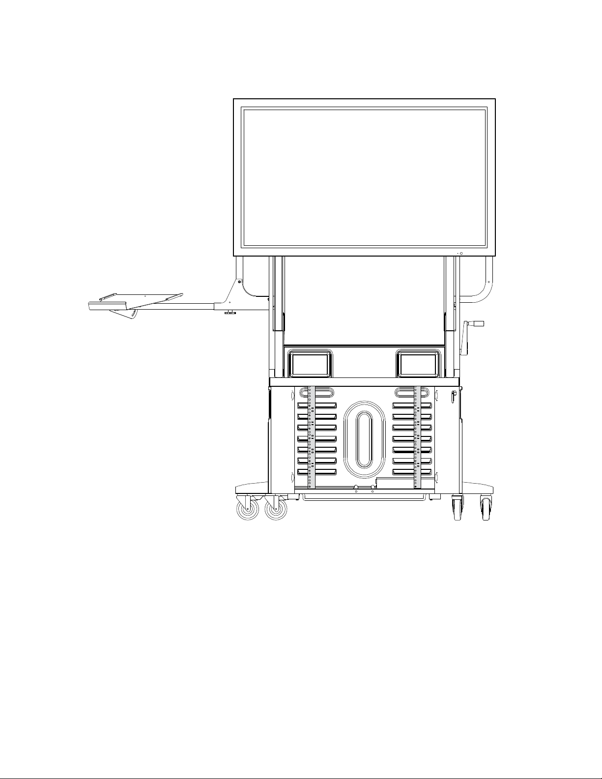
SMART Mobile Stand from the Front
Optional Laptop Shelf
• Mounts on Either Side
of Your Stand
• Adjustable Tilt Angle
• Telescopes Outward
High-Quality,
Integrated Speakers
Locking Cabinet
for Secure Storage
Hydraulic Height
Adjustment Handle
99-00962-20 REV C0
Page 14

4| ABOUT YOUR SMART MOBILE STAND
Large, Removable
Access Panels
SMART Mobile Stand from the Rear
Cabinet Venting
Connection Panel
Serial Number Location
99-00962-20 REV C0
Page 15

5| ABOUT YOUR SMART MOBILE STAND
SMART Mobile Stand from the Rear
(Lower Panel Removed)
Prominent Grab Bars
for Moving Your Unit
Power Management
Adjustable Shelving
Swiveling, Lockable,
Non-Marking Casters
Dedicated Space
for a Computer
Supports Integration
with a SMART Hub
FSSBID 100H Only)
SE240 (Model
99-00962-20 REV C0
Page 16
6| ABOUT YOUR SMART MOBILE STAND
SMART Mobile Stand from the Front with Doors Open
Showing Rack Mount Configuration
99-00962-20 REV C0
Page 17

7| ABOUT YOUR SMART MOBILE STAND
Power Specifications
Your SMART Mobile Stand’s user friendly power management design
accommodates up to 1.2 kW and includes the following features:
• A country-specific power bar—North America (NEMA) 110V AC
or IEC 240V, 50 Hz—which provides power access for additional devices
near the bottom rear of your stand
• An 8' (2.44 m) country-specific power cord (international only)
• A country-specific extension cable
• Country-specific power adapters
• A USB 2.0 cable
Hardware and Internet Connection Requirements
Computer Hardware
You need at least three USB receptacles (recommended) on your computer
to connect it to your SMART Mobile Stand. If your computer has fewer than three
available USB receptacles, you need a USB hub (not included) to connect
your computer to your stand.
Local Area Network (LAN) Connection (Optional)
Your SMART Mobile Stand includes a standard RJ45 LAN connection point
to connect your computer to your network. You need an external source so that
you can access the Internet.
Determining Your Model of SMART Mobile Stand
Your SMART Mobile Stand is either a standard model (FSSBID 100), or one that
includes support for a SMART Hub SE240 (FSSBID 100H). You can determine your
model of SMART Mobile Stand by referring to its serial number, which is located on
the back, right-hand side of your unit’s speaker panel, near the top:
• If you have model FSSBID 100, the serial number follows the format
FSSBID1-R2-XXXXX, where X is any number.
• If you have model FSSBID 100H, the serial number follows the format
FSSBID1H-R2-XXXXX, where X is any number.
99-00962-20 REV C0
Page 18
8| ABOUT YOUR SMART MOBILE STAND
Optional Accessories
Contact your authorized SMAR T reseller to order an y of the following accessory p art s.
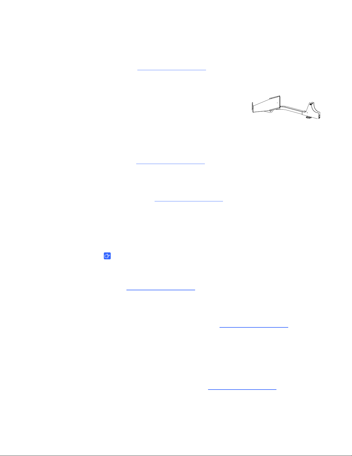
Optional Laptop Shelf
You can order a dedicated laptop shelf if you want to
connect a laptop computer to your SMART Mobile Stand.
This shelf is designed to mount on either side of your
stand, and features an adjustable tilt angle of up to
35 degrees from horizontal. It telescopes outward to accommodate
flat-panel displays ranging from 50" (127 cm) to 65" (165.1 cm) in size.
For more information on ordering a laptop shelf for your SMART Mobile Stand,
contact your authorized SMART reseller
Flat-Panel Display Adapter Kits
Some models of flat-panel displays require audio/vide o ad a pt ers , whic h yo u can
purchase from your authorized SMART reseller
of adapter required for your flat-panel display.
.
. Your reseller can identify the type
SMART Board for Flat-Panel Displays Interactive Overlay Adapter Kit (FSSBID 100 Only)
IMPORTANT
If you intend to use a SMART Board for Flat-Panel Displays interactive overlay
with your SMART Mobile Stand model FSSBID 100, you must purchase a
USB B to USB A adapter AD09 (Part No. ADP USB AB) from
your authorized SMART reseller
.
Rack Mount Hardware Accessory Kit
If you want to configure your SMART Mobile Stand for a rack mount, you can
purchase a hardware accessory kit from your authorized SMART reseller
This kit includes 16 rack clips so that you can mount up to four peripheral racks.
.
Standard Replaceable Parts
If your SMART Mobile Stand requires replacement parts, make sure that the service
technician uses replacement parts specified by SMART Technologies.
To order replacement parts, contact your authorized SMART reseller
.
99-00962-20 REV C0
Page 19
9| ASSEMBLING YOUR SMART MOBILE STAND
Assembling Your SMART Mobile Stand
Your SMART Mobile Stand requi res minimal assembly.
Consult the SMART Mobile Stand for Interactive Displays
Textless Installation Instructions (docu m en t 13 22 9 3
at www.smarttech.com/support
for instructions on installing your SMART Mobile Stand.
WARNING
Failure to follow the installation instructions included with your
SMART Mobile Stand for Interactive Displays could result in personal injury
or product damage.
) included with your unit
CAUTION
Make sure that the weight of your flat-panel display is minimum 80 lb. (36.3 kg)
and maximum 160 lb. (72.6 kg). For a list of flat-panel displays supported
by your SMART Mobile Stand, see
http://www2.smarttech.com/st/en-US/Support/FlatPanel/MobileStandPanels
This chapter includes additional information and tips to consider when you install
your SMART Mobile Stand. Topics include:
• Environmental Requirement s (page 10)
• Things to Consider When Assembling Your SMART Mobile Stand (page 11)
• Installing Your Flat-Panel Display on Your SMART Mobile Stand (page 12)
– Securing the Clevis Pins When Installing a 60" (152 cm) or Larger
Flat-Panel Display (page 13)
• Adjusting the Shelves (page 14)
.
99-00962-20 REV C0
Page 20
10 | ASSEMBLING YOUR SMA RT MOBILE STAND
Environmental Requirements
Before installing your SMART Mobile Stand, refer to the following
environmental requirements.
CAUTION
• Never operate your SMART Mobile Stand immediately after moving it
from a cold location to a warm location. Allow the unit to reach room
temperature before operation to prevent possible product damage.
• Do not place your SMART Mobile Stand in hot locations, such as near
heating equipment.
• Do not block the ventilation slots and openings on your SMART Mob ile S t and.
Blocking these openings could cause overheating and damage to the unit.
Environmental Requirement Parameter
Operating Temperature 41°F to 86°F (5°C to 30°C)
Storage Temperature -40°F to 140°F (-40°C to 60°C)
Humidity 5–80% relative humidity, non-condensing
Water and Fluid Resistance • Intended for indoor use
• Don’t pour or spray liquids directly
on the electronic components.
Dust • Moderate dust
• Designed for pollution degree 1 (P1)
as per EN61558-1, which is defined
as “No pollution or only dry
non-conductive pollution”
• Refer to page 67 for instructions
on periodically cleaning your
SMART Mobile Stand.
Conducted and Radiated Emissions EN55022/CISPR 22, Class B
Flammability Rating • Plastics: HB
• USB 2.0 cable: UL VW-1/CSA FT4
Quality Assembly • USB cable: IPC/WHMA-A-620 Class 2
workmanship standards for
Requirements & Acceptance for Cable
& Wire Harness
99-00962-20 REV C0
Page 21

11 | ASSEMBLING YOUR SMA RT MOBILE STAND
Things to Consider When Assembling Y our SMART Mobile Stand
WARNING
• Two people are required to safely assemble your SMART Mobile Stand
and to mount or remove your flat-panel display and your SMART Board
interactive display frame or SMART Board for Flat-Panel Displays
interactive overlay.
• Lock the casters before installing or working with your flat-panel display
on your SMART Mobile Stand, or adjusting its height.
• To prevent injury, be aware of crush and pinch locations on the product
(marked with the crush symbol) during assembly and use.
• Do not rest your hand on the stand’ s universal mount or under the interactive
product’s pen tray or pencil ledge while adjusting the height of your
SMART Mobile Stand.
• Use the SMART Mobile Stand’s three grab bars to move the unit.
Do not press, pull or push on the flat-panel display, interactive overlay
or display frame, cabinet, doors, rear access panel plastics or
vertical brackets.
• Before moving your SMART Mobile Stand, make sure that you unlock the
casters. These casters are designed to roll on common indoor surfaces.
While you move the unit, your view may be partially obstructed.
Be aware of surrounding obstacles.
CAUTION
To prevent damage to your power and extender cables, secure them to your
mobile floor stand as instructed in the SMART Mobile Stand for Interactive
Displays Textless Installation Instructions (document 132293
at www.smarttech.com/support
NOTES
• You will require ample work space to assemble your SMART Mobile Stand.
• Do not set up or use your SMART Mobile Stand in an area with excessive
levels of dust, dirt, humidity or smoke.
).
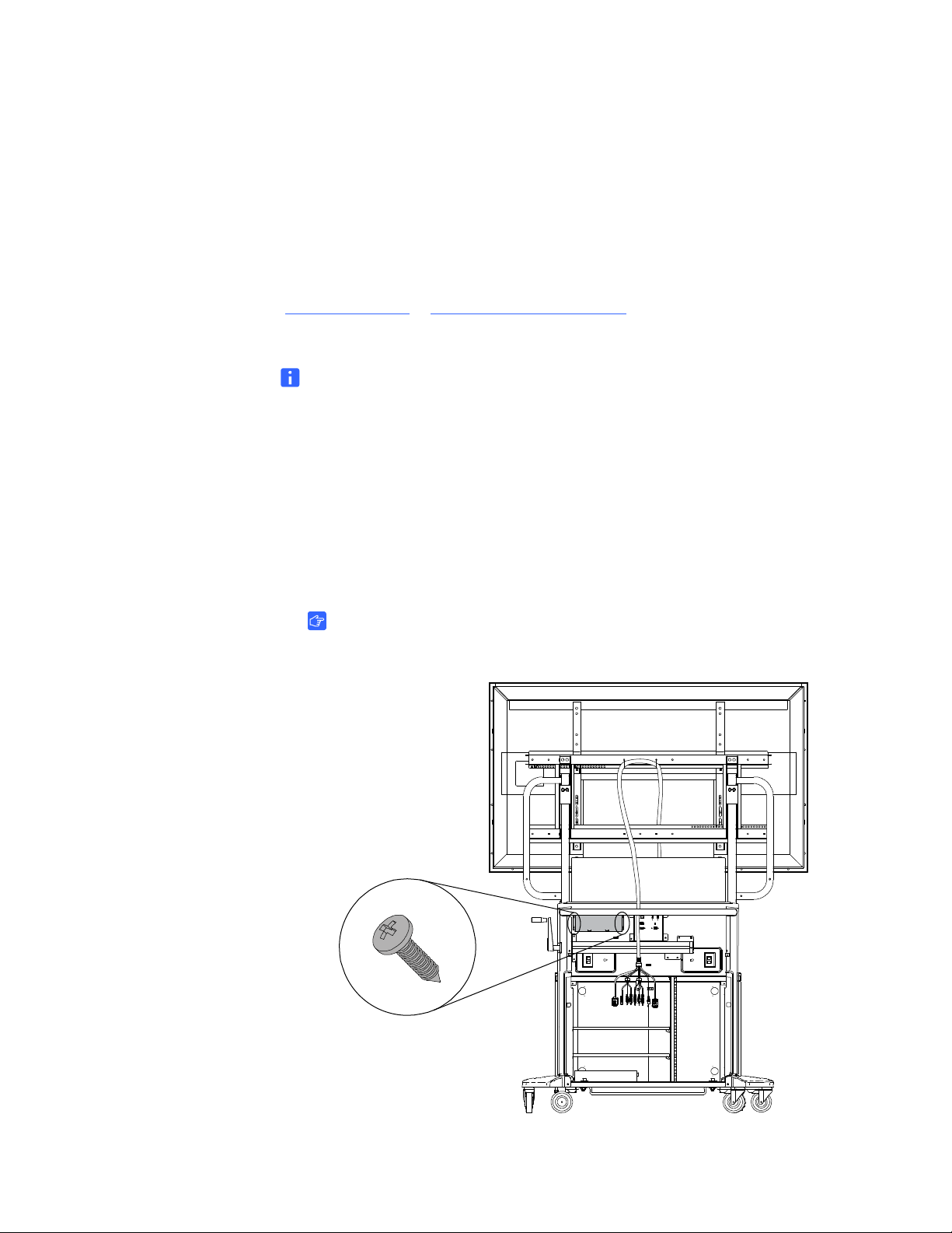
• If you received an IEC power bar with your SMART Mobile Stand and you
need to ground this power bar, use a self-tapping screw (not included)
to secure its ground wire to the base she et met al of your st and. Use the small
hole located on the right side of the power bar (when viewed from the back)
for this purpose.
99-00962-20 REV C0
Page 22
12 | ASSEMBLING YOUR SMA RT MOBILE STAND
Installing Your Flat-Panel Display on Your SMART Mobile Stand
WARNING
• Read the installation instructions published by your flat-panel display’s
manufacturer before installing your flat-panel display on your
SMART Mobile Stand.
• Make sure that you properly engage and secure the vertical brackets both
to your flat-panel display and to your SMART Mobile Stand as instructed
in the SMART Mobile Stand for Interactive Displays Textless Installation
Instructions (document 132293
CAUTION
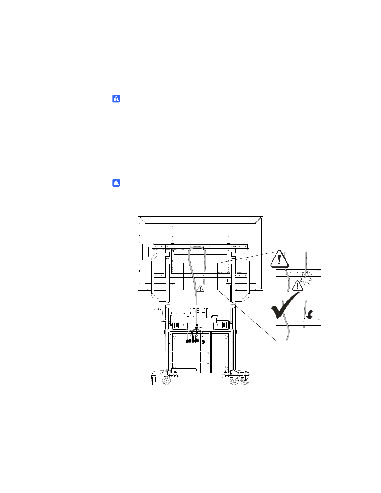
To prevent crushing additional product cables between your flat-panel display
and the SMART Mobile Stand’s speaker panel, follow the path of the installed
cable harness.
at www.smarttech.com/support).
99-00962-20 REV C0
Page 23
13 | ASSEMBLING YOUR SMA RT MOBILE STAND
Securing the Clevis Pins When Installing a 60" (152 cm) or Larger Flat-Panel Display
Follow these instructions if you intend to install a SMART Board for Flat-Panel
Displays interactive overlay with a 60" (152.4 cm) or larger flat-panel display.
CAUTION
To prevent damage to a 60" (152.4 cm) or larger flat-panel display when
it is installed with a SMART Board for Flat-Panel Displays interactive overlay,
make sure that you install the included clevis pin as instructed in this guide.
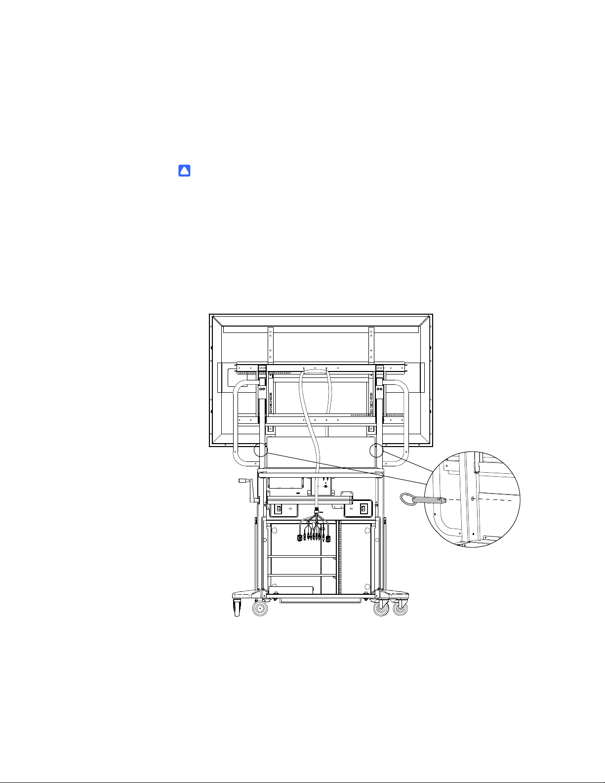
To secure the two
included clevis pins
1. Rotate your SMART Mobile Stand’s height-adjustment handle to raise your
flat-panel display to its highest position.
2. Insert each of the two included clevis pins as shown in the following illustration,
making sure that the clevis pin ring faces outward.
99-00962-20 REV C0
Page 24

14 | ASSEMBLING YOUR SMA RT MOBILE STAND
Adjusting the Shelves
Your SMART Mobile Stand includes two vertically adjustable shelves. The spacing
of these shelves ranges from 2" to 19" (5.1 cm to 48.3 cm). Consider whethe r you plan
to install a SMART Hub, DVD/Blu-ray player or VCR in your unit when determining
the best height for these shelves. Typically, you will install your DVD/Blu-ray player on
the top shelf, and then install your VCR on the bottom shelf.
TIP
If you ordered model FSSBID 100H, install your SMART Hub SE240
(see page 38) in your SMART Mobile Stand before you install the shelves.
To determine your model of stand, see page 7.
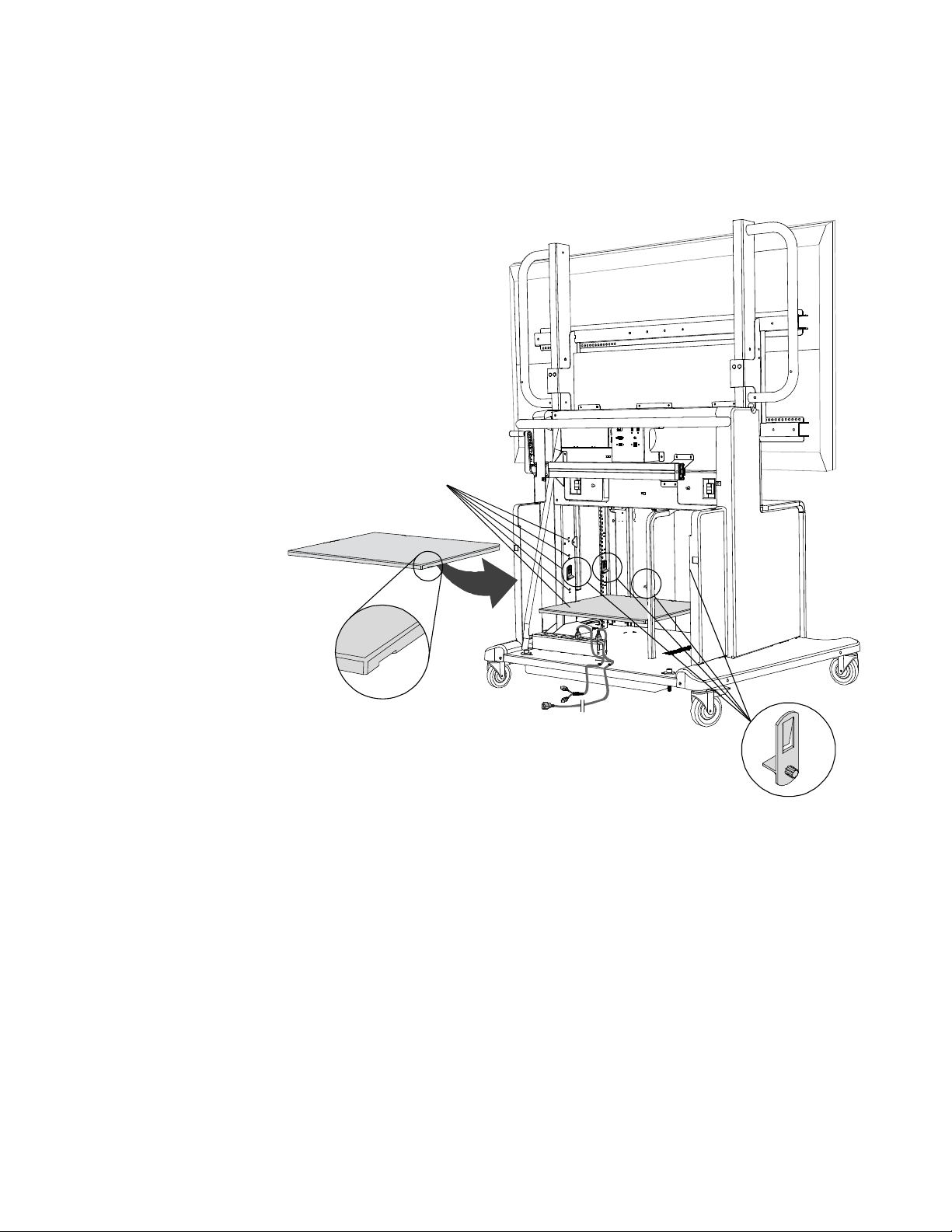
To ad ju s t th e sh e lv in g in
your SMART Mobile Stand
1. If the shelves are already installed in your SMART Mobile Stand, remove them
from the cabinet, and then remove the eight shelf clips.
NOTE
If you need instructions for removing your rear access panels,
see steps 1 to 3 in Appendix A: Configuring a Rack Mount on page 69
(or the SMART Mobile Stand for Interactive Displays Textless Installation
Instructions (document 132293
2. Install four of the included shelf clips at the desired height for the first shelf.
IMPORTANT
– These clips secure to the cabinet’s left and right front rack rails,
rear support tubing and side wall, as shown in the following illustration.
– Ensure that you leave at least 1" (2.5 cm) of space above equipment
for cooling.
at www.smarttech.com/support).
99-00962-20 REV C0
Page 25
15 | ASSEMBLING YOUR SMA RT MOBILE STAND
Five Installation Heights
3. Slide the shelf onto the shelf clips, making sure to position the grooves
on the bottom of the shelf so that it snaps in place.
4. Repeat steps 2 and 3 for your second shelf.
99-00962-20 REV C0
Page 26

16 | ASSEMBLING YOUR SMA RT MOBILE STAND
99-00962-20 REV C0
Page 27

17 | MODEL FSSBID 100: CONNECTING DEVICES INSIDE YOUR SM ART MOBILE
STAND’S CABINET
Model FSSBID 100: Connecting Devices Inside Your SMART Mobile Stand’s Cabinet
This chapter explains how to connect your SMART Mobile Stand FSSBID 100’s
prewired cable harness to your flat-panel display, computer or SMART Hub PE260,
and other devices inside your stand’s cabinet. Your stand’s cable harness provides
centralized cable management with strain relief.
IMPORTANT
Some flat-panel displays require adapter kits, which you can purchase
from your authorized SMART reseller
This chapter covers:
• Connecting Your Flat-Panel Display (page 18)
• Connecting Your Computer (page 21)
• Connecting Your SMART Hub PE260 (page 23)
• Connecting a DVD/Blu-ray Player or VCR (page 25)
• Connecting Your SMART Board interactive display frame (page 28)
• Connecting Your SMART Board for Flat-Panel Displays Interactive Overlay
(page 32)
.
99-00962-20 REV C0
Page 28
18 | MODEL FSSBID 100: CONNECTING DEVICES INSIDE YOUR SM ART MOBILE
P
r
e
w
i
r
e
d
t
o
Y
o
u
r
S
M
A
R
T
M
o
b
i
l
e
S
t
a
n
d
’
s
L
e
f
t
a
n
d
R
i
g
h
t
S
p
e
a
k
e
r
s
T
o
Y
o
u
r
C
o
m
p
u
t
e
r
o
r
S
M
A
R
T
H
u
b
P
E
2
6
0
T
o
Y
o
u
r
S
e
c
o
n
d
S
h
e
l
f
D
e
v
i
c
e
,
e
.
g
.
,
V
C
R
P
r
e
w
i
r
e
d
t
o
Y
o
u
r
S
M
A
R
T
M
o
b
i
l
e
S
t
a
n
d
’
s
C
o
n
n
e
c
t
i
o
n
P
a
n
e
l
T
o
Y
o
u
r
F
i
r
s
t
S
h
e
l
f
D
e
v
i
c
e
,
e
.
g
.
,
D
V
D
P
l
a
y
e
r
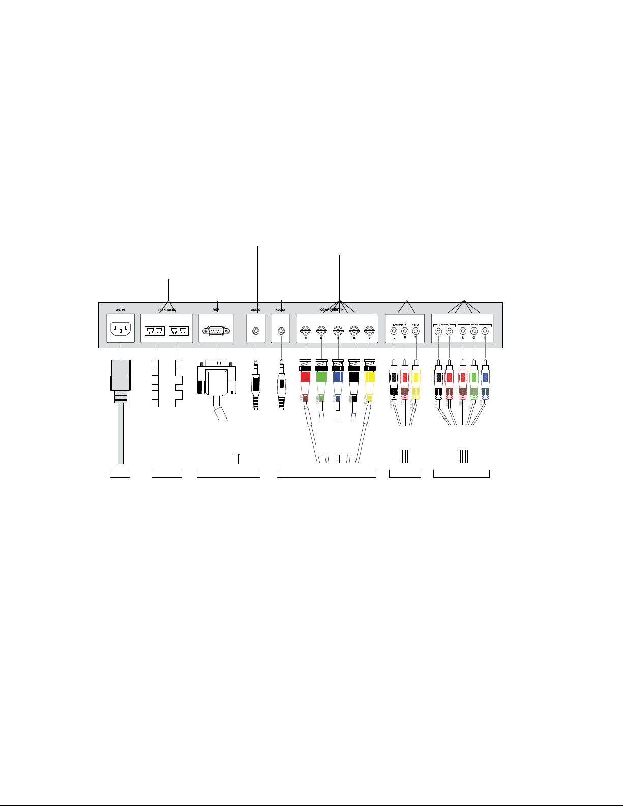
Speaker
Cable
Receptacles
(Output to
Prewired
Speakers)
3.5 mm Stereo
Audio In from
Your Computer
VGA
(Video) In
from Your
Computer
Stereo Audio
and RGB or
Component
Video RCA
Inputs from
an External
Device, e.g.,
DVD Player
Stereo Audio
and
Composite
Video RCA
Inputs from
an External
Device,
e.g., VCR
3.5 mm Stereo
Audio In
(from the
Connection Panel)
BNC Connections
for RGB HV Video
Input (from the
Connection Panel)
5 × RCA
Cable AV03
3.5 mm
Stereo
Audio
Cable
A01
3.5 mm
Stereo
Audio
Cable
AV01
VGA
Cable
AV01
Speaker
Cables
A02
and
A03
5 × BNC
(RGB HV)
Cable V01
3 × RCA
Cable AV02
T
o
Y
o
u
r
S
M
A
R
T
M
o
b
i
l
e
S
t
a
n
d
’
s
P
o
w
e
r
B
a
r
STAND’S CABINET
Connecting Your Flat-Panel Display
Follow these instructions to connect the correct cables from your FSSBID 100’s
prewired cable harness to your flat-panel display’s connection panel.
Cable Connections to Your Flat-Panel Display
99-00962-20 REV C0
Page 29

19 | MODEL FSSBID 100: CONNECTING DEVICES INSIDE YOUR SM ART MOBILE
STAND’S CABINET
To connect your
flat-panel display
1. Connect speaker cables A02 and A03 to your flat-panel display’s
speaker receptacles.
2. Connect the VGA video plug from cable AV01 to your flat-panel display’s VGA
video receptacle.
NOTE
If your flat-panel display has more than one VGA video receptacle, use
the receptacle adjacent or closest to a 3.5 mm audio receptacle.
3. Connect the 3.5 mm stereo audio plug from cable AV01 to an audio receptacle
on your flat-panel display’s connection panel. Typically, this audio receptacle
is beside the VGA connection.
4. Connect the 3.5 mm stereo audio plug from cable A01 to a second audio
receptacle on your flat-panel display’s connection panel.
NOTE
If your flat-panel display’s connection panel has only one 3.5 mm audio
receptacle, contact your authorized SMART reseller
to purchase
a 3.5 mm audio Y- ad ap te r ca ble .
5. Connect cable V01 as follows:
– Connect the red BNC plug to the red BNC receptacle on your flat-panel
display’s connection panel. This receptacle is typically labeled R.
– Connect the green BNC plug to the green BNC receptacle on your flat-panel
display’s connection panel. This receptacle is typically labeled G.
– Connect the blue BNC plug to the blue BNC receptacle on your flat-panel
display’s connection panel. This receptacle is typically labeled B.
– Connect the white BNC plug to the white BNC receptacle on your flat-panel
display’s connection panel. This receptacle is typically labeled H.
– Connect the yellow BNC plug to the yellow BNC receptacle on your flat-panel
display’s connection panel. This receptacle is typically labeled V.
6. Connect cable AV02 as follows:
– Connect the yellow plug to the yellow RCA receptacle on your flat-panel
display’s connection panel. This receptacle is typically labeled V or VIDEO.
– Connect the red plug to the adjacent red RCA receptacle on your flat-panel
display’s connection panel. This receptacle is typically labeled R.
– Connect the white plug to the adjacent white RCA receptacle on your
flat-panel display’s connection pan el. This receptacle is typically labeled L.
99-00962-20 REV C0
Page 30

20 | MODEL FSSBID 100: CONNECTING DEVICES INSIDE YOUR SM ART MOBILE
STAND’S CABINET
7. Connect cable AV03 as follows:
– Connect the RGB red video plug to the appropriate red RCA receptacle
on your flat-panel display’s connection panel. This receptacle is typically
labeled Pr or R.
IMPORTANT
Do not confuse the RGB red video plug with the red audio plug.
– Connect the RGB green video plug to the green RCA receptacle on your
flat-panel display’s connection pan el. This receptacle is typically labeled
Pb or B.
– Connect the RGB blue video plug to the blue RCA receptacle on your
flat-panel display’s connection pan el. This receptacle is typically labeled
Y or G.
– Connect the red audio plug to the remaining red RCA receptacle on your
flat-panel display’s connection pan el. This receptacle is typically
labeled R.
– Connect the white audio plug to the remaining white RCA receptacle on your
flat-panel display’s connection pan el. This receptacle is typically labeled L.
8. Connect your SMART Mobile Stand’s prewired power cable to your flat-panel
display’s power receptacle.
9. Connect the other end of this cable to an available receptacle on your
SMART Mobile S tand’s power bar.
IMPORTANT
• Your flat-panel display won’t look exactly like the one shown on page 18.
• Some flat-panel displays require audio/video adapters, which you can
purchase from your authorized SMART reseller
.
• If you intend to install a Blu-ray player, you can purchase a separate HDMI
cable to replace cable AV03. Install this HDMI cable along the same path
as cable AV03, and then connect it to similar points.
NOTE
Don’t connect your SMART Mobile Stand to a power outlet before you install
the rear access panels (page 58).
99-00962-20 REV C0
Page 31

21 | MODEL FSSBID 100: CONNECTING DEVICES INSIDE YOUR SM ART MOBILE
NOTES
• The VGA male cable and the 3.5 mm stereo audio cable are joined
and marked AV01 in the prewired cable harness.
• You previously connected the other end of these cables to your
flat-panel display (page 19).
VGA (Video) Male Cable
3.5 mm Stereo Audio Plug
Three USB A Male Plugs
Marked C01, C02 and C03
(Prewired to Your SMART Mobile Stand’s
Connection Panel)
RJ45 Male Plug
Marked N01
(Prewired to Your SMART Mobile Stand’s
Connection Panel)
STAND’S CABINET
Connecting Your Computer
Your SMART Mobile Stand includes dedicated space for a tower computer
behind the left cabinet door when your stand is configured for standard shelving.
Internal connections provide support for VGA video, 3.5 mm stereo audio,
USB for interactive product touch control, and two additional USB devices.
WARNING
You must connect the USB cable that came with your SMART Mobile Stand
to a computer that has a USB 2.0 compliant interface and that bears the
USB logo. In addition, the USB source computer must be compliant with
CSA/UL/EN 60950 and bear the CE mark and CSA and/or UL Mark(s)
for CAS/UL 60950. This is for operating safety.
IMPORTANT
SMART recommends that you have at least three USB receptacles on your
computer to connect it to your SMART Mobile Stand. If your computer has fewer
than three available USB receptacles, you need a USB hub (not included)
to connect your computer to your stand. Contact yo ur a uthorized SMART reseller
to order a recommended USB hub.
The following procedure refers to these cables, which are prewired and included
in your SMART Mobile Stand’s cable harness:
99-00962-20 REV C0
Page 32

22 | MODEL FSSBID 100: CONNECTING DEVICES INSIDE YOUR SM ART MOBILE
STAND’S CABINET
To connect to
your computer
1. Connect the VGA video plug from cable AV01 in the prewired cable harness
to your computer’s VGA video receptacle.
NOTES
– Your computer might have more than one VGA video receptacle.
If this is the case, refer to the documentation included with your computer
to determine the correct receptacle.
– If your computer has only DVI receptacles, you likely received a DVI
to VGA adapter (or video card) with your computer, which enables you
to use the DVI connection. If you require a DVI to VGA adapter, you can
purchase one from an electronics or computer store.
2. Connect the 3.5 mm stereo audio plug from cable AV01 in the pr ew ire d cab l e
harness to your computer’s audio output receptacle.
NOTES
– This audio receptacle is typically green, and is often marked with an insert
arrow or the audio waves symbol . If you’re unable to locate this
receptacle, refer to the documentation included with your computer
for more information.
– You previously connected the other end of this cable to your
flat-panel display (see page 19).
3. Connect each of the three USB A male plugs from cables C01, C02
and C03 in the prewired cable harness to an available USB receptacle
on your computer.
OR
If your computer has only two available USB recept acles, connect the A male plug
from the USB cable marked C01 to one receptacle, connect a USB hub (not
included) to the second receptacle, and then connect the A male plugs from the
USB cables marked C02 and C03 to the USB hub.
OR
If your computer has only one available USB receptacle, connect a USB hub
(not included) to the receptacle, and then connect all three USB A male plugs to
the USB hub.
NOTE
If you require a USB hub to connect cables C01, C02 and C03 to your
computer, your authorized SMART reseller
can recommend a part.
4. Connect RJ45 cable N01 to your computer’s network/LAN receptacle .
99-00962-20 REV C0
Page 33

23 | MODEL FSSBID 100: CONNECTING DEVICES INSIDE YOUR SM ART MOBILE
5. Connect your computer’s power cable (not included with your
STAND’S CABINET
SMART Mobile Stand) to an available receptacle on your stand’s power bar.
TIP
Coil and bundle the cable with the included hook-and-loop fastener strap.
Connecting Your SMART Hub PE260
If you connect your SMART Mobile Stand to a SMART Hub PE260 instead of
a computer, install your SMART Hub PE260 in the dedicated space for a tower
computer behind the left cabinet door (when your stand is configured for
standard shelving).
For more information about using your SMART Hub PE260, refer to the SMART Hub
PE260 Configuration Guide (document 127260
NOTE
If you want to connect a SMART Hub SE240 to your SMART Mobile Stand,
contact your authorized SMART reseller
at www.smarttech.com/support).
for more information.
To connect your
SMART Mobile Stand
to a SMART Hub PE260
1. Follow the installation instructions included in the SMART Hub PE260 Textless
Installation Instructions (document 127261
TIP
You might find it easier to complete this connection procedure before
securing your SMART Hub PE260 to your SMART Mobile Stand’s cabinet.
2. Connect the VGA video plug from cable AV01 in the prewired cable harness
to your SMART Hub’s VGA video receptacle, marked Primary.
NOTE
You previously connected the other end of this cable to your
flat-panel display (see page 19).
3. Connect the 3.5 mm stereo audio plug from cable AV01 in the pr ew ire d
cable harness to your SMART Hub’s audio input receptacle, marked
with the audio waves symbol .
4. Connect each of the three USB A male plugs from cables C01, C02
and C03 in the prewired cable harness to an available USB receptacle
on your SMART Hub, marked with the USB symbol .
5. Connect RJ45 cable N01 to your SMART Hub’s network/LAN receptacle 1 .
at www.smarttech.com/support).
6. Connect your SMART Hub’s power cable (included with your SMART Hub PE260)
to an available receptacle on your SMART Mobile Stand’s power bar.
99-00962-20 REV C0
Page 34

24 | MODEL FSSBID 100: CONNECTING DEVICES INSIDE YOUR SM ART MOBILE
P
r
e
w
i
r
e
d
t
o
Y
o
u
r
S
M
A
R
T
M
o
b
i
l
e
S
t
a
n
d
’s
C
o
n
n
e
c
t
i
o
n
P
a
n
e
l
T
o
Y
o
u
r
S
M
A
R
T
M
o
b
i
l
e
S
t
a
n
d
’
s
P
o
w
e
r
B
a
r
T
o
Y
o
u
r
F
l
a
t
-
P
a
n
e
l
D
i
s
p
l
a
y
’
s
C
o
n
n
e
c
t
i
o
n
P
a
n
e
l
P
r
e
w
i
r
e
d
t
o
Y
o
u
r
S
M
A
R
T
M
o
b
i
l
e
S
t
a
n
d
’s
C
o
n
n
e
c
t
i
o
n
P
a
n
e
l
3.5 mm
Stereo
Audio
Cable
AV01
VGA
Cable
AV01
RJ45
Cable
N01
USB
Cable
C01
USB
Cable
C02
USB
Cable
C03
STAND’S CABINET
TIP
Coil and bundle the cable with the included hook-and-loop fastener strap.
NOTE
Don’t connect your SMART Mobile Stand to a power outlet before you install
the rear access panels (page 58).
Cable Connections to Your SMART Hub PE260
99-00962-20 REV C0
Page 35

25 | MODEL FSSBID 100: CONNECTING DEVICES INSIDE YOUR SM ART MOBILE
STAND’S CABINET
Connecting a DVD/Blu-ray Player or VCR
Your SMART Mobile Stand supports audiovisual devices, including a DVD/Blu-ray
player or VCR. Internal connections provide support for a component video device
with stereo audio, and a composite video device with stere o audio.
CAUTION
If you install additional audio or video cables other than those pr ovided with your
SMART Mobile Stand, SMART Board interactive display frame, SMART Board
for Flat-Panel Displays interactive overlay, or as part of an adapter kit, SMART
assumes no responsibility and you are solely responsible for any damage
incurred to your SMART Mobile Stand, its cabling or other devices.
IMPORTANT
• The following procedures are generic instructions, and your DVD or Blu-ray
player or VCR’s connection panel might not resemble the illustrations or color
codes referenced in this guide. Refer to the documentation included with your
device for specific connection instructions.
• For some DVD and Blu-ray players, you might choose to purchase a separate
HDMI cable to replace cable AV03. Install this HDMI cable along the same
path as cable AV03. See page 12 for details on connecting the other end of
this cable to your flat-panel display.
TIPS
• Install your DVD or Blu-ray player on the top shelf or highest rack mount
position in your SMART Mobile Stand’s cabinet.
• Install your VCR on the lowest shelf in your SMART Mobile Stand’s cabinet.
99-00962-20 REV C0
Page 36

26 | MODEL FSSBID 100: CONNECTING DEVICES INSIDE YOUR SM ART MOBILE
Cable
AV03
STAND’S CABINET
To connect your
DVD/Blu-ray player
1. Connect the five-plug RCA cable AV03, or your
HDMI cable, as follows:
– Connect the RGB red video plug to your DVD
or Blu-ray player’s appropriate red receptacle,
which is typically labeled Pr or R.
IMPORTANT
Do not confuse the RGB red video plug
with the red audio plug.
– Connect the RGB blue video plug to your DVD
or Blu-ray player’s blue receptacle, which is
typically labeled Pb or B.
– Connect the RGB green video plug to your
DVD or Blu-ray player’s green receptacle,
which is typically labeled Y or G.
– Connect the red audio plug to your DVD or Blu-ray player’s remaining red
receptacle, which is typically labeled R.
– Connect the white audio plug to your DVD or Blu-ray player’s white
receptacle, which is typically labeled L.
NOTE
You previously connected the other end of this cable to your
flat-panel display (see page 20).
2. Connect your DVD or Blu-ray player’s power cable (not included with your
SMART Mobile Stand) to an available receptacle on your SMART Mobile Stand’s
power bar.
TIP
Coil and bundle the cable with the included hook-and-loop fastener strap.
NOTE
Don’t connect your SMART Mobile Stand to a power outlet before you install
the rear access panels (page 58).
99-00962-20 REV C0
Page 37

27 | MODEL FSSBID 100: CONNECTING DEVICES INSIDE YOUR SM ART MOBILE
Cable
AV02
STAND’S CABINET
To connect
your VCR
1. Connect the three-plug RCA cable AV02 as follows:
– Connect the yellow plug to your VCR’s yellow
receptacle, which is typically labeled V or VIDEO.
– Connect the red audio plug to your VCR’s
appropriate red receptacle, which is typically
labeled R.
– Connect the white audio plug to your VCR’s
appropriate white receptacle, which is typically
labeled L.
NOTE
You previously connected the other end of this cable
to your flat-panel display (see page 19).
2. Connect your VCR’s power cable (not included) to an available receptacle
on your SMART Mobile Stand’s power bar.
TIP
Coil and bundle the cable with the included hook-and-loop fastener strap.
NOTE
Don’t connect your SMART Mobile Stand to a power outlet before you install
the rear access panels (page 58).
99-00962-20 REV C0
Page 38
28 | MODEL FSSBID 100: CONNECTING DEVICES INSIDE YOUR SM ART MOBILE
STAND’S CABINET
Connecting Your SMART Board interactive display frame
This section describes how to connect your SMART Board interactive display frame’s
controller box to your SMART Mobile Stand (instead of directly to a computer).
Refer to the SMART Board interactive display frame Installation and User’s Guide
(document 125254
on installing your SMART Board interactive display frame on your flat-panel display.
NOTE
You don’t need the USB cable included with your SMART Board interactive
display frame to complete the following procedure.
at www.smarttech.com/support) for general instructions
To connect your
interactive display frame
1. Rotate your SMART Mobile Stand’s height-adjustment handle to raise
your flat-panel display to its highest position.
2. Working inside your SMART Mobile Stand’s cabinet from the back, secure your
SMART Board interactive display frame’s controller box to the mounting ho les
on the left side of the connection panel with the four screws included in your
stand’s accessory kit.
IMPORTANT
Ensure that the controller box’s LEDs face downward.
99-00962-20 REV C0
Page 39

29 | MODEL FSSBID 100: CONNECTING DEVICES INSIDE YOUR SM ART MOBILE
USB B Cable C04
STAND’S CABINET
3. Connect your SMART Board interactive display frame’s power cable to your
interactive display frame’s power supply.
4. Connect the cable from your SMART Board interactive display frame’s
power supply to the controller box.
TIP
Route this cable up the cabinet’s rear support tube and behind the hydraulic
pump, leaving enough slack to create a strain relief loop.
5. Connect the other end to an available receptacle on your SMART Mobile Stand’s
power bar, an d then coil and bundle any excess cable.
TIP
Place the power supply’s transformer box next to the power bar, on the floor
of your SMART Mobile Stand’s cabinet.
6. Remove the plastic cable tie from the USB B male cable (marked C04)
in your prewired cable harness, and then connect this cable to the USB r eceptacle
on your interactive display frame’s controller box.
NOTE
The other end of cable C04 is prewired to your SMART Mobile Stand’s
connection panel (which connects to your computer or SMART Hub).
TIP
– Leave enough slack in this cable to create a strain relief loop.
– Use a plastic cable tie to fasten this cable to the clip on the inside
of your SMART Mobile Stand’s speaker panel, as illustrated on page 31.
99-00962-20 REV C0
Page 40

30 | MODEL FSSBID 100: CONNECTING DEVICES INSIDE YOUR SM ART MOBILE
STAND’S CABINET
7. Route your interactive display frame’s camera cables through the connection
panel from the right side, up your SMART Mob ile Stand’s prewired cable harness,
down behind the speaker panel and along the inside edge of the pencil ledge,
as shown page 31.
TIPS
– To route the camera cables, remove the plastic cable ties securing the
cable harness to your SMART Mobile S tan d’s top horizont al mounting bar ,
remove the nylon sleeve, and then loosen all the hook-and-loop
fastener straps.
– Remove each plastic cable tie by pressing down on the plastic tab
while you pull the tie backward.
– After you route the camera cables, secure them together with the rest
of the cables with the hook-and-loop fastener straps and nylon sleeve,
and then secure the cable bundle to the top horizontal mounting bar
with the plastic cables ties.
8. Connect the camera cables to your frame’s bottom corner blocks.
99-00962-20 REV C0
Page 41

31 | MODEL FSSBID 100: CONNECTING DEVICES INSIDE YOUR SM ART MOBILE
Connect USB Cable C04
to the controller box,
creating a strain relief loop,
and then fasten it to a clip
on the speaker panel
with a plastic cable tie.
Coil and fasten the
excess camera cables
to the clips on the
speaker panel
with plastic cable ties.
Power Cable to
Your Controller Box
with Strain Relief Loop
Speaker Panel
Camera
Camera
Route camera cables up
your SMART Mobile Stand’s
prewired cable harness,
down behind the speaker
panel and along the inside
edge of the pencil ledge.
STAND’S CABINET
9. Route the other end of the camera cables back through the connection panel from
right to left, and then connect them to your SMART Board interactive display
frame’s controller box, coiling the excess cable and fastening it to the speaker
panel with cable ties, as shown below.
TIP
Leave some slack throughout the length of these cables. Don’t pull them tight.
Cable Connections to Your SMART Board Interactive Display Frame
99-00962-20 REV C0
Page 42

32 | MODEL FSSBID 100: CONNECTING DEVICES INSIDE YOUR SM ART MOBILE
USB A Female to
USB B Female
Adapter AD09
STAND’S CABINET
IMPORTANT
Ensure that your SMART Board interactive display frame is functioning correctly
before you install the rear access panels on your SMART Mobile Stand
(see page 58). Connect your SMART Mobile Stand temporarily to a power outlet
while you check your interactive display frame.
Connecting Your SMART Board for Flat-Panel Displays Interactive Overlay
This section describes how to connect your SMART Board for Flat-Panel Displays
interactive overlay to your SMART Mobile Stand (instead of directly to a computer).
Refer to the SMART Board for Flat-Panel Displays Installation Guide: Corner Brackets
(document 769
your interactive overlay on your flat-panel display.
at www.smarttech.com/support) for general instructions on installing
IMPORTANT
You need adapter AD09 to install your SMART Board for Flat-Panel Displays
interactive overlay. Purchase this adapter (Part No. ADP USB AB) from your
authorized SMART reseller
.
99-00962-20 REV C0
Page 43

33 | MODEL FSSBID 100: CONNECTING DEVICES INSIDE YOUR SM ART MOBILE
Cable C04
USB A to B Adapter AD09
Power Cable to Your
SMART Board
for Flat-Panel Displays
Interactive Overlay’s
Pen Tray
Power Cable to Power Supply
Coil the DB9 to
USB adapter
cable’s excess
length, fasten it
to a clip on the
speaker panel
with a plastic
cable tie, and
then secure this
adapter cable to
cable C04 with
another plastic
cable tie.
STAND’S CABINET
Cable Connections to Your Interactive Overlay
To connect your
interactive overlay
1. Working inside your SMART Mobile Stand’s cabinet from the back, secure
your interactive overlay’s power supply to the two mounting holes directly
to the right of the connection panel, using plastic cable ties.
IMPORTANT
Position this power supply so that the power cable is on the left side.
2. Connect the power cable and connector from this power supply to your
interactive overlay’s power port.
TIPS
– Route this power cable through your SMART Mobile Stand’s connection
panel and up the prewired cable harness.
– Leave some slack throughout the length of this cable. Don’t pull it tight.
99-00962-20 REV C0
Page 44

34 | MODEL FSSBID 100: CONNECTING DEVICES INSIDE YOUR SM ART MOBILE
USB B Cable C04
STAND’S CABINET
3. Connect the DB9 end of the SMART DB9 to USB adapter cable (included with
your SMART Board for Flat-Panel Displays interactive overlay) to your pen tray,
ensuring that you can still easily access the USB A plug at the other end.
TIPS
– First route this adapter cable through your SMART Mobile Stand’s
connection panel and up the prewired cable harness.
– Leave some slack throughout the length of this cable. Don’t pull it tight.
– Coil the excess cable and fasten it to the lower right clip on your
SMART Mobile Stand’s speaker panel with plastic cable ties.
4. Connect the USB plug that you left accessible in the previous step to the
USB A receptacle of adapter AD09, which you purchased for your
SMART Mobile Stand (as shown on page 32).
NOTE
Don’t connect the SMART DB9 to USB adapter cable included with
your SMART Board for Flat-Panel Displays interactive overlay to your
computer, as instructed in the SMART Board for Flat-Panel Displays
Installation Guide.
5. If you’ve connected either a computer or a SMART Hub
PE260 to your SMART Mobile Stand, remove the plastic
cable tie from the USB B male cable (marked C04) in
your SMART Mobile S ta nd’s prewired cabl e harness, and
then connect it to the other end of the adapter
that you purchased for your unit (as shown on page 32).
NOTE
The other end of cable C04 is prewired to your
SMART Mobile Stand’s connection panel.
TIP
Secure cable C04 to the SMART DB9 to USB adapter cable include d
with your interactive overlay with a plastic cable tie.
6. Connect your interactive overlay’s power cable (included with your interactive
overlay) to the right side of its power supply.
99-00962-20 REV C0
Page 45

35 | MODEL FSSBID 100: CONNECTING DEVICES INSIDE YOUR SM ART MOBILE
STAND’S CABINET
7. Route the power cable through the connection panel from right to left, behind
the hydraulic pump and down the cabinet’s rear support tube, and then connect
the other end to an available receptacle on your SMART Mobile Stand’s
power bar.
TIP
Coil and bundle the excess cable with the included hook-and-loop
fastener strap.
NOTES
• Don’t connect your SMART Mobile Stand to a power outlet before you install
the rear access panels (page 58).
• If you move your SMART Mobile Stand with a SMART Board for Flat-Panel
Displays interactive overlay installed, secure the pens in the pen tray so that
they don’t fall out.
99-00962-20 REV C0
Page 46

36 | MODEL FSSBID 100: CONNECTING DEVICES INSIDE YOUR SM ART MOBILE
STAND’S CABINET
99-00962-20 REV C0
Page 47

37 | MODEL FSSBID 1 00H: CONNECTING DEVICES INSIDE YOUR SMART MOBIL E
STAND’S CABINET
Model FSSBID 100H: Connecting Devices Inside Your SMART Mobile Stand’s Cabinet
This chapter explains how to connect your SMART Mobile Stand FSSBID 100H’s
prewired cable harness to your flat-panel display, SMART Hub SE240, computer,
and other devices inside your stand’s cabinet. Your stand’s cable harness provides
centralized cable management with strain relief.
IMPORTANT
Some flat-panel displays require adapter kits, which you can purchase
from your authorized SMART reseller
This chapter covers:
• Installing Your SMART Hub SE240 (page 38)
• Connecting Your Flat-Panel Display (page 41)
• Connecting Your SMART Hub SE240 (page 43)
• Connecting Your Computer (page 46)
• Connecting a DVD/Blu-ray Player or VCR (page 48)
• Connecting Your SMART Board interactive display frame (page 50)
• Connecting Your SMART Board for Flat-Panel Displays Interactive Overlay
(page 55)
.
99-00962-20 REV C0
Page 48

38 | MODEL FSSBID 1 00H: CONNECTING DEVICES INSIDE YOUR SMART MOBIL E
2×
8×
STAND’S CABINET
Installing Your SMART Hub SE240
Perform the following procedure to install a SMART Hub SE240 in your
FSSBID 100H’s cabinet, using the washers and screws that you received
with your stand.
IMPORTANT
– Do not follow the installation instructions included with your
SMART Hub SE240.
– When you configure your SMART Mobile Stand for a rack mount,
you can also install your SMART Hub SE240 in the top rack mount position
(see Configuring a Rack Mount on page 69).
To install your
SMART Hub SE240
1. If the shelves are already installed in your SMART Mobile Stand, remove them
from the cabinet, and then remove the eight shelf clips.
NOTE
If you need instructions for removing your rear access panels,
see steps 1 to 3 in Appendix A: Configuring a Rack Mount on page 69.
2. Align the base of a SMART Hub SE240 mounting bracket to the top of the
front left corner and rear right corner of your hub (when viewed from its
connection face), as shown in the following image.
99-00962-20 REV C0
Page 49

39 | MODEL FSSBID 1 00H: CONNECTING DEVICES INSIDE YOUR SMART MOBIL E
Pilot Holes
(Drilled in Cabinet’s
Top Panel)
STAND’S CABINET
3. Using a Phillips® No. 2 screwdriver, secure these mounting brackets using four
of the screws included with your SMART Hub SE240, as shown.
NOTE
You don’t need the other two L-brackets and four screws included
with your hub.
4. Working inside your SMART Mobile Stand’s cabinet from the rear, position your
SMART Hub SE240 against the cabinet’s top panel, aligning the holes in the
mounting brackets to the four pilot holes drilled in the top of the cabinet, as sh own.
99-00962-20 REV C0
Page 50

40 | MODEL FSSBID 1 00H: CONNECTING DEVICES INSIDE YOUR SMART MOBIL E
4×
STAND’S CABINET
5. Using a Phillips No. 2 screwdriver, secure your SMART Hub SE240 to your
SMART Mobile Stand’s cabinet with the four washers and four screws included
in your stand’s accessory kit, as shown.
NOTE
Don’t over-tighten these screws.
6. Replace the shelves that you removed in step 1.
TIPS
– Ensure that you leave at least 1" (2.5 cm) of space between equipment
for cooling.
– For more information on adjusting the shelves in your SMART Mobile
Stand’s cabinet, see page 14.
99-00962-20 REV C0
Page 51

41 | MODEL FSSBID 1 00H: CONNECTING DEVICES INSIDE YOUR SMART MOBIL E
P
r
e
w
i
r
e
d
t
o
Y
o
u
r
S
M
A
R
T
M
o
b
i
l
e
S
t
a
n
d
’
s
L
e
f
t
a
n
d
R
i
g
h
t
S
p
e
a
k
e
r
s
T
o
Y
o
u
r
S
M
A
R
T
H
u
b
S
E
2
4
0
Speaker
Cable
Receptacles
(Output to
Prewired
Speakers)
3.5 mm Stereo
Audio In
from Your
SMART Hub
VGA
(Video) In
from Your
SMART
Hub
3.5 mm
Stereo
Audio
Cable
A04
VGA
Cable
V04
Speaker
Cables
A02
and
A03
T
o
Y
o
u
r
S
M
A
R
T
M
o
b
i
l
e
S
t
a
n
d
’
s
P
o
w
e
r
B
a
r
T
o
Y
o
u
r
S
M
A
R
T
H
u
b
S
E
2
4
0
STAND’S CABINET
Connecting Your Flat-Panel Display
Follow these instructions to connect the correct cables from your
FSSBID 100H’s prewired cable harness to your flat-panel display’s connection panel.
Cable Connections to Your Flat-Panel Display
99-00962-20 REV C0
Page 52

42 | MODEL FSSBID 1 00H: CONNECTING DEVICES INSIDE YOUR SMART MOBIL E
STAND’S CABINET
To connect your
flat-panel display
1. Connect speaker cables A02 and A03 to your flat-panel display’s
speaker receptacles.
2. Connect the VGA video plug from cable
V04 to your flat-panel display’s
VGA video receptacle.
3. Connect the 3.5 mm stereo audio plug from cable
A04 to an audio receptacle
on your flat-panel display’s connection panel.
4. Connect the SMART Mobile Stand’s prewired power cable to your flat-panel
display’s power receptacle.
5. Connect the other end of this cable to an available receptacle on your
SMART Mobile Stand’s power bar.
IMPORTANT
• Your flat-panel display won’t look exactly like the one shown on page 41.
• Some flat-panel displays require audio/video adapters, which you can
purchase from your authorized SMART reseller
.
• Don’t connect your SMART Mobile Stand to a power outlet before you install
the rear access panels (page 58).
99-00962-20 REV C0
Page 53

43 | MODEL FSSBID 1 00H: CONNECTING DEVICES INSIDE YOUR SMART MOBIL E
L
R
12V DC
Reset
Computer 21 Video InComputer 1
Computer Audio
2
1
Composite
Video
S-video
Audio InLR
Audio In LR
Audio Out USB
Network
RS-232 BA
Video Out
Computer 2
SMART Hub SE240
P
r
e
w
i
r
e
d
t
o
Y
o
u
r
S
M
A
RT
M
o
b
i
l
e
S
t
a
n
d
’
s
C
o
n
n
e
c
t
i
o
n
P
a
n
e
l
T
o
Y
o
u
r
F
l
a
t
-
P
a
n
e
l
D
i
s
p
l
a
y
’
s
C
o
n
n
e
c
t
i
o
n
P
a
n
e
l
P
r
e
w
i
r
e
d
t
o
Y
o
u
r
S
M
A
RT
M
o
b
i
l
e
S
ta
n
d
’
s
C
o
n
n
e
c
t
i
o
n
P
a
n
e
l
T
o
Y
o
u
r
S
M
A
RT
M
o
b
i
l
e
S
t
a
n
d
’
s
P
o
w
e
r
B
a
r
P
r
e
w
i
r
e
d
t
o
Y
o
u
r
S
M
A
RT
M
o
b
i
l
e
S
t
a
n
d
’
s
C
o
n
n
e
c
t
i
o
n
P
a
n
e
l
T
o
Y
o
u
r
C
o
m
p
o
n
e
n
t
D
e
v
i
c
e
,
e
.
g
.
,
D
V
D
P
l
a
y
e
r
P
r
e
w
i
r
e
d
t
o
Y
o
u
r
S
M
A
RT
M
o
b
i
l
e
S
ta
n
d
’
s
C
o
n
n
e
c
t
i
o
n
P
a
n
e
l
I
n
c
l
u
d
e
d
w
i
t
h
Y
o
u
r
I
n
t
e
r
a
c
t
i
v
e
D
i
s
p
l
a
y
F
r
a
m
e
o
r
O
v
e
r
l
a
y
3.5 mm
Stereo
Audio
Cable
A01
3 × RCA
Cable AV02
2 × RCA
Cable A04
USB Cables
C01, C02, C03
USB
Cable
C04
DVI-A Male to
VGA Female
Adapter AD08
S-Video
Male
Cable
V02
RJ45
Cable
N01
DVI Male
Cable V03
T
o
Y
o
u
r
C
o
m
p
u
t
e
r
(
O
p
t
i
o
n
a
l
)
2 × RCA
Cable A05
DVI Male
Cable V04
VGA + 3.5 mm
Stereo Audio
Cable AV05
T
o
Y
o
u
r
F
i
r
s
t
S
h
e
l
f
D
e
v
i
c
e
,
e
.
g
.
,
D
V
D
P
l
a
y
e
r
T
o
Y
o
u
r
F
l
a
t
-
P
a
n
e
l
D
i
s
p
l
a
y
’
s
C
o
n
n
e
c
t
i
o
n
P
a
n
e
l
T
o
Y
o
u
r
C
o
m
p
u
t
e
r
(
O
p
t
i
o
n
a
l
)
P
r
e
w
i
r
e
d
t
o
Y
o
u
r
S
M
A
RT
M
o
b
i
l
e
S
t
a
n
d
’
s
C
o
n
n
e
c
t
i
o
n
P
a
n
e
l
T
o
Y
o
u
r
S
e
c
o
n
d
S
h
e
l
f
D
e
v
i
c
e
,
e
.
g
.
,
V
C
R
STAND’S CABINET
Connecting Your SMART Hub SE240
99-00962-20 REV C0
Page 54

44 | MODEL FSSBID 1 00H: CONNECTING DEVICES INSIDE YOUR SMART MOBIL E
STAND’S CABINET
Perform the following procedure to connect a SMART Hub SE240
to your SMART Mobile Stand.
NOTE
You require a USB A to USB B cable (not included) if you’re installing a computer
with your SMART Hub SE240.
To connect your
SMART Hub SE240
1. Connect the 3.5 stereo audio plug from cable A01 to your SMART Hub’s
Computer Audio receptacle, marked 1.
2. Connect the three-plug RCA cable
AV02 included in your SMART Mobile Stand’s
accessory kit as follows:
– Connect the yellow plug to your SMART Hub’s
Composite Video
RCA receptacle.
– Connect the red plug to the adjacent
– Connect the white plug to the adjacent
3. Connect the two-plug RCA cable
A04 as follows:
– Connect the red plug to your SMART Hub’s
marked
R.
– Connect the white plug to your SMART Hub’s
marked
L.
Audio In RCA receptacle, marked R.
Audio In RCA receptacle, marked L.
Audio Out RCA receptacle,
Audio Out RCA receptacle,
NOTE
You previously connected the other end of this cable to your
flat-panel display (see page 42).
4. Connect the two-plug RCA cable
A05 included in your SMART Mobile Stand’s
accessory kit as follows:
99-00962-20 REV C0
– Connect the red audio plug to your SMART Hub’s remaining
RCA receptacle, marked
R.
– Connect the white audio plug to your SMART Hub’s remaining
RCA receptacle, marked
5. Connect S-Video cable
to your hub’s
6. Connect DVI cable
S-Video receptacle.
V03 in the prewired cable harness inside the cabinet of your
SMART Mobile Stand to your hub’s
7. Connect DVI cable
V04 to your SMART Hub’ s DVI recept acle, m arked V i deo Out.
L.
V02 included in your SMART Mobile Stand’s accessory kit
Video In receptacle (marked Computer 1).
NOTE
You previously connected the other end of this cable to your
flat-panel display (see page 42).
Audio In
Audio In
Page 55

45 | MODEL FSSBID 1 00H: CONNECTING DEVICES INSIDE YOUR SMART MOBIL E
STAND’S CABINET
8. Connect each of the three USB A male plugs from cables C01, C02
C03 in the prewired cable harness inside the cabinet of your
and
SMART Mobile Stand to an available USB A receptacle on your
SMART Hub, marked
USB.
9. Remove the plastic cable tie from the USB B male cable (marked
C04) in your
SMART Mobile Stand’s prewired cable harness, and then connect this cable to
the USB B receptacle marked
Computer 1 on your SMART Hub SE240.
10. If you intend to install a SMART Board interactive display frame on your
SMART Mobile Stand, connect the USB A plug of the USB cable included with
your interactive display frame to an available USB A receptacle
on your SMART Hub SE240.
OR
If you intend to install a SMART Board
for Flat-Panel Displays interactive overlay
with your SMART Mobile Stand, connect the USB A plug of the SMART
DB9 to USB adapter cable included with your interactive overlay to an available
USB A receptacle on your SMART Hub SE240.
TIP
Route the other end of this cable up the cabinet’s rear support tube
and behind the hydraulic pump.
11. Connect RJ45 cable
marked
Network.
N01 to your SMART Hub’s network/LAN receptacle,
If you’re installing a computer with your SMART Hub SE240, complete the
following steps. Otherwise, see
To finish installing your SMART Hub SE240
on page 45.
To connect your
SMART Hub SE240
to a computer
To finish installing
your SMART Hub SE240
1. Connect the DVI A connector of adapter AD08 included with your
SMART Hub SE240 to your SMART Hub’s remaining
(marked
Computer 2), and then connect the VGA video plug from cable AV05
included in your SMART Mobile Stand’s accessory kit to adapter
Video In receptacle
AD08’s
VGA video receptacle.
2. Connect the 3.5 mm stereo audio plug from cable
SE240’s remaining
Computer Audio receptacle, marked 2.
AV05 to your SMART Hub
3. Connect a USB A to USB B cable (not included) to the remaining
USB B receptacle marked
Computer 2 on your hub.
1. Connect your SMART Hub SE240’s power cable (included with your hub)
to the receptacle marked
12V DC, and then connect the other end to a
free receptacle on your SMART Mobile Stand’s power bar.
99-00962-20 REV C0
Page 56

46 | MODEL FSSBID 1 00H: CONNECTING DEVICES INSIDE YOUR SMART MOBIL E
VGA (Video) Male Cable
3.5 mm Stereo Audio Plug
USB A Male Plug
from USB A to USB B Cable
(Not Included)
STAND’S CABINET
TIP
Coil and bundle the cable with the included hook-and-loop fastener strap.
2. Replace the shelves in your SMART Mobile Stand’s cabinet. See page 14
for details on installing the shelves in your SMART Mobile Stand.
Connecting Your Computer
If you choose to install a computer with your SMART Hub SE240, your
SMART Mobile Stand includes dedicated space for a tower computer behind
the left cabinet door when your stand is configured for standard shelving.
Internal connections provide support for VGA video, 3.5 mm stereo audio,
USB for interactive product touch control, and two additional USB devices.
IMPORTANT
• You must connect your SMART Hub SE240 to your computer (page 45)
before you complete the following procedure.
• The following procedure refers to these cables, which you previously
connected to your SMART Hub SE240 (page 43):
NOTE
The VGA male cable and the 3.5 mm stereo audio cable are joined
and marked
AV05.
99-00962-20 REV C0
Page 57

47 | MODEL FSSBID 1 00H: CONNECTING DEVICES INSIDE YOUR SMART MOBIL E
STAND’S CABINET
To connect to
your computer
1. Connect the VGA video plug from cable AV05 to your computer’s VGA
video receptacle.
NOTES
– Your computer might have more than one VGA video receptacle.
If this is the case, refer to the documentation included with your computer
to determine the correct receptacle.
– If your computer has only DVI receptacles, you likely received a DVI
to VGA adapter (or video card) with your computer, which enables you
to use the DVI connection. If you require a DVI to VGA adapter, you can
usually purchase one from an electronics or computer store.
– Y ou previously connected the other end of this cable to your
SMART Hub SE240 (see page 45).
2. Connect the 3.5 mm stereo audio plug from cable
AV05 to your computer’s audio
output receptacle.
NOTE
This audio receptacle is typically green, and is often marked with an insert
arrow or the audio waves symbol . If you’re unable to locate this
receptacle, refer to the documentation included with your computer for
more information.
3. Connect the USB A male plug of the USB A to USB B cable
(not included) that you previously connected to your SMART Hub SE240
to an available USB receptacle on your computer (see page 45).
4. Connect your computer’s power cable (not included with your SMART Mobile
Stand) to an available receptacle on your stand’s power bar.
TIP
Coil and bundle the cable with the included hook-and-loop fastener strap.
99-00962-20 REV C0
Page 58

48 | MODEL FSSBID 1 00H: CONNECTING DEVICES INSIDE YOUR SMART MOBIL E
S-Video
Male
Cable
V02
2 × RCA
Cable A05
STAND’S CABINET
Connecting a DVD/Blu-ray Player or VCR
Your SMART Mobile Stand supports au diovisual devices, including a DVD/Blu-ray
player or VCR. Internal connections provide support for an S-vi deo device with stereo
audio, and a composite video device with stereo audio.
CAUTION
If you install additional audio or video cables other than those provided with your
SMART Mobile S tand, SMART Board interactive display frame, SMART Board
for Flat-Panel Displays interactive overlay, or as part of an adapter kit, SMART
assumes no responsibility and you are solely responsible for any damage
incurred to your SMART Mobile Stand, its cabling or other devices.
IMPORTANT
• The following procedures are generic instructions, and your DVD or Blu-ray
player or VCR’s connection panel might not resemble the illustrations or color
codes referenced in this guide. Refer to the documentation included with your
device for specific connection instructions.
To connect your
DVD/Blu-ray player
• For some DVD and Blu-ray players, you might choose to purchase a separate
HDMI cable to replace cables
the same path as cables
A05 and V02. Install this HDMI cable along
A05 and V02. See page 41 for details on connecting
the other end of these cables to your flat-panel display.
TIPS
• Install your DVD or Blu-ray player on the top shelf, or the second highest
rack mount position.
• Install your VCR on the lowest shelf in your SMART Mobile Stand’s cabinet.
1. Connect the two-plug RCA cable A05, or your HDMI
cable, as follows:
– Connect the red audio plug to your DVD
or Blu-ray player’s appropriate red receptacle,
which is typically labeled
R.
– Connect the white audio plug to your DVD
or Blu-ray player’s white receptacle,
which is typically labeled
L.
NOTE
You previously connected the other end of this
cable to your SMART Hub SE240 (see page44).
99-00962-20 REV C0
2. Connect S-Video cable
V02 to the appropriate receptacle on your DVD
or Blu-ray player. This receptacle is typically labeled
S-Video.
Page 59

49 | MODEL FSSBID 1 00H: CONNECTING DEVICES INSIDE YOUR SMART MOBIL E
Cable
AV02
STAND’S CABINET
NOTE
You previously connected the other end of this cable to your
SMART Hub SE240 (see page 44).
3. Connect your DVD or Blu-ray player’s power cable (not included) to an available
receptacle on your SMART Mobile Stand’s power bar.
TIP
Coil and bundle the cable with the included hook-and-loop fastener strap.
NOTE
Don’t connect your SMART Mobile Stand to a power outlet before you install
the rear access panels (page 58).
To connect
your VCR
1. Connect the three-plug RCA cable AV02 as follows:
– Connect the yellow plug to your VCR’s yellow
receptacle, which is typically labeled
V or VIDEO.
– Connect the red audio plug to your VCR’s
appropriate red receptacle, which is typically
labeled
R.
– Connect the white audio plug to your VCR’s white
receptacle, which is typically labeled
L.
NOTE
You previously connected the other end of this cable
to your SMART Hub SE240 (see page 44).
2. Connect your VCR’s power cable (not included) to an
available receptacle on your SMART Mobile Stand’s power bar.
TIP
Coil and bundle the cable with the included hook-and-loop fastener strap.
NOTE
Don’t connect your SMART Mobile Stand to a power outlet before you install
the rear access panels (page 58).
99-00962-20 REV C0
Page 60

50 | MODEL FSSBID 1 00H: CONNECTING DEVICES INSIDE YOUR SMART MOBIL E
STAND’S CABINET
Connecting Your SMART Board interactive display frame
This section describes how to connect your SMAR T Board intera ctive display frame ’s
controller box to your SMART Mobile Stand (instead of directly to a computer).
To connect your
interactive display frame
Refer to the
(document 125254
installing your SMART Board interactive display frame on your flat-panel display.
1. Rotate your SMART Mobile Stand’s height-adjustment handle to raise
your flat-panel display frame to its highest position .
2. Working inside your SMART Mobile Stand’s cabinet from the back, secure your
SMART Board interactive display frame’s controller box to the mounting holes
on the left side of the connection pane l with the four screws included in your
stand’s accessory kit.
SMART Board interactive display frame Installation and User’s Guide
at www.smarttech.com/support) for general instructions on
IMPORTANT
Ensure that the controller box’s LEDs face downward.
99-00962-20 REV C0
Page 61

51 | MODEL FSSBID 1 00H: CONNECTING DEVICES INSIDE YOUR SMART MOBIL E
USB B Plug
STAND’S CABINET
3. Connect your SMART Board interactive display frame’s power cable to your
interactive display frame’s power supply.
4. Connect the cable from your SMART Board interactive display frame’s
power supply to the controller box.
TIP
Route this cable up the cabinet’s rear support tube and behind the hydraulic
pump, leaving enough slack to create a strain relief loop.
5. Connect the other end to an available receptacle on your SMART Mobile Stand’s
power bar, and then coil and bu ndle any excess cable.
TIP
Place the power supply’s transformer box next to the power bar, on the floor
of your SMART Mobile Stand’s cabinet.
6. Connect the USB cable included with your SMART Board interactive display
frame to the USB receptacle on your interactive display frame’s controller box.
NOTE
You previously connected the other end of this cable to your
SMART Hub SE240 (see page 45).
TIP
Coil the excess cable, and then fasten it to a clip on the inside
of your SMART Mobile Stand’s speaker panel, as illustrated on page 53.
99-00962-20 REV C0
Page 62

52 | MODEL FSSBID 1 00H: CONNECTING DEVICES INSIDE YOUR SMART MOBIL E
STAND’S CABINET
7. Route your interactive display frame’s camera cables through the connection
panel from the right side, up your SMART Mobile Stand’s prewired cable harness,
down behind the speaker panel and along the inside edge of the pencil ledge,
as shown on page 53.
TIPS
– To route the camera cables, remove the plastic cable ties securing the
cable harness to your SMART Mobile S tan d’s top horizont al mounting bar ,
remove the nylon sleeve, and then loosen all the hook-and-loop fastener
straps.
– Remove each plastic cable tie by pressing down on the plastic tab
while you pull the tie backward.
– After you route the camera cables, secure them together with the rest
of the cables with the hook-and-loop fastener straps and nylon sleeve,
and then secure the cable bundle to the top horizontal mounting bar
with the plastic cable ties.
8. Connect the camera cables to your frame’s bottom corner blocks.
99-00962-20 REV C0
Page 63

53 | MODEL FSSBID 1 00H: CONNECTING DEVICES INSIDE YOUR SMART MOBIL E
Connect the USB cable included
with your interactive display
frame to the controller box, coil
the excess cable, and then fasten
it to the clip on the speaker panel
with a plastic cable tie.
Coil and fasten the excess
camera cables to the clips
on the speaker panel
with plastic cable ties.
Power Cable to
Your Controller Box
with Strain Relief Loop
Speaker Panel
Camera
Camera
Route camera cables up
your SMART Mobile Stand’s
prewired cable harness,
down behind the speaker
panel and along the inside
edge of the pencil ledge.
STAND’S CABINET
9. Route the other end of the camera cables back through the connection panel
from right to left, and then connect them to your SMART Board inte ractive disp lay
frame’s controller box, coiling the excess cable and fastening it to the speaker
panel with cable ties, as shown on page 53.
TIP
Leave some slack throughout the length of these cables. Don’t pull them tight.
Cable Connections to Your SMART Board interactive display frame
99-00962-20 REV C0
Page 64

54 | MODEL FSSBID 1 00H: CONNECTING DEVICES INSIDE YOUR SMART MOBIL E
STAND’S CABINET
IMPORTANT
Ensure that your SMART Board interactive display frame is functioning correctly
before you install the rear access panels on your SMART Mobile Stand
(see page 58). Connect your SMART Mobile Stand temporarily to a power outlet
while you check your interactive display frame.
99-00962-20 REV C0
Page 65

55 | MODEL FSSBID 1 00H: CONNECTING DEVICES INSIDE YOUR SMART MOBIL E
Power Cable to Your
SMART Board
for Flat-Panel Displays
Interactive Overlay’s
Pen Tray
Power Cable to Power Supply
Loosen the hook-and-loop
fastener strap below the
connection panel, coil the
DB9 to USB adapter cable’s
excess length, and then
secure it with the
hook-and-loop
fastener strap.
Hook-and-Loop Fastener Strap
STAND’S CABINET
Connecting Your SMART Board for Flat-Panel Displays Interactive Overlay
This section describes how to connect your SMART Board for Flat-Panel Displays
interactive overlay to your SMART Mobile Stand (instead of directly to a computer).
Refer to the
(document 769
SMART Board for Flat-Panel Disp lays Installation Guide: Cor ner Brackets
at www.smarttech.com/support) for general instructions on installing
your interactive overlay on your flat-panel display.
Cable Connections to Your Interactive Overlay
To connect your
interactive overlay
1. Working inside your SMART Mobile Stand’s cabinet from the back, secure
your interactive overlay’s power supply to the two mounting holes directly
to the right of the connection panel, using plastic cable ties.
IMPORTANT
Position this power supply so that the power cable is on the left side.
2. Connect the power cable and connector from this power supply to your
interactive overlay’s power port.
TIPS
– Route this power cable through your SMART Mobile Stand’s connection
panel and up the prewired cable harness.
– Leave some slack throughout the length of this cable. Don’t pull it tight.
99-00962-20 REV C0
Page 66

56 | MODEL FSSBID 1 00H: CONNECTING DEVICES INSIDE YOUR SMART MOBIL E
STAND’S CABINET
3. Connect the DB9 end of the SMART DB9 to USB adapter cable (included with
your SMART Board
for Flat-Panel Displays interactive overlay) to your pen tray.
NOTE
You already connected the other end of this cable to your
SMART Hub SE240 (page 43).
TIP
– Route this adapter cable through your SMART Mobile Stand’s conne ction
panel and up the prewired cable harness, leaving some slack throughout
the length of it.
– Loosen the hook-and-loop fastener strap securing cables below the
connection panel, coil the DB9 to USB adapter cable’s e xcess length, and
then secure it together with the rest of the cables with the hook-and-loop
fastener strap.
4. Connect your interactive overlay’s power cable (included with your interactive
overlay) to the right side of its power supply.
5. Route the power cable through the connection panel from right to left, behind
the hydraulic pump and down the cabinet’s rear support tube, and then connect
the other end to an available receptacle on your SMART Mobile Stand’s
power bar.
TIP
Coil and bundle the excess cable with the included hook-and-loop
fastener strap.
NOTES
• Don’t connect your SMART Mobile Stand to a power outlet before you install
the rear access panels (page 58).
• If you move your SMART Mobile Stand with a SMART Board
Displays
interactive overlay installed, secure the pens in the pen tray so that
for Flat-Panel
they don’t fall out.
99-00962-20 REV C0
Page 67

57 | COMPLETI NG YOUR INSTALLATION AND CONNECTING OT HER PRODUCTS
TO YOUR SMART MOBILE STAND
Completing Your Installation and Connecting Other Products to Your SMART Mobile Stand
Your SMART Mobile Stand integrates with a guest laptop computer,
SMART Document Camera, SMART Response (formerly Senteo) interactive
response system and other peripheral devices.
This chapter includes precautions to follow and methods to use when connecting
a new device to your SMART Mobile Stand.
IMPORTANT
When connecting other SMART products to your SMART Mobile Stand,
refer to the documentation included with these accessories and consult
the SMART Support website
Topics covered in this chapter include:
• Installing the Rear Access Panels on Your SMART Mobile Stand (page 58)
• The Connection Panel (page 59)
• Connecting a Guest Laptop Computer (page 61)
• Connecting Your SMART Document Camera (page 63)
• Connecting Your SMART Response (formerly Senteo) Interactive Response
System Receiver (page 64)
for additional instructions.
• Connecting Other USB Devices (page 66)
99-00962-20 REV C0
Page 68

58 | COMPLETI NG YOUR INSTALLATION AND CONNECTING OT HER PRODUCTS
A
B
TO YOUR SMART MOBILE STAND
Installing the Rear Access Panels on Your SMART Mobile Stand
After you connect your computer or SMART Hub, and perhaps your DVD/Blu-ray
player or VCR, to your SMART Mobile Stand, reinstall the rear access panels
on your unit.
To install the rear
access panels
1. Replace the upper rear panel that you removed from your SMART Mobile Stand,
secure the bottom two screws with the included security TORX® key, and then
secure the top two screws with a Phillips No. 2 screwdriver .
2. Replace the lower rear panel that you removed, and then secure all four screws
with the included security TORX key.
99-00962-20 REV C0
CAUTION
Take care to properly route the power cables through the two cutouts
in the bottom of the lower rear panel so that you do not damage the cables.
3. Connect your SMART Mobile Stand’s power cable to a power outlet.
Page 69

59 | COMPLETI NG YOUR INSTALLATION AND CONNECTING OT HER PRODUCTS
TO YOUR SMART MOBILE STAND
The Connection Panel
The audiovisual connection panel on the back of your SMART Mobile Stand enables
you to connect your computer to your flat-panel display . This panel also makes it easy
for you to connect guest laptop computers, your SMART Document Camera, your
SMART Response (formerly Senteo) interactive response system receiver and other
USB devices. When you want to move your SMART Mobile Stand, you can easily
disconnect cables from this panel. See starting on p age 61 for details about
connecting a guest laptop computer or other SMART products to your unit.
NOTES
• You must connect your SMART Mobile Stand to a computer
or a SMART Hub to use all the features of the connection p anel.
• You already connected both ends of the included 6' (2 m) USB A male
to USB B male cable (marked
connection panel, as instructed in the
Displays Textless Installation Instructions
www.smarttech.com/support
SMART Mobile Stand’s prewired cable harness.
C05) to your SMART Mobile S tand’s
SMART Mobile Stand for Interactive
(document 132293 at
). This external cable isn’t part of your
The rear connection panel includes the following inputs:
• VGA video
• 3.5 mm stereo audio
• Two (FSSBID 100) or three (FSSBID 100H) USB A connections
for external devices
• One USB A (FSSBID 100 only) and one USB B connection
for interactive display control
• Cat5e RJ45 network connection point (requires a computer)
99-00962-20 REV C0
Page 70

60 | COMPLETI NG YOUR INSTALLATION AND CONNECTING OT HER PRODUCTS
Network
USB A Connection for:
• SMART Document
Camera
• SMART Response
(formerly Senteo)
Receiver
• Wireless Mouse
• Wireless Keyboard
• USB Storage Device
NOTE
These USB receptacles
don’t work when you
connect a guest laptop
computer to your
SMART Mobile Stand.
Audio In
Guest Laptop Computer
For USB Cable C05
Standard USB A
Connection
TO YOUR SMART MOBILE STAND
Your SMART Mobile Stand’s Connection Panel
99-00962-20 REV C0
WARNING
• Your SMART Mobile Stand is designed to operate with a maximum power
consumption of 1200 W. Exceeding this consumption could result in fire,
personal injury or death.
• Ensure that any cables extending across the floor to your
SMART Mobile Stand are properly bundled and marked to prevent
a tripping hazard.
• Do not move your SMART Mobile Stand while external cables are connected
or when the power is on.
Page 71

61 | COMPLETI NG YOUR INSTALLATION AND CONNECTING OT HER PRODUCTS
Joined and Marked AV04
(Not Part of Prewired Cable Harness)
VGA (Video) Male Cable
(Both Ends)
3.5 mm Stereo Audio Plug
(Both Ends)
USB A Male Plug of Cable C05
TO YOUR SMART MOBILE STAND
Connecting a Guest Laptop Computer
You can connect a guest laptop computer to your SMART Mobile Stand by means
of your stand’s connection panel.
Consult the
Installation Instructions
Laptop Shelf for SMART Mobile Stands for Interactive Displays T extless
(document 133368 at www.smarttech.com/support) included
with your laptop shelf for instructions on installing it on your SMART Mobile Stand.
IMPORTANT
You will not be able to use either of the adjacent vertical USB A connections
(marked
USB) or the USB receptacle marked with an image of a tower computer
(FSSBID 100H only) on your SMART Mobile Stand’s connection panel (see
page 60) when you connect a guest laptop computer to your stand.
The following procedure refers to these cables:
99-00962-20 REV C0
Page 72

62 | COMPLETI NG YOUR INSTALLATION AND CONNECTING OT HER PRODUCTS
TO YOUR SMART MOBILE STAND
To connect a guest
laptop computer
1. Connect one of the VGA video plugs from cable AV04 to your laptop computer’s
video receptacle.
2. Connect the 3.5 mm stereo audio plug from the same end of cable
AV04
to your laptop computer’s audio receptacle.
3. Connect the other VGA video plug from cable
AV04 to the receptacle marked
VGA In on your SMART Mobile Stand’s connection panel.
4. Connect the other 3.5 mm stereo audio plug from cable
marked
5. Disconnect cable
AUDIO In on your SMART Mobile Stand’s connection panel.
C05 from the USB receptacle marked with an image of a tower
AV04 to the receptacle
computer on your SMART Mobile Stand’s connection panel, and then connect it
to an available USB receptacle on your laptop computer.
NOTES
– For convenience, the SMART Mobile Stand for Interactive Displays
Textless Installation Instructions
www.smarttech.com/support
(document 132293 at
) included with your unit instructs you
to connect both ends of this USB A male to USB B male cable into
your SMART Mobile Stand’s connection panel.
– For model FSSBID 100H, the USB receptacle marked with an image
of a tower computer on your SMART Mobile Stand’s connection panel
is a standard USB A connection for an external device.
6. Set your flat-panel display’s video input mode to RGB. For more information,
refer to the documentation included with your flat-panel display.
99-00962-20 REV C0
Page 73

63 | COMPLETI NG YOUR INSTALLATION AND CONNECTING OT HER PRODUCTS
TO YOUR SMART MOBILE STAND
Connecting Your SMART Document Camera
Y our SMAR T Mobile S t and’s rear co nnection panel enable s you to easily connect your
SMART Document Camera through a USB A connection, and then present images
from your document camera on your flat panel’s screen.
To connect your
SMART Document
Camera
IMPORTANT
Connecting your SMART Document Camera to your SMART Mobile Stand
as described in the following procedure enables basic document camera
functionality. Refer to the
Guide
(document 122667 at www.smarttech.com/support) to learn how to use
your document camera’s more advanced features.
1. Connect the USB cable (included with your SMART Document Camera)
from your document camera to either of the adjacent vertical USB A connections
(marked
(FSSBID 100H only) on your SMART Mobile Stand’s connection panel (see
page 60), or to an available USB receptacle on your computer.
2. Connect your SMART Document Camera’s power adapter to the extension cable
at the rear, bottom of your SMART Mobile Stand.
NOTE
Place your SMART Document Camera on a nearby table, de sk, shelf or cart
so that you have sufficient room to work.
USB) or the USB receptacle marked with an image of a tower computer
IMPORTANT
If you are using a guest laptop computer with your SMART Mobile Stand,
you will not be able to use either of the adjacent vertical slots marked
on the connection panel.
SMART Document Camera 280 Installation and User’s
USB
99-00962-20 REV C0
Page 74

64 | COMPLETI NG YOUR INSTALLATION AND CONNECTING OT HER PRODUCTS
6" (15 cm)
Receiver
TO YOUR SMART MOBILE STAND
Connecting Your SMART Response (formerly Senteo) Interactive Response System Receiver
Your SMART Mobile Stand integrates with your SMART Response interactive
response system through a USB A connection. Although receivers don’t require
an unobstructed line-of-sight transmission path—such as infrared devices
require—you can operate your SMART Response receiver ove r lon ger distances
if you minimize interference, signal reflections and the number and size of objects
between your receiver and the clickers.
To connect
your receiver
1. Position your SMART Response receiver in an unobtrusive location away
from other wireless products, such as 2.4 GHz routers and cordless telephones.
– For temporary installations, place the receiver inside or on top of your
SMART Mobile Stand’s cabinet.
– For permanent installations, you can secure the receiver to the stand
with two screws (not included).
– Orient the receiver with the long side or edge facing the class, as shown.
IMPORTANT
If you installed a SMART Board for Flat-Panel Displays interactive overlay
on your SMART Mobile Stand:
– Position the outside edge of your receiver no mo re than 6" (1 5 cm )
from the speaker panels so that you don’t damage the receiver
when you lower your interactive overlay.
OR
– Insert the included clevis pins as described on page 13 to prevent
your SMART Mobile Stand from reaching its lowest position.
99-00962-20 REV C0
Page 75

65 | COMPLETI NG YOUR INSTALLATION AND CONNECTING OT HER PRODUCTS
TO YOUR SMART MOBILE STAND
2. Connect your receiver’s captive USB cable connector to either of the adjacent
vertical USB A connections (marked
USB) or the USB receptacle marked with an
image of a tower computer (FSSBID 100H only) on your SMART Mobile Stand’s
connection panel (see page 60), or to an available USB receptacle on
your computer.
IMPORTANT
– If you are using a guest laptop computer with your SMART Mobile Stand,
you will not be able to use either of the adjacent vertical USB A
connections (marked
USB) or the USB receptacle marked with an image
of a tower computer (FSSBID 100H only) on your SMART Mobile St and’ s
connection panel (see page 60).
– Do not route the receiver’s USB cable around the same side of your
SMART Mobile Stand as the height-adjustment handle. This cable
could get in your way while you operate the handle.
– Do not route the receiver’s USB cable in any place on your
SMART Mobile Stand where it could get pinched.
On Windows® computers, the
Add Hardware Wizard appears.
On Mac computers, a balloon message appears indicating that the hardware
is ready to use. The top LED indicator on the receiver turns solid red to indicate
that it’s receiving power.
NOTE
The remaining steps apply only to Windows computers.
3. If the
4. Select
5. Click
6. Click
Found New Hardware wizard doesn’t start automatically, click Start >
Settings > Control Panel > Add Hardware
.
Yes, this time only, and then click Next.
Next to start the hardware installation.
Finish to complete the first installation cycle.
After a short delay, the
Add Hardware Wizard appears again.
7. Repeat steps 4 through 6.
A balloon message appears indicating that the hardware is ready to use. The top
LED indicator on the receiver turns solid red to indicate that it’s receiving power.
For more information about using your SMART Response (formerly Senteo)
interactive response system, refer to the
(document 134078
at www.smarttech.com/support).
SMART Response User’s Guide
99-00962-20 REV C0
Page 76

66 | COMPLETI NG YOUR INSTALLATION AND CONNECTING OT HER PRODUCTS
TO YOUR SMART MOBILE STAND
Connecting Other USB Devices
Y o ur SMART Mobile S t and integrates with USB device s, including a keyboard, mo use
or USB storage device. SMART recommends that you purchase a wireless keyboard
and mouse to use with your SMART Mobile Stand. These wireless devices enable
greater freedom of movement while you work with your unit and interactive display.
Connect them directly to the USB A receptacles on your SMART Mobile Stand’s
connection panel, or to an available USB receptacle on your computer.
IMPORTANT
Because of USB communication limitations, ensure that the cable connecting
your USB device to your SMART Mobile Stand is not longer than 10' (3 m).
Connecting a Wired Keyboard or Mouse
If you decide to use a wired keyboard or mouse, connect these devices
to either of the USB A receptacles (marked
marked with an image of a tower computer (FSSBID 100H only) on your SMART
Mobile Stand’s connection panel (illustrated on page 60), or to an available USB
receptacle on your computer.
USB) or the USB receptacle
CAUTION
• If your wired keyboard, mouse or other USB device is damaged while it is
attached to your SMART Mobile Stand, SMART assumes no responsibility
and you are solely responsible for this damage.
• Your SMART Mobile Stand supports USB 2.0 compliant devices and earlier.
• You can also connect these USB devices directly to your computer. Refer to
the documentation you received with your computer, keyboard or mouse
for more information.
99-00962-20 REV C0
Page 77

67 | MAINTAINING YOUR SMART MOBILE STAND
Maintaining Your SMART Mobile Stand
Your SMART Mobile Stand is durable. With proper care, it will provide years
of trouble-free service. This chapter covers:
• Cleaning and Preventing Damage to Your SMART Mobile Stand (this page)
• Moving Your SMART Mobile Stand (page 68)
• Transporting Your SMART Mobile Stand (page 68)
• Contacting SMART Technical Support (page 68)
Cleaning and Preventing Damage to Your SMART Mobile Stand
CAUTION
• Do not allow liquids, spray cleaners or commercial solvents of any kind to flow
into the connection panel.
• Do not attempt to service your SMART Mobile Stand. Only an authorized
service provider should service your SMART Mobile Stand.
Disconnect your SMART Mobile Stand’s power plug from the power outlet
before cleaning the unit or if you won’t be using it for a long period of time.
Use a soft cloth moistened with a mild detergent to clean the unit’s housing.
If your SMART Mobile Stand requires replacement parts, make sure that the service
technician uses replacement parts specified by SMART Technologies.
99-00962-20 REV C0
Page 78

68 | MAINTAINING YOUR SMART MOBILE STAND
Moving Your SMART Mobile Stand
Your SMART Mobile Stand rolls easily on common indoor surfaces. If you experience
any problems with devices shifting in the cabinet while you move your unit,
use adhesive hook-and-loop fastener or two-sided tape (not included) to secure
the equipment.
If you move your SMART Mobile Stand with a SMART Board
interactive overlay installed, secure the pens in the pen tray so that they don’t fall out.
for Flat-Panel Displays
Transporting Your SMART Mobile Stand
Save your original SMART Mobile Stand packaging so that it’s available if you need
to transport your unit. When required, repack your SMART Mobile Stand with as much
of the original packaging as possible. This packaging was designed with optimal
shock and vibration protection.
If your original packaging is no longer available, you may purchase replacement
packaging from your authorized SMART reseller
If you prefer to use your own packaging materials, make sure that you adequately
protect the unit. Ship your SMART Mobile Stand in an upright position to discourage
shippers from placing heavy objects on it.
.
Contacting SMART Technical Support
See Customer Support on page 87 for information on contacting SMART
Technical Support.
To determine your
SMART Mobile Stand’s
serial number
99-00962-20 REV C0
Before contacting SMART Technical Support, make note of your SMART Mobile
Stand’s serial number, and then note it in the inside cover of this manual
(if you printed it).
The serial number for your SMART Mobile Stand is located on the back, right-hand
side of your unit’s speaker panel, near the top. The serial number has a five-digit
numeric format, for example, FSSBID1-R2-00000 (for FSSBID 100 models)
or FSSBID1H-R2-00000 (for FSSBID 100H models).
Page 79

Appendix A
SMART Mobile Stand from the Front with Doors Open
Showing Rack Mount Configuration
Configuring a Rack Mount
Although your SMART Mobile Stand comes configured for shelving, it can also
accommodate an optional 19" (48 cm) rack mount configuration.
NOTE
If you want to configure your SMART Mobile Stand for a rack mount, you can
purchase a hardware accessory kit, which includes 16 rack clips, from your
authorized SMART reseller
.
99-00962-00 REV C0
Page 80

70 | CONFIGURING A RACK MOUNT
4×
To remove the shelving
and rear support tube
1. Remove the four screws in the lower rear panel of your SMART Mobile Stand
with the included security TORX key, and then remove the panel. Keep these
screws nearby.
2. Remove the top two screws in the upper rear panel with a Phillips No. 2
screwdriver. Keep these screws nearby.
3. Remove the bottom two screws in the upper rear panel with the included security
TORX key, and then remove the panel. Keep these screws nearby.
99-00962-20 REV C0
Page 81

71 | CONFIGURING A RACK MOUNT
2×
8×
2×
Rear Support Tube
4. Remove the two installed shelves from the cabinet, and then remove the eight
shelf clips.
5. Locate the cabinet’s rear support tube, remove the two screws in the flange
at the top, and then lift the tube at a slight angle to detach and remove it
from the base of the unit.
NOTE
You may need to detach some cables to remove this support tube.
After you finish configuring your SMART Mobile Stand to accommodate
a rack mount, attach these cables again.
99-00962-20 REV C0
Page 82

72 | CONFIGURING A RACK MOUNT
Right Rack Rail
Left Rack Rail
4×
To configure a
rack mount
1. Open the doors of your SMART Mobile Stand’s cabinet.
2. Locate the left and right front rack rails, and then remove the two screws
in the flange at the top of each rail. Keep these screws nearby.
99-00962-20 REV C0
Page 83

73 | CONFIGURING A RACK MOUNT
A
B
2×
3. Lift the left rack rail at a slight angle to detach it from the base, rotate it
90° clockwise, and then insert the rail at a slight angle into the rack mount slots
further to the left.
NOTE
The rack mount slots in the bottom of the cabinet will align the rail properly.
4. Straighten the rack rail, aligning the holes in the flange at the top of the rail to
the pilot holes in the cabinet’s top panel, and then secure the rail with two
of the screws that you removed in step 2.
99-00962-20 REV C0
Page 84

74 | CONFIGURING A RACK MOUNT
A
B
5. Repeat steps 3 and 4 for the right rack rail, except rotate the rail
counter-clockwise before inserting it into the rack mount slots.
6. Secure each set of four rack mount clips (included in your rack mount hardware
accessory kit) at the desired height for each rack.
NOTE
Install a SMART Hub SE240 in the second high est rack mount position.
To replace the rear
access panels
1. Replace the upper rear panel that you removed from your SMART Mobile Stand,
secure the bottom two screws with the included security TORX key, and then
secure the top two screws with a Phillips No. 2 screwdriver .
2. Replace the lower rear panel that you removed, and then secure all four screws
with the included security TORX key.
99-00962-20 REV C0
CAUTION
Take care to properly route the power cables through the two cutouts
in the bottom of the lower rear panel so that you do not damage the cables.
Page 85

Appendix B
Composite Video
Component G
L Audio
R Audio
L Audio
R Audio
Component G
L Audio
R Audio
Composite Out
VGA
Stereo
VGA Out
3.5mm Stereo
Customer Device One, e.g., DVD Player
Customer Device Two, e.g., VCR
Customer Computer
Connection Panel
Customer Flat Panel Display
USB
USB
AV03
AV03
AV03
AV02
AV02
AV02
AV01
C01
Network
V01
A01
C03
C03
AV03
AV03
AV03
AV02
AV02
AV02
USB
VGA
AV01
3.5 mm Stereo
AV01
AV01
3.5 mm Stereo
A01
Audio Out L
Audio Out R
AC Mains
AC Mains
AC Mains
AC Mains
Interactive Display Frame Controller
USB In
C04
USB
C01
USB
+12V DC In
DC Out
AC/DC Adapter
AC Mains
Prewired
Speakers
Right Speaker
Left Speaker
A02
A03
LAN/WAN
N01
C04
C05
Component B
Component R
AV03
AV03
V01 Red
V01 Blue
V01 Green
V01 White
V01 Yellow
Component B
AV03
Component R
AV03
GHV
B
R
C02
USB
USB
C02
N01
AV04
AV04
To
Customer
Laptop
AV04
AV04
AD09
C04
Serial In
RS232 Out
USB In
USB to Serial
Adapter
Interactive Overlay
Pen Tray
+12V DC In
DC Out
AC/DC Adapter
AC Mains
Power Bar
AC Out
AC Out
AC Out
AC Mains
AC Out
AC Out
P03
AC Out
AC Out
AC Mains
P03
AC 3-TAP
AC Out
AC Out
AD06 P01
NOTE
Hatched lines indicate wiring
if you install a SMART Board
for Flat-Panel Displays interactive whiteboard.
L Audio
R Audio
SMART Mobile Stand Running Diagrams
FSSBID 100 (North America)
99-00962-00 REV C0
Page 86

VGA In
3.5 mm Stereo
Stereo Out L
Stereo Out R
Flat Panel Display
V03
A04
To Prewired
Speakers
AC Mains
P01
L Audio Out
R Audio Out
Composite Out
L Audio Out
R Audio Out
VGA
Stereo
VGA Out
Stereo Out
Customer Device One, e.g., DVD Player
Customer Device Two, e.g., VCR
Customer Computer
Connection Panel
USB A
USB B
A05
A05
AV02
AV02
AV02
AV05
AC Mains
V03
A01
C01
AV05
AC Mains
AC Mains
USB A
C03
USB A
LAN/WAN
C04
C05
USB A
C02
N01
S-Video Out
V02
Interactive Display Frame Controller
USB In
USB Cable
DC In
DC Out
AC/DC Adapter
AC Mains
Serial In
RS232 Out
USB In
USB to Serial
Adapter
Interactive Overlay Pen Tray
Composite Video
S-Video
L Audio
R Audio
L Audio
R Audio
V04
V02
A05
A05
AV02
AV02
AV02
Video Out
Computer Audio 1
AV05
Computer 1 USB
C04
Computer 2 Video In
Computer Audio 2
A01
Computer 2 USB
A04
Audio Out L
A04
Audio Out R
I.D. Supplied USB
USB
Smart Hub SE240
DC Out
AC/DC Adapter
AC Mains
DC In
V03
AV04
AV04
To
Customer
Laptop
AV04
AV04
C05
Computer 1 Video In
AD08
AV05
DC In
DC Out
AC/DC Adapter
AC Mains
Customer USB Cable
C01
USB In
USB In
C02
USB In
C03
Customer USB Cable
N01
Network
Power Bar
AC Out
AC Out
AC Out
AC Mains
AC Out
AC Out
P03
AC Out
AC Out
AC Mains
P03
AC 3-TAP
AC Out
AC Out
USB Cable
AD06 P01
NOTE
Hatched lines indicate wiring
if you install a SMART Board
for Flat-Panel Displays interactive whiteboard.
76 | SMART MOBILE STAND RUNNING DIAGRAMS
FSSBID 100H (North America)
99-00962-20 REV C0
Page 87

77 | SMART MOBILE STAND RUNNING DIAGRAMS
Composite Video
Component G
L Audio
R Audio
L Audio
R Audio
Component G
L Audio Out
R Audio Out
Composite Out
L Audio Out
R Audio Out
VGA
Stereo
VGA Out
Stereo Out
Customer Device One, e.g., DVD Player
Customer Device Two, e.g., VCR
Customer Computer
Connection Panel
Flat Panel Display
USB Host
USB A
AV03
AV03
AV03
AV02
AV02
AV02
AV01
C03
Network
V01
A01
C01
C01
AV03
AV03
AV03
AV02
AV02
AV02
USB In
Computer VGA
AV01
Computer Stereo
AV01
AV01
Stereo Audio
A01
Audio Out L
Audio Out R
AC Mains
AC Mains
AC Mains
AC Mains
P01
Interactive Display Frame Controller
USB In
C04
USB A
C03
USB B
DC In
DC Out
AC/DC Adapter
AC Mains
Prewired
Speakers
Right Speaker
Left Speaker
A02
A03
LAN/WAN
N01
C04
C05
Component B
Component R
AV03
AV03
V01 Red
V01 Blue
V01 Green
V01 White
V01 Yellow
Component B
AV03
Component R
AV03
Component G
H
V
Component B
Component R
AC Out
AC Out
AC In
AC “Y”
C02
USB In
USB A
C02
N01
Power Bar
AC Out
AC Out
AC Out
AC In
AC Out
AC Out
AC Out
AC Out
AC In
AC 2-TAP
AD03
AD02
AD01
AD05
AD04
P06
AD09
C04
AV04
AV04
To Customer Laptop
AV04
AV04
Serial In
RS232 Out
USB In
USB to Serial
Adapter
Interactive Overlay
Pen Tray
DC In
DC Out
AC/DC Adapter
AC In
P02
P04
P02
P04
P01
P02
P02
P04
P04
AD07
NOTE
Hatched lines indicate wiring
if you install a SMART Board
for Flat-Panel Displays interactive whiteboard.
FSSBID 100 (International)
99-00962-20 REV C0
Page 88

VGA In
3.5 mm Stereo
Stereo Out L
Stereo Out R
Flat Panel Display
V03
A04
To Prewired
Speakers
AC Mains
P01
L Audio Out
R Audio Out
Composite Out
L Audio Out
R Audio Out
VGA
Stereo
VGA Out
Stereo Out
Customer Device One, e.g., DVD Player
Customer Device Two, e.g., VCR
Customer Computer
Connection Panel
USB Host
USB B
A05
A05
AV02
AV02
AV02
AV05
AC Mains
V03
A01
C01
AV05
AC Mains
AC Mains
USB A
C03
USB A
LAN/WAN
C04
C05
AC Out
AC Out
AC Mains
P04
AC “Y”
P04
P04
USB A
C02
N01
S-Video Out
V02
Interactive Display Frame Controller
USB In
USB
DC In
DC Out
AC/DC Adapter
AC Mains
Serial In
RS232 Out
USB In
USB to Serial
Adapter
Interactive Overlay
Pen Tray
Composite Video
S-Video
L Audio
R Audio
L Audio
R Audio
V04
V02
A05
A05
AV02
AV02
AV02
Video Out
Computer Audio 1
AV05
Computer 1 USB
C04
Computer 2 Video In
Computer Audio 2
A01
Computer 2 USB
A04
Audio Out L
A04
Audio Out R
I.D. Supplied USB
USB
SMART Hub SE240
DC Out
AC/DC Adapter
AC Mains
DC In
DC Power Cable
V03
Power Bar
AC Out
AC Out
AC Out
AC Mains
AC Out
AC Out
P04
P02
AC Out
AC Out
AC Mains
P02
AC 2-TAP
AD02
AD01
AD05
AD04
AV04
AV04
To
Customer
Laptop
AV04
AV04
C05
Computer 1 Video In
AD08V03
DC In
DC Out
AC/DC Adapter
AC Mains
Customer USB Cable
C01
USB In
USB In
C02
USB In
C03
Customer USB Cable
N01
Network
P01
USB
P06
P02
P02
AD07
AD03
NOTE
Hatched lines indicate wiring
if you install a SMART Board
for Flat-Panel Displays interactive whiteboard.
78 | SMART MOBILE STAND RUNNING DIAGRAMS
FSSBID 100H (International)
99-00962-20 REV C0
Page 89

Used on This Model
•
NA North American
Model
INT International Model
IO Required for
Interactive Overlays
79 | SMART MOBILE STAND RUNNING DIAGRAMS
Cable Descriptions
Cable From To Description Length
Audio/Video
AV01 Computer Flat-Panel
Display
AV02 Device Two,
e.g., VCR
AV03 Device One,
e.g., DVD /
Blu-ray
Player
AV04 Laptop Connection
AV05 Computer SMART Hub
A01 Connection
Panel
Flat-Panel
Display /
SMART Hub
SE240
Flat-Panel
Display
Panel
SE240 / AD08
Flat-Panel
Display /
SMART Hub
SE240
VGA Male + 3.5 mm Male
to VGA Male + 3.5 mm Male
Three-Plug RCA Male
to Three-Plug RCA Male
Five-Plug RCA Male
to Five-Plug RCA Male
VGA Male + 3.5 mm Male
to VGA Male + 3.5 mm Male
VGA Male + 3.5 mm Male
to VGA Male + 3.5 mm Male
Audio
3.5 mm Stereo Female
Chassis to 3.5 mm Male
10' (3 m) 93-00683-20
8' (2.4 m) 93-00685-20
8' (2.4 m) 93-00684-20
6' (1.8 m) 93-00699-20
6' (1.8 m) 93-00699-20
6' (1.8 m) 93-00681-20
SMART
Part No.
NA
(100)
INT
(100)NA(100H)
INT
(100H)
••
••• •
••
••• •
••
••• •
A02 Flat-Panel
Display
A03 Flat-Panel
Display
A04 SMART Hub
SE240
A05 Device One,
e.g., DVD/
Blu-ray
Player
Speaker 16 AWG Speaker Cable 8 1/2'
(2.6 m)
Speaker 16 AWG Speaker Cable 8 1/2'
(2.6 m)
Flat-Panel
Display
SMART Hub
SE240
Two-Plug RCA Male
to 3.5 mm Male
Two-Plug RCA Male
to Two-Plug RCA Male
6' (1.8 m) 93-00513-20
6' (1.8 m) 93-00139-20
93-00686-20
93-00689-20
••• •
••• •
••
••
99-00962-20 REV C0
Page 90

80 | SMART MOBILE STAND RUNNING DIAGRAMS
Cable From To Description Length
Video
V01 Connection
Panel
V02 Device One,
e.g., DVD /
Blu-ray
Player
V03 SMART Hub
SE240
V04 SMART Hub
SE240
C01 Computer /
SMART Hub
SE240
C02 Computer /
SMART Hub
SE240
C03 Computer /
SMART Hub
SE240
Flat-Panel
Display
SMART Hub
SE240
Connection
Panel
Flat-Panel
Display
Connection
Panel
Connection
Panel
Connection
Panel
VGA Female Chassis
to Five Plug BNC RGBHV
Male
S-Video Male
to S-Video Male
DVI Male
to VGA Female Chassis
DVI Male to VGA Male 6' (1.8 m) 93-00530-00
USB A Male
to USB A Female Chassis
USB A Male
to USB A Female Chassis
USB A Male
to USB A Female Chassis
6' (1.8 m) 93-00680-00
6' (1.8 m) 93-00202-20
6' (1.8 m) 93-00608-20
Control
6' (1.8 m) 93-00677-20
6' (1.8 m) 93-00687-20
6' (1.8 m) 93-00688-20
SMART
Part No.
NA
(100)
INT
(100)NA(100H)
INT
(100H)
••
••
••
••
••• •
••• •
••• •
C04 Connection
Panel
(Touch)
C05 Laptop Connection
N01 Connection
Panel
AD01 Power Bar IEC Male
AD02 Power Bar IEC Male
AD03 Power Bar IEC Male
AD04 AC “Y” IEC Male
AD09 /
Interactive
Display
Frame
Controller /
SMART Hub
SE240
Panel
Computer /
SMART Hub
SE240
USB B Female Chassis
to USB B Male
USB A Male to USB B Male 6' (1.8 m) 93-00678-20
Cat5e RJ45 Male
to Cat5e RJ45 Male
to Country Specific Female
to Country Specific Female
to Country Specific Female
to Country Specific Female
Network
Adapters
20"
(51 cm)
4' (1.2 m) 93-00682-20
N/A Various
N/A Various
N/A Various
N/A Various
93-00679-20
••• •
••• •
••• •
••
••
••
••
99-00962-20 REV C0
Page 91

81 | SMART MOBILE STAND RUNNING DIAGRAMS
Cable From To Description Length
AD05 AC “Y” IEC Male
AD06 Power Bar P01 IEC Male to NEMA N/A 93-00700-20
AD07 P04 Interactive
Overlay or
Interactive
Display
Frame
AD08 AV05 SMART Hub
AD09 C04 Interactive
P01 AD06 or
P02
P02 IEC / NEMA
Power Bar
SE240
Overlay’s
USB to Serial
Adapter
Flat-Panel
Display
P01 or
SE240
to Country Specific Female
IEC Male
to Country Specific Female
VGA Female to DVI-A Male N/A 93-00528-20
USB B Female
to USB A Female
Power
IEC-C14 to IEC-C13 13' (4 m) 93-00705-20
IEC-C14
to Two-Plug IEC-C13 "Y"
N/A Various
N/A Various
N/A 93-00698-20 IO IO
3' (91 cm) 93-00693-20
SMART
Part No.
NA
(100)
INT
(100)NA(100H)
INT
(100H)
••
••
••
••
••• •
••
P03 Power Bar NEMA Male to Three-Way
P04 Power Bar AD04 and
AD05
P06 AC Mains IEC Power
Bar
NEMA NEMA AC Power
IEC IEC AC Power
NEMA Female
IEC-C14
to Two-Plug IEC-C13 “Y”
Country Specific to IEC-C13 8' (2.4 m) Various
Power Distribution
Distribution Strip
Distribution Strip
* See page 82 for country-specific power adapters.
2' (60 cm) 93-00691-20
N/A 93-00706-20
93-00690-20
93-00692-20
••
••
••
••
••
99-00962-20 REV C0
Page 92

82 | SMART MOBILE STAND RUNNING DIAGRAMS
Country-Specific Power Adapters
Country SMART Adapter Part No.
Australia
93-00587-20
Bahrain 93-00586-20
China 93-00707-20
Finland 93-00584-20
France 93-00584-20
Germany 93-00584-20
Iran 93-00584-20
Iraq 93-00586-20
Japan 93-00606-20
Korea 93-00584-20
Netherlands 93-00584-20
Norway 93-00584-20
Oman 93-00586-20
Spain 93-00584-20
United Arab Emirates 93-00586-20
United Kingdom 93-00586-20
99-00962-20 REV C0
Page 93

83 | SMART MOBILE STAND RUNNING DIAGRAMS
Cable A01
3.5 mm Stereo Audio Plug
(To the Connection Panel)
Cables A02 and A03
Speaker Wires
(To Your Flat-Panel
Display)
Cable N01
RJ45 Male Connector
(To Your Computer)
3.5 mm Stereo Audio Plug
+
VGA (Video) Male Connector
(To Your Flat-Panel Display)
3.5 mm Stereo Audio Plug
+
VGA (Video) Male Connector
(To Your Computer or SMART Hub PE260)
Cable AV01
Cable AV023 × RCA Plugs
(To Your Flat-Panel Display)
3 × RCA Plugs
(To Device Two, e.g., VCR)
Cable AV035 × RCA Plugs
(To Your Flat-Panel Display)
5 × RCA Plugs
(To Device One, e.g., DVD/Blu-ray Player)
Cables C01, C02 and C03
USB A Male Plugs
(To Your Computer or SMART Hub PE260)
Cable C04
USB B Male Plug
(To Your Interactive Display Frame or AD09)
Cable V01
5 × BNC (RGB HV)
(To Your Flat-Panel Display)
Adapter AD09
USB A Female to
USB B Female
(Part No. ADP USB AB,
Sold Separately)
FSSBID 100 Cable Graphics
99-00962-20 REV C0
Page 94

84 | SMART MOBILE STAND RUNNING DIAGRAMS
Cable A01
3.5 mm Stereo Audio Plug
(T o Your Flat-Panel Display)
Cables A02 and A03
Speaker Wires
(T o Your Flat-Panel Display)
Cable N01
RJ45 Male Connector
(To Your SMART Hub SE240)
3.5 mm Stereo Audio Plug
+
VGA (Video) Male Connector
(To AD08 and Your SMART Hub SE240)
Cable AV05
Cable AV02
3 × RCA Plugs
(T o Your Flat-Panel Display)
3 × RCA Plugs
(To Device Two, e.g., VCR)
Cables C01, C02 and C03
USB A Male Plugs
(To Your SMART Hub SE240)
Cable C04
USB B Male Plug
(To Your SMART Hub SE240)
Cable A04
2 × RCA Plugs
(T o Your SMART Hub SE240)
3.5 mm Stereo Audio Plug
(To Your Flat-Panel Display)
Adapter AD08
DVI Male to VGA Female
(Included with Your
SMART Hub SE240)
Cable A05
2 × RCA Plugs
(T o Your SMART Hub SE240)
2 × RCA Plugs
(To Device One, e.g., DVD/Blu-ray Player)
Cable V03
DVI Male Connector
(To Your SMART Hub SE240)
Cable V02S-Video Male Connector
(T o Your SMART Hub SE240)
S-Video Male Connector
(T o Device One, e.g., DVD/Blu-ray Player
3.5 mm Stereo Audio Plug
+
VGA (Video) Male Connector
(T o Your Computer)
Cable V04
FSSBID 100H Cable Graphics
99-00962-20 REV C0
(To Your Flat-Panel Display)
VGA Male Connector
DVI Male Connector
(T o Your SMART Hub SE240)
Page 95

Appendix C
Hardware Environmental Compliance
SMART Technologies supports global efforts to ensure that electronic equipment is
manufactured, sold and disposed of in a safe and environmentally friendly manner.
W aste Electrical and Electronic Equipment Regulations (WEEE Directive)
Waste Electrical and Electronic Equipment regulatio ns app ly to all electrical and
electronic equipment sold within the European Union.
When you dispose of any electrical or electronic equipment, including SMART
Technologies products, we strongly encourage you to properly recycle the electronic
product when it has reached end of its life. If you require further information, please
contact your reseller or SMART Technologies for information on which recycling
agency to contact.
Restriction of Certain Hazardous Substances (RoHS Directive)
This product meets the requirements of the European Union’s Restriction of Certain
Hazardous Substances (RoHS) Directive 2002/95/EC.
Consequently, this product also complies with other regulations that have arisen in
various geographical areas, and that reference the European Union’ s RoHS directive.
Packaging
Many countries have regulations restricting the use of certain heavy metals in product
packaging. The packaging used by SMART Technologies to ship products complies
with applicable packaging laws.
99-00962-00 REV C0
Page 96

86 | HARDWARE EN VIRONMENTAL COMPLIANCE
Covered Electronics Devices
Many U.S. states classify monitors as Covered Electronic Devices and regulate their
disposal. Applicable SMART Technologies products meet the requirements of the
Covered Electronic Devices regulations.
China’s Electronic Information Products Regulations
China regulates products that are classified as EIP (Electronic Information Products).
SMART Technologies products fall under this classification and meet the requirem ents
for China’s EIP regulations.
U.S. Consumer Product Safety
Improvement Act
The United States has enacted the Consumer Product Safety Improvement Act
which limits the lead (Pb) content in products. SMART Technologies is committed
to complying with this initiative.
99-00962-20 REV C0
Page 97

Appendix D
Customer Support
Online Information and Support
Visit www.smarttech.com/support to view and download user’s guides, how-to and
troubleshooting articles, softwa re and more.
Training
Visit www.smarttech.com/trainingcenter for training materials and information about
our training services.
Technical Support
If you experience difficulty with your SMART product, please contact your local
reseller before contacting SMART Technical Support. Your local reseller can resolve
most issues without delay.
NOTE
To locate your local reseller, visit www2.smarttech.com/st/en-US/Where+to+Buy.
All SMART products include online, telephone, fax and e-mail support:
Online www.smarttech.com/contactsupport
Telephone +1.403.228.5940 or
Toll Free 1.866.518.6791 (U.S./Canada)
(Monday to Friday, 5 a.m. – 6 p.m. Mountain Time)
Fax +1.403.806.1256
E-mail support@smarttech.com
Shipping and Repair Status
Contact SMART’s Return of Merchandise Authorization (RMA) group, Option 5,
+1.866.518.6791, for shipping damage, missing part and repair status issues.
99-00962-00 REV C0
Page 98

88 | CUSTOMER SUPPORT
General Inquiries
Address SMART Technologies
3636 Research Road NW
Calgary, AB T2L 1Y1
CANADA
Switchboard +1.403.245.0333 or
Toll Free 1.888.42.SMART (U.S./Canada)
Fax +1.403.228.2500
E-mail info@smarttech.com
Warranty
Product warranty is governed by the terms and conditions of SMART’s “Limited
Equipment Warranty” that shipped with the SMART product at the time of purchase.
Registration
To help us serve you, register online at www.smarttech.com/registration.
99-00962-20 REV C0
Page 99

Index
A
accessories, 8
adapter kit, 8
adjusting shelving, 14
assembly, 9, 11, 12
quality, 10
audio, 2
B
Blu-ray player, 25, 48
connecting, 26, 48
HDMI cable (not included), 25, 48
installation, 25, 48
C
cable graphics
model FSSBID 100,
model FSSBID 100H, 84
cable harness, 17
safety, 12
cable management, 2
Chinese regulations, 86
cleaning, 67
clevis pin, 13
computer, 7, 21, 46
connecting, 22, 47
laptop, 61
USB hub required, 22
connecting
laptop,
Senteo interactive response system,
64
SMART Document Camera, 63
SMART Hub PE260, 23
SMART Hub SE240, 43
61
83
connection panel, 59
illustration, 60
connections
laptop,
Consumer Product Safety Improvement
Act
contact information,
covered electronic devices, 86
customer support, 87–88
61
, 86
88
D
documentation, 87
dust, 10
DVD player, 25, 48
connecting, 26, 48
installation, 25, 48
E
EIP regulations, 86
emissions, 10
environment
10
dust,
emissions, 10
humidity, 10
environmental compliance, See
hardware environmental compliance
European Union regulations,
85
F
features, 2
finish, 2
flammability, 10
flat-panel adapter kit, 8
99-00962-20 REV C0
Page 100

90 | INDEX
flat-panel display
13
65",
connections, 17, 18, 19, 41, 42
flat-panel displays - supported, 1
fluid resistance, 10
G
general inquiries, 88
H
hardware, 7
hardware environmental compliance,
85–86
HDMI cable, 25, 48
height adjustment, 2
I
inquiries, 88
installation, 9, 11, 12, 13
rear access panels, 58
integration, 59
K
keyboard, 66
L
laptop computer
connecting,
laptop shelf, 8
Limited Equipment Warranty, 88
61
N
network, 7
O
online support, 87
P
packaging, 68, 85
power management, 2
power specifications, 7, 60
product features, 2
product integration, 59
Q
quality, 10
R
rack mount
configuring,
rack mount hardware accessory kit, 8, 69
rear access panels, 58
installing, 58
removing, 70
registration, 88
regulatory compliance, See hardware
environmental compliance
replacement parts,
RoHS directive, 85
running diagram
table,
69
67
85
99-00962-20 REV C0
M
maintenance, 67
mobility, 2, 68
mouse, 66
S
security, 2
Senteo interactive response system, 64
servicing, 2
shelving, 14
shipping, 68
 Loading...