

Page 1
Installation and
User’s Guide
Interactive Digital Signage
TM
Actalyst
Page 2

Product Registration
If you register your SMART product, we’ll notify you of new features
and software upgrades are.
Register online at: www.smarttech.com/registration
Keep the following information available in case you need to contact
Technical Support:
Serial Number
Date of Purchase
FCC Warning
This equipment has been tested and found to comply with the limits for a Class A digital device, pursuant to Part 15 of
the FCC Rules. These limits are designed to provide reasonable protection against harmful interference when the
equipment is operated in a commercial environment. This equipment generates, uses, and can radiate radio frequency
energy and, if not installed and used in accordance with the manufacturer's instructions, may cause harmful
interference to radio communications. Operation of this equipment in a residential area is likely to cause harmful
interference in which case the user will be required to correct the interference at his own expense.
Trademark Notice
SMART Board, Actalyst, DViT, Notebook, smarttech and the SMART logo are trademarks or registered trademarks of
SMART Technologies ULC in the U.S. and/or other countries. CalliGrapher is either a registered trademark or a
trademark of Microsoft Corporation in the U.S. and other countries. CalliGrapher 6.3 is an independent product not
affiliated with Microsoft Corporation. Windows is either a registered trademark or a trademark of Microsoft Corporation
in the U.S. and/or other countries. All other third-party product and company names are mentioned for identification
purposes only and may be trademarks of their respective owners. Patent No.
US6747636; US6803906; US6919880; US6947032; US6954197; US7184030; US7236162; US7289113; CA2058219;
EP1297488; ES2279823; CN1310126; and DE60124549. Other patents pending
US5448263; US6141000; US6337681;
.
Copyright Notice
© 1997–2007 SMART Technologies ULC. All rights reserved. No part of this publication may be reproduced,
transmitted, transcribed, stored in a retrieval system or translated into any language in any form by any means without
the prior written consent of SMART Technologies ULC. Information in this guide is subject to change without notice and
does not represent a commitment on the part of SMART.
Portions of the software that ships with this product are copyrighted by Intel Corporation.
Portions of the software that ships with this product are copyrighted by ParaGraph, a business unit of Vadem.
CalliGrapher® Copyright © 1997–2005 ParaGraph, a business unit of Vadem.
Single Mounting Bracket
Printed in Canada 12/2007.
Page 3
Important Information
Please read this manual carefully before setting up and using the Actalyst™ interactive overlay.
With proper care, your interactive overlay will provide years of trouble-free service.
WARNING
WARNING
Make sure an AC outlet is near the Actalyst and remains easily accessible during
use.
Assurez-vous qu’une prise secteur se trouve à proximité du Actalyst et demeure
facilement accessible durant l’utilisation.
Asegúrese de que hay una toma de corriente alterna cerca del Actalyst y que es
fácilmente accesible para su uso.
Stellen Sie sicher, dass sich in der Nähe des Actalyst eine Steckdose befindet und
sie während der Verwendung auch leicht zugänglich bleibt.
Actalyst
To reduce the risk of fire or electric shock, don’t expose this product to rain or
moisture.
Pour réduire le risque d’incendie ou de choc électrique, évitez d’exposer ce produit
à la pluie ou à l’humidité.
Para reducir el riesgo de incendio o de descarga, no exponga este producto a la
lluvia o la humedad.
Um das Risiko eines Feuers oder eines Stromschlags zu reduzieren, darf das
Produkt weder Regen noch Nässe ausgesetzt werden.
WARNING
FOR EUROPEAN
CUSTOMERS
99-00680-00 B0 Important Information i
The Actalyst should be used only with European TN and TT power distribution
systems.
The Actalyst is not suitable for older, IT-type power distribution systems found
in some European countries. “This system (IT-type) is widely used isolated
from earth, in some installations in France, with impedance to earth, at 230/
400V, and in Norway, with voltage limiter, neutral not distributed, at 230V lineto-line.” (IEC 60950:1999)
Contact qualified personnel if you’re uncertain of the type of power system
available where you’re installing your Actalyst.
Page 4
AVERTISSEMENT
POUR LES
CLIENTS
EUROPÉENS
L’Actalyst doit être utilisé uniquement avec les systèmes de distribution
d’alimentation européens TN et TT.
L’Actalyst ne convient pas aux systèmes de distribution d’alimentation plus
anciens de type IP utilisés dans certains pays européens. “Ce système (type
IT) est largement utilisé isolé de la terre, dans certaines installations en
France, avec une impédance à la terre, à 230/400V, et en Norvège, avec
limiteur de tension, neutre non distribué, à 230V ligne à ligne.”(IEC
60950:1999)
Si vous avez des doutes sur le type de système d’alimentation disponible lors
de l’installation de votre Actalyst, contactez un personnel qualifié.
ADVERTENCIAS
PARA LOS
CLIENTES
EUROPEOS
WARNUNG FÜR
EUROPÄISCHE
KUNDEN
Actalyst sólo se podrá utilizar con los sistemas eléctricos TN y TT europeos.
Este modelo no está disponible para antiguos sistemas eléctricos de tipo IT
que aún se utilizan en algunos países europeos. “Este sistema (IT) tiene una
utilización muy extendida como núcleo aislado de tierra; en algunas
instalaciones en Francia, con impedancia de tierra, a 230/400 V; y en
Noruega, con limitador de tensión, a 230 V entre conductores.” (CEI
60950:1999)
Si no está seguro del tipo de sistema eléctrico que posee, póngase en
contacto con personal cualificado a la hora de instalar su modelo Actalyst.
Das Actalyst darf nur mit europäischen TN- und TT-Netzverteilern verwendet
werden.
Das Actalyst eignet sich nicht für ältere Netzverteiler vom Typ IT, die in
manchen europäischen Ländern zu finden sind. “Dieses System (IT-Typ) wird,
von der Erdung isoliert, in einigen Installationen in Frankreich mit Impedanz
zu Erde bei 230/400 V und in Norwegen mit Spannungsbegrenzer, neutral,
nicht verteilt, bei 230 V Leitung zu Leitung verwendet.” (IEC 60950:1999)
Wenden Sie sich an qualifiziertes Personal, wenn Sie sich nicht sicher sind,
welches Stromsystem dort zur Verfügung steht, wo Sie Ihr Actalyst
installieren.
Actalyst
Actalyst
Actalyst
ii Important Information 99-00680-00 B0
Page 5

Other Precautions
For operating safety and to avoid damage to the interactive overlay and its parts, please read the
following information carefully.
• If you transport the interactive overlay, we strongly urge you to completely repackage it using
the original packaging. This packaging was designed with optimal shock and vibration
protection. If the original packaging is no longer available, pack all components with as much
padding as reasonably possible to ensure that they aren’t exposed to excessive vibration or
shock.
• Clean the interactive overlay surface regularly. Otherwise, dust may build up on the surface,
adversely affecting its operation. For further information, see page 23.
• Don’t spray glass cleaner directly onto the overlay. Instead, spray it lightly on a cloth and then
gently wipe the overlay.
• Avoid setting up and using the interactive overlay in an area with excessive levels of dust,
humidity or smoke.
• Avoid exposing the interactive overlay to extreme heat or cold. The operating temperature
range is from 41°F to 85°F (5°C to 29°C) with up to 80% humidity (non-condensing). The
shipping and storage range is from 14°F to 95°F (-10°C to 35°C) with up to 80% humidity (noncondensing).
• If possible, unplug the unit before thunderstorms. However, don’t touch the unit or its power
plug during a thunderstorm as there is a risk of electrical shock.
• Unplug the unit if you won’t use it for an extended period.
• Use safe practices when you’re plugging in the power cable. For example, plug it in with dry
hands and don’t insert it into a dusty outlet. Unplug the interactive overlay before you install or
service any components.
• Your SMART product comes with a power plug that works with your country’s power outlets. If
the power plug is a three-prong, grounding-type power plug (designed to fit into a groundingtype power outlet) and you’re unable to insert the plug into the outlet, contact an electrician to
replace the outlet. Don’t modify the power plug.
• Handle the power cord carefully and avoid bending it excessively. Route the power cord so it’s
unlikely to be walked on or pinched by items placed upon or against it. If you must run a cable
over the floor, lay it in a flat, straight line and secure it to the floor with tape or a cable
management strip of contrasting color.
• Before you mount the flat-panel display and the Actalyst interactive overlay onto a stand or
wall mount, make sure that the combined weight does not exceed the maximum weight
specified by the manufacturer of the stand or wall mount. To calculate the combined weight,
add the flat-panel display’s weight (this should be stated in the user’s guide for the flat-panel
display) to the overlay’s weight (this is stated in the Support section of www.smarttech.com on
the product-specific Specifications page). Also, if you are mounting a flat-panel display and the
overlay onto a wall, ensure that the wall is strong enough to support the combined weight.
• If your SMART product requires replacement parts, use parts specified by SMART
Technologies, or parts approved by SMART that have the same characteristics as the
originals.
99-00680-00 B0 Important Information iii
Page 6

iv Important Information 99-00680-00 B0
Page 7

Table of Contents
Important Information ................................................................................................................................. i
Other Precautions ........................................................................................................................... iii
Introduction.................................................................................................................................................1
Interactive Overlay Technology....................................................................................................... 1
About This Guide ............................................................................................................................ 1
Components of the Actalyst Interactive Overlay ............................................................................. 2
Installing Actalyst Software.......................................................................................................................3
Installing an Actalyst Interactive Overlay.................................................................................................5
Preparing the Interactive Overlay for Use.............................................................................................. 19
Opening the SMART Board Control Panel.................................................................................... 19
Orienting the Interactive Overlay................................................................................................... 19
Configuring the COM Port for a Serial Connection ....................................................................... 20
Using Actalyst Software........................................................................................................................... 21
Components of Actalyst Software .................................................................................................21
Controlling the Computer .............................................................................................................. 21
Customizing Actalyst Software...................................................................................................... 22
Further Information........................................................................................................................ 22
Cleaning and Troubleshooting................................................................................................................ 23
Cleaning........................................................................................................................................ 23
Troubleshooting ............................................................................................................................ 23
Calibrating the Cameras ............................................................................................................... 23
Appendix A: Removing and Installing the Frame.................................................................................. 25
Removing the Frame..................................................................................................................... 25
Installing the Frame....................................................................................................................... 28
Waste Electrical and Electronic Equipment (WEEE) Regulations .......................................................33
Customer Support ....................................................................................................................................35
Contacting SMART Technical Support.......................................................................................... 35
General Inquiries........................................................................................................................... 35
Warranty........................................................................................................................................ 35
Registration ................................................................................................................................... 36
Sending Feedback ........................................................................................................................ 36
Obtaining More Information on SMART Products......................................................................... 36
Index .......................................................................................................................................................... 37
99-00680-00 B0 Table of Contents v
Page 8

vi Table of Contents 99-00680-00 B0
Page 9
Introduction
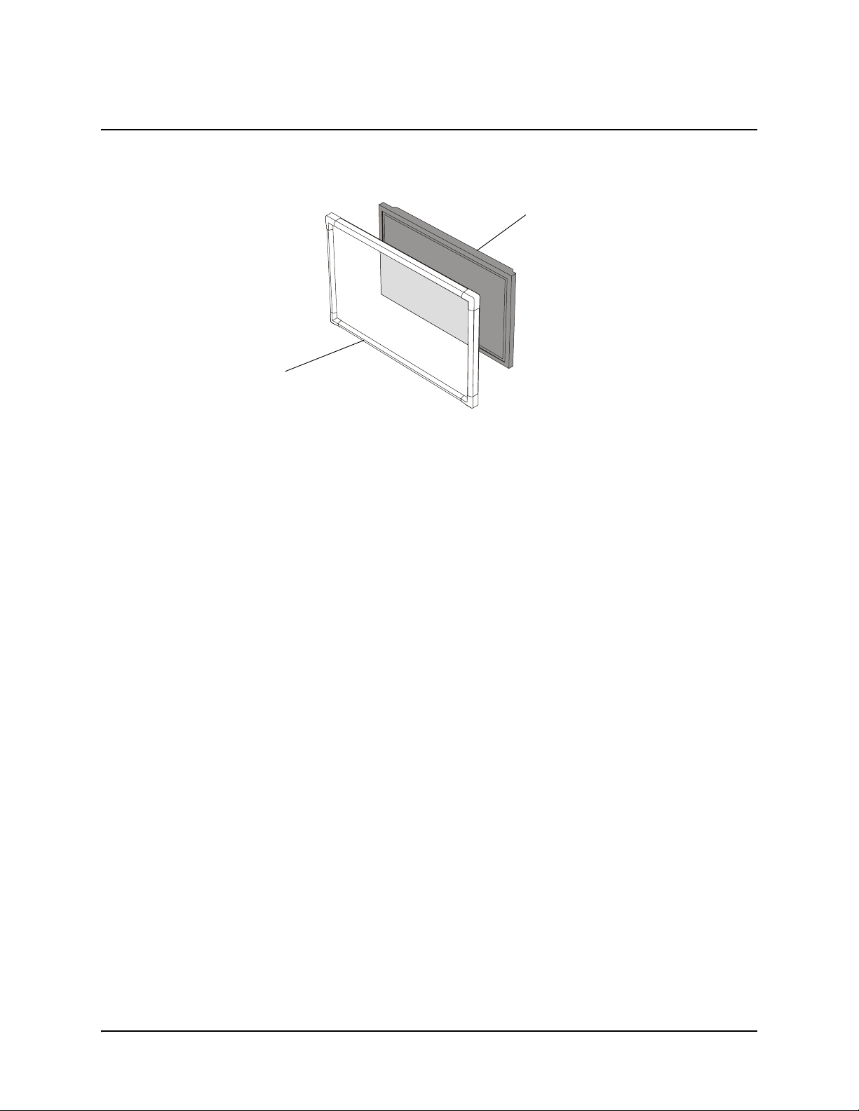
The Actalyst interactive overlay adds touch-screen control to your flat-panel display.
Interactive
Overlay
The Actalyst interactive overlay is specifically designed to work in a digital signage setup. It comes
with a controller and Actalyst software.
Interactive Overlay Technology
Flat-Panel Display
When you’ve installed the interactive overlay, you can view the flat-panel display’s image through
the interactive overlay, and you can control on-screen interactive content by touching the overlay.
The interactive overlay includes DViT™ (Digital Vision Touch) technology, which uses digital
cameras to track objects that interact with the overlay. Each camera is calibrated to recognize the
position of your finger on the interactive overlay.
About This Guide
This guide includes an introduction (this page), software installation instructions (), hardware
installation instructions (page 5) and a user’s guide (page 21).
99-00680-00 B0 Introduction 1
Page 10
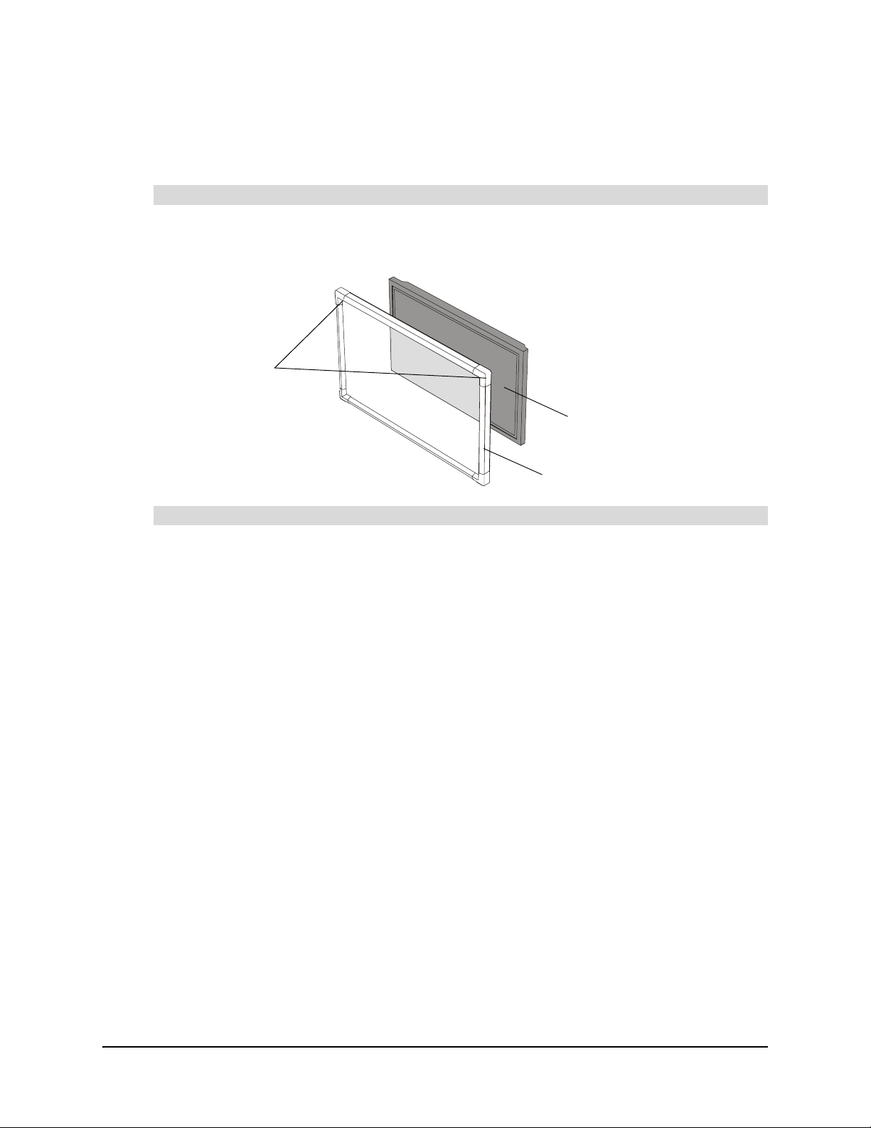
Components of the Actalyst Interactive Overlay
The Actalyst interactive overlay is designed for a digital signage setup. It includes an overlay and
Actalyst software.
The Overlay
The overlay includes embedded digital cameras in the top-left and top-right corners and mounts
onto your flat-panel display.
Cameras
Flat-Panel
Display
Overlay
Actalyst Software
The Actalyst interactive overlay comes with Actalyst software, enabling touch control.
2 Introduction 99-00680-00 B0
Page 11

Installing Actalyst Software
CAUTION
For the Actalyst interactive overlay to function properly, you must run Actalyst software on a
connected computer. You can download the latest version of this software from
http://www.smarttech.com/support/software/index.asp.
NOTE: Use your Actalyst interactive overlay with Actalyst software. Don’t download and install
SMART Board™ software on a computer connected to an Actalyst interactive overlay.
Install Actalyst software before you connect the SMART USB adapter cable to the
computer.
If you connect the cable to the computer by accident, the Found New Hardware
wizard appears. Click the Cancel button in the wizard, and unplug the SMART
USB adapter cable from the computer. Then, install Actalyst software before you
reconnect the cable.
To install Actalyst software
1. Close all open applications on the computer.
2. Insert the Actalyst software CD into your CD drive. The installation program starts
automatically. Follow the on-screen instructions.
If the installation program doesn’t start automatically:
– for the Windows® operating system, select Start > Run and enter x:\autorun.exe
(where x: is your CD drive)
– for Macintosh computers, click the SMART Installer icon to open your CD drive and
double-click the software application file
99-00680-00 B0 Installing Actalyst Software 3
Page 12

4 Installing Actalyst Software 99-00680-00 B0
Page 13
Installing an Actalyst Interactive Overlay
To install your Actalyst interactive overlay, you must:
1. mount the overlay on the flat-panel display (this page)
2. attach the controller (page 14)
3. complete the installation (page 16)
CAUTION
Before you mount the flat-panel display and the Actalyst interactive overlay
onto a stand or wall mount, make sure that the combined weight doesn’t
exceed the maximum weight specified by the manufacturer of the stand or wall
mount.
To calculate the combined weight, add the flat-panel display’s weight (this
should be stated in the user’s guide for the flat-panel display) to the overlay’s
weight (this is stated in the Support section of www.smarttech.com on the
product-specific Specifications page).
Also, if you are mounting a flat-panel display and the overlay onto a wall,
ensure that the wall is strong enough to support the combined weight.
To mount the overlay on a flat-panel display
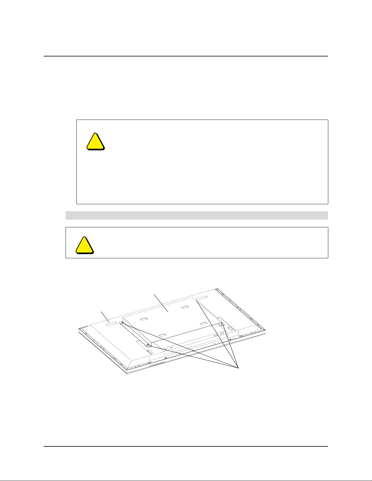
CAUTION
You’ll need assistance with several of the steps in this procedure. Both the flatpanel display and the overlay are heavy.
1. With the assistance of another person, carefully remove the flat-panel display from the wall
mount or the stand, and place it facedown on a flat surface.
Adapter Plate
Flat-Panel Display
Adapter Plate Bolts
NOTE: The appearance of your flat-panel display and its adapter plate can vary from the
diagrams shown in this section. In addition, the number of bolts attaching the adapter plate to
your flat-panel display can be four, six or eight. The figures in this section show four adapter
plate bolts but the same steps are required regardless of the number of bolts.
2. Remove the bolts that attach the adapter plate to the back of the flat-panel display. Put the
bolts in a safe place, as you’ll use them later to reattach the adapter plate.
99-00680-00 B0 Installing an Actalyst Interactive Overlay 5
Page 14
NOTE: The bolt type varies between different flat-panel displays. You may have received an
appropriate tool for removing these bolts with your flat-panel display.
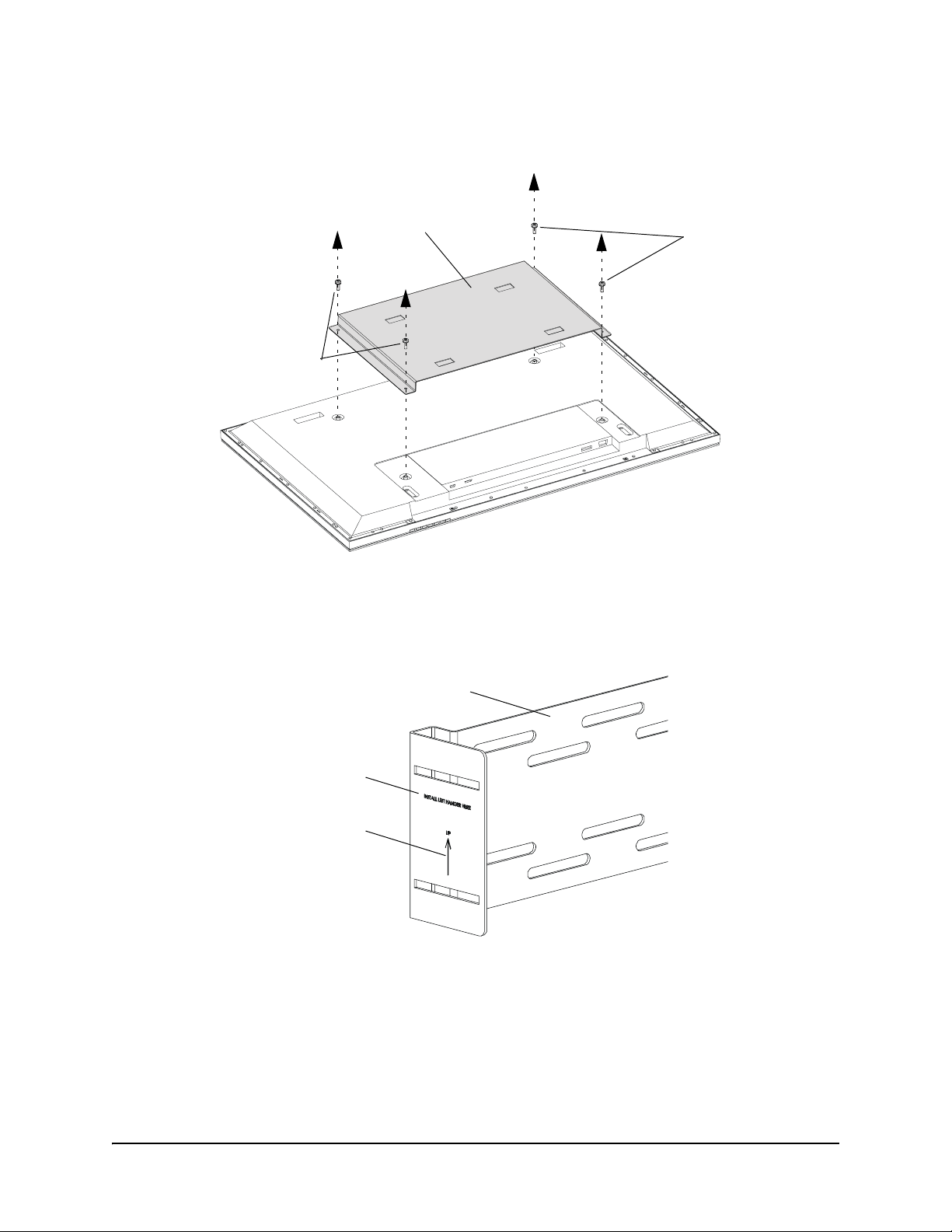
3. Remove the adapter plate.
Adapter Plate
Adapter Plate
Bolts
Adapter Plate
Bolts
NOTE: Take a moment to look at the text and the arrows on the mounting bracket’s center
section.
4. Place the mounting bracket’s center section on a flat surface with the arrows pointing upwards
and the text “Install Left Hanger Here” on your left.
Text
Up Arrow
Mounting Bracket
Center Section
6 Installing an Actalyst Interactive Overlay 99-00680-00 B0
Page 15

5. Attach the left hanger bracket to the left side of the mounting bracket’s center section using
T-handles and carriage bolts. Make sure the U-shaped slot opens at the top of the bracket.
Hanger bracket
T-handle
T-handle
U-shaped slot
Carriage bolt
Carriage bolt
6. Attach the second hanger bracket in the same way.
7. Place the mounting bracket over the flat-panel display with the left hanger bracket on your
right side. The left bracket goes on your right because you are looking at the back of the
flat-panel display. The hanger brackets should face towards the flat surface so that the
horizontal section of each bracket makes a U-shape, as shown in the figure below.
Mounting Bracket
Center Section
Left hanger bracket
is on the right side
(when viewed
from the back)
Both hanger brackets
make a U-shape
CAUTION
If the mounting bracket is mistakenly installed upside-down, the hanger
brackets won’t be able to support an overlay and the installation will be unsafe.
99-00680-00 B0 Installing an Actalyst Interactive Overlay 7
Page 16

8. Using the supplied Installation Template as a guide, align the slotted holes in the mounting
bracket with the adapter plate bolt holes in the flat-panel display.
Do not pass this line
Position Universal Bracket
between lines and
1
Installation Template
AB
IMPORTANT
PX350 Installation Template
Align the top right corner of this temp late with th e face down
plasma panel as shown below.
1
Align the top of the universal bracket with line A.
2
Ensure the bracket is centred left to right on the plasma panel.
33
Slide the universal bracket up the plasma panel, looking
through the slotted holes for the top mounting points on the
back of the plasma panel. Do not pass line B.
4
Finish installing the PX350 as per your instruction manual.
Note:
If your plasma panel has 8 mounting holes, 2 mounting
options may exist. Use the option which does not obscure
adjacent mounting holes.
© 1997-2005 SMART Technologies Inc. All rights reserved. Expression and the SMART logo are trademarks of SMART Technologies Inc. 99-00617-00-A0
Obtain the best possible alignment before mounting either the flat-panel
display or the overlay. After you mount the overlay, you’ll be limited in how
much you can move it relative to the flat-panel display. If the overlay is aligned
poorly, it obscures some of the flat-panel display’s screen.
CAUTION
Try not to position the mounting bracket over the flat-panel display’s cooling
vents. Blocking these vents could cause overheating and damage to the
flat-panel display.
9. Add a supplied washer to each of the exposed adapter plate bolt holes. Don’t add washers to
the two holes covered by the mounting bracket. The washers compensate for the mounting
bracket’s thickness.
Washers
Adapter plate
bolt holes
8 Installing an Actalyst Interactive Overlay 99-00680-00 B0
Page 17

10. Attach the adapter plate over the mounting bracket and the washers using the bolts you
removed in step 2.
Adapter Plate
Mounting Bracket
NOTE: The bolt type varies between different flat-panel displays. You may have received an
appropriate tool for attaching these bolts with your flat-panel display.
11. Loosen the T-handles on the hanger brackets. Push the brackets towards the flat surface and
then tighten the T-handles.
T-handles
Hanger Bracket
12. With the assistance of another person, mount the flat-panel display onto a wall mount or onto
a stand.
CAUTION
Don’t lift the flat-panel display by the mounting bracket.
99-00680-00 B0 Installing an Actalyst Interactive Overlay 9
Page 18

Wall Mount
NOTE: Your wall mount
may appear different from
the one illustrated.
Flat-Panel Display
13. If your flat-panel display has removable handles, remove them to make the overlay’s
installation easier.
14. If there is anything protruding from the front of the flat-panel display that could potentially
scratch the overlay when it’s mounted (for example, a manufacturer’s name or logo) consider
covering it with one of the provided spacing pads.
15. Place the overlay facedown on a flat surface.
IMPORTANT
In the next step, you’ll attach two adjustment handles to the overlay. However,
take a moment to familiarize yourself with how to tighten and loosen these
handles before you attach them.
10 Installing an Actalyst Interactive Overlay 99-00680-00 B0
Page 19

16. Attach a washer and an adjustment handle to the overlay’s two mounting plates, leaving
approximately 1/4" (0.6 cm) of space between the washer and the mounting plate.
Adjustment
Handle
Washer
Mounting Plate
17. With the assistance of another person, mount the overlay onto the flat-panel display by sliding
the adjustment handles into the U-shaped slots in the hanger brackets.
Flat-Panel Display
Hanger Bracket
Overlay
99-00680-00 B0 Installing an Actalyst Interactive Overlay 11
Page 20

NOTE: The adjustment handle and the washer must slide behind the hanger brackets. Ensure
the handles are aligned with the hanger brackets’ U-shaped slots, and temporarily tighten the
handles.
NOTE: For clarity, the T-handle
and the hanger bracket are
shown without the overlay, flatpanel display or the other parts
of the bracket
The washer and
the handle must be
on the same side
of the bracket
Hanger Bracket
CAUTION
Handle
Washer
The handle
slides into the
hanger bracket’s
U-shaped slot
Take care when mounting and then positioning the overlay. The rear of the
overlay can be scratched if it’s held tight to the flat-panel display and then
moved in any direction.
18. With the assistance of another person, and while supporting the overlay, loosen both
adjustment handles, vertically adjust the overlay so that you can see most of the flat-panel
display’s screen, and then tighten the handles. You will vertically adjust the overlay more
accurately in step 20.
Overlay
Adjustment
Handle
Flat-Panel Display
12 Installing an Actalyst Interactive Overlay 99-00680-00 B0
Page 21

19. With the assistance of another person, and while supporting the overlay, loosen the T-handles
on the hanger brackets, carefully slide the overlay toward the flat-panel display so that the
glass rests against the flat-panel display, and then tighten the T-handles.
Overlay
T-handles
Hanger Bracket
Flat-Panel Display
CAUTION
You could damage the hanger bracket if you push the overlay forward with too
much force. Support the back of the hanger bracket when you slide the overlay
towards it. If this is not possible, slide the overlay as carefully as you can.
20. With the assistance of another person, and while supporting the overlay, loosen both
adjustment handles, vertically adjust the overlay so that you can see all of the flat-panel
display’s screen, and then tighten the handles.
Overlay
Adjustment
Handle
Flat-Panel Display
TIP
If you ever uninstall the overlay, position the adjustment handles so they’re facing
directly upwards as you lift the overlay out of the hanger brackets. This prevents
the handles from catching on the hanger bracket or the T-handles as you move the
overlay.
99-00680-00 B0 Installing an Actalyst Interactive Overlay 13
Page 22

To attach the controller
CAUTION
Install Actalyst software before you connect the overlay to the computer.
For more information, see page 3.
NOTE: Depending upon where and how the overlay is mounted, you may need to perform some of
the following steps by touch due to reduced visibility.
1. Remove the two thumbscrews in the bottom center of the back of the overlay. Place the
thumbscrews somewhere safe and accessible as you will need these thumbscrews in step 3.
Thumbscrews
NOTE: Don’t remove any thumbscrews that you attached to the mounting bracket earlier in
the installation.
2. Slide the holes in the controller over the threaded posts on the overlay.
Controller
Threaded
Posts
3. Attach the thumbscrews that you removed in step 1 to the threaded posts. These
thumbscrews hold the controller to the overlay.
Thumbscrews
14 Installing an Actalyst Interactive Overlay 99-00680-00 B0
Page 23

4. Connect the MOD8 cable to the controller.
MOD8 Cable
Controller
5. Connect the DB9 end of the SMART USB adapter cable to the controller. You’ll connect the
other end of this cable to your computer when you complete the installation.
DB9 Connector
OR
If you ordered a straight-through DB9-to-DB9 serial cable with your interactive overlay,
connect one end to the controller. You’ll connect the other end of this cable to your computer
when you complete the installation.
NOTE: You can order a straight-through DB9-to-DB9 serial cable from SMART Technologies.
To do this, contact Technical Support (page 35).
OR
If you ordered the WC2 Wireless Serial Adapter with your interactive overlay, connect one
radio to the controller. You’ll connect the second radio to your computer later.
99-00680-00 B0 Installing an Actalyst Interactive Overlay 15
Page 24

To complete the installation
1. Connect the MOD8 cable to the corresponding port on the back of the overlay. You connected
the other end of this cable to the controller earlier.
MOD8 Port
MOD8 Cable
2. Connect the power supply connector to the overlay’s power port.
Power Port
Power Connector
Power Supply
16 Installing an Actalyst Interactive Overlay 99-00680-00 B0
Page 25

3. Connect the power cable to both the power supply and a wall outlet.
Power Supply
NOTE: Your power cable
Power Cable
might look different because
your overlay comes with a
power cable that works with
your country’s power outlets
4. Connect the SMART USB adapter cable to a USB port on your computer. Earlier, you
connected this cable to the controller.
OR
If you ordered a straight-through DB9-to-DB9 serial cable with your interactive overlay,
connect it to an available serial port on your computer. Earlier, you connected this cable to the
controller.
OR
If you’re using the WC2 Wireless Serial Adapter, connect the second radio to your computer
by following the instructions that came with the kit.
99-00680-00 B0 Installing an Actalyst Interactive Overlay 17
Page 26

18 Installing an Actalyst Interactive Overlay 99-00680-00 B0
Page 27

Preparing the Interactive Overlay for Use
The previous chapters showed you how to install Actalyst software (page 3), and install your
interactive overlay and connect it to the computer (page 16). However, the overlay still isn’t quite
ready to use. This chapter shows you how to:
• open the SMART Board Control Panel (this page)
• orient the interactive overlay (this page)
• configure the COM port in the software (page 20), if you’re using the optional DB9-to-DB9
serial cable to connect the interactive overlay to a serial port on your computer
Opening the SMART Board Control Panel
Open the SMART Board Control Panel to access the settings for Actalyst software.
To open the SMART Board Control Panel (Windows operating system)
1. Open the Windows Control Panel.
2. Double-press SMART Board.
To open the SMART Board Control Panel (Macintosh computers)
1. Open the Finder.
2. Select the Go > Applications menu option.
3. Press SMART Board Software.
4. Double-press Control Panel.
Orienting the Interactive Overlay
Orient the interactive overlay to ensure that the computer accurately tracks your contact with the
screen. The default orientation level is a Standard (9-point) orientation. Although Actalyst software
assigns a default orientation that’s normally adequate, if you find this level isn’t precise enough,
use the Fine (20-point) orientation level to ensure the greatest possible level of accuracy. You can
also use the Quick (4-point) orientation level.
To orient the interactive overlay
1. Open the SMART Board Control Panel (see above).
2. For Windows operating systems, press Align/Orient the SMART Board.
For Macintosh computers, press Orient.
3. Follow the on-screen instructions, pressing your finger squarely on the center of each cross.
NOTE: If you press on the crosses out of sequence or inaccurately, a Bad Orientation Point
dialog box appears. Use the mouse to click OK, because touch sensitivity isn’t available.
4. Test the orientation by moving your finger across the interactive overlay. The pointer should
track your finger very closely and appear directly beneath the center of your fingertip.
99-00680-00 B0 Preparing the Interactive Overlay for Use 19
Page 28

NOTE: If the pointer doesn’t accurately track your finger, calibrate the digital cameras
(page 23).
To change the orientation level
1. Open the SMART Board Control Panel (page 19).
2. For Windows operating systems, press SMART Board Settings, and then press Alignment/
Orientation Precision from the list.
For Macintosh computers, press Advanced, and then press Orientation Precision.
3. Press Quick (4 points), Standard (9 points) or Fine (20 points), and then press OK.
NOTE: This setting will remain in effect for all subsequent orientations until you perform steps
1–3 again and restore the default (Standard) orientation or otherwise change the orientation
level.
Configuring the COM Port for a Serial Connection
If you connect the interactive overlay to a serial port on your computer using the optional
DB9-to-DB9 serial cable, you must select the serial (COM) port in Actalyst software.
NOTE: If you’ve connected the standard SMART USB adapter cable to a USB port on your
computer, disregard the procedure that follows.
To configure a COM port (Windows operating systems)
1. Open the SMART Board Control Panel (page 19).
2. Press SMART Board Settings.
The SMART Board Settings dialog box appears.
3. Press the Add SMART Board arrow button, and then press Manually choose COM port.
The Select COM Port dialog box appears.
4. If you know which port you connected the interactive overlay to, select it from the list and press
Select.
OR
If you’re unsure of the correct port, click the Detect SMART Hardware button. Actalyst
software locates the correct port for the attached interactive overlay.
To configure a COM port (Macintosh computers)
1. Open the SMART Board Control Panel (page 19).
2. Press Connect.
The Select Port dialog box appears.
3. If you know which port you connected the interactive overlay to, select it from the list and press
Connect.
OR
If you’re unsure of the correct port, press the Detect SMART Hardware button. Actalyst
software locates the correct port for the attached interactive overlay.
20 Preparing the Interactive Overlay for Use 99-00680-00 B0
Page 29

Using Actalyst Software
IMPORTANT
Don’t download and install SMART Board software onto a computer connected to
an Actalyst interactive overlay.
Components of Actalyst Software
Actalyst software includes many tools that will help you get the most out of your interactive overlay.
This software includes:
• SMART Board Control Panel, to change the software and hardware settings
• SMART Board Diagnostics, a troubleshooting application
NOTE: If you’re using the Windows XP operating system with Service Pack 2 installed, you must
change a setting on Internet Explorer to access the Help Center topics. Press Tools > Internet
Options, and press the Advanced button. Under Security, select the Allow active content to
run in files from my computer check box. To access the Help Center, press any of the Help
buttons in the software.
Controlling the Computer
Think of the interactive overlay as an extension of your computer. Press the screen to click as you
would with a mouse. Anything that you can do by left-clicking on your computer screen, you can do
by pressing at the interactive overlay.
Clicking
To left-click, press on the interactive overlay (as you normally would with a mouse).
To double-click, press twice. For example, to open a program, press twice on its desktop icon.
To right-click, press and hold your finger on the interactive overlay. In approximately three
seconds, the right-click menu for the desktop or the active application appears.
Tips for Pressing
Press firmly on the interactive overlay.
Don’t lean your palm, arm or anything else against the interactive overlay. More than one point of
contact with the interactive screen can confuse the product’s electronics. It will select only the
initial point of contact.
99-00680-00 B0 Using Actalyst Software 21
Page 30

Customizing Actalyst Software
You can customize Actalyst software by changing the settings in the SMART Board Control Panel.
These procedures are detailed in the Help Center, which you can access by opening the SMART
Board Control Panel (page 19) and pressing the Help button. Any changes that you make to the
software are saved with your logon ID for the computer, so your settings will load the next time you
log on.
Further Information
You should also check www.smarttech.com for more resources. At this site, you’ll find information
on each product, including specifications. The Training Center of this website has learning
resources, free hands-on lessons and information on how to get more training. You’ll find up-todate, product-specific information in the Support area of this website, including frequently asked
questions (FAQs), technical bulletins and resource centers.
22 Using Actalyst Software 99-00680-00 B0
Page 31

Cleaning and Troubleshooting
Cleaning
Turn off your computer before you clean the interactive overlay. If you touch the interactive overlay
when the computer is in any other state (for example, with a program open or at the desktop), you
may activate program components or scramble desktop icons.
Clean the interactive overlay surface regularly so that dust buildup doesn’t adversely affect the
operation of the interactive overlay.
Don’t spray glass cleaner directly onto the overlay. Instead, spray it lightly on a cloth and then
gently wipe the overlay.
Troubleshooting
If you look at the back of the interactive overlay, you’ll see two LEDs. One LED glows red to
indicate that the interactive overlay is receiving power. The second LED glows green when the
corner cameras and the master controller are communicating properly. If you encounter a problem
with the interactive overlay, check all the cable connections. If this doesn’t solve the problem, note
the LED’s color and contact Technical Support (page 35).
Calibrating the Cameras
Digital cameras in the interactive overlay’s top corners track your finger. If the cameras become
misaligned for any reason, an area of the screen may be unresponsive to touch.
Fortunately, you can easily fix this problem by performing a simple calibration procedure. If you
think that you need to calibrate the cameras, contact SMART Technical Support (page 35).
99-00680-00 B0 Cleaning and Troubleshooting 23
Page 32

24 Cleaning and Troubleshooting 99-00680-00 B0
Page 33

Appendix A: Removing and Installing the Frame
If you ordered a frame with your Actalyst interactive overlay, the frame is already installed when
you receive it. The following paragraphs explain how you can remove and replace the frame.
NOTE: Although many of the figures in this appendix show the frame and the Actalyst interactive
overlay in portrait mode, the following information is valid for both portrait and landscape modes.
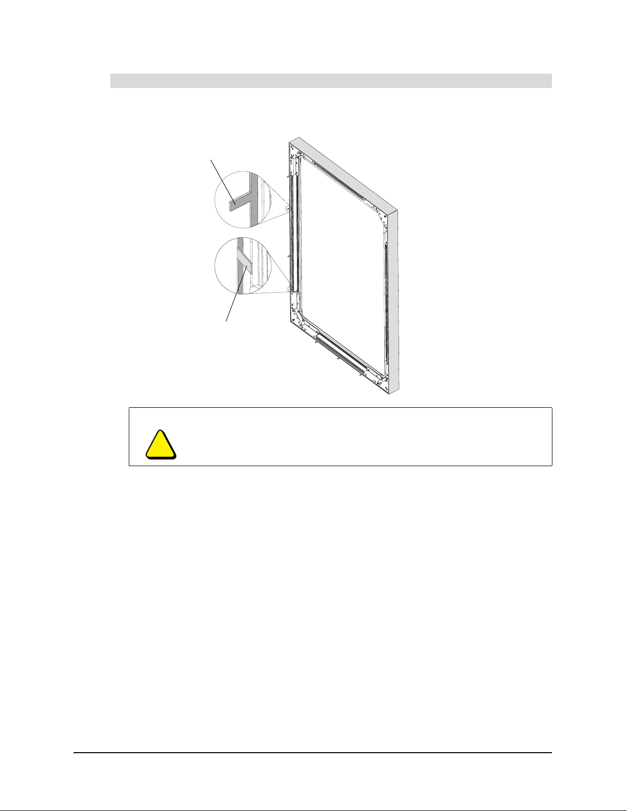
Removing the Frame
The frame is attached to the Actalyst interactive overlay by 14 tabs. You need to bend these tabs
with a screwdriver before you can separate the frame from the overlay.
When all 14 tabs point away
from the overlay, you can
remove the frame
When the tabs are bent inwards,
the frame is securely mounted to
the overlay
NOTE: For clarity, the
Actalyst interactive
overlay is shown without
the flat-panel display and
its wall mount or stand
Actalyst
Interactive
Overlay
Frame
The method for removing the frame varies depending on whether you have access to the frame’s
tabs when the Actalyst interactive overlay is mounted:
• If you have access to the tabs when the overlay is mounted, complete the procedure on
page 26.
• If you don’t have access to the tabs when the overlay is mounted (for example, if the back of
the overlay is against a wall) complete the procedure on page 27.
99-00680-00 B0 Appendix A: Removing and Installing the Frame 25
Page 34
To remove the frame (from a mounted Actalyst interactive overlay)
1. Using a flathead screwdriver, bend each of the tabs so that they point directly away from the
Actalyst interactive overlay.
Bend each tab until it
points directly away
from the overlay
The tabs are initially
bent inwards
CAUTION
Bend the tabs only so far as to ensure that they won’t scratch the overlay as
you lift the frame away from the overlay. If you bend the tabs beyond this point,
you can cause them unnecessary wear and tear.
NOTE: For clarity, the
Actalyst interactive
overlay is shown without
the flat-panel display and
its wall mount or stand
NOTE: If you don’t have enough access to the tabs to bend them, you’ll have to uninstall the
overlay (page 27).
26 Appendix A: Removing and Installing the Frame 99-00680-00 B0
Page 35

2. Lift the frame away from the overlay.
Actalyst
Interactive
Overlay
NOTE: For clarity, the
Actalyst interactive
overlay is shown without
the flat-panel display and
its wall mount or stand
Frame
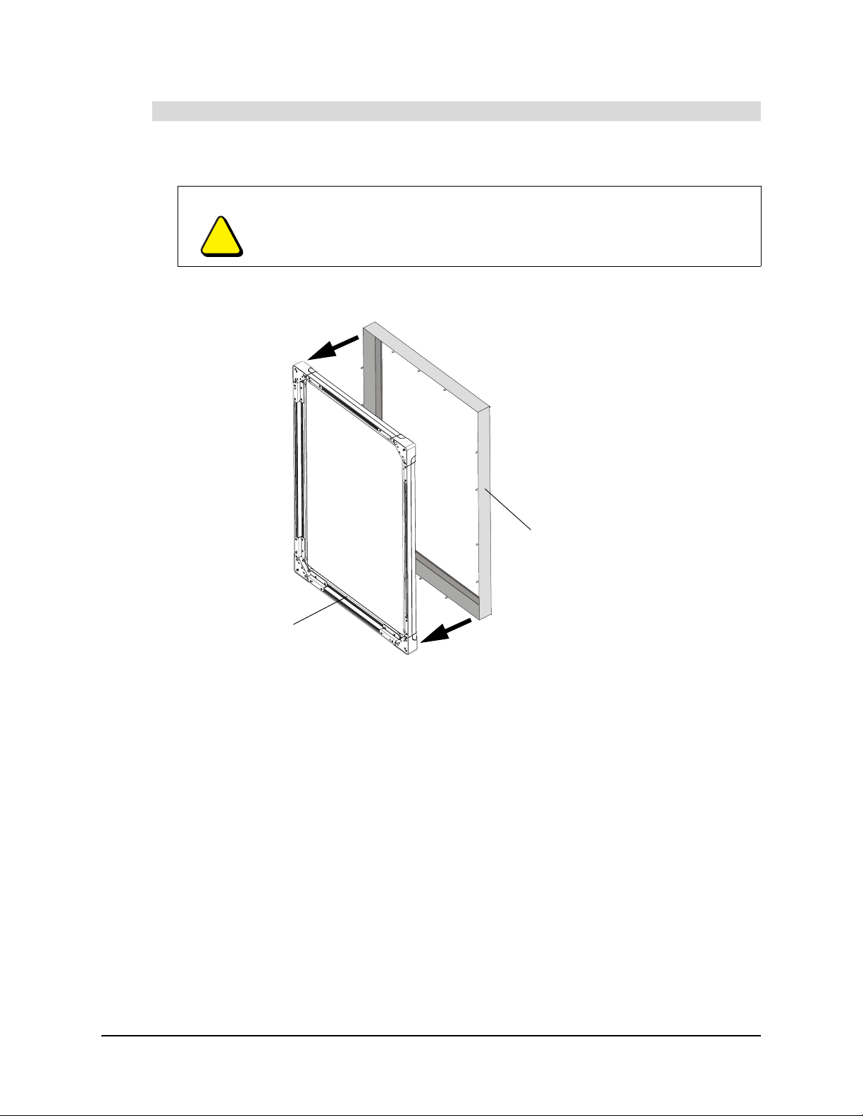
To remove the frame (from an unmounted Actalyst interactive overlay)
1. Remove the Actalyst interactive overlay and its frame from the flat-panel display. Place the
overlay and the frame facedown on a flat surface.
Actalyst
Interactive
Overlay
Frame
99-00680-00 B0 Appendix A: Removing and Installing the Frame 27
Page 36

2. Using a flathead screwdriver, bend each tab so that they point up.
The tabs are initially
bent inwards
Bend each tab until it
points directly up
CAUTION
Bend the tabs only so far as to ensure that they won’t scratch the overlay as
you lift it out of the frame. If you bend the tabs beyond this point, you can cause
them unnecessary wear and tear.
3. Lift the overlay out of the frame.
Actalyst
Interactive
Overlay
Installing the Frame
Frame
The installation procedure varies depending on whether you have access to the frame’s tabs when
it’s mounted:
• If you have access to the tabs when the overlay is mounted, complete the procedure on
page 29.
• If you don’t have access to the tabs when the overlay is mounted (for example, if the back of
the overlay is against a wall) complete the procedure on page 30.
28 Appendix A: Removing and Installing the Frame 99-00680-00 B0
Page 37
To install the frame with the Actalyst interactive overlay already mounted
1. Check that none of the frame’s tabs bend inwards. If they do, they could scratch the overlay as
you mount the frame onto the overlay.
CAUTION
Bend the tabs only so far as to ensure that they won’t scratch the overlay as
you mount the frame onto the overlay. If you bend the tabs beyond this point,
you can cause them unnecessary wear and tear.
2. Lift the frame onto the Actalyst interactive overlay.
NOTE: For clarity, the
Actalyst interactive
overlay is shown without
the flat-panel display and
its wall mount or stand
Frame
Actalyst
Interactive
Overlay
99-00680-00 B0 Appendix A: Removing and Installing the Frame 29
Page 38

3. Using the handle of a screwdriver, or a similar instrument, bend all of the tabs inwards.
The tabs are initially
pointing away from
the overlay
Bend each tab inwards
NOTE: For clarity, the
Actalyst interactive
overlay is shown without
the flat-panel display and
its wall mount or stand
NOTE: Bend the tabs as far as they’ll go to ensure a tight fit for the frame.
CAUTION
Don’t use a hammer to bend the tabs, as it can deform the tabs and could
damage the overlay.
NOTE: If you don’t have enough access to the tabs to bend them, you’ll have to uninstall the
overlay (see below).
To install the frame and remount the Actalyst interactive overlay
1. Place the frame on a flat surface with the tabs facing directly upwards.
Frame
30 Appendix A: Removing and Installing the Frame 99-00680-00 B0
Page 39

2. Check that none of the frame’s tabs bend inwards. If they do, they could scratch the overlay as
you place the overlay into the frame.
CAUTION
Bend the tabs only so far as to ensure that they won’t scratch the overlay as
you place the overlay into the frame. If you bend the tabs beyond this point,
you can cause them unnecessary wear and tear.
3. If you have not done so already, uninstall the Actalyst interactive overlay.
4. Place the overlay into the frame.
Actalyst
Interactive
Overlay
Frame
5. Using the handle of a screwdriver, or a similar instrument, bend all of the tabs inwards.
Bend each tab
inwards
The tabs are initially
pointing away from the
overlay
NOTE: Bend the tabs as far as they’ll go to ensure a tight fit for the frame.
CAUTION
Don’t use a hammer to bend the tabs, as it can deform the tabs and could
damage the overlay.
6. Mount the overlay onto the flat-panel display. For further information, see page 5.
99-00680-00 B0 Appendix A: Removing and Installing the Frame 31
Page 40

32 Appendix A: Removing and Installing the Frame 99-00680-00 B0
Page 41

Waste Electrical and Electronic Equipment (WEEE) Regulations
Waste Electrical and Electronic Equipment (WEEE) regulations apply to all electrical and
electronic equipment sold within the European Union.
When you dispose of any electrical or electronic equipment, including SMART products, we
strongly encourage you to contact your local WEEE recycling agency for recycling and disposal
advice.
Your SMART product required the extraction and use of natural resources for its production. It may
contain hazardous substances. By disposing of electrical and electronic equipment appropriately,
you lower the impact of these substances upon health and the environment and reduce the
pressure on natural resources. Recycling agencies can reuse or recycle most of the materials from
your product.
Please think about how you intend to dispose of any product that has a WEEE symbol or
accompanying WEEE guidelines.
If you need more information on the collection, reuse and recycling of electrical and electronic
equipment, please contact your local WEEE recycling agency.
Alternatively, contact your local reseller or SMART Technologies for information on the
environmental performance of our products.
99-00680-00 B0 Waste Electrical and Electronic Equipment (WEEE) Regulations 33
Page 42

34 Waste Electrical and Electronic Equipment (WEEE) Regulations 99-00680-00 B0
Page 43

Customer Support
Online Support
www.smarttech.com/support
Visit the SMART Technologies support site to view and download user’s guides, “how-to” and
troubleshooting articles, software and more.
Training
Visit www.smarttech.com/trainingcenter for free training materials and information about our
training services.
Contacting SMART Technical Support
SMART Technical Support welcomes your call. However, if you experience difficulty with your
SMART product, you may want to contact your local reseller first. Your local reseller may be able
to resolve the issue without delay.
All SMART products include free online, telephone, fax and e-mail support:
Online: www.smarttech.com/contactsupport
Telephone: +1.403.228.5940 or
Toll Free 1.866.518.6791 (Canada/U.S.)
(Monday to Friday, 5 a.m. – 6 p.m. Mountain Time)
Fax: +1.403.806.1256
E-mail: support@smarttech.com
When you phone Technical Support, it will be helpful if you have access to your interactive overlay
during the call. The support representative may ask you for the following information:
• the unit’s serial number
• the version of the software that’s causing the problem and the version of your computer’s
operating system (if applicable)
NOTE: You can locate the serial number under the lower right hand corner.
TIP
Write the Actalyst’s serial number in the front of this guide for future reference.
99-00680-00 B0 Customer Support 35
Page 44

General Inquiries
Address: SMART Technologies
1207 – 11 Ave SW, Suite 300
Calgary, AB T3C 0M5
CANADA
Switchboard: +1.403.245.0333 or
Toll Free 1.888.42.SMART (Canada/U.S.)
Fax: +1.403.228.2500
E-mail: info@smarttech.com
Warranty
Product warranty is governed by the terms and conditions of SMART's “Limited Equipment
Warranty” that shipped with the SMART product at the time of purchase.
Registration
To help us serve you, register online at www.smarttech.com/registration.
Sending Feedback
You can help us improve our technical documentation by e-mailing your comments to
Documentation@smarttech.com.
Obtaining More Information on SMART Products
Visit www.smarttech.com/support to:
• download PDF versions of our user guides, installation instructions and more
• read technical bulletins, FAQs and tips
• troubleshoot a problem
• explore our resource centers to learn about conferencing and room control systems
• download the latest version of Actalyst software
36 Customer Support 99-00680-00 B0
Page 45

Index
A
Actalyst Interactive Overlay
Actalyst Software, 2
Cleaning, 23
Completing the Installation, 16
Components, 2
Digital Vision Touch Technology, 1
Frame, 25
Mounting on a Flat-Panel Display, 5
Orienting, 19
Preparing for use, 19
Technology, 1
Troubleshooting, 23
Actalyst Software
Installing, 3
Using, 21
C
Calibrating the Cameras, 23
Cleaning, 23
Clicking, 21
Completing the Installation, 16
Components of the Interactive Overlay, 2
Configuring a Port, 20
Contacting SMART Technical Support, 35
D
Detect SMART Hardware, 20
Digital Cameras, 1
Digital Vision Touch Technology, 1
Double-Clicking, 21
DViT Technology, 1
Frame, 25
Mounting the Interactive Overlay, 5
Interactive Overlay
see Actalyst Interactive Overlay
M
Mounting the Interactive Overlay, 5
O
Orienting
Fine Orientation, 19
Interactive Overlay, 19
Quick Orientation, 19
P
Preparing the Interactive Overlay for use, 19
Q
Quick Orientation, 19
R
Removing the Frame, 25
Right-Clicking, 21
S
SMART Technical Support, 35
T
Troubleshooting, 23
F
Fine Orientation, 19
Frame
Installing, 25
Removing, 25
I
Installing
Actalyst Software, 3
Completing the Installation, 16
99-00680-00 B0 Index 37
Page 46

SMART Technologies
1207 – 11 Avenue SW, Suite 300
Calgary, AB T3C 0M5
CANADA
www.smarttech.com/support www.smarttech.com/contactsupport
Support +1.403.228.5940 or Toll Free 1.866.518.6791 (Canada/U.S.)
99-00680-00 REV B0
 Loading...