

Page 1
SMARTBoard®
8000i-G4series
Interactive flat panels
Setup and maintenance guide
For models 8070i-G4-SMP and 8084i-G4-SMP
Page 2

Product registration
If you register your SMART product, we’ll notify you of new features and software upgrades.
Register online at smarttech.com/registration.
Keep the following information available in case you need to contact SMARTSupport.
Serial number:
Date of purchase:
FCC warning
This equipment has been tested and found to comply with the lim its for a Class A digital device, pursuant to Part 15 of the FCC R ules. Theselimi ts are designed to provide
reasonable protection against harmful i nterference w henthe equipm entis operatedi n a commercial environment. This equipment generates, uses andcan radiate r adio
frequency energy and, if not installed and used in accordancew ith the m anufacturer’s instructions, may causeharmful interference to radio communications. Operation of
this equipment in a residential areai s likely tocause harm ful i nterference in which case the user will be required to correct the interference at his own expense.
Licenses
Supportedli censes may differ by model.
The terms HDMI andH DMI High-Definition Multimedia Interface, and the HDMI logo are trademarks or registered trademarks of HDM I Licensing LLC i n the United States
and other countries.
ABOUT DIVX VIDEO: D ivX® is a digital video format cr eated by DivX, LLC, a subsidiary of R ovi C orpor ation. This is an official DivXCertified® devicethat plays DivX
video. Visit divx.com for more informationand software tools to convert your files into D ivX videos.
ABOUT DIVX VIDEO-ON-DEMAND: This DivX Certified® device must beregistered in order to play purchased Di vX Video-on-Demand (VOD) movies. T o obtain your
registration code, locate the DivX VOD sectioni n your device setup m enu. Go to vod.divx.com for m ore inform ationon how to completeyour registration.
DivX Certified® to play DivX® video upto HD 1080p,including premium content.
DivX®, DivX C ertified® and associated logos are trademarks of Rovi Corporation or its subsidiaries andare used under l icense.
Coveredby one or m ore of the foll owing U.S. patents: 7,295,673; 7,460688; 7,515710; 7,519,274
Manufacturedunder license from DolbyLaboratories. Dolby andthe double-D symbol are tradem arks of DolbyLaboratories.
Trademark no tice
SMARTBoard, SMARTInk, SMARTM eetingPro, SMARTNotebook, DViT, SMARTGoWi re, SMARTRoomSystem , sm arttech, the SMART l ogoand all SMART
taglines are trademarks or registeredtrademarks of SMARTTechnologiesULC in the U.S. and/or other countries. Microsoft, Windows and Lync are either registered
trademarks or trademarks of Micr osoftCorporation i n the U.S. and/or other countri es. Molex is a trademark of Molex, its affil iates, related companies, licensors, and/or j oint
venture partners.All third-party product andcompany names may be trademarks of their respective owners.
Copyright notice
© 2013–2014SMARTTechnologiesULC. All rights reserved. No part of this publicationmay be repr oduced, transmitted, transcribed, stored in a retrieval system or
translated into any l anguage in any form by any means without the prior w ritten consent of SMARTTechnologiesULC. Informationi n this manual is subject tochange
without notice and does not r epresent a commitment on the part of SMART.
This pr oduct and/or use thereof covered by one or more of the following U.S. patents.
www.smarttech.com/patents.
01/2014
smarttech.com/kb/170446
Page 3

Important information
W A R N I N G
l Failure to follow the installation instructions shipped with your SMART product could result in
personal injury and product damage which may not be covered by your warranty.
l Do not open or disassemble the SMART product. You risk electrical shock from the high
voltage inside the casing. Opening the casing also voids your warranty.
l Do not stand (or allow children to stand) on a chair to touch the surface of your SMART
product. Rather, mount the product at the appropriate height.
l To reduce the risk of fire or electric shock, do not expose the SMART product to rain or
moisture.
l If your SMART product requires replacement parts, make sure the service technician uses
replacement parts specified by SMARTTechnologies or parts with the same characteristics
as the original.
l Ensure that any cables extending across the floor to your SMART product are properly
bundled and marked to avoid a trip hazard.
l Do not insert objects inside the cabinet ventilation holes, because they could touch dangerous
voltage points and cause electric shock, fire or product damage which may not be covered by
your warranty.
l Do not place any heavy objects on the power cable. Damage to the cable could cause shock,
fire or product damage which may not be covered by your warranty.
l Useonly extension cords and outlets into which this product’s polarized plug can be fully
inserted.
l Use the power cable provided with this product. If a power cable is not supplied with this
product, please contact your supplier. Use only power cables that match the AC voltage of the
power outlet and that comply with your country’s safety standards.
l If the glass is broken, do not touch the liquid crystal. To prevent injury, handle glass fragments
with care when disposing of them.
l Do not move or mount the interactive flat panel by connecting rope or wire to its handles.
Because the interactive flat panel is heavy, rope, wire or handle failure could lead to personal
injury.
i smarttech.com/kb/170446
Page 4

I M P O R T A N T I N F O R M A T I O N
l To prevent personal injury, do not attempt to mount or carry the interactive flat panel using your
own strength. Instead, use a lifting device with the included attachable eyebolts. The eyebolts
are not post-installation hardware.
l Use only VESA®-approved mounting hardware.
l Disconnect all power cables for your interactive flat panel from the wall outlet and seek
assistance from qualified service personnel when any of the following occurs:
o
The power cable or plug is damaged
o
Liquid is spilled into the interactive flat panel
o
Objects fall into the interactive flat panel
o
The interactive flat panel is dropped
o
Structural damage such as cracking occurs
o
The interactive flat panel behaves unexpectedly when you follow operating instructions
C A U T I O N
l Do not install or remove the I/O extension module or an OPS computer while the interactive
flat panel is turned on.
l Before you clean your SMART product, shut down or disconnect the computer. Otherwise,
you may scramble the desktop icons or inadvertently activate applications when you wipe the
screen.
l Avoid setting up and using the SMART product in an area with excessive levels of dust,
humidity and smoke.
l Make sure an electrical socket is near your SMART product and remains easily accessible
during use.
l The external power supply needs to meet the Limited Power Source (LPS) requirements of
CSA/UL/IEC/EN 60950-1, when required.
l This SMART product should be used only with European TN and TT power distribution
systems.
It is not suitable for older, IT-type power distribution systems found in some European
countries. "This system (IT-type) is widely used isolated from earth, in some installations in
France, with impedance to earth, at 230/400V, and in Norway, with voltage limiter, neutral not
distributed, at 230V line-to-line." (IEC 60950:1999)
Contact qualified personnel if you’re uncertain of the type of power system available where
you’re installing your SMART product.
ii smarttech.com/kb/170446
Page 5
I M P O R T A N T I N F O R M A T I O N
l You must connect the USB cable that came with your SMARTBoard® interactive flat panel to
a computer that has a USB compliant interface and that bears the USB logo. In addition, the
USB source computer must be compliant with CSA/UL/EN 60950 and bear the CE mark and
CSA and/or UL Mark(s) for CSA/UL 60950. This is for operating safety and to avoid damage to
the SMARTBoard interactive flat panel.
I M P O R T A N T
l The following are the power requirements for your interactive flat panel:
Model Power requirements
8070i-G4-SMP 100–240V, 8.9–4.5A, 50/60Hz, 310W
8084i-G4-SMP 100–240V, 50/60Hz, 530W
l For additional requirements and other information, refer to your interactive flat panel’s
specifications (see Specifications on page 9).
iii smarttech.com/kb/170446
Page 6

Page 7

Contents
Important information i
Chapter 1: Welcome 1
About your interactive flat panel 2
About this guide 9
Other documentation and resources 9
Chapter 2: Mounting your interactive flatpanel 13
Before mounting your interactive flat panel 13
Choosing a location 15
Choosing a height 16
Chapter 3: Connecting power and devices 17
Connector panels 18
Connecting power 21
Connecting the room computer 22
Connecting cables for laptops 22
Connecting external speakers 24
Connecting other devices 24
Disabling the USB receptacles 24
Chapter 4: Setting up your interactive flatpanel and room computer 27
Turning on your interactive flat panel and roomcomputer for the first time 27
Installing SMART software 28
Running the connection wizard 28
Chapter 5: Using your interactive flat panel 31
Turning on and turning off your interactiveflatpanel 31
Using presence detection 33
Using your interactive flat panel with the roomcomputer 34
Using your interactive flat panel with guestlaptops 35
Changing input sources 37
Using the remote control 38
Chapter 6: Maintaining your interactiveflatpanel 45
Opening SMARTSettings 45
Updating software 46
Updating firmware 46
Calibrating your interactive flat panel 47
v smar ttech.com/kb/170446
Page 8

C O N T E N T S
Orienting your interactive flat panel 48
Replacing batteries in the remote control 49
Replacing a pen nib 49
Cleaning the screen 50
Cleaning the presence detection sensors 50
Cleaning the camera windows and reflective tape 51
Maintaining ventilation 51
Preventing condensation 52
Checking the interactive flat panel installation 52
Removing your interactive flat panel 52
Transporting your interactive flat panel 53
Chapter 7: Troubleshooting your interactiveflatpanel 55
Locating the interactive flat panel serial number 55
Resolving image issues 55
Resolving touch control and digital ink issues 60
Resolving audio issues 62
Resolving remote control issues 63
Resolving presence detection issues 64
Resolving issues using the SMART ConnectionWizard 65
Resolving issues using SMARTBoard Diagnostics 66
Appendix A: Using the on-screen display menu 67
Changing settings in the on-screen display menu 67
SMARTBoard8070i-G4-SMP interactiveflatpanel on-screen display menu 68
SMARTBoard8084i-G4-SMP interactiveflatpanel on-screen display menu 74
Appendix B: Remotely managing your interactive flat panel 83
Connecting and configuring a room control system 84
Power modes 85
Room control system programming commands and responses 86
SMARTBoard8070i-G4-SMP interactive flat panel commands 88
SMARTBoard8084i-G4-SMP interactive flat panel commands 97
Appendix C: Hardware environmental compliance 111
Waste Electrical and Electronic Equipment and Battery regulations (WEEE and Battery
Directives) 111
Batteries 111
More information 111
Index 113
vi smar ttech.com/kb/170446
Page 9

Chapter 1
About your interactive flat panel 2
Features 2
Touch-enabled interactivity 2
Gesture support 2
Dual user support 2
Presence detection 2
Audio 3
SMART software 3
Components 4
Screen 4
Cameras and reflective tape channel 5
Presence detection sensors 5
Speakers 6
Pens and eraser 6
Color select module 6
Front control panel 7
Remote control 8
I/O extension module 8
Differences between models 8
About this guide 9
Other documentation and resources 9
Specifications 9
Installation instructions 10
Cabling guides 10
Help 10
Training 11
Knowledge base 11
This chapter introduces you to your SMARTBoard interactive flat panel and this guide.
1 smarttech.com/kb/170446
Page 10

C H A P T E R 1
Welcome
About your interactive flat panel
Your SMARTBoard interactive flat panel features SMART’s proprietary DViT® (DigitalVisionTouch)
technology on an LCD screen with e-LED backlight which enables you to select, write and erase on
the interactive surface. You can do everything on the interactive flat panel that you can do at your
computer by touching the surface, and you can use an array of gestures within applications.
Features
Your interactive flat panel includes several features:
l Touch-enabled interactivity
l Gesture support
l Dual user support
l Presence detection
l Audio
l SMART software
Touch-enabled interactivity
You can do everything on your interactive flat panel that you can do at your computer—open and
close applications, meet with others, create new documents or edit existing ones, visit websites, play
and manipulate videos and so on—by touching the interactive surface.
You can also write over any application in digital ink using one of the supplied pens or your finger, and
then erase the digital ink using the supplied eraser or your palm.
Object awareness enables you to pick up a pen, and then write, select or erase without replacing the
pen.
Gesture support
You can use an array of gestures within applications, including panning, scaling, rotating and zooming
in and out.
Dual user support
Two users can each pick up pens and draw on the screen at the same time, enabling greater
collaboration.
Presence detection
Your interactive flat panel has two presence detection sensors on its frame that can detect people up
to 16' (5 m) away. When the sensors detect people in the room, the interactive flat panel turns on.
When the sensors no longer detect people in the room, the interactive flat panel turns off.
2 smarttech.com/kb/170446
Page 11

C H A P T E R 1
Welcome
Audio
Your interactive flat panel includes two 10 W integrated front-firing speakers for presenting audio from
connected input sources.
SMART software
You can install the following SMART software on the computers connected to your interactive flat
panel to take full advantage of the interactive flat panel’s features:
Software Description
SMARTProductDrivers SMARTProductDrivers enables connected computers to detect
input from your interactive flat panel.
SMARTInk™ SMARTInk enables you to write and draw in digital ink over open
applications, files, folders, websites and any other open window on
your computer. When you write outside the open windows on your
computer, a SMARTInk Note appears and you can write inside the
note.
When you open an application that has its own ink tools, you can turn
off SMARTInk, and then use the application’s ink tools to write in the
content.
SMARTMeetingPro™
software
SMARTMeetingPro software enables you to use your interactive
flat panel in a meeting room.
You can write or draw on a digital whiteboard, present content on
your desktop and connect to individuals and other meeting rooms
using integrated conferencing software.
3 smarttech.com/kb/170446
Page 12
C H A P T E R 1
Welcome
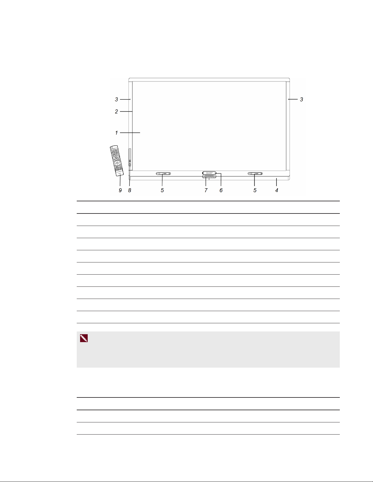
Components
Your interactive flat panel consists of the following components:
No. Name
1 Screen
2 Cameras and reflective tape channel
3 Presence detection sensor (×2)
4 Speakers
5 Pen (×2)
6 Eraser
7 Color select module
8 Front control panel
9 Remote control
N O T E
Components not pictured include the I/O extension module for external PCs, connector panels (see
Connector panels on page 18) and the menu control panel (see Menu control panel on page 44).
Screen
The active screen area specifications vary by model:
Models Diagonal Width Height Aspect ratio
8070i-G4-SMP 70" (178 cm) 61" (154.9 cm) 34 3/8" (87.2 cm) 16:9
8084i-G4-SMP 84" (213.4 cm) 73 1/4" (186.1 cm) 41 1/4" (104.7 cm) 16:9
4 smarttech.com/kb/170446
Page 13
C H A P T E R 1
Welcome
For information on cleaning the screen, see Cleaning the screen on page 50.
Cameras and reflective tape channel
In the corners of the screen, there are cameras that track finger and pen positions across the screen.
The screen is bordered by a channel that contains reflective tape.
For information on cleaning the camera windows and reflective tape, see Cleaning the screen on
page 50.
C A U T I O N
l Keep the reflective tape dry.
l Do not remove or damage the reflective tape.
I M P O R T A N T
l Do not attach items such as adhesive notes to the screen because they will interfere with the
cameras.
l Do not place anything in the channel because it will interfere with the cameras.
Presence detection sensors
The interactive flat panel has two presence detection sensors on its frame that can detect people up
to 16' (5 m) away when the interactive flat panel is in Standby mode.
When the sensors detect motion in the room, the interactive flat panel turns on and displays a
welcome screen. Touching the screen activates the interactive flat panel. When the sensors no
longer detect people in the room, the interactive flat panel returns to Standby mode.
N O T E S
l For information on cleaning your sensors, see Cleaning the presence detection sensors on
page 50.
l Presence detection settings can be changed with the on-screen display menu.
l If ECO Standby mode is enabled for SMARTBoard 8070i-G4-SMP interactive flat panels,
presence detection functionality is limited.
l For more information on the on-screen display menu settings relevant for presence detection,
see page 72 for SMARTBoard 8070i-G4-SMP interactive flat panels or page 80 for
SMARTBoard 8084i-G4-SMP interactive flat panels.
5 smarttech.com/kb/170446
Page 14
C H A P T E R 1
Welcome
Speakers
Your interactive flat panel includes two 10 W integrated front firing speakers. You can connect
external speakers if desired (see Connecting external speakers on page 24).
Pens and eraser
Your interactive flat panel comes with two pens and an eraser.
The bottom bezel of the interactive flat panel includes magnetic holders for the pens and the eraser.
Removing a pen or the eraser from the holders activates it and enables you to either draw or erase
digital ink.
C A U T I O N
When returning the pen or eraser to the magnetic holder, ensure that it is centered on the holder to
prevent it from falling and potentially being damaged.
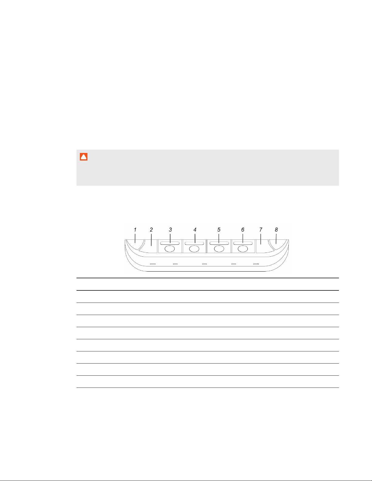
Color select module
The color select module enables you to access Help, open the on-screen keyboard, select pen
colors, right-click and orient the interactive flat panel.
No. Name
1 Help
2 On-screen keyboard
3 Black pen color
4 Red pen color
5 Green pen color
6 Blue pen color
7 Right-click
8 Orient
6 smarttech.com/kb/170446
Page 15
C H A P T E R 1
Welcome
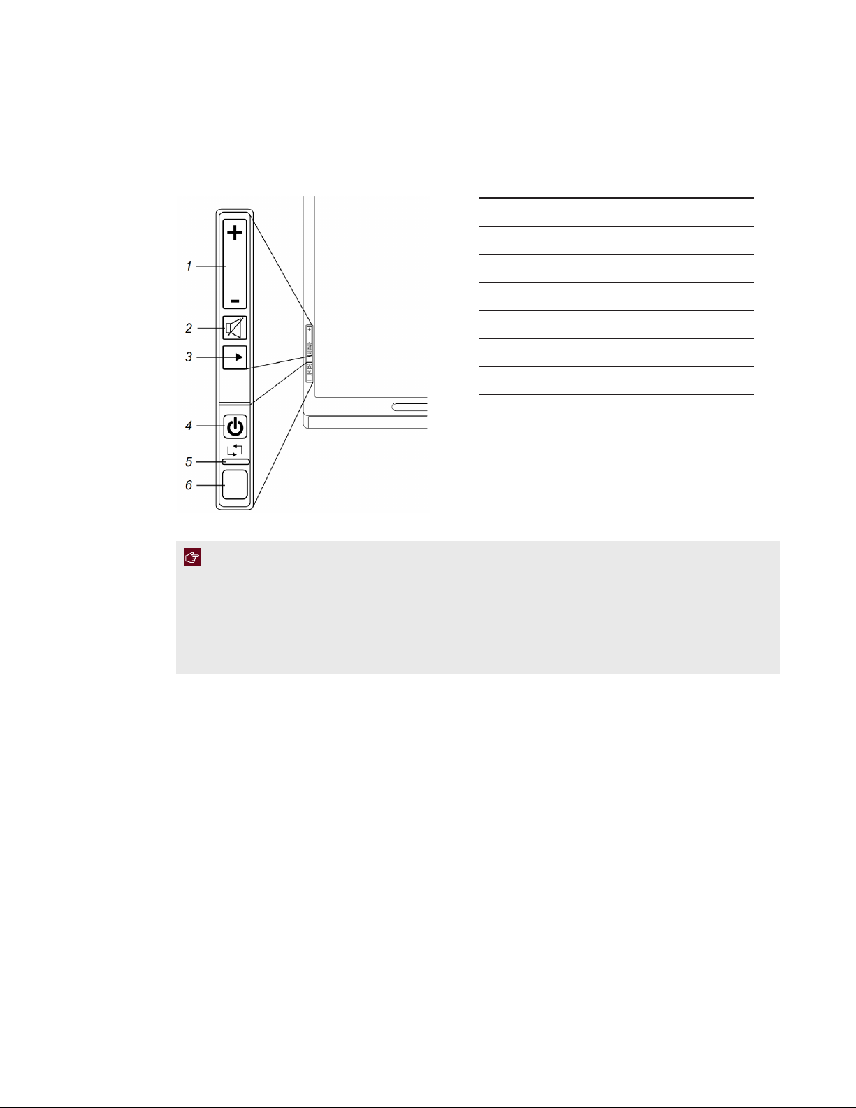
Front control panel
The front control panel contains the volume control, Mute, Input Select and Power/Standby buttons,
as well as the status light and the remote control sensor.
No. Name
1 Volume control
2 Mute button
3 Input Select button
4 Power/Standby button / power light
5 Status light
6 Remote control sensor
I M P O R T A N T
l If there is a film over the front control panel, remove the film before using the front control
panel.
l Do not cover or block the front control panel or you could have reduced use of the remote
control.
In normal use:
l The volume, mute and input buttons are blue.
l The power light is green.
l The status light is green.
For information on diagnosing issues using the front control panel lights, see Resolving blank screen
issues on page 56.
For information on disabling the front control panel for multiple interactive flat panel installations, see
page 72 for SMARTBoard 8070i-G4-SMP interactive flat panels or page 81 for SMARTBoard
8084i-G4-SMP interactive flat panels.
7 smarttech.com/kb/170446
Page 16
C H A P T E R 1
Welcome
Remote control
The remote control enables you to turn on and turn off your interactive flat panel, change the input
source, adjust the volume, access the on-screen menu and more.
For more information on the remote control, see Using the remote control on page 38.
I/O extension module
The I/O extension module is a module that you can install in the OPS slot located on the back of your
interactive flat panel. When installed, the I/O extension module enables you to connect a computer to
your interactive flat panel using the supplied USB and HDMI cables.
Differences between models
SMARTBoard 8000i-G4 series interactive flat panels include the following models:
l SMARTBoard 8070i-G4-SMP interactive flat panel
l SMARTBoard 8084i-G4-SMP interactive flat panel
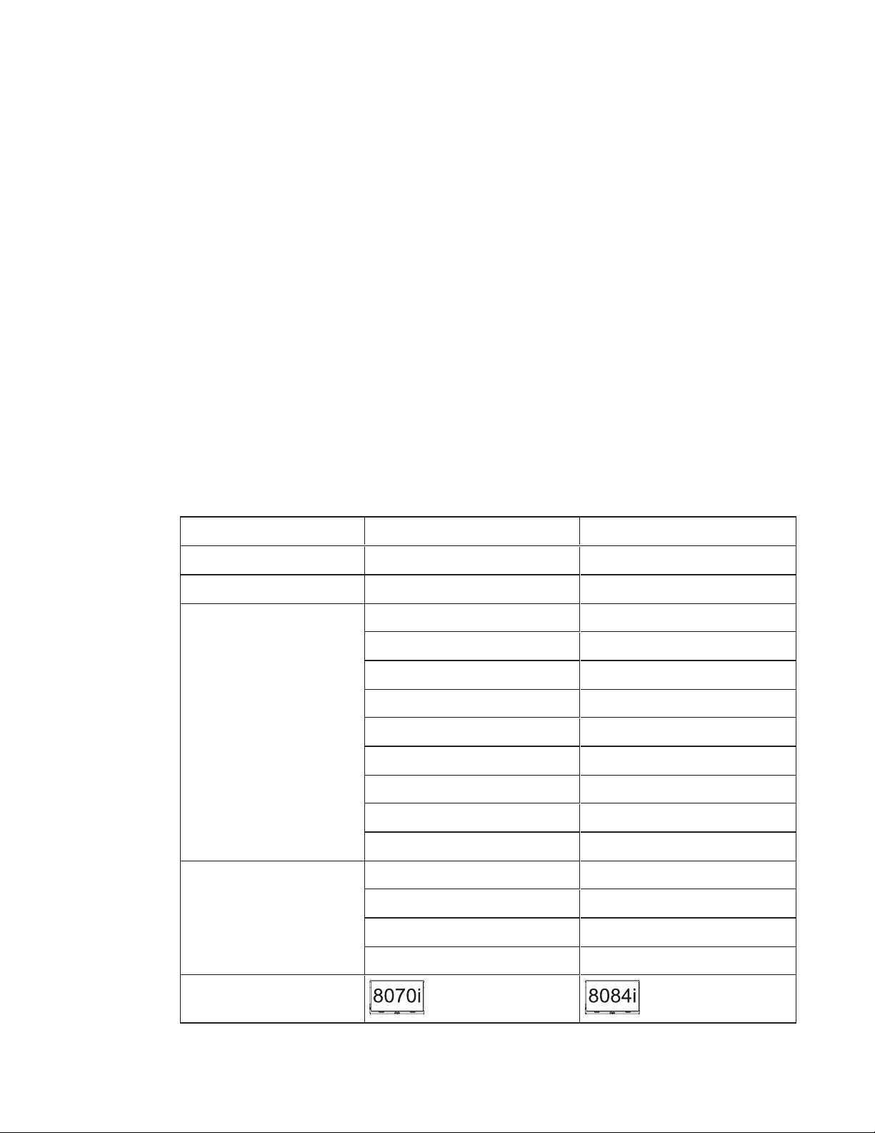
The following table presents the key differences between these models:
Item 8070i-G4-SMP 8084i-G4-SMP
Screen size (diagonal) 70" (178 cm) 84" (213.4 cm)
Computer connections 2 3
Video and audio inputs HDMI (×3)
1
HDMI (×3)
1
DisplayPort DispalyPort
VGA (×2) VGA
DVI-D DVI-D
Component video Component video
Composite video Composite video
S-video
Stereo 3.5 mm Stereo 3.5 mm
Dual RCA audio (×2) Dual RCA audio (×2)
Video and audio outputs VGA DVI-D
Stereo 3.5 mm (×3) Stereo 3.5 mm (×4)
Guide icons
8 smarttech.com/kb/170446
Dual RCA audio
Speaker wire connector Speaker wire connector
Page 17

C H A P T E R 1
Welcome
N O T E S
l Other, minor differences between models are noted throughout this guide.
l Sections in this guide that are relevant to specific models are flagged with the icons defined in
the previous table.
About this guide
This guide explains how to set up and maintain your interactive flat panel. It includes the following
information:
l How to mount your interactive flat panel
l How to connect power and devices, including computers
l How to set up your interactive flat panel and room computer
l What users can do with your interactive flat panel
l How to maintain your interactive flat panel for years of use
l How to troubleshoot issues with your interactive flat panel
In addition, this guide includes information on your interactive flat panel’s on-screen display menu and
remote management support.
This guide is intended for individuals who are responsible for installing and maintaining interactive flat
panels in their organizations. Other documentation and resources are available for individuals who
use interactive flat panels.
Other documentation and resources
In addition to this guide, there are resources for individuals who install, maintain and use interactive
flat panels.
Specifications
Your interactive flat panel’s specifications define the product’s dimensions, weights, recommended
operating and storage temperatures, power requirements and consumption and other important
information for installation and maintenance.
Model Specifications
8070i-G4-SMP smarttech.com/kb/170502
8084i-G4-SMP smarttech.com/kb/170451
9 smarttech.com/kb/170446
Page 18
C H A P T E R 1
Welcome
Installation instructions
Your interactive flat panel comes with installation instructions. These installation instructions explain
how to unpack, assemble and mount your interactive flat panel and how to connect it to computers
and other devices. If you misplaced these installation instructions, you can download a PDFversion
from smarttech.com/kb/170513.
To use your interactive flat panel with a connected computer, you need to install SMART software on
the computer (see SMART software on page 3). If you need to deploy SMART software to multiple
computers on your network, refer to the system administrator’s guide (see
smarttech.com/kb/170518).
Cabling guides
Cabling guides are available to explain how to connect your interactive flat panel to computers and
other devices and how to route cables:
Model Cabling guide
8070i-G4-SMP smarttech.com/kb/170514
8084i-G4-SMP smarttech.com/kb/170515
Help
SMART software includes extensive Help which explains how to use both your interactive flat panel
and the software.
To view SMART software Help on your interactive flat panel
1. Press the Help button on the color select module.
The Help and Support for Your SMARTBoard Interactive Whiteboard window appears.
2. Press Help Center.
The Help appears.
T I P
If you want to view the Help on your smart phone, tablet or other Internet-connected mobile
device, scan the QR code that appears on the home page of the Help with your device’s
camera.
3. Use the Help’s table of contents or search to browse its contents.
10 smarttech.com/kb/170446
Page 19

C H A P T E R 1
Welcome
Training
The SMART training website (smarttech.com/training) includes an extensive library of training
resources you can refer to when first learning to set up or use your interactive flat panel.
Knowledge base
The Support center (smarttech.com/support) includes a knowledge base that you can refer to when
performing maintenance on your interactive flat panel or troubleshooting issues with your interactive
flat panel.
11 smarttech.com/kb/170446
Page 20

Page 21
Chapter 2
flatpanel
Before mounting your interactive flat panel 13
Choosing a location 15
Choosing a height 16
You can either mount your interactive flat panel on a wall, as documented in this chapter, or install it
on a stand as documented in the installation instructions provided with the stand.
To mount your interactive flat panel on a wall, you require a team of professional installers equipped
with a lifting device.
This chapter is intended for installers. Installers should read this chapter along with the installation
instructions included with the interactive flat panel before they mount the interactive flat panel.
W A R N I N G
Improper mounting of your interactive flat panel can result in personal injury and product damage.
Before mounting your interactive flat panel
Do the following before mounting your interactive flat panel:
l Review the environmental requirements in the interactive flat panel’s specifications (see
Specifications on page 9).
l Save all product packaging so that it’s available if you need to transport the interactive flat panel.
If the original packaging isn’t available, you can purchase new product packaging from your
authorized SMART reseller (smarttech.com/where).
13 smarttech.com/kb/170446
Page 22
C H A P T E R 2
Mounting your interactive flatpanel
l Refer to local building codes to ensure the wall can support the weight of the interactive flat
panel and mounting equipment.
Models Weight (lb.) Weight (kg)
8070i-G4-SMP 205 93
8084i-G4-SMP 260 118.3
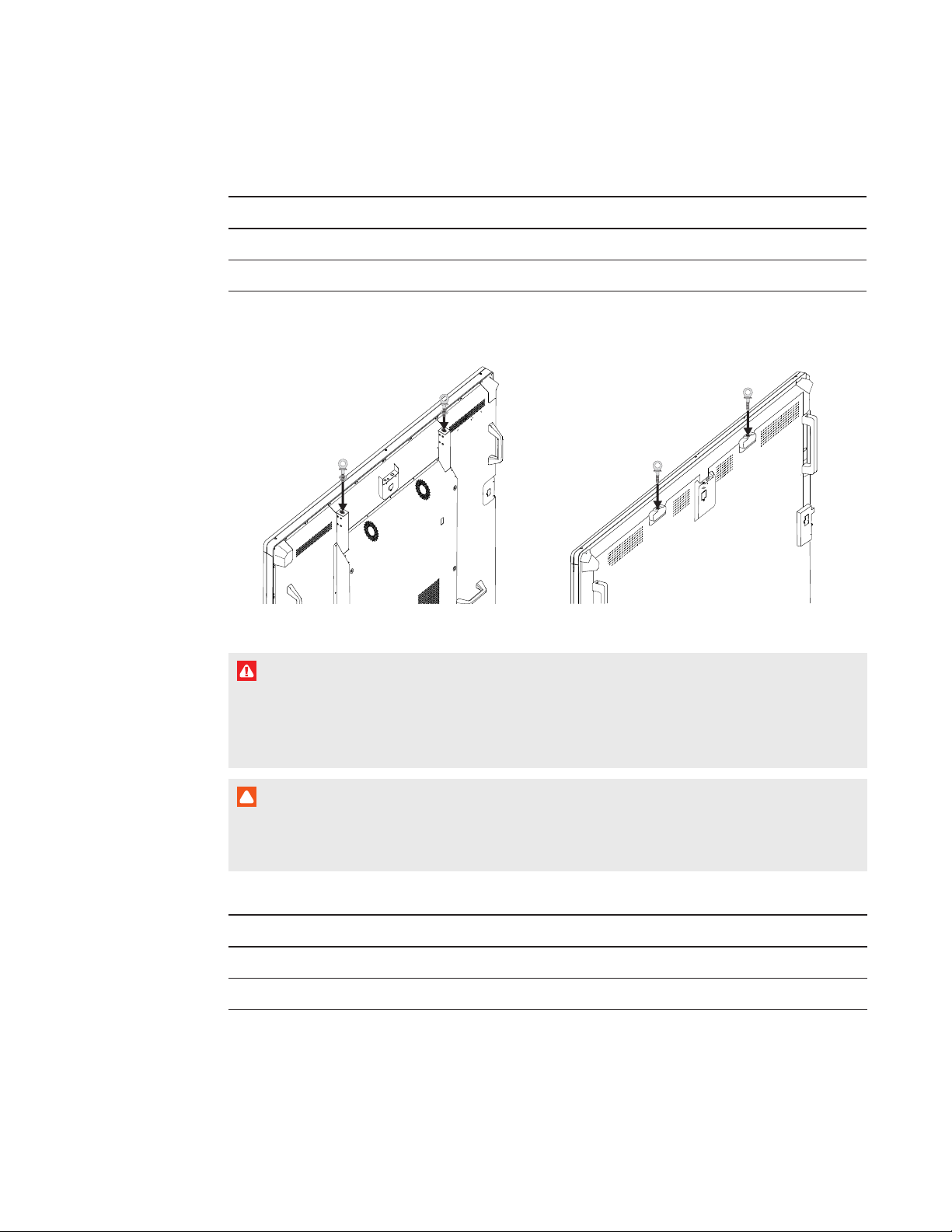
l Attach the included eyebolts and washers to assist in mounting, and remove them after you
mount the interactive flat panel.
8070i-G4-SMP 8084i-G4-SMP
W A R N I N G
Do not attempt to mount or carry the interactive flat panel using your own strength because it
could fall and cause personal injury. Attach a lifting device to the included eyebolts to lift and
carry the interactive flat panel.
C A U T I O N
Hand-tighten the eyebolts. If you over-tighten the eyebolts and damage the threads, you will
be unable to remove the eyebolts.
l Use a standard VESA mounting plate (not included) to mount the interactive flat panel on a wall.
Models Mounting plate
8070i-G4-SMP 800 mm × 400 mm
8084i-G4-SMP 600 mm × 400 mm
14 smarttech.com/kb/170446
Page 23
C H A P T E R 2
Mounting your interactive flatpanel
l Use M8 screws to fasten the wall bracket.
The following table presents the recommended screw length and fasten force for the different
models:
Models Screw length
1
Fasten force
8070i-G4-SMP 23 mm + x mm < M8 < 29 mm + x mm 97.36–123.91 in-lb.
(11–14 N m)
8084i-G4-SMP 23 mm + x mm < M8 < 29 mm + x mm Max. 10.6 in-lb.
(1.2 N m)
C A U T I O N
Do not over-tighten the screws.
N O T E
SMART recommends M8 × 30 mm mounting screws for standard installations where the total
wall mount bracket and washer thickness is less than 7 mm.
l Because the receptacles might not be easily accessible after the installers mount the interactive
flat panel, consider connecting cables for power, computers and other devices while the
interactive flat panel is still in its packaging or is suspended from a lifting device (see Connecting
power and devices on page 17).
l Before turning on the interactive flat panel for the first time, clean the camera windows and
reflective tape following the instructions in Cleaning the camera windows and reflective tape on
page 51.
Choosing a location
Do the following when choosing a location for the interactive flat panel:
l Do not install the interactive flat panel in a location where a door or gate could hit it.
l Do not install the interactive flat panel in an area where it will be subjected to strong vibrations or
dust.
l Do not install the interactive flat panel near where the main power supply enters the building.
l Ensure adequate ventilation or provide air conditioning around the interactive flat panel so that
heat can flow away from the unit and the mounting equipment.
1
Where x is the total thickness of the wall bracket and washer.
15 smarttech.com/kb/170446
Page 24
C H A P T E R 2
Mounting your interactive flatpanel
l If you mount the interactive flat panel in a recessed area, leave at least 4" (10 cm) of space
between the interactive flat panel and the recessed walls to enable ventilation and cooling.
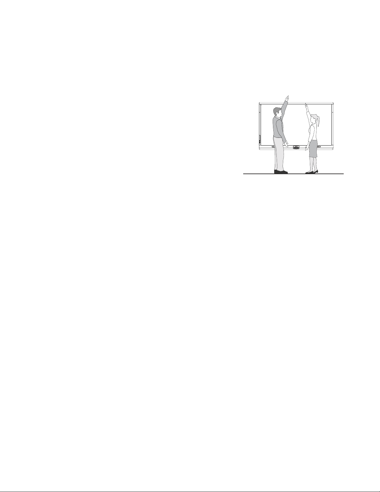
Choosing a height
Consider the general height of the user community when you
choose the height for the interactive flat panel.
16 smarttech.com/kb/170446
Page 25
Chapter 3
Connector panels 18
SMARTBoard8070i-G4-SMP interactive flat panel connectorpanels 18
SMARTBoard8084i-G4-SMP interactive flat panel connectorpanels 20
Connecting power 21
Connecting the room computer 22
Connecting cables for laptops 22
Connecting laptop cables to SMARTBoard 8070i-G4-SMP interactiveflatpanels 22
Connecting laptop cables to SMARTBoard 8084i-G4-SMP interactiveflatpanels 23
Connecting external speakers 24
Connecting other devices 24
Disabling the USB receptacles 24
This chapter includes information on connecting your interactive flat panel to power, computers and
other devices.
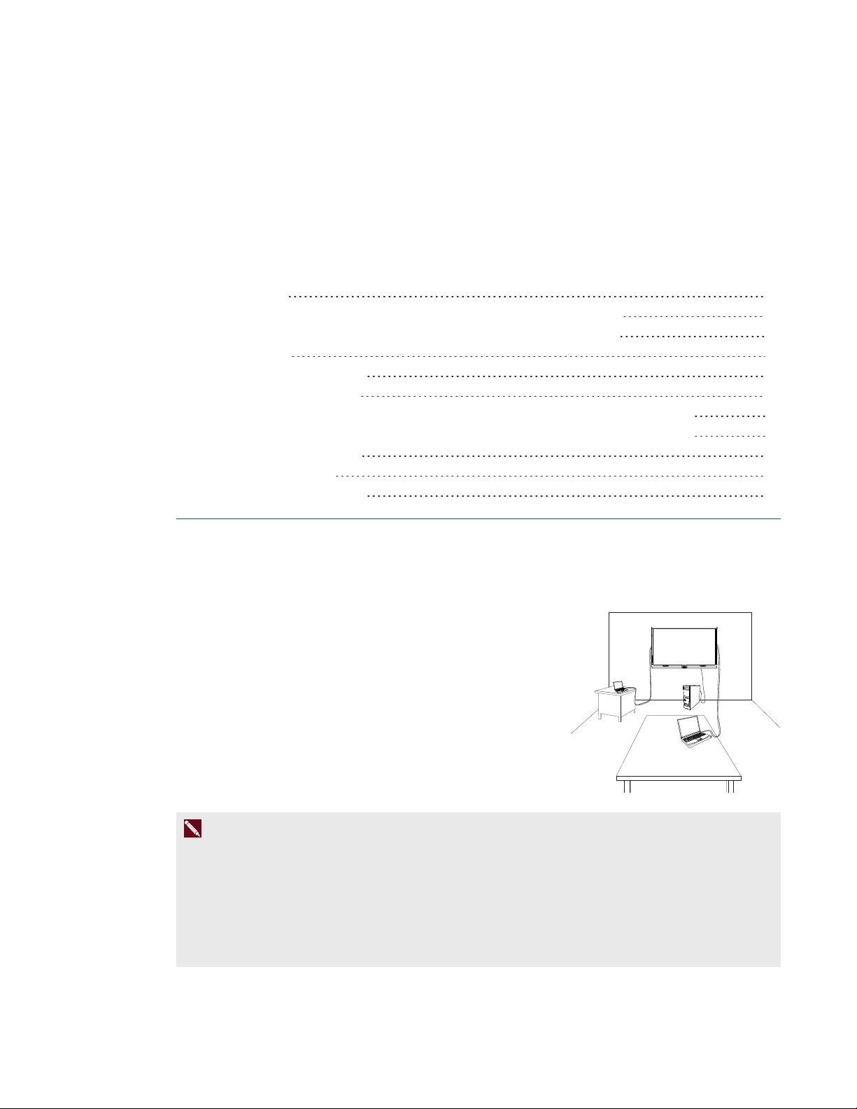
In a typical installation, you connect your interactive flat panel to a
room computer and up to one guest laptop (SMARTBoard
8070i-G4-SMP interactive flat panels) or to a room computer and
up to two guest laptops (SMARTBoard 8084i-G4-SMP interactive
flat panels). You can also connect external speakers, DVD
players, document cameras and other devices.
N O T E S
l This chapter assumes that you installed the I/O extension module (see Installation
instructions on page 10).
l The connections in this chapter are based on the default USB mappings. However, you can
customize these mappings (see page 73 for SMARTBoard 8070i-G4-SMP interactive flat
panels or page 81 for SMARTBoard 8084i-G4-SMP interactive flat panels).
17 smarttech.com/kb/170446
Page 26
C H A P T E R 3
Connecting power and devices
Connector panels
There are connector panels on the top, left, right and bottom of your interactive flat panel as well as on
the I/O extension module.
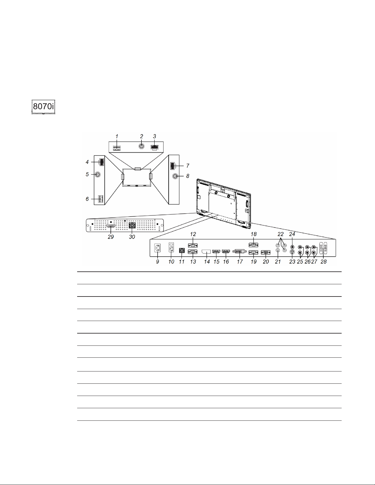
SMARTBoard8070i-G4-SMP interactive flat panel connectorpanels
The following diagram and table present the connectors on SMARTBoard 8070i-G4-SMP interactive
flat panels:
No. Type Details Identifier
Top connector panel
1 USB USB 3.0 Type-A receptacle
2 Audio out Stereo 3.5 connector
3 DC power 19V DC Molex® Micro-Fit 2-pin connector
Left connector panel
4 DC power 19V DC Molex Micro-Fit 2-pin connector
5
6 USB USB 2.0 Type-A receptacle
Right connector panel
7 DC power 19V DC Molex Micro-Fit 2-pin connector
8 Audio out Stereo 3.5 mm connector
Audio out
Stereo 3.5 mm connector
18 smarttech.com/kb/170446
Page 27

C H A P T E R 3
Connecting power and devices
No. Type Details Identifier
Bottom connector panel
9 AC power AC power pass-through
10 AC power AC power inlet and switch
11 USB USB 2.0 Type-B receptacle USB2
12 Room control in RS-232 connector
13 Room control out /
RS-232 connector
pass-through
14 Video in DisplayPort connector DPORT
15 Video in HDMI connector HDMI1
16 Video in HDMI connector HDMI2
17 Video in DVI-D connector DVI
18 Video in VGA connector VGA1
19 Video in VGA connector VGA2
20 Video out VGA connector
21 Video in Composite video receptacle DVD/HD
22 Video in Component video (Y, Pb/Cb, Pr/Cr)
VIDEO
receptacles
23 Video in S-video connector S-VIDEO
24 Audio in Stereo 3.5 mm connector AUDIO1
25 Audio in Dual RCA audio receptacles AUDIO2
26 Audio in Dual RCA audio receptacles AUDIO3
27 Audio out Dual RCA audio receptacle
28 Audio out Speaker wire connectors
I/O extension module
29 Video in HDMI connector HDMI3/PC
30 USB USB 2.0 Type-B receptacle USB1
19 smarttech.com/kb/170446
Page 28
C H A P T E R 3
Connecting power and devices
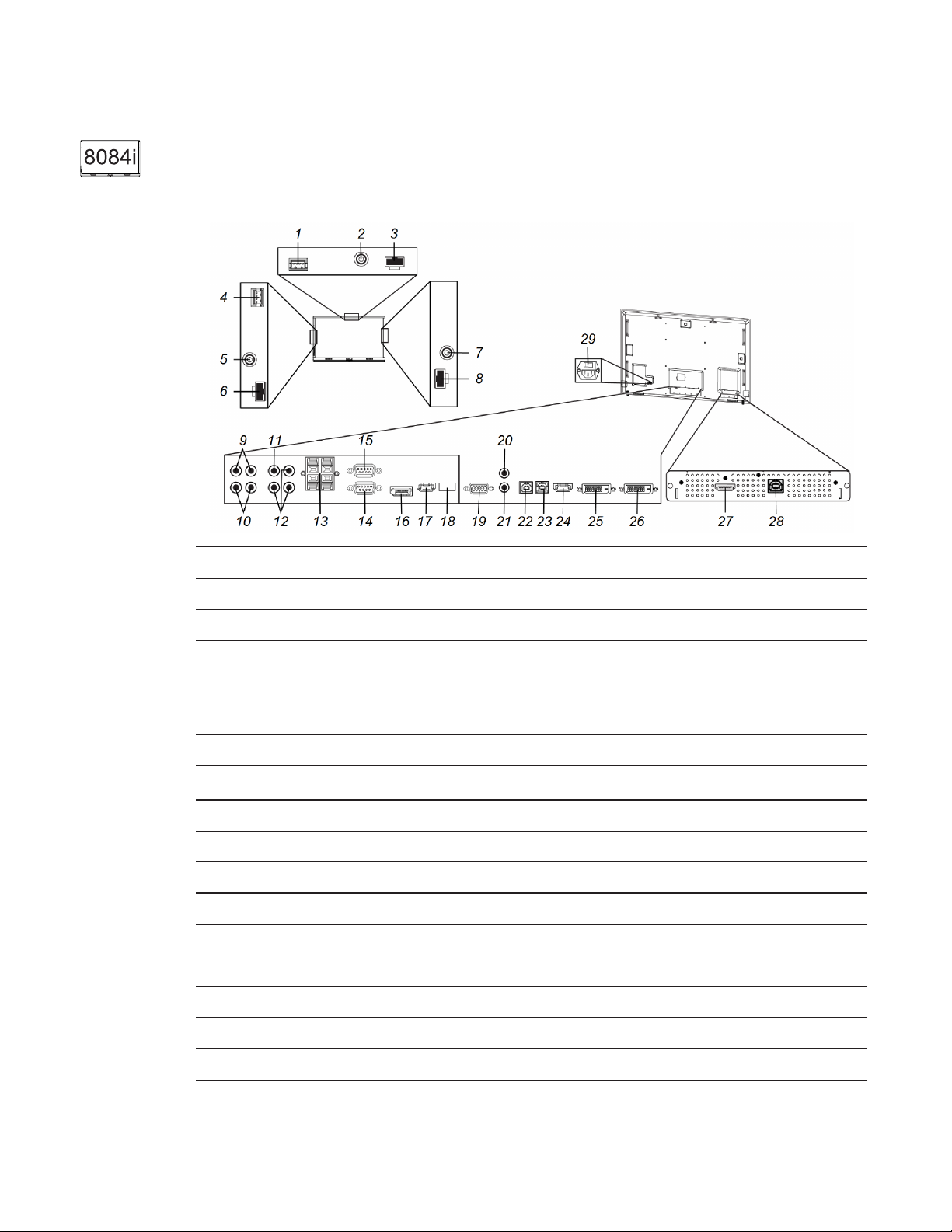
SMARTBoard8084i-G4-SMP interactive flat panel connectorpanels
The following diagram and table present the connectors on SMARTBoard 8084i-G4-SMP interactive
flat panels:
No. Type Details Identifier
Top connector panel
1 USB USB 3.0 Type-A receptacle
2 Audio out Stereo 3.5 connector
3 DC power 19V DC Molex Micro-Fit 2-pin connector
Left connector panel
4 USB USB 2.0 Type-A receptacle
5
Audio out
Stereo 3.5 mm connector
6 DC power 19V DC Molex Micro-Fit 2-pin connector
Right connector panel
7 Audio out Stereo 3.5 mm connector
8 DC power 19V DC Molex Micro-Fit 2-pin connector
Bottom connector panel
9 Audio in Dual RCA audio receptacles AUDIO2
10 Audio in Dual RCA audio receptacles AUDIO3
11 Video in Composite video receptacle Composite
12 Video in Component video (Y, Pb, Pr) receptacles Component
20 smarttech.com/kb/170446
Page 29

C H A P T E R 3
Connecting power and devices
No. Type Details Identifier
13 Audio out Speaker wire connectors
14 Room control in RS-232 connector
15 Room control out /
pass-through
16 Video in DisplayPort connector DPORT
17 Video in HDMI connector HDMI2
18 Service USB 2.0 Type-A receptacle
19 Video in VGA connector VGA
20 Audio in Stereo 3.5 mm connector AUDIO1
21 Audio out Stereo 3.5 mm connector
22 USB USB 2.0 Type-B receptacle USB2
23 USB USB 2.0 Type-B receptacle USB3
24 Video in HDMI connector HDMI1
25 Video in DVI-D connector DVI-D
26 Video out DVI-D connector
I/O extension module
27 Video in HDMI connector HDMI3/PC
RS-232 connector
28 USB USB 2.0 Type-B receptacle USB1
Back of the interactive flat panel
29 AC power AC power inlet and switch
Connecting power
Connect the supplied power cable from the AC power inlet on the bottom connector panel
(SMARTBoard 8070i-G4-SMP interactive flat panels) or on the back of the interactive flat panel
(SMARTBoard 8084i-G4-SMP interactive flat panels) to a power outlet.
N O T E
Refer to your interactive flat panel’s specifications for power requirements and power consumption
information (see Specifications on page 9).
21 smarttech.com/kb/170446
Page 30
C H A P T E R 3
Connecting power and devices
Connecting the room computer
Using the supplied USB and HDMI cables, connect the room computer to the USB1 receptacle and
the HDMI3/PC connector on the I/O extension module, which is located on the back of your
interactive flat panel.
8070i-G4-SMP 8084i-G4-SMP
N O T E
SMARTBoard 8084i-G4-SMP interactive flat panels support 4K UHD (3840×2160). However, you
can only connect computers and other devices that output this resolution to the HDMI1 and HDMI2
connectors on the bottom connector panel, not the HDMI3/PC connector on the I/O extension
module. You can customize the USB mappings to map the USB1 receptacle on the I/O extension
module to the HDMI1 or HDMI2 connectors on the bottom connector panel (see page 81).
Connecting cables for laptops
You can install cables that enable users to connect laptops to your interactive flat panel from another
location in the room, such as on a conference table. By installing these cables, you make use of
connectors that might not be accessible when your interactive flat panel is wall-mounted.
You can then run the cables across floors or behind walls to the conference table.
W A R N I N G
Ensure that any cables extending across the floor to your SMART product are properly bundled and
marked to avoid a trip hazard.
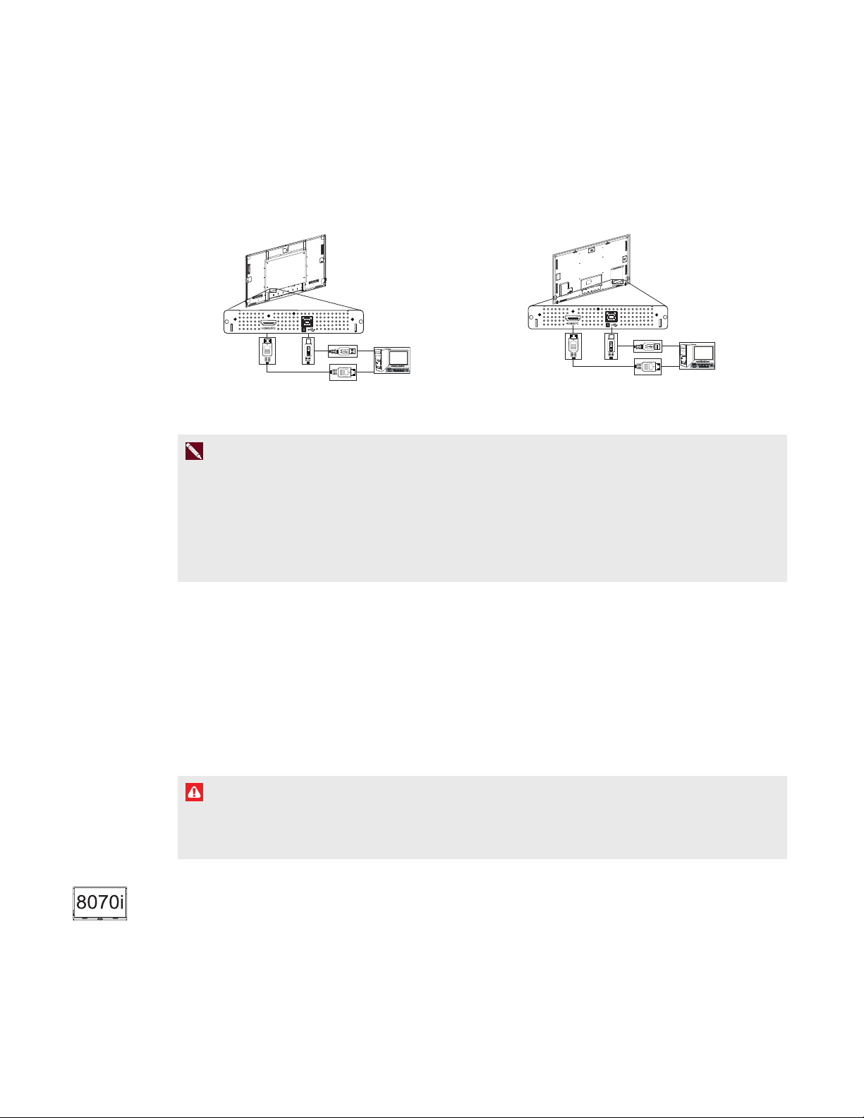
Connecting laptop cables to SMARTBoard 8070i-G4-SMP
interactiveflatpanels
You can connect up to one laptop to a SMARTBoard 8070i-G4-SMP interactive flat panel.
22 smarttech.com/kb/170446
Page 31

C H A P T E R 3
Connecting power and devices
For this laptop:
l Connect a USB cable to the USB2 receptacle
on the bottom connector panel.
l Connect an HDMI cable to the HDMI2
connector on the bottom connector panel.
N O T E
You can use the provided CAT 5 USB extender to extend the USB connection between the
interactive flat panel and a laptop.
Connecting laptop cables to SMARTBoard 8084i-G4-SMP
interactiveflatpanels
You can connect up to two laptops to a SMARTBoard 8084i-G4-SMP interactive flat panel.
For the first laptop:
l Connect a USB cable to the USB2 receptacle on the
bottom connector panel.
l Connect an HDMI cable to the HDMI2 connector on
the bottom connector panel.
For the second laptop:
l Connect a USB cable to the USB3 receptacle on the
bottom connector panel.
l Connect a DVI cable to the DVI-D connector on the
bottom connector panel.
N O T E
You can use the provided CAT 5 USB extender to extend the USB connection between the
interactive flat panel and a laptop.
23 smarttech.com/kb/170446
Page 32

C H A P T E R 3
Connecting power and devices
Connecting external speakers
Your interactive flat panel includes two 10 W speakers below the screen. You can connect external
speakers using the stereo 3.5 mm connectors on either side of the interactive flat panel.
Alternatively, you can use the speaker wire connectors on the bottom connector panel.
Connecting other devices
You can connect other devices such as DVD players and document cameras to your interactive flat
panel using the video and audio input connectors on the bottom connector panel.
N O T E S
l For SMARTBoard 8070i-G4-SMP interactive flat panel, users can specify the current audio by
selecting it in the on-screen display menu or by pressing the AUDIOINPUT button on the
remote control (see page 71).
l For SMARTBoard 8084i-G4-SMP interactive flat panels, video input connectors are mapped
to audio input connectors:
Video Audio
VGA AUDIO1 (stereo 3.5 mm)
DVI-D AUDIO2 (dual RCA audio)
Component video AUDIO3 (dual RCA audio)
You can change these mappings in the on-screen display menu (see page 78).
Disabling the USB receptacles
The top and left connector panels include USB Type-A receptacles. You can disable these
receptacles so that they can’t access computers connected to your interactive flat panel.
C A U T I O N
l Disconnect the power supply for your interactive flat panel before you disable the USB
receptacles.
l Complete the following procedure in a static-free environment to prevent electrostatic shock
and damage to the interactive flat panel.
24 smarttech.com/kb/170446
Page 33

C H A P T E R 3
Connecting power and devices
To disable the USB receptacles
1. Locate the rectangular cut-out on the back of the top connector panel.
2. Remove the screw securing the cut-out with a Phillips screwdriver. Retain
the screw and cut-out.
3. Locate the black jumper on the circuit board inside the panel.
4. Pull the black jumper off of the circuit board with pliers.
C A U T I O N
To prevent damage, do not touch the circuit board with the pliers.
N O T E
You can install the jumper again to enable the USB receptacle.
5. Repeat steps 1 to 4 for the left connector panel.
25 smarttech.com/kb/170446
Page 34

Page 35

Chapter 4
flatpanel and room computer
Turning on your interactive flat panel and roomcomputer for the first time 27
Installing SMART software 28
Downloading and installing SMART software 28
Deploying SMART software to multiple computers 28
Running the connection wizard 28
This chapter explains how to set up your interactive flat panel and room computer after mounting your
interactive flat panel and connecting power and devices.
Turning on your interactive flat panel and
roomcomputer for the first time
After connecting your room computer to the interactive flat panel (see Connecting the room computer
on page 22) and mounting the interactive flat panel (see Mounting your interactive flatpanel on page
13), you can turn on both devices.
To turn on your interactive flat panel and room computer for the first time
1. Turn on your room computer.
2. Turn on your interactive flat panel by flicking the power switch beside the AC power inlet.
3.
Press the Power/Standby button on the front control panel.
4.
Press the Input Select button on the front control panel until the input source is HDMI3/PC.
T I P
Alternatively, you can press the power and input buttons on the remote control (see Remote
control buttons on page 40).
27 smarttech.com/kb/170446
Page 36

C H A P T E R 4
Setting up your interactive flatpanel and room computer
Installing SMART software
To take full advantage of your interactive flat panel’s features, you must download and install SMART
software on your room computer.
Downloading and installing SMART software
To download and install SMART software
1. Go to smarttech.com/downloads.
2. Scroll to the SMART Meeting Pro software section.
3. Click Choose a version, and then select the most recent version.
4. Click Download.
5. Follow the on-screen instructions to save the installer to a temporary location.
6. Double-click the installer.
7. Follow the on-screen instructions to install SMART software.
Deploying SMART software to multiple computers
You may need to deploy SMART software to multiple computers in the following situations:
l Your organization has multiple interactive flat panels, each with its own room computer.
l You want to deploy SMART software to users’ laptops so that they can use their laptops with
your interactive flat panel.
To deploy your interactive flat panels to multiple computers, refer to the appropriate system
administrator’s guide (see Installation instructions on page 10).
Running the connection wizard
After turning on your interactive flat panel and room computer for the first time and installing SMART
software, run the connection wizard to calibrate and orient the interactive flat panel.
To run the connection wizard
1. Press the Help button on the color select module.
The Help and Support for Your SMARTBoard Interactive Whiteboard window appears.
28 smarttech.com/kb/170446
Page 37

C H A P T E R 4
Setting up your interactive flatpanel and room computer
2. Press Connection Wizard.
The SMART Connection Wizard appears.
3. Select the interactive flat panel from the list of connected SMART interactive products, and then
press Next.
4. Select Product is being set up for the first time, and then press Next.
5. Follow the on-screen instructions to calibrate and orient the interactive flat panel for the
firsttime.
29 smarttech.com/kb/170446
Page 38

Page 39

Chapter 5
Turning on and turning off your interactiveflatpanel 31
Turning on and turning off SMARTBoard 8070i-G4-SMP interactiveflatpanels 32
Turning on and turning off SMARTBoard 8084i-G4-SMP interactiveflatpanels 33
Using presence detection 33
Using your interactive flat panel with the roomcomputer 34
Using SMART software 34
Using the USB receptacle 34
Using your interactive flat panel with guestlaptops 35
Connecting a guest laptop directly to your interactive flat panel 35
Connecting a guest laptop through a SMARTGoWire cable 36
Changing input sources 37
Using the remote control 38
Remote control sensor 39
Remote control buttons 40
SMARTBoard8070i-G4-SMP interactive flat panel remote control 40
SMARTBoard8084i-G4-SMP interactive flat panel remote control 42
Menu control panel 44
This chapter explains how to use the key features of your interactive flat panel.
Turning on and turning off your
interactiveflatpanel
You can turn on and turn off your interactive flat panel using the front control panel or the remote
control.
N O T E
If presence detection is enabled, the interactive flat panel turns on and turns off automatically (see
Using presence detection on page 33).
31 smarttech.com/kb/170446
Page 40

C H A P T E R 5
Using your interactive flat panel
Turning on and turning off SMARTBoard 8070i-G4-SMP
interactiveflatpanels
To turn on your interactive flat panel
1. Turn on your computer.
Press the Power/Standby button on the front control panel.
2.
OR
Press the POWER ON button on the remote control.
Your computer’s logon screen or desktop appears on your interactive flat panel.
I M P O R T A N T
If the power light on the front control panel is off, either the interactive flat panel is not plugged
in or the main power switch on the bottom connector panel is turned off. To find the main power
switch, see Connector panels on page 18.
To turn off your interactive flat panel
1. Turn off your computer.
Press the Power/Standby button on the front control panel.
2.
OR
Press the STANDBY button on the remote control.
32 smarttech.com/kb/170446
Page 41

C H A P T E R 5
Using your interactive flat panel
Turning on and turning off SMARTBoard 8084i-G4-SMP
interactiveflatpanels
To turn on your interactive flat panel
1. Turn on your computer.
Press the Power/Standby button on the front control panel.
2.
OR
Press the POWER button or the MONITORON button on the remote control.
Your computer’s logon screen or desktop appears on your interactive flat panel.
I M P O R T A N T
If the power light on the front control panel is off, either the interactive flat panel is not plugged
in or the main power switch on the back of the interactive flat panel is turned off. To find the
main power switch, see Connector panels on page 18.
To turn off your interactive flat panel
1. Turn off your computer.
Press the Power/Standby button on the front control panel.
2.
OR
Press the POWER button or the MONITOROFF button on the remote control.
Using presence detection
Your interactive flat panel has two
presence detection sensors on its frame
that can detect people up to 16' (5 m)
away when the interactive flat panel is in
Standby mode.
When the sensors detect motion in the
room, the interactive flat panel turns on
and displays a welcome screen.
Touching the screen activates the
interactive flat panel. When the sensors
no longer detect people in the room, the interactive flat panel returns to Standby mode.
33 smarttech.com/kb/170446
Page 42

C H A P T E R 5
Using your interactive flat panel
N O T E
If ECOStandby mode is enabled for SMARTBoard 8070i-G4-SMP interactive flat panels,
presence detection functionality is limited.
Presence detection settings can be changed with the on-screen display menu.
For more information on the on-screen display menu settings relevant for presence detection, see
page 72 for SMARTBoard 8070i-G4-SMP interactive flat panels or page 80 for SMARTBoard
8084i-G4-SMP interactive flat panels.
For information on cleaning your sensors, see Cleaning the presence detection sensors on page 50.
Using your interactive flat panel with the
roomcomputer
Users will most often use the interactive flat panel with the room computer you set up in the previous
chapter (see Setting up your interactive flatpanel and room computer on page 27).
Using SMART software
The SMART software installed on the room computer allows users to do the following:
l Interact with objects on the screen by touching them
l Write, draw and erase digital ink
l Use multitouch gestures to browse pages, zoom in and out, and resize, rotate, group, ungroup
and flick objects
l Create and participate in collaborative meetings
For more information on the software and how you can use it with your interactive flat panel, refer to
the Help (see Help on page 10).
Using the USB receptacle
You can connect a USB drive or device to
the USB Type-A receptacles on the left
connector panel of your interactive flat panel,
and then access it from the room computer.
34 smarttech.com/kb/170446
Page 43

C H A P T E R 5
Using your interactive flat panel
N O T E S
l The room computer must be connected to the USB1 receptacle on the I/O extension module.
l You can disable the USB receptacle (see Disabling the USB receptacles on page 24).
To use the USB receptacle
1. If the room computer’s display isn’t visible on the interactive flat panel, change to the HDMI3/PC
input source (see Changing input sources on page 37).
2. Connect a USB device to the USB Type-A receptacle.
3. Use the room computer to access the content on your USBdevice.
Using your interactive flat panel with
guestlaptops
Users can connect up to one guest laptop to SMARTBoard 8070i-G4-SMP interactive flat panels or
up to two guest laptops to SMARTBoard 8084i-G4-SMP interactive flat panels using the cables you
installed (see Connecting cables for laptops on page 22).
Connecting a guest laptop directly to your interactive flat panel
When a user connects a guest laptop to the interactive flat panel, the laptop’s desktop is displayed on
the interactive flat panel and touch interactivity is enabled if SMART software is installed (see
Installing SMART software on page 28).
N O T E
If SMART software isn’t installed, you can connect the laptop to the interactive flat panel through a
SMARTGoWire cable (see Connecting a guest laptop through a SMARTGoWire cable on the next
page).
To connect a guest laptop to the HDMI2 input source
1. Connect the USB cable from the interactive flat panel’s USB2 receptacle to the guest laptop.
2. Connect the HDMI cable from the interactive flat panel’s HDMI2 connector to the guest laptop.
3. Turn on the laptop.
35 smarttech.com/kb/170446
Page 44

C H A P T E R 5
Using your interactive flat panel
4.
Press the Input Select button on the front control panel until the input source is HDMI2.
T I P
Alternatively, you can press the Input button on the remote control (see Remote control
buttons on page 40).
To connect a guest laptop to the DVI-D input source (SMARTBoard 8084i-G4-SMP
interactive flat panels only)
1. Connect the USB cable from the interactive flat panel’s USB3 receptacle to the guest laptop.
2. Connect the DVI cable from the interactive flat panel’s DVI-D connector to the guest laptop.
3. Turn on the laptop.
4.
Press the Input Select button on the front control panel until the input source is DVI-D.
T I P
Alternatively, you can press the Input button on the remote control (see Remote control
buttons on page 40).
Connecting a guest laptop through a SMARTGoWire cable
If you want to connect a laptop that doesn’t have SMARTsoftware installed, you can use a
SMARTGoWire cable. The SMARTGoWire cable enables you to have touch control of the laptop
and use SMARTMeetingPro PE software without installing the software on the laptop.
I M P O R T A N T
Your interactive flat panel supports the SMARTGoWire cable with SMARTMeetingPro PE
software only. It does not support the SMARTGoWire cable with SMARTNotebook™
collaborative learning software.
To connect a SMARTGoWire cable
1. Connect the guest laptop to the interactive flat panel as described in Connecting a guest laptop
directly to your interactive flat panel on the previous page.
36 smarttech.com/kb/170446
Page 45

C H A P T E R 5
Using your interactive flat panel
2. Disconnect the USB cable from your laptop, and then connect it to the SMARTGoWire cable’s
USB receptacle.
N O T E
If the SMARTGoWire cable isn’t connected to your interactive flat panel through a USB cable,
you have access to SMARTMeetingPro PE software on your laptop for five minutes, and
then the software closes.
3. Connect the SMARTGoWire cable’s USB connector to your laptop.
The AutoPlay dialog box appears.
4. Select Start SMART Meeting Pro PE.
SMARTMeetingPro PE software starts. You have touch control of your laptop on your
interactive flat panel and can use SMARTMeetingPro PE software while your laptop is
connected to your interactive flat panel.
To disconnect a SMARTGoWire cable
1. If required, save your SMARTMeetingPro software file to your laptop. You can save the file as
an .fcw file.
N O T E
You can open an .fcw file on a computer that has SMARTMeetingPro software or
SMARTMeetingPro PE software or that is connected to a SMART product through a
SMARTGoWire cable.
2. Close SMARTMeetingPro PE software.
3. Disconnect the SMARTGoWire cable from your laptop and the USB cable.
Changing input sources
You can connect the interactive flat panel to a room computer, one or two guest laptops and other
devices (see Connecting power and devices on page 17).
You can display a device’s input source by pressing the Input Select button on the front control
panel until the device’s input appears on the interactive flat panel. Alternatively, you can press the
Input button on the remote control.
37 smarttech.com/kb/170446
Page 46

C H A P T E R 5
Using your interactive flat panel
T I P
The remote control for SMARTBoard 8070i-G4-SMP interactive flat panels has buttons for each
input source (HDMI1, HDMI2, HDMI3/PC and so on). Press one of these input source buttons to
display the connected device’s input.
Using the remote control
The infrared remote control enables you to turn on and turn off your interactive flat panel, change the
input source, change the volume and more. You can also use the remote control to open the
on-screen display menu and then change the interactive flat panel’s settings.
If the remote control doesn’t respond, see Resolving remote control issues on page 63.
C A U T I O N
l Do not subject the remote control to strong shock.
l Keep the remote control away from liquids. If it gets wet, wipe it dry immediately.
l Do not expose the remote control to heat or steam.
l Do not open any part of the remote control other than the battery compartment and
picture-in-picture compartment.
I M P O R T A N T
The remote control system does not function when strong light strikes the remote control sensor or
when there is an object between the remote control and its sensor.
38 smarttech.com/kb/170446
Page 47

C H A P T E R 5
Using your interactive flat panel
Remote control sensor
The remote control sensor is located on the front control panel. It
enables you to control your interactive flat panel from an angle of
30º and within a distance of 23' (7 m) using the included remote
control.
I M P O R T A N T
The remote control might not function when the infrared remote control sensor is blocked or when it
is in direct sunlight or strong lighting.
39 smarttech.com/kb/170446
Page 48

C H A P T E R 5
Using your interactive flat panel
Remote control buttons
The remote control enables you to access on-screen menus and to change display and input settings.
SMARTBoard8070i-G4-SMP interactive flat panel remote control
No. Name Description
1 POWER ON Turn on your interactive flat panel
2 ASPECT Select the aspect ratio
3 STILL Turn on or off the still picture mode
40 smarttech.com/kb/170446
Page 49

C H A P T E R 5
Using your interactive flat panel
No. Name Description
4 [Number buttons] Press buttons on the number pad to set and change passwords,
change channels or customize or change settings
5 DISPLAY Display the information menu
6 SET Open a selected menu option in the on-screen display menu
7 [Left and right buttons] Change the value of the selected menu option in the on-screen
display menu
8 AUTO SET UP Automatically set the H position, V position and clock phase (for
VGA video inputs only)
9 VOL +/- Increase or decrease the audio output level
10 AUDIOINPUT Select the audio input source
11 [Input buttons] Select a specific video input
12 SLEEP Set a timer to turn off the interactive flat panel
13 INPUT Switch video inputs
14 SOUND Select artificial surround sound
15 MUTE Mute audio inputs for your interactive flat panel
16 EXIT Close the on-screen display menu
17 [Up and down buttons] Select a menu option in the on-screen display menu
18 MENU Display the on-screen display menu
19 * [Not in use]
20 PICTURE MODE Select the picture mode
21 MTS [Not in use]
22 STANDBY Turn off your interactive flat panel (in Standby mode)
41 smarttech.com/kb/170446
Page 50

C H A P T E R 5
Using your interactive flat panel
SMARTBoard8084i-G4-SMP interactive flat panel remote control
No. Name Description
1 POWER Turn on or off your interactive flat panel
2 MONITOR Alternate between different interactive flat panel modes
(on,offandStandby) depending on how you have configured
Standby mode
3 [Number buttons] Press buttons on the number pad to set and change passwords,
or to customize or change settings
42 smarttech.com/kb/170446
Page 51

C H A P T E R 5
Using your interactive flat panel
No. Name Description
4 1/a/A Switch the number pad between number input (1,2,3),
lowercase letter input (a,b,c) and uppercase letter input
(A,B,C)
5 MARK/ARC Set the aspect ratio
6 VOL +/- Increase or decrease audio output level
7 MUTE Mute audio inputs for your interactive flat panel
8 MENU Display the on-screen display menu
9 [Up, down, left and
right buttons]
Select a menu option in the on-screen display menu, and then
change the value of the selected menu option
10 OK Open a selected menu option in the on-screen display menu
11 BACK Return to the previous screen in the on-screen display menu
12 [Not in use]
13 [Video buttons] Play, pause, stop, fast forward and rewind video
14 TILE [Not in use]
15 EXIT Close the on-screen display menu
16 [Not in use]
17 AUTO Automatically set the H position, V position and clock phase (for
VGA video inputs only)
18 BRIGHTNESS Increase or decrease brightness
19 PSM Set the picture mode, sound mode and sleep timer
20 CLEAR Clear number or letter input
21 INPUT Switch video inputs
22 ENERGY SAVINGS [For future use]
43 smarttech.com/kb/170446
Page 52

C H A P T E R 5
Using your interactive flat panel
Menu control panel
As an alternative to using your remote control to navigate the on-screen display menu, you can use
the menu control panel located on the bottom of your interactive flat panel.
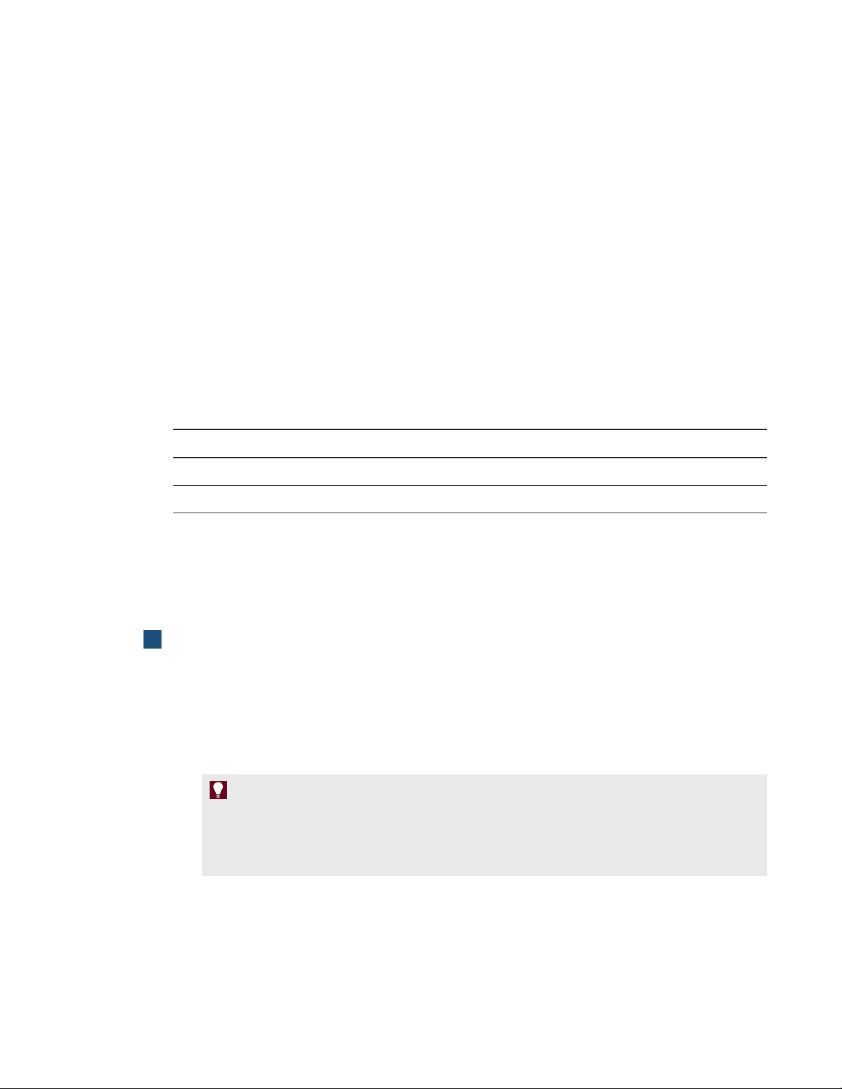
SMARTBoard 8070i-G4-SMP interactive flat panels
No. Name
1 MENU
2 SET
3 [Up]
4 [Down]
5 [Left]
6 [Right]
SMARTBoard 8084i-G4-SMP interactive flat panels
No. Name
1 MENU
2 OK
3 [Up]
4 [Down]
5 [Left]
6 [Right]
44 smarttech.com/kb/170446
Page 53

Chapter 6
interactiveflatpanel
Opening SMARTSettings 45
Updating software 46
Updating firmware 46
Calibrating your interactive flat panel 47
Orienting your interactive flat panel 48
Replacing batteries in the remote control 49
Replacing a pen nib 49
Cleaning the screen 50
Cleaning the presence detection sensors 50
Cleaning the camera windows and reflective tape 51
Maintaining ventilation 51
Preventing condensation 52
Checking the interactive flat panel installation 52
Removing your interactive flat panel 52
Transporting your interactive flat panel 53
If you properly maintain your interactive flat panel, it will provide years of use.
Opening SMARTSettings
Several maintenance and troubleshooting procedures in this guide require you to open
SMARTSettings.
To open SMARTSettings on Windows 7 operating systems
Select Start > All Programs > SMART Technologies > SMART Tools > SMART Settings.
SMARTSettings appears.
45 smarttech.com/kb/170446
Page 54

C H A P T E R 6
Maintaining your interactiveflatpanel
To open SMARTSettings on Windows 8 operating systems
1. Open the Apps screen.
2. Press SMARTSettings.
SMARTSettings appears.
Updating software
SMARTProductUpdate (SPU) is included in the SMART software you installed to use your
interactive flat panel (see Installing SMART software on page 28). SPU periodically checks for
updates to the SMART software posted on the SMART website. You can configure SPU to prompt
users to install updates or to install updates automatically.
For more information on SPU, search for “SMART Product Update” in the Help (see Help on page
10).
N O T E
If you didn’t install SPU, you can download updates to SMART software from
smarttech.com/downloads.
Updating firmware
Your interactive flat panel uses firmware on its processor. After you update SMART software, a new
firmware executable file could save on your computer. When you connect a computer with this file to
your interactive flat panel, your interactive flat panel detects this executable file, and then prompts
you to run the file to update the firmware.
C A U T I O N
l Only a system administrator should update interactive flat panel firmware.
l Only one interactive flat panel can be connected to the computer during the firmware update
process.
l Do not disconnect your interactive flat panel from your computer during the firmware update
process.
l Do not touch your interactive flat panel’s screen or input button during the firmware update
process.
l Do not turn off your computer or your interactive flat panel during the firmware update process.
46 smarttech.com/kb/170446
Page 55

C H A P T E R 6
Maintaining your interactiveflatpanel
To update firmware
1. Ensure your interactive flat panel is connected to your computer.
2. Launch the firmware updater at the following location:
Operating
system
Windows (32-bit) C:\Program Files\SMART Technologies\SMARTProduct Drivers\
Windows (64-bit) C:\Program Files (x86)\SMART Technologies\
3. Follow the on-screen instructions using your computer’s mouse and keyboard. Don’t touch the
interactive flat panel screen.
4. Select the check box for the SMART product you want to update, and then click Next.
A progress bar appears.
5. When the installation is complete, calibrate your interactive flat panel (see Calibrating your
interactive flat panel below).
Location
SMARTFirmwareUpdater.exe
SMART Product Drivers\SMARTFirmwareUpdater.exe
Calibrating your interactive flat panel
Digital cameras in the corners of the interactive flat panel track the position of the pens, eraser and
your finger on the interactive surface, and then send the information to the SMART software, which
interprets this information as mouse clicks, digital ink or ink removal in the appropriate location.
Calibration determines the position and angles of the cameras to accurately identify the location of
touches on your interactive flat panel.
I M P O R T A N T
If an error message appears while you are calibrating your interactive flat panel, contact
SMARTSupport (smarttech.com/contactsupport).
To calibrate your interactive flat panel
1. Open SMARTSettings (see Opening SMARTSettings on page 45).
2. Press SMART Hardware Settings.
3. If you have more than one SMART product connected, select the interactive flat panel.
4. Select Advanced Settings from the drop-down list.
47 smarttech.com/kb/170446
Page 56

C H A P T E R 6
Maintaining your interactiveflatpanel
5. Press Calibrate.
The calibration screen appears. This can take a few moments.
6. Press the red target with the tip of an interactive flat panel pen. Hold the tip at the center of the
target until the target turns green, and then lift the pen.
The target moves to the next location.
N O T E
You can calibrate a target again by pressing the LEFT ARROW key on your keyboard, or the
Keyboard button or Right-click button on the color select module.
7. Continue pressing targets until the calibration is complete.
A message appears stating that the calibration was successful, and then the orientation screen
appears.
8. Orient your interactive flat panel (see Orienting your interactive flat panel below).
Orienting your interactive flat panel
When the location of your touch is misinterpreted (a pointer appears a distance from the actual
contact), orient your interactive flat panel.
To orient the interactive flat panel
1.
Press the orientation button on the color select module.
The orientation window opens.
2. Use an interactive flat panel pen to press the red targets as they appear. Hold the tip of the pen
at the center of each target, and then lift the pen. When you lift the pen, the target moves to the
next orientation point.
I M P O R T A N T
Hold the pen perpendicular to the screen.
3. Continue until you’ve pressed all the targets.
The orientation window closes.
4. If this doesn’t correct inaccurate touch control, calibrate your interactive flat panel (see
Calibrating your interactive flat panel on the previous page).
48 smarttech.com/kb/170446
Page 57

C H A P T E R 6
Maintaining your interactiveflatpanel
Replacing batteries in the remote control
The remote control requires two 1.5V AAA batteries.
W A R N I N G
To reduce the risk associated with leaking batteries:
l use only AAA type batteries
l do not mix used and new batteries
l orient the battery’s plus (+) and minus (-) terminals according to the markings found on the
remote control
l do not leave the batteries in the remote control for an extended period
l do not heat, disassemble, short or recharge the batteries, or expose them to fire or high
temperature
l avoid eye and skin contact if batteries have leaked
l dispose of exhausted batteries and product components in accordance with applicable
regulations
To replace batteries in the remote control
1. Press the tab on the underside of the remote control, and then open the cover.
2. Remove the existing batteries.
3. Insert two new 1.5V AAA batteries in the remote control.
4. Replace the cover.
Replacing a pen nib
To prevent damage to your interactive flat panel’s anti-glare coating, replace your pen nib if it
becomes worn. Four replacement pen nibs are included with your pens, and you can purchase
additional replacements from your authorized SMART reseller (smarttech.com/where).
To replace a pen nib
1. Grasp the worn nib on your pen with a pair of pliers, and then pull and twist the nib loose.
2. Press the replacement nib into the pen.
49 smarttech.com/kb/170446
Page 58

C H A P T E R 6
Maintaining your interactiveflatpanel
Cleaning the screen
Follow these instructions to clean the interactive flat panel screen without damaging its anti-glare
coating or other product components.
C A U T I O N
l Do not use permanent or dry-erase markers on the screen. If dry-erase markers are used on
the screen, remove the ink as soon as possible with a lint-free, non-abrasive cloth.
l Do not rub the screen with a dense or rough material.
l Do not apply pressure to the screen.
l Do not use cleaning solution or glass cleaner on the interactive flat panel screen, because they
can deteriorate or discolor the screen.
l Avoid touching the reflective tape between the screen and the bezel, and ensure that this strip
stays dry. Damage to this strip affects touch interactivity.
To clean the screen
1. Shut off your computer, and then disconnect the power sources for your computer and your
interactive flat panel.
2. Wipe the screen with a lint-free, non-abrasive cloth.
Cleaning the presence detection sensors
The interactive flat panel has two presence detection sensors on its frame.The sensors should be
inspected regularly for dust and should be cleaned if any obvious dust buildup has occurred.
C A U T I O N
Do not use compressed air, water, chemical agents or cleaning agents to clean the sensors.
To clean the presence detection sensors
Gently wipe the sensors using a clean lint-free cloth.
50 smarttech.com/kb/170446
Page 59

C H A P T E R 6
Maintaining your interactiveflatpanel
Cleaning the camera windows and reflective tape
The DViT technology in your interactive flat panel uses four cameras in the corners of the frame and
the reflective material between the screen and the bezels. Excessive dust buildup on the camera
windows or reflective tape can impair touch performance.
These areas should be inspected regularly for dust and should be cleaned if any obvious dust buildup
has occurred.
C A U T I O N
l Do not use compressed air to clean the camera windows or borders.
l Do not use water, chemicals or cleaning agents.
l Applying too much pressure when cleaning the tape or cameras can damage the tape and
cause performance issues or errors.
To clean the camera windows and reflective tape
1. With a clean lint-free cloth, gently wipe the camera windows in the top corners and the reflective
tape along the top of your interactive flat panel screen using the cloth.
2. Gently wipe the reflective tape along the sides of your interactive flat panel screen.
3. Gently wipe the camera windows in the bottom corners and the reflective strip across the bottom
of your interactive flat panel screen.
Maintaining ventilation
Your interactive flat panel requires ventilation to enable the cooling fans to function. Dust buildup in
the ventilation holes compromises cooling and leads to product failure.
l Clean accessible ventilation holes monthly with a dry cloth.
l Use a vacuum cleaner with a narrow hose end fitting to clear the back ventilation holes regularly.
You might have to remove the interactive flat panel from your wall. For more information on
removing your interactive flat panel see Removing your interactive flat panel on the next page.
C A U T I O N
Avoid setting up or using your interactive flat panel in an area with excessive levels of dust,
humidity or smoke.
51 smarttech.com/kb/170446
Page 60

C H A P T E R 6
Maintaining your interactiveflatpanel
Preventing condensation
Your interactive flat panel screen contains layers of glass that can collect condensation, especially in
the following conditions:
l Temperature extremes with high humidity
l Rapid changes in humidity, which can occur when you operate the product near water, such as a
sink, pool, kettle or air conditioner ventilator
l Direct exposure to sunlight
To evaporate condensation from your interactive flat panel
1. Remove the humidity source from the interactive flat panel, if possible.
2. Adjust the room temperature to normal operating ranges.
3. Turn on the interactive flat panel for 2–3 hours.
4. If the screen condensation doesn’t evaporate, contact SMARTSupport
(smarttech.com/contactsupport).
Checking the interactive flat panel installation
Inspect your interactive flat panel installation frequently to ensure that it remains securely installed.
l Check the mounting location for signs of damage or weakness that can occur over time.
l Check for loose screws, gaps, distortions or other issues that could occur with the mounting
apparatus.
If you find an issue, refer to a professional installer.
Removing your interactive flat panel
To safely remove your interactive flat panel, use four or more professional installers.
W A R N I N G
l Do not attempt to move the interactive flat panel using your own strength. The interactive flat
panel is very heavy.
l Do not move the interactive flat panel by connecting a rope or wire to the handles on the back.
The interactive flat panel can fall and cause personal injury and product damage.
52 smarttech.com/kb/170446
Page 61

C H A P T E R 6
Maintaining your interactiveflatpanel
I M P O R T A N T
Follow the instructions included with the floor stand or mounting apparatus.
To remove your interactive flat panel
1. Turn off your interactive flat panel and unplug the power cable from the wall outlet.
2. Remove all accessible cables and connectors.
3. Attach the eyebolts for your lifting equipment. For more information, see Before mounting your
interactive flat panel on page 13.
4. Lift your interactive flat panel from its mounting location.
C A U T I O N
o
Do not leave the interactive flat panel face up, face down or upside down for an extended
period of time, because it could cause permanent damage to the screen.
o
Do not place the interactive flat panel on a sloping or unstable cart, stand or table,
because the interactive flat panel could fall, resulting in injury and severe product
damage.
Transporting your interactive flat panel
Save your original packaging so that you can repack your interactive flat panel with as much of the
original packaging as possible. This packaging was designed with optimal shock and vibration
protection. If your original packaging isn’t available, you can purchase the same packaging directly
from your authorized SMART reseller (smarttech.com/where).
C A U T I O N
Transport your interactive flat panel only in original or replaced packaging. Transporting your
interactive flat panel without correct packaging voids your warranty and could lead to product
damage.
53 smarttech.com/kb/170446
Page 62

Page 63

Chapter 7
interactiveflatpanel
Locating the interactive flat panel serial number 55
Resolving image issues 55
Resolving blank screen issues 56
Resolving image quality issues 57
Resolving touch control and digital ink issues 60
Resolving audio issues 62
Resolving remote control issues 63
Resolving presence detection issues 64
Resolving issues using the SMART ConnectionWizard 65
Resolving issues using SMARTBoard Diagnostics 66
Checking the camera view 66
This chapter provides you with the information necessary to solve simple issues that can occur with
your interactive flat panel. If issues persist, or aren’t covered in this chapter, contact SMARTSupport
(smarttech.com/contactsupport).
Locating the interactive flat panel serial number
When you contact SMARTSupport, you might be asked to provide the interactive flat panel serial
number. The easiest way to locate this serial number is using the on-screen display menu (see page
71 for SMARTBoard 8070i-G4-SMP interactive flat panels or page 82 for SMARTBoard
8084i-G4-SMP interactive flat panels).
Resolving image issues
Complete the following steps if your interactive flat panel doesn’t display an image correctly or
doesn’t display any image at all.
55 smarttech.com/kb/170446
Page 64

C H A P T E R 7
Troubleshooting your interactiveflatpanel
Resolving blank screen issues
Use the following troubleshooting table when your computer is turned on, but you don’t see an image
on the interactive flat panel screen.
Begin by looking at the interactive flat panel power light and system light on the front control panel.
Power light Status light Causes Solution
Off Off The interactive flat panel
isn’t connected to a power
source.
The main power is off. Flick the power switch to turn the
Solid red Off The interactive flat panel is
in Standby mode.
Solid amber
Red The computer is off. Turn on your computer.
or red
The computer isn’t
connected to your
interactive flat panel.
The interactive flat panel
isn’t set to the correct video
input source.
Connect your interactive flat
panel’s power cable to a power
outlet (see page 21).
main power on (see page 18).
Press the power button on the
front control panel or the remote
control.
Connect your computer to your
interactive flat panel with the
required cables (see page 22).
Select your computer’s input
l
source (typically HDMI3/PC)
using the remote control.
Press the Power/Standby button
l
until the Input Select button
is blue, and then press the
Input Select button until your
computer’s desktop appears.
Solid green Flashing
amber
Solid green Flashing
green
The interactive flat panel is
updating firmware.
The interactive flat panel
detects a computer, but
SMARTProductDrivers
isn’t installed or isn’t running
(see page 60).
Solid green Solid green The interactive flat panel
detects a computer with
SMARTProductDrivers
installed.
56 smarttech.com/kb/170446
Do not touch the interactive flat
panel (see page 46).
Install SMARTProductDrivers or
connect a SMARTGoWire cable
(see page 36).
This is the standard operating
status of your interactive flat
panel.
Page 65

C H A P T E R 7
Troubleshooting your interactiveflatpanel
Resolving image quality issues
Symptom Causes Solution
The image is too large, too
small or doesn’t completely
fill the screen.
The computer’s video
resolution settings don’t
match your interactive flat
panel’s native resolution.
The native resolution of
l
SMARTBoard 8070i-G4-SMP
interactive flat panels is
1920×1080 at 60Hz.
The native resolution of
l
SMARTBoard 8084i-G4-SMP
interactive flat panels is
3840×2160 at 30Hz.
If your computer can’t support the
l
above resolutions, consider one
of the following 16:9 resolutions
as an alternative:
o
1600 × 900
o
1366 × 768
o
1280 × 720
Other resolutions could result in
image distortion or black bars
around the desktop.
57 smarttech.com/kb/170446
Page 66

C H A P T E R 7
Troubleshooting your interactiveflatpanel
Symptom Causes Solution
The screen resolution is
correct, but the image is
surrounded by black bars.
The computer’s video card
is underscanning the image.
You have a poor quality
video cable.
Turn off or adjust the
l
overscan/underscan feature in
the video card driver software
until the image fits the screen
resolution. Refer to your
computer’s video card Help for
more information.
If available, select the HDTV
l
setting (ideally 1080p for
SMARTBoard 8070i-G4-SMP
interactive flat panels or 4K UHD
for SMARTBoard 8084i-G4-SMP
interactive flat panels) from your
video card driver’s advanced
menu. This should provide a
pixel-perfect image for your
interactive flat panel.
Replace your video cable with a
1.
better quality video cable.
Press AUTO SETUP (on
2.
SMARTBoard 8070i-G4-SMP
interactive flat panels) or AUTO
(on SMARTBoard
8084i-G4-SMP interactive flat
panels) on the remote control.
The image isn’t centered on
the screen.
58 smarttech.com/kb/170446
You connected two video
cables together.
Replace your two cables with one
1.
longer cable.
OR
Move your computer so that it’s
within a single cable length of
your interactive flat panel.
Press AUTO SETUP (on
2.
SMARTBoard 8070i-G4-SMP
interactive flat panels) or AUTO
(on SMARTBoard
8084i-G4-SMP interactive flat
panels) on the remote control.
Press AUTO SETUP (on
SMARTBoard 8070i-G4-SMP
interactive flat panels) or AUTO
(on SMARTBoard
8084i-G4-SMP interactive flat
panels) on the remote control.
Page 67

C H A P T E R 7
Troubleshooting your interactiveflatpanel
Symptom Causes Solution
The image is unstable or
unfocused.
The video connection is
loose.
You have a poor quality
video cable.
You connected two video
cables together.
Secure the video cable to both
your computer and your
interactive flat panel.
Replace your video cable with a
1.
better quality video cable.
Press AUTO SETUP (on
2.
SMARTBoard 8070i-G4-SMP
interactive flat panels) or AUTO
(on SMARTBoard
8084i-G4-SMP interactive flat
panels) on the remote control.
Replace your two cables with one
1.
longer cable.
OR
Move your computer so that it’s
within a single cable length of
your interactive flat panel.
Press AUTO SETUP (on
2.
SMARTBoard 8070i-G4-SMP
interactive flat panels) or AUTO
(on SMARTBoard
8084i-G4-SMP interactive flat
panels) on the remote control.
The image is too light, too
dark or has poor image
quality issues.
There is a persistent image
on the screen.
Your computer’s video
display card is defective.
You might have incorrect
video settings.
An image was displayed for
too long.
Connect a different computer to
your interactive flat panel. If this
improves the image quality,
consider replacing the video card
in the original computer.
Press AUTO SETUP (on
SMARTBoard 8070i-G4-SMP
interactive flat panels) or AUTO
(on SMARTBoard
8084i-G4-SMP interactive flat
panels) on the remote control.
Turn off your interactive flat panel
l
and leave it turned off for as long
as the image was on the screen.
Use a screen saver to avoid
l
persistent images.
59 smarttech.com/kb/170446
Page 68

C H A P T E R 7
Troubleshooting your interactiveflatpanel
Symptom Causes Solution
Other display quality issues Return all on-screen display
menu settings to their default
values (see page 74 for
SMARTBoard 8070i-G4-SMP
interactive flat panels or page 80
for SMARTBoard 8084i-G4-SMP
interactive flat panels).
Resolving touch control and digital ink issues
Use the following troubleshooting table if you can see your computer desktop on your interactive flat
panel, but you don’t have touch control over the desktop.
Symptom Causes Solution
When you touch the screen,
no pointer appears and you
can’t move icons. The
status light is red.
The SMARTBoard icon
doesn’t appear.
The SMARTMeetingPro
icon displays a red X in
its bottom-right corner.
SMARTProductDrivers on
your computer isn’t current.
There’s no USB connection
from the computer to the
interactive flat panel.
Your USB connection
doesn’t correspond with the
selected video input.
SMARTProductDrivers
isn’t installed.
SMARTProductDrivers
isn’t running.
Your computer can’t find
your interactive flat panel.
Update SMARTProductDrivers
(see page 46).
Verify your connections (see
page 22).
Connect the USB to the correct
receptacle that corresponds to
your computer’s video input (see
page 22).
Download and install
l
SMARTProductDrivers from
smarttech.com/downloads.
Connect your computer or laptop
l
to your interactive flat panel with
a SMARTGoWire cable (see
page 36).
Start SMARTBoard Tools
following the steps in the Help
(see page 10).
Run the SMART Connection
Wizard’s troubleshooting
procedures (see page 65).
60 smarttech.com/kb/170446
Either the SMART Board
Diagnostics window or
SMARTSettings is open.
Close the SMART Board
Diagnostics window and
SMARTSettings.
Page 69

C H A P T E R 7
Troubleshooting your interactiveflatpanel
Symptom Causes Solution
Touch interactivity is slow
or sluggish.
When you touch the screen
the pointer appears in the
wrong location.
Your computer is running
too many applications.
Your computer doesn’t meet
system requirements.
You haven’t used a USB 2.0
cable to connect your
interactive flat panel to your
computer.
You aren’t touching the
screen at right angles.
Your interactive flat panel
isn’t oriented.
Your desktop isn’t centered
on the screen.
Close some open applications.
Upgrade your computer or
replace it with another computer
that meets system requirements.
Use a USB 2.0 cable and ensure
it is connected to the USB1
receptacle on the I/O extension
module.
For more information, see
Touching and drawing on your
SMART Board interactive
whiteboard is Inaccurate
(smarttech.com/kb/131299).
Orient your interactive flat panel
(see page 48.)
Press AUTO SETUP (on
l
SMARTBoard 8070i-G4-SMP
interactive flat panels) or AUTO
(on SMARTBoard
8084i-G4-SMP interactive flat
panels) on the remote control.
You might have to do this more
l
than once.
An area of the screen
doesn’t respond to your
touch or when you draw
digital ink, the lines are
broken.
61 smarttech.com/kb/170446
Something is blocking the
cameras.
Something is on the
reflective tape channel.
Your finger or pen is
skipping as you draw. This
is most common on the
upstroke.
Bright lights are interfering
with the cameras.
Your cameras require
calibration, possibly
because of a temperature
change in the room.
Ensure nothing is taped to the
screen.
Remove items from the reflective
tape channel.
Use consistent pressure while
drawing digital ink.
Close blinds or shades or dim all
halogen lights and LEDs.
Calibrate your interactive flat
panel (see page 47).
Page 70

C H A P T E R 7
Troubleshooting your interactiveflatpanel
Symptom Causes Solution
You try to erase using
something other than the
eraser, but you draw more
You’re in Locked Ink mode
and all objects are
interpreted as pens.
digital ink. One of the color
select button lights is
flashing.
You try to erase with the
eraser, but you draw more
You’re using an edge of the
eraser.
digital ink. You don’t see a
flashing light on the color
select module.
You’re trying to draw digital
ink, but you see a circle
Your interactive flat panel is
interpreting an eraser.
beneath your pointer and
you’re erasing digital ink.
Resolving audio issues
Press a color select button that
l
isn’t flashing to exit Locked Ink
mode.
Remove the eraser from the
l
eraser holder to enable erasing
while in Locked Ink mode.
Increase the contact area of your
eraser.
Lift other fingers and the heel of
l
your hand from the interactive flat
panel while you write because the
interactive flat panel is
interpreting them as an eraser.
Use a smaller pointer, such as
l
the pen.
I M P O R T A N T
Ensure you can see your computer’s desktop and have touch control and digital ink before using
this table. If not, resolve those issues before completing the steps in the table below.
62 smarttech.com/kb/170446
Page 71

C H A P T E R 7
Troubleshooting your interactiveflatpanel
Symptom Causes Solution
Sound doesn’t play when
you play a sound file.
Your computer is muted. Turn off the mute setting.
Your computer’s volume is
too low.
Your interactive flat panel is
muted.
Turn up the volume on your
computer.
Turn off the mute setting using
the remote control or the front
control panel.
Your interactive flat panel’s
volume is too low.
Use the remote control to turn up
l
the volume on your interactive flat
panel.
Use the volume control on the
l
front control panel.
The wrong audio input is
selected for the video input.
Select the correct audio input
(see page 71 for SMARTBoard
8070i-G4-SMP interactive flat
panels or page 78 for
SMARTBoard 8084i-G4-SMP
interactive flat panels).
Resolving remote control issues
Your remote control provides control of your interactive flat panel up to 23' (7 m) from the front control
panel of your interactive flat panel.
Symptom Causes Solution
The remote control behaves
unexpectedly. The front
control panel power light is
off.
Your interactive flat panel
isn’t receiving power.
You’re outside the range of
the infrared remote control
sensor.
The remote control batteries
need to be replaced.
The remote control is
damaged.
Ensure your interactive flat panel
is plugged in (see page 21).
Move to within the range of the
infrared remote control sensor
(see page 39).
Replace the batteries (see page
49).
Contact your authorized SMART
reseller (smarttech.com/where)
to inquire about a replacement
remote control.
63 smarttech.com/kb/170446
Page 72

C H A P T E R 7
Troubleshooting your interactiveflatpanel
Resolving presence detection issues
The sensors for presence detection can detect when people are within 16' (5 m) of the interactive flat
panel and automatically turn on or off the interactive flat panel.
Symptom Causes Solution
Your interactive flat panel
isn’t turning on.
Your interactive flat panel
isn’t turning off when people
have left the room.
The sensors aren’t enabled. Enable presence detection (see
page 72 for SMARTBoard
8070i-G4-SMP interactive flat
panels or page 80 for
SMARTBoard 8084i-G4-SMP
interactive flat panels).
There isn’t enough of a
temperature difference
between the ambient
temperature and human
body temperature.
You aren’t within 16' (5 m) of
the interactive flat panel.
Glass, acrylic or other
similar material is between
the person and the sensors.
The sensors aren’t enabled. Enable presence detection (see
Reduce the room temperature.
Move closer to the interactive flat
panel or make bigger motions.
Remove the material.
page 72 for SMARTBoard
8070i-G4-SMP interactive flat
panels or page 80 for
SMARTBoard 8084i-G4-SMP
interactive flat panels).
Your interactive flat panel is
turning on after it has been
turned off.
64 smarttech.com/kb/170446
The re-enable time is too
short for you to exit the
room before the sensors
start detecting motion
again.
Sunlight is hitting the
sensors.
Glass, acrylic or other
similar material is between
the person and the sensors.
Increase the re-enable time (see
page 72 for SMARTBoard
8070i-G4-SMP interactive flat
panels or page 80 for
SMARTBoard 8084i-G4-SMP
interactive flat panels).
Close any blinds or shades.
Remove the material.
Page 73

C H A P T E R 7
Troubleshooting your interactiveflatpanel
Symptom Causes Solution
Your interactive flat panel is
turning on when people
aren’t present.
Your interactive flat panel is
turning off when people are
present.
There’s a sudden
temperature change in the
room (humidifier emission,
air conditioning, heating
system).
Sunlight is hitting the
sensors.
Over time, the sensors
average the room
temperature so people’s
body temperature becomes
part of the ambient
temperature.
Remove the source of major
temperature fluctuation.
Close any blinds or shades.
Increase the time before the
interactive flat panel
automatically turns off (see page
72 for SMARTBoard
8070i-G4-SMP interactive flat
panels or page 80 for
SMARTBoard 8084i-G4-SMP
interactive flat panels).
Resolving issues using the SMART
ConnectionWizard
You can resolve a variety of issues using the SMART Connection Wizard found in SMARTSettings.
To resolve issues using the SMART Connection Wizard
1. Press the Help button on the color select module.
The Help and Support for Your SMART Board Interactive Whiteboard window appears.
2. Press Connection Wizard.
The SMART Connection Wizard appears.
N O T E
You can also access the SMART Connection Wizard by opening SMARTSettings (see
Opening SMARTSettings on page 45) and then pressing Connection Wizard.
3. Select SMART Board 8000 series interactive flat panel, and then press Next.
4. Select the option that best describes the issue you’re encountering, and follow the on-screen
instructions to troubleshoot your interactive flat panel.
65 smarttech.com/kb/170446
Page 74

C H A P T E R 7
Troubleshooting your interactiveflatpanel
Resolving issues using SMARTBoard
Diagnostics
If you touch the interactive flat panel’s surface and nothing happens, or if there is no digital ink or the
ink appears in some locations and not in others, use SMART Board Diagnostics to help identify and
resolve these issues.
I M P O R T A N T
Do not change diagnostic settings unless asked to do so by SMARTSupport.
Checking the camera view
If nothing happens when you touch the interactive flat panel’s surface, check to make sure that
nothing is blocking one of the cameras.
To check camera views
1. Open SMARTSettings (see Opening SMARTSettings on page 45).
2. Select About Software and Product Support > Tools > Diagnostics.
SMARTBoard Diagnostics opens.
3. Select View > SBX800/SBID8000i Bar.
The SBX800 group box appears in the SMART Board Diagnostics screen.
4. Press View.
The camera view screen appears.
5. Click Update to display the four camera views. This could take a few moments.
If one of the camera views remains black, the camera is blocked or can’t locate the reflective
tape on the interactive flat panel’s inner frame.
6. Check the camera lens and ensure that nothing is blocking its view and that nothing is affixed to
the interactive surface.
66 smarttech.com/kb/170446
Page 75

Appendix A
menu
Changing settings in the on-screen display menu 67
SMARTBoard8070i-G4-SMP interactiveflatpanel on-screen display menu 68
SMARTBoard8084i-G4-SMP interactiveflatpanel on-screen display menu 74
You can access the on-screen display menu using either the remote control (see Remote control
buttons on page 40) or the menu control panel (see Menu control panel on page 44).
Changing settings in the on-screen display menu
To change settings in the on-screen display menu
1. Press the MENU button on the remote control or the menu control panel.
The on-screen display menu appears.
2. Press the up and down arrows to select a menu, and then press SET or OK.
3. Press the up and down arrows to select a menu option.
4. Press the left and right arrows to change the menu option’s setting.
OR
Press the right arrow to open the menu option’s submenu. (Repeat steps 3 and 4 to change
settings in the submenu.)
5. Press MENU until the on-screen menu closes.
67 smarttech.com/kb/170446
Page 76

A P P E N D I X A
Using the on-screen display menu
SMARTBoard8070i-G4-SMP
interactiveflatpanel on-screen display menu
Option Values Function Notes (if any)
PICTURE
PICTURE MODE STANDARD
CINEMA/sRGB
SPORT
GAME
USER
AMBIENT
DYNAMIC
BRIGHTNESS 0–100 Setsthe overall brightness of the
CONTRAST 0–100 Sets the brightness of the image in
SHARPNESS 0–100 Sets the image sharpness You can modify thisoption only if
BLACK LEVEL 0–100 Sets the level of brightness in the
Sets the picture mode Select USER to customize
brightness, contrast, sharpness
and other PICTURE options.
Select AMBIENT to set brightness
based on the illuminancelevel of
the room and to customize all other
PICTURE options.
Select one of this option’s other
valuesto set br ightness, contrast,
sharpness and other PICTURE
options to default values.
Alternatively, you can press the
PICTUREMODE button on the
remote control.
You can modify thisoption onlyif
image and background
relation to the background
darkest parts of the image
you select USER in
PICTUREMODE.
You can modify thisoption onlyif
you select USER or AMBIENT in
PICTUREMODE.
you select USER or AMBIENT in
PICTUREMODE.
You can modify thisoption onlyif
you select USER or AMBIENT in
PICTUREMODE.
TINT 0–100 Sets the image tint You can modifythis option only if
you select USER or AMBIENT in
PICTUREMODE.
COLOR 0–100 Sets the image color depth You can modify this option only if
you select USER or AMBIENT in
PICTUREMODE.
COLOR TEMPERATURE
COLOR
TEMPERATURE
68 smarttech.com/kb/170446
NORMAL
WARM
USER
COOL
Sets the color temperature Select USER to customize the
amount of red, green and blue in
the image.
Select one of this option’s other
valuesto set the amount of r ed,
green and blue in the image to
default values.
Page 77

A P P E N D I X A
Using the on-screen display menu
Option Values Function Notes (if any)
RED 0–100 Sets the amount of red in the
image
GREEN 0–100 Sets the amount of green in the
image
BLUE 0–100 Sets the amount of blue in the
image
AMBIENT
IN BRIGHT 1–100 Sets the image brightness for
brightly lit rooms
IN DARK 0–99 Setsthe image brightness for dimly
lit rooms
IN BRIGHT LUX 100–1000 Sets the illuminance level for
brightly lit rooms (in lux)
You can modify thisoption onlyif
you select USER in
COLORTEMPERATURE.
You can modify thisoption onlyif
you select USER in
COLORTEMPERATURE.
You can modify thisoption onlyif
you select USER in
COLORTEMPERATURE.
You can modify thisoption onlyif
you select AMBIENT in
PICTUREMODE.
The value of this menu option can’t
be lessthan the value of INDARK.
You can modify thisoption onlyif
you select AMBIENT in
PICTUREMODE.
The value of this menu option can’t
be more than the value of
INBRIGHT.
You can modify thisoption onlyif
you select AMBIENT in
PICTUREMODE.
The value of this menu option can’t
be lessthan the value of
INDARKLUX.
IN DARK LUX 50–950 Shows the illuminance level for
dimlylit rooms (in lux)
SENSINGLUX [N/A] Displays the current illuminance
levelof the room (in lux)
NOISE REDUCTION ON
OFF
Enables or disables image noise
reduction
PICTURE RESET [N/A] Resets all options in the PICTURE
menu to their default values
69 smarttech.com/kb/170446
You can modify thisoption onlyif
you select AMBIENT in
PICTUREMODE.
The value of this menu option can’t
be more than the value of
INBRIGHTLUX.
This option onlyprovides
information. You’re unable to
modify it.
You can modify thisoption onlyif
the currently selected video input is
S-Video or component video.
Page 78

A P P E N D I X A
Using the on-screen display menu
Option Values Function Notes (if any)
ADJUST
AUTO SETUP [N/A] Automatically sets the H position, V
positionand clockphase when the
interactive flat panel turns on
You can modify thisoption onlyif
the currently selected video input is
VGA.
Alternatively, you can press the
AUTOSETUP button on the
remote control.
H-POSITION 0–100 Sets the horizontal position of the
image within the screen area
You can modify thisoption onlyif
the currently selected video input is
VGA.
V-POSITION 0–100 Sets the verticalposition of the
image within the screen area
You can modify thisoption onlyif
the currently selected video input is
VGA.
CLOCK 0–100 Sets the clock phase of the image You can modify this option only if
the currently selected video input is
VGA.
PHASE 0–100 Sets the image visual noise You can modify this option only if
the currently selected video input is
VGA.
INPUT RESOLUTION 1024 × 768
1280 × 768
1360 × 768
Sets the image resolution You can modify thisoption onlyif
the currently selected video input is
VGA.
LONG CABLE COMP
EQUALIZE ON
OFF
Enables or disables the
equalization of the video signal if a
long VGA cable is used
You can modify thisoption onlyif
the currently selected video input is
VGA.
POLE 0–255 Sets the pole value You can modify thisoption only if
the currently selected video input is
VGA and if you select ON in
EQUALIZE.
PEAK 0–255 Sets the peak value You can modify this option only if
the currently selected video input is
VGA and if you select ON in
EQUALIZE.
GAIN 0–255 Sets the gain value You can modify thisoption onlyif
the currently selected video input is
VGA and if you select ON in
EQUALIZE.
ASPECT 16:9
1:1
4:3
Sets the image aspect ratio Alternatively, you can press the
ASPECT button on the remote
control.
ZOOM1
ZOOM2
ADJUST RESET [N/A] Resets all optionsin the ADJUST
menu to their default values
70 smarttech.com/kb/170446
Page 79

A P P E N D I X A
Using the on-screen display menu
Option Values Function Notes (if any)
AUDIO
BALANCE L50–R50 Balances the left and right volume
TREBLE L50–R50 Sets the high frequency sound
BASS L50–R50 Sets the low frequency sound
LINE OUT FIXED
Sets the audio line out
VARIABLE
HDMI3/PC LINE OUT FIXED
VARIABLE
AUDIO INPUT DPORT
Sets the audio line out for the room
computer (HDMI3/PC)
Sets the audio input source Alternatively, you can press the
USB
IN1
IN2
IN3
LEFT SPEAKER ON
OFF
RIGHT SPEAKER ON
OFF
Enables or disables the left
speaker
Enables or disables the right
speaker
AUDIO RESET [N/A] Resets all options in the AUDIO
menu to their default values
OSD
LANGUAGE [Languages] Sets the on-screen display menu’s
language
OSD TURN OFF 5–240 Sets the time of inactivity before
the on-screen display menu turns
off (in seconds)
AUDIOINPUT button on the
remote control.
OSD H-POSITION 0–100 Sets the horizontal position of the
on-screen displaymenu
OSD V-POSITION 0–100 Sets the verticalposition of the
on-screen displaymenu
INFORMATION OSD 3–10
OFF
Specifies how long the information
menu displays when a user
changes the video input or pr esses
the DISPLAY button on the
remote control
MONITOR INFO
MODEL NAME [N/A] Shows the interactive flat panel’s
model number
SERIAL NUMBER [N/A] Shows the interactive flat panel’s
serial number
71 smarttech.com/kb/170446
This option onlyprovides
information. You’re unable to
modify it.
This option onlyprovides
information. You’re unable to
modify it.
Page 80

A P P E N D I X A
Using the on-screen display menu
Option Values Function Notes (if any)
OSD TRANSPARENCY TYPE1
TYPE2
Sets the on-screen display menu
transparency
OFF
OSD RESET [N/A] Resets all optionsin the OSD
menu to their default values
SETUP
POWER SAVE ON
OFF
STANDBY MODE STANDBY
ECO
Enables or disables Power Save
mode
Sets the Standby mode to reduce
power consumption
STANDBY
When Power Save mode is
enabled and there isn’t video input,
the interactiveflat panel displays
NoSignal for 25 secondsbefore
turning off.
When you connect a DVI video
cable, the video card might not stop
sending digital data even if there is
no image. In this case, the
interactive flat panel doesn’t enter
Power Save mode.
When ECOStandbymode is
enabled, presence detection is
disabled and you can’t wake the
computer by touchingthe
interactive flat panel’sscreen.
You can’tuse remote
management functions in
ECOStandby mode.
DDC CI ENABLE
DISABLE
Enables or disables two-way
communication and control of the
interactive flat panel
SCAN MODE UNDER SCAN
Sets the scanning mode Some video formats might require
OVER SCAN
FBC CONTROL ENABLE
DISABLE
Enables or disables the front
control panel
MONITOR ID 1–100 Sets the interactive flat panel’sID
PROXIMITY CONTROL
PROXIMITY ENABLE
DISABLE
Enables or disables presence
detection
RE-ENABLETIME 1–10 Setshow long the interactive flat
panel waitsbefore detecting
motion again (in minutes)
AUTOPOWEROFF 15–240 Sets when the interactive flat panel
automaticallytur ns off (in minutes)
different modes to display the best
image.
You can modify thisoption onlyif
you select STANDBY in
STANDBYMODE.
You can modify thisoption onlyif
you select ENABLE in
PROXIMITY.
You can modify thisoption onlyif
you select ENABLE in
PROXIMITY.
72 smarttech.com/kb/170446
Page 81

A P P E N D I X A
Using the on-screen display menu
Option Values Function Notes (if any)
BRIGHTNESS 0–100 Sets the brightness of the welcome
screen
You can modify thisoption onlyif
you select ENABLE in
PROXIMITY.
CEC ENABLE
DISABLE
Enables or disables Consumer
ElectronicsControl (CEC) support
on HDMI inputs
HEAT STATUS
FAN1 [N/A] Shows the status of the first fan T his option only provides
information. You’re unable to
modify it.
FAN2 [N/A] Shows the status of the second fan This option only provides
information. You’re unable to
modify it.
SENSOR1 [N/A] Shows the temperature reading
from the first sensor
This option onlyprovides
information. You’re unable to
modify it.
SENSOR2 [N/A] Shows the temperature reading
from the second sensor
This option onlyprovides
information. You’re unable to
modify it.
FAN CONTROL
COOLING F AN ON
AUTO
Sets the fan to run continuously
(ON) or only when the sensor
temperature is greater than
optimal sensor temperature
(AUTO)
FAN SPEED LOW
Sets the speed of the fan
HIGH
SENSOR1 35–55 Sets the optimal temperatures for
the first sensor (in degrees
Celsius)
SENSOR2 35–55 Sets the optimal temperatures for
the second sensor (in degrees
Celsius)
USB SETTING
USB1 VGA1
VGA2
DVI
Sets the video input for the USB1
receptacle, or disablesthe
receptacle
HDMI1
HDMI2
HDMI3/PC
DISABLE
The video input you select must be
unique for USB1.
73 smarttech.com/kb/170446
Page 82

A P P E N D I X A
Using the on-screen display menu
Option Values Function Notes (if any)
USB2 VGA1
VGA2
DVI
HDMI1
HDMI2
HDMI3/PC
DISABLE
SETUP RESET [N/A] Resets all options in the SETUP
Lync® ROOM RESET [N/A] Resetsoptions in all menus to their
FACTORY RESET [N/A] Resets options in allmenus to their
Sets the video input for the USB2
receptacle, or disablesthe
receptacle
menu to their default values
default values (for a
SMARTRoomSystem™ for
Microsoft®Lync)
default values
The video input you select must be
unique for USB2.
SMARTBoard8084i-G4-SMP
interactiveflatpanel on-screen display menu
Option Values Function Notes (if any)
PICTURE
Picture Mode
Picture Mode Vivid
Standard
Ambient
Expert1
Expert2
In Bright 1–100 Sets the image brightness for
In Dark 0–99 Sets the image brightness for dimly
Sets the picture mode The other options in the Picture
brightly lit rooms
lit rooms
Mode menu change depending on
which value you select for this
option.
The options documented in this
table are those that appear when
you select Vivid, Standard or
Ambient in this option.
Alternatively, you can press the
PSM button on the remote control
to access thisoption.
You can modify thisoption onlyif
you select Ambient in Picture
Mode.
The value of this menu option can’t
be lessthan the value of In Dark.
You can modify thisoption onlyif
you select Ambient in Picture
Mode.
The value of this menu option can’t
be more than the value of In Bright.
74 smarttech.com/kb/170446
Page 83

A P P E N D I X A
Using the on-screen display menu
Option Values Function Notes (if any)
Light Threshold [Number] Sets the light threshold You can modify this option only if
you select Ambient in Picture
Mode.
Sensing Lux [N/A] Shows the current illuminance
levelof the room (in lux)
Backlight 0–100 Sets the backlight level of the
image
Contrast 0–100 Sets the brightness of the image in
relation to the background
Brightness 0–100 Sets the overall brightness of the
image and background
Sharpness 0–50 Sets the image sharpness
Saturation 0–100 Sets the image saturation
Tint R50–G50 Sets the image tint
Color Temp. W50–C50 Sets the image color temperature
Advanced Control
Dynamic Contrast Low
Medium
High
Off
Dynamic Color Low
High
Off
Sets the dynamic contrast
Sets the dynamic color
This option onlyprovides
information. You’re unable to
modify it.
Alternatively, you can press the
BRIGHTNESS buttons on the
remote control.
Clear White Low
High
Off
Preferred color
Skin Color -5–5 Sets the preferred color value for
Grass Color -5–5 Sets the preferred color value for
SkyColor -5–5 Setsthe preferred color value for
Super Resolution On
Off
Gamma Low
Medium
Hight
75 smarttech.com/kb/170446
Sets the clear white color
skin in the image
grass in the image
skyin the image
Enables or disables super
resolution
Sets the gamma
Page 84

A P P E N D I X A
Using the on-screen display menu
Option Values Function Notes (if any)
Picture Option
Noise Reduction Low
Sets image noise r eduction
Medium
High
Off
MPEG Noise
Reduction
Low
Medium
Sets MPEG image noise reduction
High
Off
BlackLevel High
Low
LED Local Dimming Low
Medium
High
Sets the level of brightnessin the
darkest parts of the image
Sets the level of LED local dimming
to reduce brightness in the darkest
parts of the image
TruMotion
TruMotion Smooth
Sets TruMotion
Clear
Clear Plus
User
Off
De-Judder 0–10 Reduces image juddering You can modify this option only if
you select User inTruMotion.
De-Blur 0–10 Reducesimage blurring You can modify this option only if
you select User inTruMotion.
Picture Reset Yes
No
Aspect Ratio 16:9
Resets alloptions in the Picture
Mode menu to their default values
Sets the aspect ratio
Just Scan
Set ByProgram
4:3
Zoom
Cinema Zoom 1
Picture Wizard II [N/A] Starts Picture Wizard II, which you
can use to adjust the picture quality
of the originalimage
Screen [N/A] Shows the current input type This option only provides
information. You’re unable to
modify it.
SOUND
Sound Mode Standard
User Setting
Sets the sound mode Alternatively, you can press the
PSM button on the remote control
to access thisoption.
76 smarttech.com/kb/170446
Page 85

A P P E N D I X A
Using the on-screen display menu
Option Values Function Notes (if any)
User EQ
100 Hz -10–10 Sets the sound equalization at
100Hz
300 Hz -10–10 Sets the sound equalization at
300Hz
1 kHz -10–10 Sets the sound equalization at
1kHz
3 kHz -10–10 Sets the sound equalization at
3kHz
10 kHz -10–10 Sets the sound equalization at
10kHz
Reset [N/A] Resets all options in the User EQ
menu to their default values
Virtual Surround On
Off
Enables or disables virtual
surround sound
Clear Voice II
Clear Voice II On
Off
Enables or disables the Clear
Voice II feature
You can modify thisoption onlyif
you select User Setting in Sound
Mode.
You can modify thisoption onlyif
you select User Setting in Sound
Mode.
You can modify thisoption onlyif
you select User Setting in Sound
Mode.
You can modify thisoption onlyif
you select User Setting in Sound
Mode.
You can modify thisoption onlyif
you select User Setting in Sound
Mode.
You can modify thisoption onlyif
you select User Setting in Sound
Mode.
Level -3–3 Setsthe value for the Clear Voice II
feature
AV Sync.
AV Sync. On
Off
Enables or disables audio-visual
synchronization
Speaker -5–15 Sets the speaker level for
audio-visualsynchronization
Bypass [N/A] Enables or disables speaker
bypass
Sound Setting
Balance L50–R50 Balancesthe left and right volume
Speaker Internal
External
Off
Line Output Fixed
Enables the internal speakers (see
Speakers on page 6), enables the
external speakers or disables
audio altogether
Sets the audio line out
Variable
You can modify thisoption onlyif
you select On in Clear Voice II.
You can modify thisoption onlyif
you disable speaker bypass.
77 smarttech.com/kb/170446
Page 86

A P P E N D I X A
Using the on-screen display menu
Option Values Function Notes (if any)
HDMI3/PC Line Output Fixed
Variable
Audio Input
Audio In 1 HDMI3/PC
HDMI1
HDMI2
DPORT
DVI-D
VGA
Component
Composite
Disable
Audio In 2 HDMI3/PC
HDMI1
HDMI2
DPORT
DVI-D
VGA
Component
Composite
Disable
Audio In 3 HDMI3/PC
HDMI1
HDMI2
DPORT
DVI-D
VGA
Component
Composite
Disable
Sets the audio line out for the room
computer (HDMI3/PC)
Specifies a video input to map to
AUDIO1 or disablesAUDIO1
Specifies a video input to map to
AUDIO2 or disablesAUDIO2
Specifies a video input to map to
AUDIO3 or disablesAUDIO3
The video input you select must be
unique for AUDIO1.
The video input you select must be
unique for AUDIO2.
The video input you select must be
unique for AUDIO3.
USB Audio HDMI3/PC
HDMI1
HDMI2
DPORT
DVI-D
VGA
Component
Composite
Disable
HDMI3/PC Analog
Digital
78 smarttech.com/kb/170446
Specifies a video input to map to
the USB audio input or disablesthe
USB audio input
Specifies whether the HDMI3/PC
audio input is analog or digital
The video input you select must be
unique for the USB audio input.
Page 87

A P P E N D I X A
Using the on-screen display menu
Option Values Function Notes (if any)
TIME
Clock
Date 1–31 Specifies the current date
Month Jan.–Dec. Specifies the current month
Year 2010–2040 Specifies the current year
Hour 00–23 Specifies the current hour
Minute 00–59 Specifiesthe current minute
Off T ime [N/A] Enables you to schedule times
when the interactive flat panel
turns off automatically
On T ime [N/A] Enables you to schedule times
when the interactive flat panel
turns on automatically
Sleep Timer 10–240
Off
Specifies the amount of inactivity
(in minutes) before the interactive
flat panel turns off, or disables the
sleep timer feature
OPTION
Language [Languages] Setsthe on-screen displaymenu’s
language
ISM Method Normal
Color Wash
Key Lock On
Sets the method for image
stickiness minimization (ISM)
Enables or disables key lock
Off
Fail Over
Mode Off
Specifies the failover mode
Auto
Manual
You must set the current time using
the Clock menu to schedule off
times.
You must set the current time using
the Clock menu to schedule on
times.
Alternatively, you can press the
PSM button on the remote control
to access thisoption.
ISM prevents static imagesthat
appear in the same location for
long periods of time from causing
screen burn-in.
Input1 VGA
HDMI1
DVI-D
DisplayPort
HDMI2
HDMI3/PC
79 smarttech.com/kb/170446
Specifies the first video input for fail
over mode
You can modify thisoption onlyif
you select Manual in Mode.
Page 88

A P P E N D I X A
Using the on-screen display menu
Option Values Function Notes (if any)
Input2 VGA
HDMI1
DVI-D
DisplayPort
HDMI2
HDMI3/PC
Input3 VGA
HDMI1
DVI-D
DisplayPort
HDMI2
HDMI3/PC
Input4 VGA
HDMI1
DVI-D
DisplayPort
HDMI2
HDMI3/PC
Input5 VGA
HDMI1
DVI-D
DisplayPort
HDMI2
HDMI3/PC
Specifies the second video input
for fail over mode
Specifies the third video input for
fail over mode
Specifies the fourth video input for
fail over mode
Specifies the fifth video input for fail
over mode
You can modify thisoption onlyif
you select Manual in Mode.
You can modify thisoption onlyif
you select Manual in Mode.
You can modify thisoption onlyif
you select Manual in Mode.
You can modify thisoption onlyif
you select Manual in Mode.
DPM Select On
Enables or disables DPM Select
Off
DivX® VOD Registration
Deregistration
InitialSetting Yes
No
Registers DivXvideo-on-demand
(VOD)
Resets options in allmenus to their
default values
Set ID 1–255 Sets the interactive flat panel’sID
Standby Mode Standby Setsthe Standby mode to reduce
power consumption
ProximityControl
ProximityControl On
Off
Enables or disables presence
detection
Re-enable T ime 1–10 Sets how long the interactive flat
panel waitsbefore detecting
motion again (in minutes)
Auto Power Off 15–240 Sets when the interactiveflat panel
automaticallytur ns off (in minutes)
80 smarttech.com/kb/170446
Page 89

A P P E N D I X A
Using the on-screen display menu
Option Values Function Notes (if any)
Welcome OSD Enabled
Disable
Enables or disables the welcome
screen
Welcome Timeout 5–30 Sets how long the welcome screen
appears (in seconds)
Ready State Brightness 0–100 Sets the brightness of the welcome
screen
USB Setting
USB 1 HDMI1
HDMI2
HDMI3/PC
Sets the video input for the USB1
receptacle, or disablesthe
receptacle
DVI-D
DPORT
VGA
Disable
USB 2 HDMI1
HDMI2
HDMI3/PC
Sets the video input for the USB2
receptacle, or disablesthe
receptacle
DVI-D
DPORT
VGA
Disable
The video input you select must be
unique for USB1.
The video input you select must be
unique for USB2.
USB 3 HDMI1
HDMI2
HDMI3/PC
Sets the video input for the USB3
receptacle, or disablesthe
receptacle
DVI-D
DPORT
VGA
Disable
Lync® Room Reset Reset
Cancel
Resets options in allmenus to their
default values (for a
SMARTRoomSystem for
MicrosoftLync)
CEC Enabled
Disable
Enables or disables Consumer
ElectronicsControl (CEC) support
on HDMI inputs
FBC Contr ol On
Off
Enables or disables the front
control panel
SUPPORT
Model/Type [N/A] Shows the interactive flat panel’s
model number
The video input you select must be
unique for USB3.
This option onlyprovides
information. You’re unable to
modify it.
81 smarttech.com/kb/170446
Page 90

A P P E N D I X A
Using the on-screen display menu
Option Values Function Notes (if any)
Software Version [N/A] Shows the interactive flat panel’s
firmware version number
Serial Number [N/A] Shows the interactive flat panel’s
serial number
Customer Service Center [N/A] Providesinformation on how to
contact SMART Support
This option onlyprovides
information. You’re unable to
modify it.
This option onlyprovides
information. You’re unable to
modify it.
This option onlyprovides
information. You’re unable to
modify it.
82 smarttech.com/kb/170446
Page 91

Appendix B
interactive flat panel
Connecting and configuring a room control system 84
Connecting a computer to an interactive flat panel 84
Configuring your computer’s serial interface settings 85
Power modes 85
Room control system programming commands and responses 86
Command inventory 86
Identifying current values 86
Assigning a specific value 87
Increasing a value for a setting 87
Decreasing a value for a setting 87
Designating video control settings for a specific video input 87
Identifying the value for a video control setting 87
Assigning a value for a video control setting 88
SMARTBoard8070i-G4-SMP interactive flat panel commands 88
Power state 88
Source 89
Video control 90
Audio control 92
System information 94
Service information 97
SMARTBoard8084i-G4-SMP interactive flat panel commands 97
Power state 97
Source 98
Video control 100
Audio control 102
System information 105
Service information 108
This appendix includes detailed instructions on how to set up your computer or room control system
to remotely manage your interactive flat panel using an RS-232 serial interface.
83 smarttech.com/kb/170446
Page 92

A P P E N D I X B
Remotely managing your interactive flat panel
Connecting and configuring a room control system
Connect a computer to the room control input on the interactive flat panel to remotely select video
inputs, turn on or turn off your interactive flat panel and request information such as contrast, power
state and current settings.
Connecting a computer to an interactive flat panel
To connect a computer to your interactive flat panel
Connect an RS-232 cable from the serial output on your computer to the room control input on
the bottom connector panel.
8070i-G4-SMP 8084i-G4-SMP
I M P O R T A N T
Do not use a null modem cable. Use only a standard RS-232 cable.
To connect a computer to multiple interactive flat panels
1. Connect an RS-232 cable from the serial output on your computer to the room control input on
the bottom connector panel of the first interactive flat panel.
2. Connect an RS-232 cable from the room control output of the first interactive flat panel to the
room control input of the second interactive flat panel.
3. Connect an RS-232 cable from the room control output of the second interactive flat panel to the
room control input of the third interactive flat panel.
N O T E
Up to three interactive flat panels can be connected.
84 smarttech.com/kb/170446
Page 93

A P P E N D I X B
Remotely managing your interactive flat panel
Configuring your computer’s serial interface settings
You need to configure your computer’s serial interface before sending commands.
To configure your computer’s serial interface
1. Turn on your interactive flat panel.
2. Turn on your computer, and then start your serial communications program or terminal emulation
program.
3. Activate local echo.
4. Configure your serial interface settings using the following values, and then press ENTER.
Baud rate 19200
Data length 8
Parity bit None
Stop bit 1
A command prompt (>) appears on the following line.
N O T E
If no message appears or an error message appears, your serial interface configuration isn’t
correct. Repeat steps 3 and 4.
5. Type commands to configure your interactive flat panel.
Power modes
The interactive flat panel has five distinct power modes:
l On
l Power Save
l Standby
l ECO Standby
l Off
All commands are available when your interactive flat panel is on. Some commands are available
when your interactive flat panel is in Standby mode. No commands are available when the interactive
flat panel is off or in ECO Standby mode.
1
1
SMARTBoard 8070i-G4-SMP interactive flat panels only
85 smarttech.com/kb/170446
Page 94

A P P E N D I X B
Remotely managing your interactive flat panel
Room control system programming commands and responses
To access interactive flat panel information or to adjust interactive flat panel settings using the room
control system, type commands after the command prompt (>), and then wait for the response from
your interactive flat panel.
C O R R E C T
>get contrast
contrast=55
If you type a command that the room control system doesn’t recognize, you receive an invalid
command response.
In the example below the user included a space in the contrast command.
I N C O R R E C T
>set con trast=65
invalid cmd=set con trast=65
N O T E S
l Use ASCII formatted commands.
l Commands aren’t case-sensitive.
l Review each entry carefully before you press ENTER.
l Don’t send another command until you receive the response and the next command prompt.
Command inventory
Your interactive flat panel responds to the commands in the tables on the following pages. To see a
list of valid commands for your interactive flat panel’s current power state, type ?, and then press
ENTER.
Identifying current values
You can identify the current value for each setting. In the example below, the user wants to identify
the contrast level for the interactive flat panel.
>get contrast
contrast=55
86 smarttech.com/kb/170446
Page 95

A P P E N D I X B
Remotely managing your interactive flat panel
Assigning a specific value
You can assign a specific value for a setting within the command’s target range. In the example
below, the user wants to set the contrast level for the interactive flat panel to 65.
>set contrast=65
contrast=65
Increasing a value for a setting
You can increase a setting by a designated number. In the example below, the user wants to increase
the contrast level for the interactive flat panel by 5.
>set contrast +5
contrast=70
Decreasing a value for a setting
You can decrease a setting by a designated number. In the example below, the user wants to
decrease the contrast level for the interactive flat panel by 15.
>set contrast -15
contrast=55
Designating video control settings for a specific video input
When you connect multiple video inputs to your interactive flat panel, you can designate different
settings for each video input. You can also specify which video input you want to get information
about or assign values to.
N O T E
You must connect the video input to your interactive flat panel to identify or assign a value for it, but
the video input doesn’t need to be in use.
Identifying the value for a video control setting
Use the get command to identify values for a video control setting. In the example below, the user
wants to identify the contrast for the HDMI1 video input.
>get contrast HDMI1
contrast HDMI1=65
87 smarttech.com/kb/170446
Page 96

A P P E N D I X B
Remotely managing your interactive flat panel
Assigning a value for a video control setting
Use the set command to assign values for a video control setting. In the example below, the user
wants to set the contrast to 70 for the HDMI1 video input.
>set contrast HDMI1=70
contrast HDMI1=70
SMARTBoard8070i-G4-SMP interactive flat
panel commands
The following tables contain commands for SMARTBoard 8070i-G4-SMP interactive flat panels.
Power state
Use the following commands to identify power state settings.
Command Response Possible valu es Standby
mode
get intpowerstate intpowerstate=[Value] l standby
l on
l dpms-standby
l welcome
l prox-reenable-wait
l pre-standby
l pre-standby-auto
get powerstate powerstate=[Value] l on
l ready
l standby
l off
get standbymode standbymode=[Value] l normal
l eco
Yes
Yes
Yes
Use the following commands to assign power state settings.
Command Possible values Resp on se Standby
mode
set intpowerstate [Value] l =standby
l =on
l =dpms-standby
l =welcome
l =prox-reenable-wait
l =pre-standby
l =pre-standby-auto
intpowerstate=[Value] Yes
set powerstate [Value] l =on
l =ready
l =standby
l =off
set standbymode [Value] l =normal
l =eco
88 smarttech.com/kb/170446
powerstate=[Value] Yes
standbymode=[Value] Yes
Page 97

A P P E N D I X B
Remotely managing your interactive flat panel
Source
Use the following commands to identify source settings.
Command Response Possible valu es Standby
mode
get input input=[Value] l VGA1
l VGA2
l DVI
l Video
l S_Video
l DVD/HD
l DisplayPort
l HDMI1
l HDMI2
l HDMI3/PC
get videoinputs videoinputs=[Value] l VGA1
l VGA2
l DVI
l Video
l S_Video
l DVD/HD
l DisplayPort
l HDMI1
l HDMI2
l HDMI3/PC
get usb1source usb1source=[Value] l VGA1
l VGA2
l DVI
l DisplayPort
l HDMI1
l HDMI2
l HDMI3/PC (default)
l Disabled
Yes
Yes
Yes
get usb2source usb2source=[Value] l VGA1
l VGA2
l DVI
l DisplayPort
l HDMI1
l HDMI2 (default)
l HDMI3/PC
l Disabled
89 smarttech.com/kb/170446
Yes
Page 98

A P P E N D I X B
Remotely managing your interactive flat panel
Use the following commands to assign source settings.
Command Possible values Resp on se Standby
mode
set input [Value] l =VGA1
l =VGA2
l =DVI
l =Video
l =S_Video
l =DVD/HD
l =DisplayPort
l =HDMI1
l =HDMI2
l =HDMI3/PC
set usb1source [Value] l =VGA1
l =VGA2
l =DVI
l =DisplayPort
l =HDMI1
l =HDMI2
l =HDMI3/PC
l =Disabled
set usb2source [Value] l =VGA1
l =VGA2
l =DVI
l =DisplayPort
l =HDMI1
l =HDMI2
l =HDMI3/PC
l =Disabled
input=[Value] Yes
usb1source=[Value] Yes
usb2source=[Value] Yes
N O T E
You must specify unique values for set ubs1source and set usb2source.
Video control
Use the following commands to identify video control settings.
Command Response Possible valu es Stand by
mode
get blacklevel blacklevel=[Value] 0–100 No
get brightness brightness=[Value] 0–100 No
get clock clock=[Value] [Dependent on the video
signal]
get clockphase clockphase=[Value] [Dependent on the video
signal]
get colortemp colortemp=[Value] l NORMAL
l WARM
l COOL
l USER
No
No
No
90 smarttech.com/kb/170446
Page 99

A P P E N D I X B
Remotely managing your interactive flat panel
Command Response Possible valu es Stand by
mode
get contrast contrast=[Value] 0–100 No
get displaymode displaymode=[Value] l DYNAMIC
l STANDARD
l sRGB
l CINEMA
l SPORT
l GAME
l USER
l AMBIENT
No
get saturation saturation=[Value] 0–100 No
get sharpness sharpness=[Value] 0–100 No
get tint tint=[Value] 0–100 No
Use the following commands to assign video control settings.
Command Possible values Response Stand by
mode
set blacklevel[Value] l + [Incremental value]
l - [Incremental value]
l =0–100
set br ightness [Value] l + [Incremental value]
l - [Incremental value]
l =0–100
set br ightness [Video input] [Value] l + [Incremental value]
l - [Incremental value]
l =0–100
blacklevel=[Value] No
brightness=[Value] No
brightness [Video input]=[Value] No
set clock [Value] l + [Incremental value]
l - [Incremental value]
l =[Range of values
dependent on the video
signal]
set clockphase [Value] l + [Incremental value]
l - [Incremental value]
l =[Range of values
dependent on the video
signal]
set colortemp [Value] l =NORMAL
l =WARM
l =COOL
l =USER
set contrast [Value] l + [Incremental value]
l - [Incremental value]
l =0–100
91 smarttech.com/kb/170446
clock=[Value] No
clockphase=[Value] No
colortemp=[Value] No
contrast=[Value] No
Page 100

A P P E N D I X B
Remotely managing your interactive flat panel
Command Possible values Response Stand by
mode
set displaymode [Value] l =DYNAMIC
l =STANDARD
l =sRGB
l =CINEMA
l =SPORT
l =GAME
l =USER
l =AMBIENT
set saturation [Value] l + [Incremental value]
l - [Incremental value]
l =0–100
set sharpness [Value] l + [Incremental value]
l - [Incremental value]
l =0–100
set tint [Value] l + [Incremental value]
l - [Incremental value]
l =0–100
displaymode=[Value] No
saturation=[Value] No
sharpness=[Value] No
tint=[Value] No
Audio control
Use the following commands to identify audio control settings.
Command Response Possible valu es Standby
mode
get audioinput audioinput=[Value] l IN1
l IN2
l IN3
l USB
l HDMI
l DPORT
l HDMI3/PC_ANALOG
l HDMI3/PC_DIGITAL
No
get balance balance=[Value] 0–100 No
get bass bass=[Value] 0–100 No
get hdmi3/pc_lineout hdmi3/pc_lineout=[Value] l fixed
l variable
get leftspeaker leftspeaker=[Value] l on
l off
get lineout lineout=[Value] l fixed
l variable
get mute mute=[Value] l on
l off
get rightspeaker rightspeaker=[Value] l on
l off
get treble treble=[Value] 0–100 No
get volume volume=[Value] 0–100 No
92 smarttech.com/kb/170446
No
No
No
No
No
 Loading...