

SMARTBoard® 7000 series
Was this document helpful?
smar ttech.com/docfeedback/171164
interactive displays
INSTALLATION AND MAINTENANCE GUIDE
FOR MODELS:
SBID-7075
l
SBID-7086
l
SBID-7275
l
SBID-7286
l
SBID-7075P
l
SBID-7086P
l
SBID-7275P
l
SBID-7286P
l

Licenses
The ter ms H DMI and H DMI Hig h-Definition Multimedia Interface, and the HDMI lo go are trademarks or regis tere d trade marks o f H DMI Licensing LLC in the U nited
States and other co untries .
The Bluetoo th wo rd mark is o wned b y the Bl uetooth S IG, Inc. and any use of such marks b y SMARTTe chnologi esU LC is unde r lice nse.
Trademark n otice
SMARTBoard , SMARTNo tebo ok, SMARTMee tingPro, SMARTInk, S MARTkapp, SMARTkapp iQ, HyPr To uch, Pe nID, smarttech, the SMART lo go and all SMART
taglines are trademarks or r eg ister ed trad emarks of SMARTT echnolog ies ULC i n the U.S . and/or other countries. Micros oft and Windo ws are either re gistered
trademarks o r trade marks o f Microso ft Corp oration in the United S tates and/or other co untries . Appl e, Mac, OSX, iPhone, iPad, iPo d touch, i Tunes, AirP lay and
Bonjour are trademarks of Appl e Inc., re gistere d in the U.S. and other co untries . Goo gle , Go og le Cast, Goo gle Play, Android , Chrome, Chromebo ok and
Chromecast are trademarks of Go ogl e Inc. AirP arrot is a trademark of Sq uirre ls LLC reg ister ed in the U nited States and other c ountries. All o ther third-party
pro duct and co mpany names may be trademarks of their r esp ective owners.
Copyrigh t no tice
© 2 017SMARTTe chnologi esU LC. All r ights re ser ved . No part of this publ ication may be repr oduced , transmitted, transcribe d, s tore d in a r etrie val sys tem o r
translated into any language i n any fo rm b y any means without the pr ior written conse nt of SMARTT echnolog ies ULC. I nformation in this manual i s subje ct to change
without notice and do es not r ep res ent a commitment on the p art o f S MART.
This p rod uct and/or use ther eof is covere d b y one o r more of the follo wing U. S. patents:
www.smarttech.com/patents
09/2017
smar ttech.com/kb/171164

Important information
IMPORTANT
There are critical software updates for the display that you need to install to ensure the display is
fully functional and provides the best experience. Connect to a wired or wireless network to
automatically download and apply these updates as well as future updates.
WARNING
l Failure to follow the installation instructions shipped with the display could result in injury
and product damage which may not be covered by the warranty.
l Do not open or disassemble the display. You risk electrical shock from the high voltage
inside the casing. Opening the casing also voids the warranty.
l Do not stand (or allow children to stand) on a chair to touch the surface of the display. Rather,
mount the product at the appropriate height.
l To reduce the risk of fire or electric shock, do not expose the display to rain or moisture.
l If the display requires replacement parts, make sure the service technician uses
replacement parts specified by SMARTTechnologies or parts with the same characteristics
as the original.
l Ensure that any cables that cross the floor to the display are properly bundled and marked
to avoid a trip hazard.
l Do not insert objects inside the cabinet ventilation holes, because they could touch
dangerous voltage points and cause electric shock, fire or product damage which may not
be covered by the warranty.
l Do not place heavy objects on the power cable. Damage to the cable could cause shock,
fire or product damage which may not be covered by the warranty.
l Useonly extension cords and outlets that can fully accommodate the display’s polarized
plug.
l Use the power cable provided with the display. If a power cable is not supplied, contact
your supplier. Use only power cables that match the AC voltage of the power outlet and that
comply with your country’s safety standards.
i smar ttech.com/kb/171164

IMPORTANT INFORMATION
l If the glass is broken, do not touch the liquid crystal. To prevent injury, handle glass
fragments with care when disposing of them.
l Do not move or mount the display by connecting rope or wire to its handles. The display is
heavy, and failure of the rope, wire or handle could lead to injury.
l Use only VESA®-approved mounting hardware.
l Disconnect all of the display’s power cables from the wall outlet and seek assistance from
qualified service personnel if any of the following occur:
o
The power cable or plug is damaged
o
Liquid is spilled into the display
o
Objects fall into the display
o
The display is dropped
o
Structural damage, such as cracking, occurs
o
The display behaves unexpectedly when you follow operating instructions
CAUTION
l Turn off the display before cleaning its screen. Otherwise, you may scramble the desktop
icons or inadvertently activate applications when you wipe the screen.
l Avoid setting up and using the display in an area with excessive levels of dust, humidity and
smoke.
l Make sure an electrical socket is near the display and remains easily accessible during use.
l The display should be used only with European TN and TT power distribution systems.
It is not suitable for older, IT-type power distribution systems found in some European
countries. “This system (IT-type) is widely used isolated from earth, in some installations in
France, with impedance to earth, at 230/400V, and in Norway, with voltage limiter, neutral
not distributed, at 230V line-to-line.”
Contact qualified personnel if you’re uncertain of the type of power system available where
you’re installing the display.
l The accessory slot’s maximum available power is 60 W. The slot is not a limited power
source. To reduce the risk of fire, make sure that accessories connecting to the slot satisfy
the fire enclosure requirements of IEC60950-1.
ii smar ttech.com/kb/171164

IMPORTANT INFORMATION
l You must connect the USB cable that came with the display to a computer that has a USB
compliant interface and that bears the USB logo. In addition, the USB source computer must
be compliant with CSA/UL/EN 60950 and bear the CE mark and CSA and/or UL Mark(s) for
CSA/UL 60950. This is for operating safety and to avoid damage to the display.
IMPORTANT
l The following are the normal operating power requirements for the display:
Model Power requirements
SBID-7075 100V to 240V AC, 50 Hz to 60 Hz, 147 W
SBID-7086 100V to 240V AC, 50 Hz to 60 Hz, 172 W
SBID-7275 100V to 240V AC, 50 Hz to 60 Hz, 162 W
SBID-7286 100V to 240V AC, 50 Hz to 60 Hz, 187 W
SBID-7075P 100V to 240V AC, 50 Hz to 60 Hz, 147 W
SBID-7086P 100V to 240V AC, 50 Hz to 60 Hz, 172 W
SBID-7275P 100V to 240V AC, 50 Hz to 60 Hz, 162 W
SBID-7286P 100V to 240V AC, 50 Hz to 60 Hz, 187 W
l For additional requirements and other information, refer to the display’s specifications (see
More information on page10).
Federal Communication Commission interference statement
This device complies with Part 15 of the FCC Rules.Operation is subject to the following two conditions:
1. This device may not cause har mful interference,and
2. this device must accept any interference received,including interference that m ay cause undesired operation.
NOTE
This equipment has been tested and found to comply with the limits for a Class A digital device, pursua nt to part 15 of the
FCC Rules. These limits ar e designed to provide r easonable protection against harmful interfer ence when the equipment is
operated in a commer cial environment. This equipment gener ates, uses, and can radiate radio fr equency ener gy a nd, if not
installedand used in accordance with the instruction ma nual, may cause ha rmful interference to radio communications.
Operation of this equipment in a residential area is likely to cause harmful interference in which case the user willbe
required to correct the interference at his own expense.
iii smar ttech.com/kb/171164

IMPORTANT INFORMATION
CAUTION
Any changes or modifications not expressly approved by the party responsiblefor compliance could void the user’s
authority to operate this equipment.
Radiation exposure statement
This equipment complies with FCC radiation exposure limits set forth for an uncontrolledenvironment. This equipment should
be installed and operated with minimum distance of 20 cm between the antenna of this device and all nearby persons. This
transm itter must not be co-located or operated in conjunction with any other antenna or transmitter.
iv smarttech.com/kb/171164

IMPORTANT INFORMATION
Innovation, Science and Economic Development Canada statement
This device complies with RSS-247 of the Innovation, Science and Economic Development Canada Rules.Operation is subject
to the following two conditions:
1. This device may not cause har mful interference,and
2. this device must accept any interference received,including interference that m ay cause undesired operation.
Radiation exposure statement
This equipment complies with ISED radiation exposure limits set forth for an uncontrolled environment. This equipment should
be installed and operated with minimum distance of 20 cm between the antenna of this device and all nearby persons. This
transm itter must not be co-located or operated in conjunction with any other antenna or transmitter.
Cet appareil est conforme à la norm e ISED CNR-247 pour les appareils radio agréés. Son fonctionnement est soumis aux deux
conditions suivantes:
1. le dispositif ne doit pas produire de brouillage pr éjudiciable,et
2. ce dispositif doit accepter tout brouillage reçu, y compris un brouillage susceptible de provoquer un fonctionnement
indésirable.
Déclaration d’exposition aux radiations
Cet équipement est conforme a ux limitesd’exposition aux ra yonnements ISEDétablies pour un environnement non contrôlé.
Cet équipement doit être installé et utilisé avec un minimum de 20 cm de distance entre la source de rayonnement et votre
corps. Cet émetteur ne doit pas être co- implantés ou exploités conjointement avec une autre antenne ou émetteur.
EU declaration of conformity
Hereby, SMART Technologies ULCdeclares that the radio equipment type I nteractive Display SBID-7075,SBID-7075P,
SBID-7086,SBI D-7086P and the interactive pen, SBID-7000 -PEN, are in compliance with Directive 2014/53/EU.
The full text of the EU declaration of conformity is available at the following Internet address: smarttech.com/compliance
WARNING
This equipment is compliant with Class A of CISPR 32. In a residential environment, this equipment may cause r adio
interference.
Radio frequency band and maximum power level:
Transmitting Band (MHz) Maximum Transmit Power EIRP (dBm)
2402–2483.5 5.0
v smarttech.com/kb/171164
IMPORTANT INFORMATION
EU declaration of conformity: AM40
Hereby, SMART Technologies ULCdeclares that the radio equipment type OPS, AM40 is in compliance with Directive
2014/53/EU.
The full text of the EU declaration of conformity is available at the following internet address: smarttech.com/compliance
The frequency band and the maximum transmittedpower in EU are listed below:
Transmitting Band (MHz) Maximum Transmit Power EIRP (dBm)
2400–2483.5 19
5150–5350 16
5470–5725 16
Restrictions in
AT/BE/BG/CZ/DK/EE/FR/DE/IS/IE/IT/EL/ES/CY/LV/LI/LT/LU/HU/MT/NL/NO/PL/PT/RO/SI/SK/TR/FI/SE/CH/UK/HR. 5150MH z5350MHz is for indoor use only.
CAUTION: EXPOSURE TO RADIO FREQUENCY RADIATION
This equipment complies with EU radiation exposure limits set forth for an uncontrolledenvironment. This equipment should
be installed and operated with minimum distance 20 cm between the radiator and your body.
vi smarttech.com/kb/171164

Contents
Important information i
Federal Communication Commission interference statement iii
Innovation, Science and Economic Development Canada statement v
EU declaration of conformity v
EU declaration of conformity: AM40 vi
Chapter 1: Welcome 1
About this guide 1
About the display 2
Components 4
Related products 9
More information 10
Chapter 2: Installing the display 13
Transporting the display 13
Installing the display on a wall 16
Installing the display on a stand 20
Chapter 3: Connecting power and devices 21
Connecting power 22
Connecting to a network 22
Connecting cables for room computers, guestlaptops and other input sources 23
Connecting external speakers 25
Connecting other devices 26
Connector reference 27
Chapter 4: Configuring the display 31
Turning on the display for the first time 32
Connecting to a network 33
Updating system software 39
Switching to the Beta channel 40
Adding or removing apps from the launcher 42
Enabling the Whiteboard Library 42
Chapter 5: Configuring connected computers 43
Installing SMART software on connected computers 43
Setting connected computers’ resolutions and refresh rates 44
Chapter 6: Maintaining the display 45
Checking the display installation 45
vii smar ttech.com/kb/171164

CONTENTS
Cleaning the display 45
Maintaining ventilation 46
Preventing condensation 46
Replacing the pens and eraser 47
Turning the display off and back on 47
Resetting the display 48
Removing and transporting the display 48
Chapter 7: Troubleshooting 51
Troubleshooting the display 51
Troubleshooting the display’s software 57
Referring to the SMART knowledge base for additional troubleshooting information 70
Contacting your reseller for additional support 70
Appendix A: Using settings 73
iQ appliance (AM30) 73
iQ appliance (AM40) 79
Appendix B: Remotely managing the display 85
Connecting a computer to the display 86
Connecting multiple displays 87
Configuring the computer’s serial interface settings 87
Power states 88
Commands and responses 89
Commandinventory 91
Resolving issues with remote management 94
Appendix C: Hardware environmental compliance 95
Waste Electrical and Electronic Equipment (WEEE) 95
Batteries 95
More information 95
viii smar ttech.com/kb/171164

Chapter 1
About this guide 1
About the display 2
Features 2
Identifying your SMARTBoard 7000 series interactive display model 3
Identifying your iQ appliance model 3
Components 4
iQ appliance 5
Screen 5
Home button 5
Pens 6
Eraser 7
Convenience panel 8
Presence detection sensors 9
Internal speakers 9
Related products 9
SBA-100 projection audio system 9
SMART Audio 400 classroom amplification system 10
USB extenders 10
More information 10
This chapter introduces the SMARTBoard® 7000 series interactive display.
About this guide
This guide explains how to install and maintain a SMARTBoard 7000 series interactive display with
iQ. It includes the following information:
l How to install the display
l How to connect power and devices
l How to turn on the display for the first time and configure the iQ appliance
l How to maintain the display for years of use
l How to troubleshoot issues with the display
1 smar ttech.com/kb/171164

CHAPTER 1
WELCOME
In addition, this guide includes information on the display’s settings and remote management
support.
This guide is intended for those who install and maintain displays in their organizations. Other
documentation and resources are available for those who use displays (see More information on
page10).
About the display
The SMARTBoard 7000 series interactive display is the hub of your classroom or meeting room.
PC-free embedded computing provides one-touch access to collaborative tools, including a
whiteboard, wireless screen sharing and a web browser. There’s no need for wires, cables or
manual software and firmware updates.
Features
The display includes the following features:
Feature Description
iQ technology The display’s iQ appliance provides one-touch access to
collaborative tools, including a whiteboard, wireless screen sharing
and a web browser.
Touch support You can do everything on the display that you can do at your
computer—open and close applications, meet with others, create
new documents or edit existing ones, visit websites, play and
manipulate videos, and so on—by touching the display’s surface.
You can use an array of gestures within applications, including
panning, scaling, rotating and zooming in and out.
The display’s support for up to 10 simultaneous touch, writing and
erase points enables you and other users to interact with objects
on the screen at the same time.
Writing and drawing
support
Audio support The display includes integrated speakers for presenting audio from
You can write over applications in digital ink using one of the
supplied pens, and then erase the digital ink using your palm, the
eraser or the erasers on the pens.
Up to four users can write or draw digital ink on the screen at the
same time. Each pen writes and draws in its own color. The PenID™
feature enables you to assign different ink appearances to each
pen.
connected input sources.
2 smar ttech.com/kb/171164

CHAPTER 1
WELCOME
Identifying your SMARTBoard 7000 series interactive display model
The following models of SMARTBoard 7000 series interactive display are available:
Model Frame style Screen size
(approximate)
SBID-7075 White 75" (190 cm) No
SBID-7086 White 86" (218 cm) NO
SBID-7275 White 75" (190 cm) Yes
SBID-7286 White 86" (218 cm) Yes
SBID-7075P Black 75" (190 cm) No
SBID-7086P Black 86" (218 cm) No
SBID-7275P Black 75" (190 cm) Yes
SBID-7286P Black 86" (218 cm) Yes
Refer to the specifications for detailed technical information for this model, including product
dimensions and weights (see More information on page10).
iQ
Identifying your iQ appliance model
The iQ appliance is installed in the accessory slot of some interactive display models to enable iQ
functionality in those models. SMARToffers several different iQ appliance models. Use the
Identifying your iQ appliance model wizard to identify the specific model of iQ appliance installed
in your display.
3 smarttech.com/kb/171164
CHAPTER 1
WELCOME
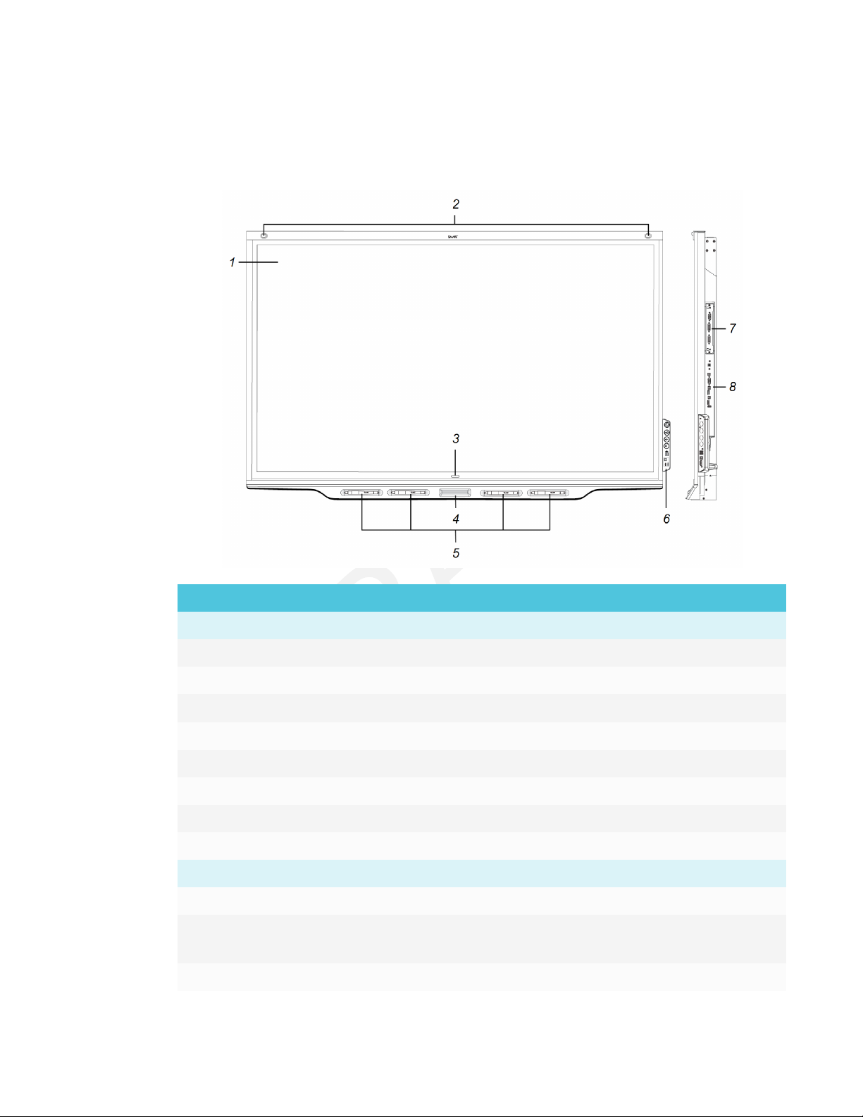
Components
The display consists of the following components:
No. Name More information
Pictured
1 Screen Page5
2 Presence detection sensor (×2) Page9
3 Home button Page5
4 Eraser Page7
5 Pen (×4) Page6
6 Convenience panel Page8
7 iQ appliance Page5
8 Connector panel Page27
Not pictured
9 AC power inlet, outlet and switch Page32
10 RS-232 connectors Page20
Page85
11 Speakers Page9
4 smarttech.com/kb/171164
CHAPTER 1
WELCOME
iQ appliance
The iQ appliance is installed in the accessory slot on the back of the SBID-7275, SBID-7286,
SBID-7275P and SBID-7286P models. Take advantage of iQ technology and access collaborative
tools.
CAUTION
The accessory slot’s maximum available power is 60 W. The slot is not a limited power source.
To reduce the risk of fire, make sure that accessories connecting to the slot satisfy the fire
enclosure requirements of IEC60950-1.
TIP
Use the Identifying your iQ appliance model wizard on the SMART support site to identify your
model of iQ appliance.
Screen
The following are the dimensions for the display:
Model Diagonal Width Height
SBID-7075 75" (1 90.5 cm) 65" (165.2cm) 38 5/8" ( 93 cm)
SBID-7086 86" (218.4 cm) 74 7/8" (190.3 cm) 42" (107 cm)
SBID-7275 75" (1 90.5 cm) 65" (165.2cm) 38 5/8" ( 93 cm)
SBID-7286 86" (218.4 cm) 74 7/8" (1 90.3 cm) 42" (10 7 cm)
SBID-7075P 75" (1 90.5 cm) 65" (165.2cm) 38 5/8" (93 cm)
SBID-7086P 86" (218.4 cm) 74 7/8" (190.3 cm) 42" (107 cm)
SBID-7275P 75" (190.5 cm) 65" (165.2 cm) 38 5/8" (93 cm)
SBID-7286P 86" (218.4 cm) 74 7/8" (1 90.3 cm) 42" (10 7 cm)
The display’s HyPrTouch™ (HybridPrecisionTouch) technology enables you to interact with
objects on the screen and write and draw in digital ink.
Home button
Tap the Home button to open the launcher. From the launcher, you can open the iQ appliance’s
apps as well as the settings.
5 smar ttech.com/kb/171164
CHAPTER 1
WELCOME
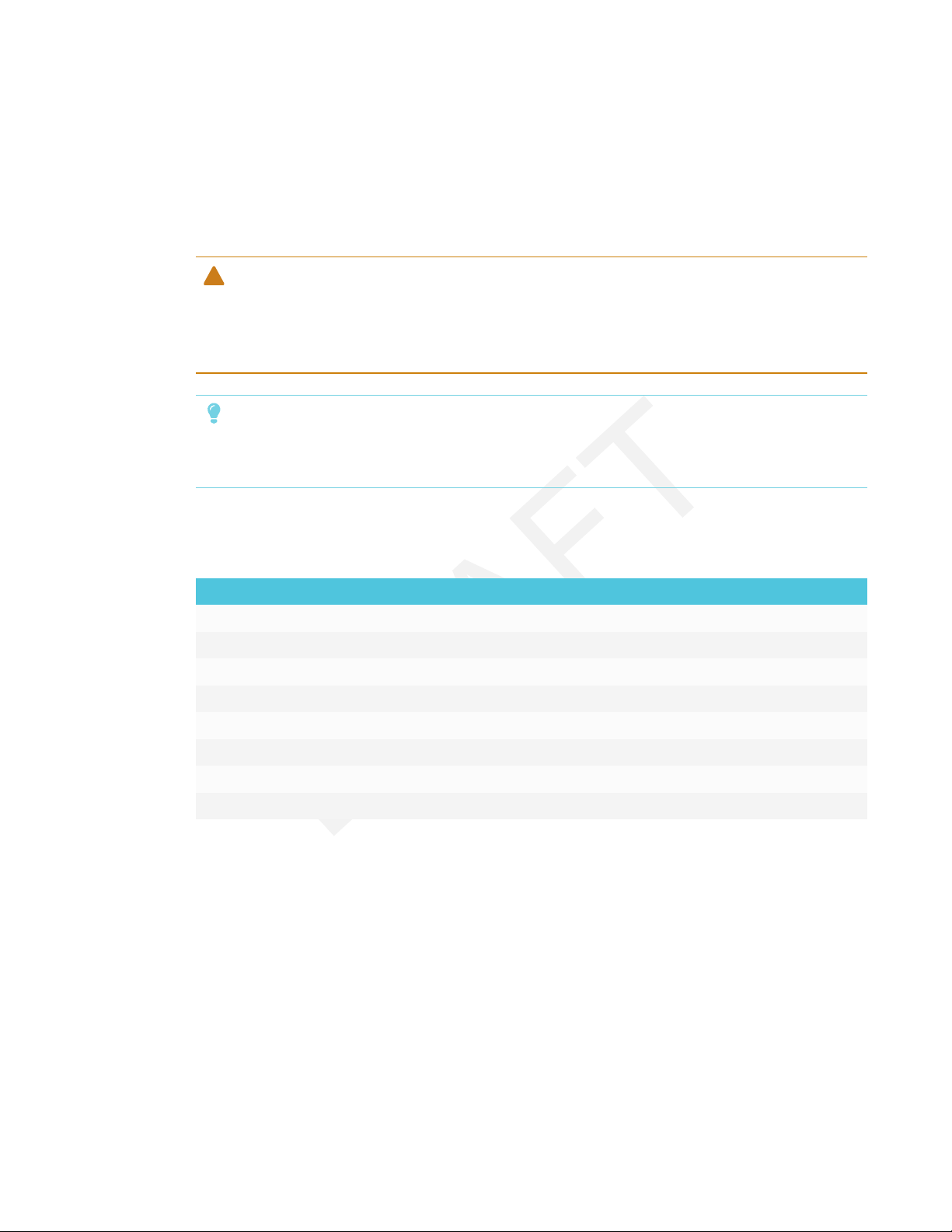
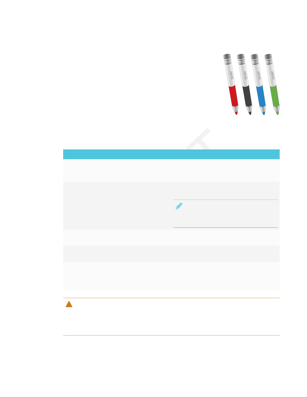
Pens
The display comes with black, red, blue and green pens. Each pen has
an attached eraser and an indicator light.
The display’s bottom frame includes magnetic holders for the pens.
Removing a pen from its holder activates it, and you can use the pen to
draw or erase digital ink. Replace the pen when you’re done using it to
charge it.
When you first turn on the display or pick up a pen from the magnetic holder, the pen’s light turns
on to indicate the pen’s status:
Light Pen status Action
Solid green The pen is charging slowly
and can be used for at least
two hours.
Solid amber The pen is charging quickly
and can be used for less
than two hours.
Solid red The pen needs to be
charged within 30 minutes.
Flashing red The pen needs to be
charged within 10 minutes.
Flashing green or
amber (while the
The pen’s firmware is
updating.
pen is in the
magnetic holder)
CAUTION
Pick up the pen and use it to write on the
display. Return the pen to the magnetic holder
when you’re done.
Use the pen for up to two hours. Return the pen
to the magnetic holder when done.
NOTE
It is normal for pens to be warm to the touch
when charging quickly.
Finish using the pen and return it to the
magnetic holder when done.
Return the pen to the magnetic holder as soon
as possible.
Wait for the light to stop flashing. This indicates
the pen’s firmware has completed updating.
When you return a pen to the magnetic holder, make sure it’s centered in its holder to keep it
from falling and being damaged. The pen’s light turns on to indicate that it’s properly positioned
in the holder.
6 smar ttech.com/kb/171164
CHAPTER 1
WELCOME
IMPORTANT
l Use only pens designed for SMARTBoard 7000 series interactive displays (see
smarttech.com/kb/171230).
l After you install the display and turn it on for the first time, place the pens in the holders for
at least five minutes. This pairs the pens with the display and charges them for testing
purposes.
l If you previously paired a pen with a SMART Board 7000 series interactive display, you must
pair it with another display to use it with that display. When you do this, the pen’s firmware
may be updated to align with the other display’s software.
l To fully charge the pens, keep them in the holders for at least four hours before users start
using the display.
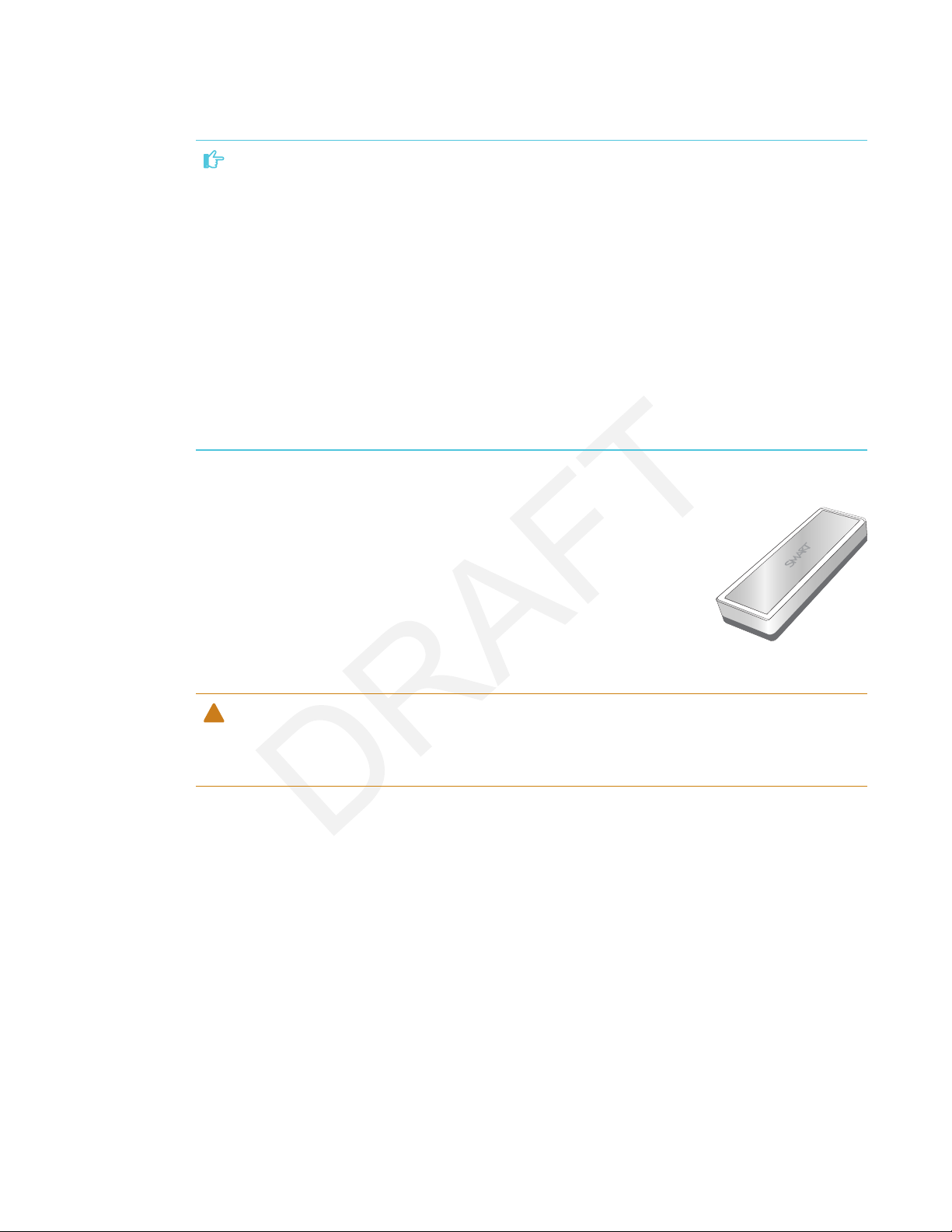
Eraser
In addition to the pens, the display includes an eraser, which you can use
when you want to erase a large area on the screen.
The display’s bottom frame includes a magnetic holder for the eraser.
Replace the eraser when you’re done with it.
CAUTION
When you return the eraser to the magnetic holder, make sure it’s centered in its holder to keep
it from falling and being damaged.
7 sm arttech.com/kb/171164
CHAPTER 1
WELCOME
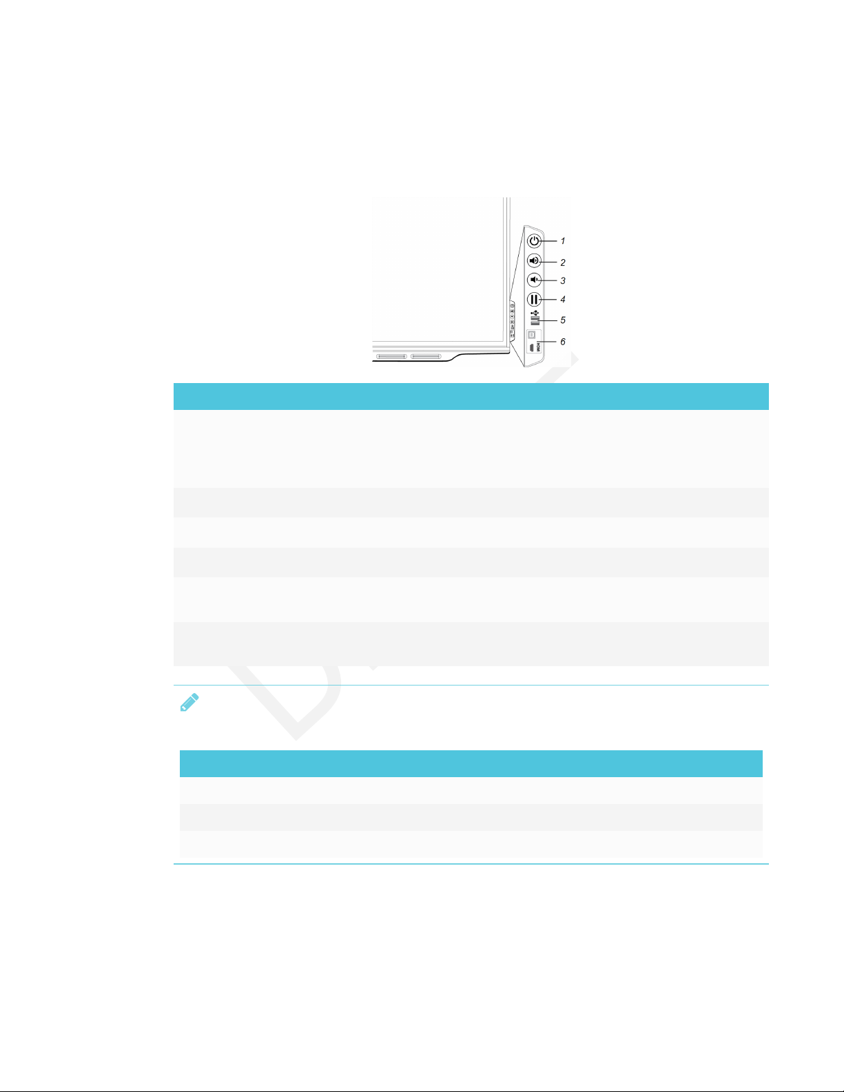
Convenience panel
The convenience panel contains buttons for turning the display on and off and controlling the
volume. It also includes connectors for USB peripherals and a computer or other input source.
No. Name Procedure
1 Power
Press to enter or exit Standby mode.
l
Press and hold for four seconds to turn off the display.
l
Press and hold for 10 seconds to reset the display.
l
2 Volume increase Press to increase the volume.
3 Volume decrease Press to decrease the volume.
4
Freeze
5 USB Type A
connector (×2)
6 HDMI 2 input
connectors
Press to freeze and unfreeze the screen.
Connect USB drives and other devices that you want to use
with the iQ appliance or a connected computer.
Connect a computer or other input source to use with the
display (see page23).
NOTE
The Power button indicates the display’s status:
Power button Display status
Off Not receiving power
Amber Standby mode
White Normal operating mode
8 smar ttech.com/kb/171164
CHAPTER 1
WELCOME
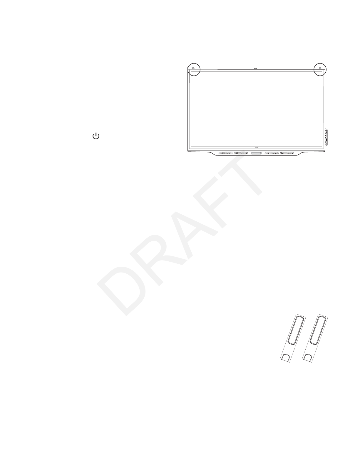
Presence detection sensors
The display has two presence detection
sensors on its top frame that can detect
people up to 16' (5 m) away when the
display is in Standby mode.
When the sensors detect people in the
room, the display is ready to turn on. To
turn on the display, press the Power
button or pick up a pen or eraser.
If the room is empty for a specified
period, the display returns to Standby
mode.
Internal speakers
The display includes two 10 W integrated speakers. You can also connect external speakers (see
Connecting external speakers on page25).
Related products
Related products for the display include the following:
l SBA-100 projection audio system
l SMART Audio 400 classroom amplification system
l USB extenders
SBA-100 projection audio system
Available for education models, the SBA-100 projection audio system consists
of two 14 W speakers and is intended for wall-mounted displays. You can
control volume using the display’s convenience panel or the digital volume
controls in a connected computer’s operating system.
For more information, see the SBA-100 projection audio system specifications
(smarttech.com/kb/171146).
9 smar ttech.com/kb/171164
CHAPTER 1
WELCOME
SMART Audio 400 classroom amplification system
Available for education models, the SMART Audio 400 classroom amplification
system provides high-quality audio amplification. The system comes with a
teacher microphone and optional student microphone. Multiple speaker
options are available, including wall- and ceiling-mounted speakers. The
amplifier receives audio signals from the microphones and translates them into
crystal-clear sound through the speakers.
For more information, see the SMART Audio 400 classroom amplification system specifications
(smarttech.com/kb/171137).
USB extenders
As noted in Connecting cables for room computers, guestlaptops and other input sources on
page23, the USB connection between the display and computer should be no longer than 16'
(5m). If you need to connect a computer that is more than 16' (5 m) from the display, use one of the
following USB extenders:
Extender Specifications
USB-XT smarttech.com/kb/119318
CAT5-XT-1100 smarttech.com/kb/170202
More information
In addition to this guide, SMART provides the following documents for the display:
Document Link
Quick reference smarttech.com/kb/171162
User’s guide smarttech.com/kb/171163
SMART Board 7000 series interactive display installation
instructions
SMART Board 7000 Pro series interactive display installation
instructions
SBID-7075 specifications smarttech.com/kb/171131
SBID-7086 specifications smarttech.com/kb/171132
smarttech.com/kb/171160
smarttech.com/kb/171221
SBID-7275 specifications smarttech.com/kb/171133
SBID-7286 specifications smarttech.com/kb/171134
SBID-7075P specifications smarttech.com/kb/171211
10 smarttech.com/kb/171164

CHAPTER 1
WELCOME
Document Link
SBID-7086P specifications smarttech.com/kb/171212
SBID-7275P specifications smarttech.com/kb/171213
SBID-7286P specifications smarttech.com/kb/171214
Comparison smarttech.com/kb/171161
These documents are available in the Support section of the SMART website
(smarttech.com/support). Scan the QR code on the cover of this guide to view the SMARTBoard
7000 series interactive display with iQ pages in the Support section.
11 smar ttech.com/kb/171164

Chapter 2
Transporting the display 13
Using transportation aides 14
Accommodating doorways, hallways and elevators 14
Dealing with cracked, chipped or shattered glass 15
Saving the original packaging 15
Installing the display on a wall 16
Choosing a location 16
Choosing a height 17
Mounting the display 18
Mounting multiple displays 20
Installing the display on a stand 20
SMART recommends that only trained installers install the display.
This chapter is for installers. Installers should read this information along with the installation
instructions included with the display before they install the display.
WARNING
Improper installation of the display can result in injury and product damage.
Transporting the display
After your organization receives the display, you need to transport it to the place where you plan
to install it.
On occasion, you might also need to move the display to another location after initially installingit.
IMPORTANT
l Transport the display at your own risk. SMART cannot accept liability for damages or injury
that occur during the display’s transportation.
13 smarttech.com/kb/171164

CHAPTER 2
INSTALLING THE DISPLAY
l When transporting the display, do the following:
o
Follow local safety regulations and standards.
o
Keep the display in its original packaging.
o
Move the display so that its top frame faces up.
o
Have at least two people move the display.
Using transportation aides
You can use the following aides to transport the display:
l Cart
l Furniture dolly
l Mechanical lift
NOTE
The display features eyebolt mounting holes for use with mechanical
lifts. Refer to the installation instructions for information on using a
mechanical lift.
Accommodating doorways, hallways and elevators
In some situations, you might need to remove the display from its packaging to move it through
narrow doorways or hallways or on to an elevator. In these situations, SMART recommends that
you keep the foam pieces on the bottom corners of the display. These foam pieces protect the
display if you need to set it down during transport.
You might also need to rotate the display so that its top frame faces to the side. You can do this
during transportation, but when you install the display, it must be in landscape orientation (with the
top frame facing up).
14 sma rttech.com/kb/171164
CHAPTER 2
INSTALLING THE DISPLAY
Dealing with cracked, chipped or shattered glass
The display contains safety-tempered glass. Although this glass is heat-strengthened to help
withstand impacts, the glass can crack, chip or shatter if struck with enough force. (Safety glass is
designed to break into small pieces rather than sharp shards if it is broken.) Temperature changes
can cause a minor crack or chip to become worse, possibly causing the glass to shatter. See
Shattered glass on an interactive display for information about conditions that can cause the
display’s glass to shatter even when it’s not in use.
If the display’s glass is cracked or chipped, have it professionally inspected and repaired at a
SMART authorized repair center. If the display’s glass shatters, carefully clean up the area and have
the display repaired or replaced.
CAUTION
For safety and to prevent further damage, do not continue to install or use the display if its glass
is cracked, chipped or shattered.
Saving the original packaging
Save the original packaging to repack the display with as much of the original packaging as
possible in case you need to transport the display again after you initially install it. This packaging
was designed to provide the best possible protection against shock and vibration.
CAUTION
Transport the display only in the original packaging or replacement packaging purchased from
your authorized SMART reseller. Transporting the display without correct packaging can lead to
product damage and voids the warranty.
NOTE
If the original packaging isn’t available, you can purchase the same packaging directly from your
authorized SMART reseller (smarttech.com/where).
15 smarttech.com/kb/171164
CHAPTER 2
INSTALLING THE DISPLAY
Installing the display on a wall
Typically, you install the display on a wall in a classroom or meeting space.
Choosing a location
A display is typically installed at the room’s focal point, such as at the front of a classroom or
meeting room.
Selecting an appropriate location for the display is crucial for ensuring the best possible
experience with the product. Consider the following factors as you choose a location:
Factor Considerations
Room setup
The location allows users, including those in wheelchairs, to access the
l
display.
The location is clearly visible to all users in the room. For more
l
information, see Recommended viewing distances and viewing angles
for SMARTBoard interactive displays.
The display will not be installed where it could be hit by a door or gate.
l
There are no nearby shelving units, desks or other furniture that has
l
doors or drawers that could hit the display.
Wall support The wall can support the weight of the display and mounting equipment.
Refer to the model’s specifications for the weight of the display (see
More information on page10).
Power and other
connections
The location is close to the following:
l
o
A power outlet
o
A network outlet (if you plan to use a wired network connection)
o
A room computer (if you plan to connect a room computer)
o
Speakers and other devices that you want to connect to the display
The location is not where the mains power supply enters the building.
l
Lighting The location is not near bright light sources, such as windows or strong
overhead lighting. Infrared (IR) lighting can cause issues with presence
detection.
Acoustics The location has good acoustics.
TIP
Stand in different parts of the room and count to ten loudly. If you hear
anything other than your own voice (such as a rattle, buzzing from
elsewhere in the room or echoes), the room may require some
modifications to improve the acoustics. Work with an audio specialist
to improve the acoustics.
16 smarttech.com/kb/171164
CHAPTER 2
INSTALLING THE DISPLAY
Factor Considerations
Environment and
ventilation
The location meets the environmental requirements in the display’s
l
specifications (see More information on page10).
The display isn’t subjected to strong vibrations or dust.
l
There is adequate ventilation or air conditioning around the display so
l
that heat can flow away from the unit and the mounting equipment.
If you’re planning to install the display in a recessed area, there is at least
l
4" (10 cm) of space between the display and the recessed walls to
enable ventilation and cooling.
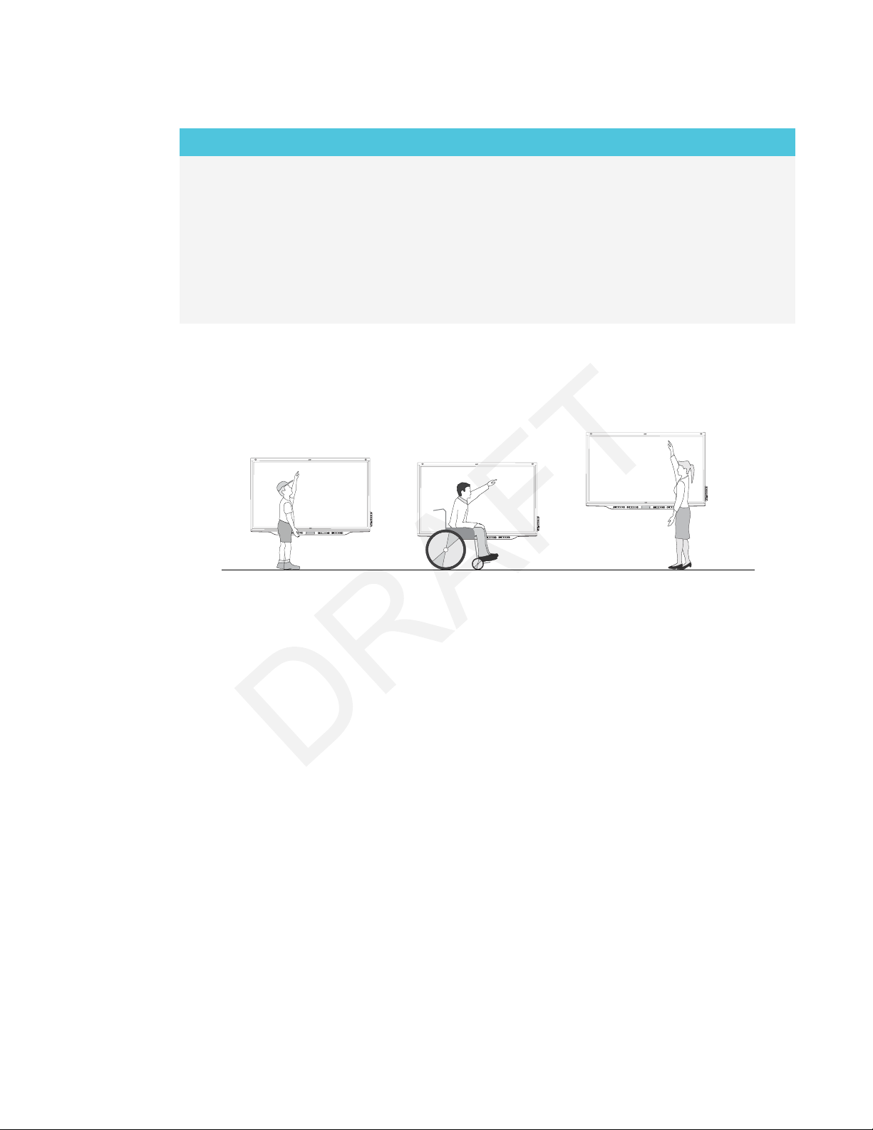
Choosing a height
Consider the general height of the user community when you choose the height for the display.
SMART recommends that you mount the display so that its top is 6'5" (1.9m) from the floor.
17 smar ttech.com/kb/171164
CHAPTER 2
INSTALLING THE DISPLAY
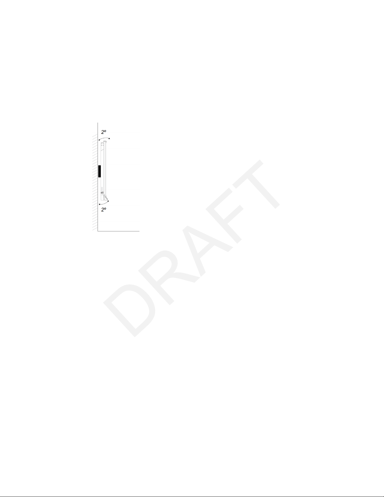
Mounting the display
Mount the display following the included installation instructions. In addition, consider the
following:
l Mount the display vertically (90° relative to the floor plus or minus 2° for tolerance) and in
landscape orientation. SMART doesn’t support mounting the display at other angles or in
portrait orientation.
l Use a standard VESA mounting plate.
18 smarttech.com/kb/171164
CHAPTER 2
INSTALLING THE DISPLAY
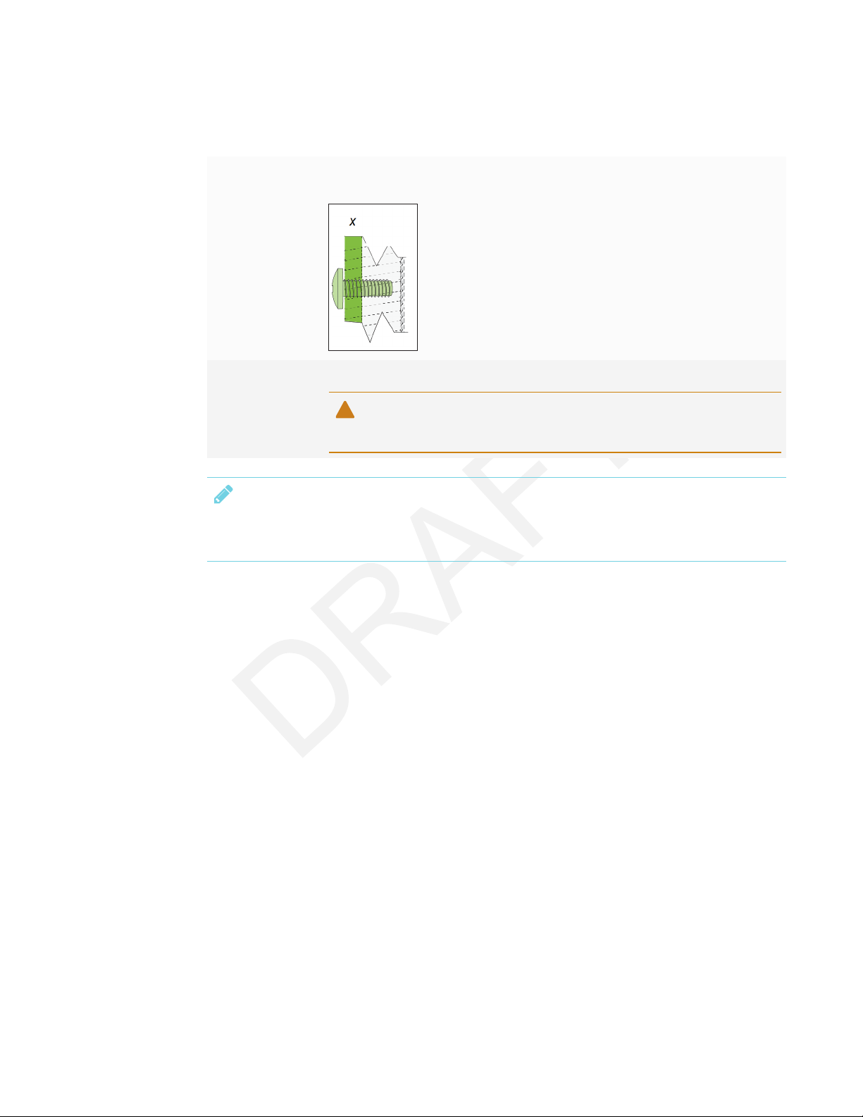
l Use M8 screws to fasten the wall bracket.
Screw length 12 mm + x mm < M8 < 45 mm + xmm
where x is the combined thickness of the wall bracket and washer
Fasten force
97.36–177.01 in-lb. (11–20 N·m)
CAUTION
Do not over-tighten the screws.
NOTE
SMART recommends M8 × 30 mm mounting screws for standard installations where the
total wall mount bracket and washer thickness is less than 7 mm.
l Because the receptacles might not be easily accessible after you mount the display, consider
connecting cables for power, room computer and other devices while the display is still in its
packaging (see Chapter 3: Connecting power and devices on page21).
19 smarttech.com/kb/171164
CHAPTER 2
INSTALLING THE DISPLAY
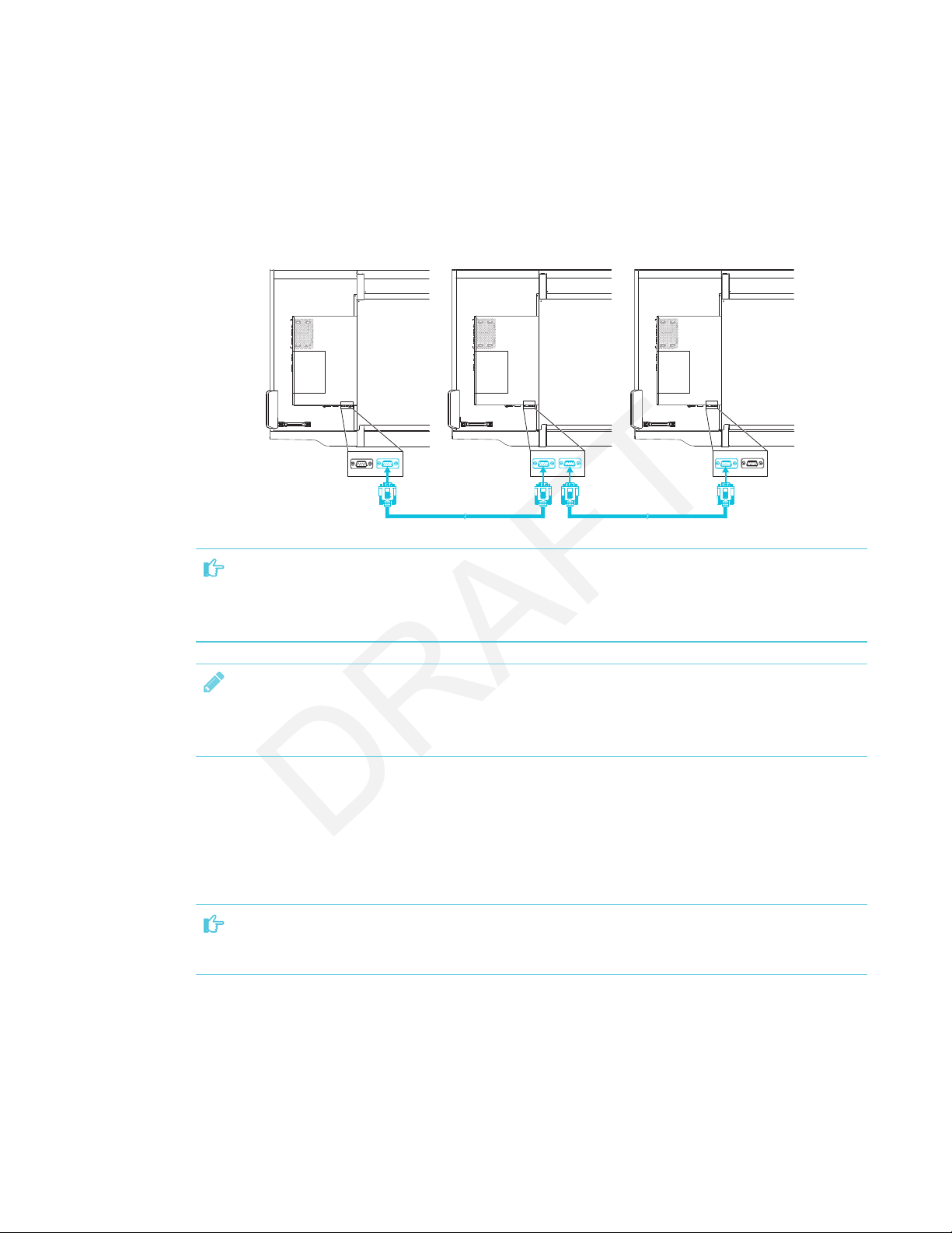
Mounting multiple displays
If you mount multiple displays side by side, you can connect a RS-232 cable from the rightmost
display’s RS-232OUT connector to the next rightmost display’s RS-232IN connector, and so forth,
to turn on, turn off and otherwise operate all of the displays from the right-most display’s
convenience panel.
IMPORTANT
Use only standard RS-232 cables. Do not use a null modem cables. Null modem cables typically
have ends of the same type.
NOTE
For more information on using RS-232 cables for remote management, see Appendix B:
Remotely managing the display on page85.
Installing the display on a stand
If you want to move the display from place to place or if it’s not possible to install the display on a
wall, you can install it on a stand.
IMPORTANT
If you install the display on a stand, do not move the stand while the display is on.
For information on selecting and using a third-party stand, see SMART installation standards
(smarttech.com/kb/171035).
20 smar ttech.com/kb/171164

Chapter 3
Connecting power 22
Connecting to a network 22
Connecting cables for room computers, guestlaptops and other input sources 23
Using recommend cables 24
Connecting to the connector panel 24
Connecting to the convenience panel 25
Viewing a connected computer or other device’s input 25
Connecting external speakers 25
Connecting other devices 26
Connector reference 27
Display connectorpanel 27
Display convenience panel 28
iQ appliance 28
Other connectors 29
Connect the display to power after you install it but before you turn it on for the first time and
configure the iQ appliance. You can also connect cables for room computers, guest laptops or
other input sources as well as for speakers and other devices.
By installing cables in advance, you make use of connectors that might not be accessible after the
display is wall-mounted. You can then run the cables across floors or behind walls as needed.
WARNING
Ensure that any cables that cross the floor to the display are properly bundled and marked to
avoid a trip hazard.
21 smarttech.com/kb/171164

CHAPTER 3
CONNECTING POWER AND DEVICES
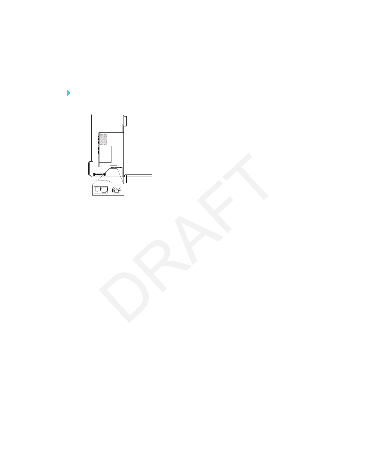
Connecting power
Connect the supplied power cable from the AC power inlet on the
bottom of the display to a power outlet.
NOTE
Refer to the display’s specifications for power requirements and power consumption information
(see More information on page10).
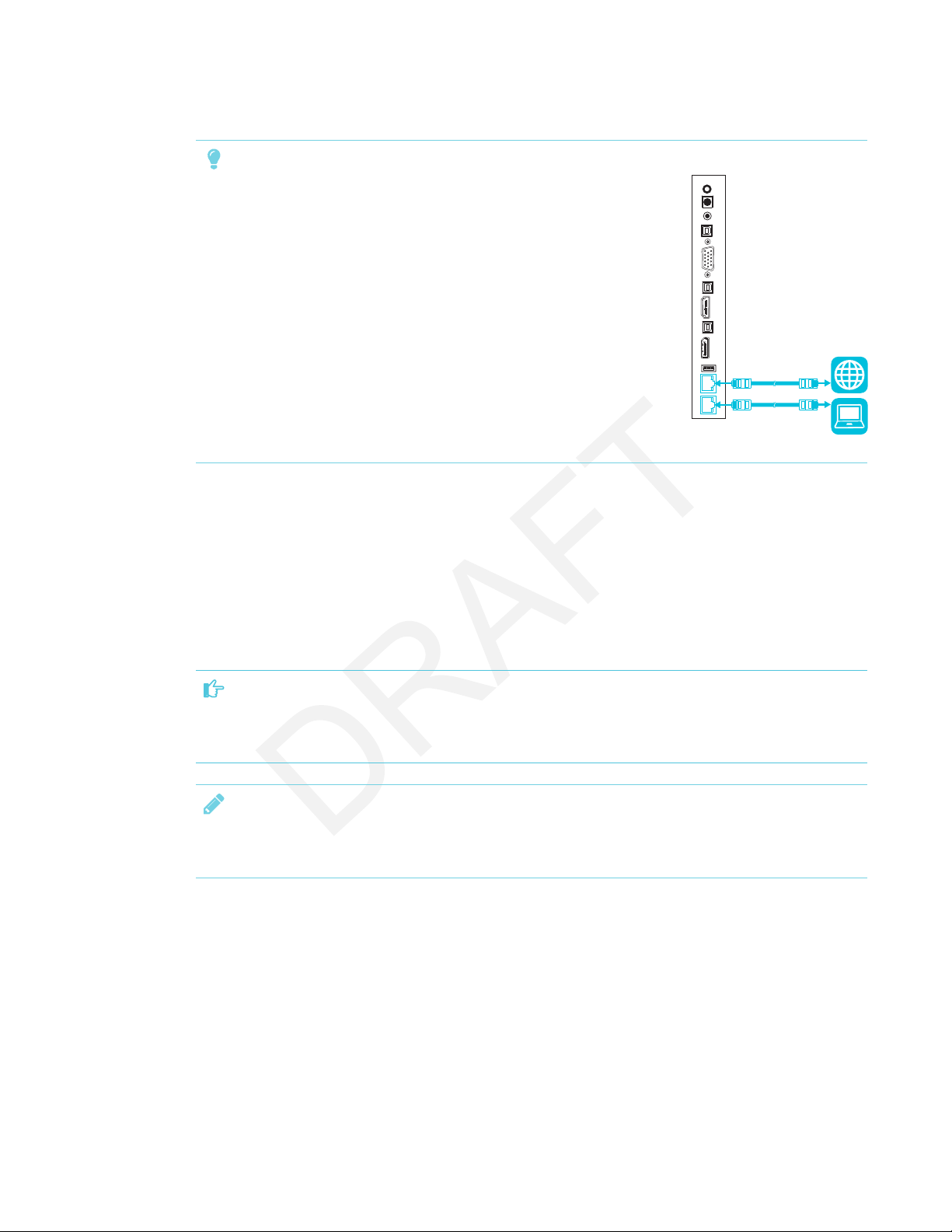
Connecting to a network
The display requires a network connection for downloading software
and firmware updates, and a number of the iQ appliance’s apps require
a network connection as well. You can connect to a network using a
Wi-Fi connection or one of the RJ45 jacks on the display (pictured). For
more information about the display’s network connection and
configuration, see Connecting to a network on page33.
IMPORTANT
Do not use the RJ45 jack on the iQ appliance to connect to a network.
22 smarttech.com/kb/171164
CHAPTER 3
CONNECTING POWER AND DEVICES
TIP
If you’re using one of the display’s RJ45 jacks to connect to a network,
you can connect the other RJ45 jack to a computer to provide
network access for the computer. This is particularly useful if there is
only one wired network connection in the room.
Connecting cables for room computers,
guestlaptops and other input sources
You can connect cables to the display so that users can connect and use room computers, guest
laptops or other devices, such as Blu-ray™ disc players.
IMPORTANT
Do not connect computers or other devices to the iQ appliance. SMARTBoard 7000 series
interactive displays do not support the use of this connector.
NOTE
For information about configuring connected computers, see Chapter 5: Configuring connected
computers on page43.
23 smarttech.com/kb/171164

CHAPTER 3
CONNECTING POWER AND DEVICES
Using recommend cables
SMART recommends the following varieties of cable:
Cable type Maximum length Recommendation
HDMI 23' (7 m)
1
Use only certified HDMI cables that have been
tested to support the performance standard you
require.
DisplayPort 23' (7 m) Use DisplayPort 1.2 compliant or better cables.
VGA [N/A] Use VGA cables with all pins in their connectors fully
populated and wired.
Stereo 3.5 mm 20' (6 m) [N/A]
USB 16' (5 m) Use a USB extender if the distance between the
computer and the display is greater than 16' (5 m).
For more information, see USB extenders on
page10.
Using cables that exceed these maximum lengths may produce unexpected results, degraded
picture quality or degraded USB connectivity.
Connecting to the connector panel
The connector panel includes three sets of computer
connectors:
l VGA: This set of connectors can accommodate a
USBcable for touch control, a VGA cable for video
and a stereo 3.5 mm cable for audio.
l HDMI 1: This set of connectors can accommodate
a USB cable for touch control and an HDMI cable
for video and audio. (This input supports HDMI2.0.)
l DisplayPort: This set of connectors can
accommodate a USBcable for touch control and a
DisplayPort cable for video and audio.
1
The performance of cables longer than 23' (7 m) is highlydependent on the cable’s quality.
24 smarttech.com/kb/171164

CHAPTER 3
CONNECTING POWER AND DEVICES
Connecting to the convenience panel
In addition to the three sets of computer connectors on
the connector panel, there is one set of computer
connectors on the convenience panel:
HDMI 2: This set of connectors can accommodate
a USBcable for touch control and an HDMI cable for
video and audio. (This input supports HDMI1.4.)
Viewing a connected computer or other device’s input
Users can use the Input app to view the computer or other device’s input on the display.
For information about the Input app, see the SMARTBoard 7000 series interactive display user’s
guide (smarttech.com/kb/171163).
Connecting external speakers
The display includes two 10 W speakers, which are designed to provide sound at the front of a
room. You might want to connect the SBA-100 projection audio system (see SBA-100 projection
audio system on page9) or third-party external active speakers if you’re providing sound in a
larger space.
You can connect external speakers to the display using the stereo
3.5mm out connector (pictured). Alternatively, you can connect
external speakers directly to a room computer.
25 smarttech.com/kb/171164

CHAPTER 3
CONNECTING POWER AND DEVICES
In addition to the stereo 3.5 mm out connector, the display provides a
Sony/Philips Digital Interface (S/PDIF) out connector. S/PDIF is a digital
audio transmission medium. You need an audio receiver that supports
S/PDIF to decode this connection to analog for use with external
speakers.
Connecting other devices
In addition to external speakers, you can connect the following devices to the display:
Device type Details
Microphones Microphones can improve the audio experience in a classroom or lecture
hall. SMART offers a classroom audio system that includes microphones (see
SMART Audio 400 classroom amplification system on page10).
Room control
systems
Although SMART doesn’t offer room control equipment, the display supports
RS-232 communication for remote management (see Appendix B: Remotely
managing the display on page85).
26 smarttech.com/kb/171164

CHAPTER 3
CONNECTING POWER AND DEVICES
Connector reference
Display connectorpanel
The following diagram and table present the connectors on the display’s connector panel:
No. Connector Connects to Notes
1 Stereo 3.5 mm out External speakers See page25.
2 S/PDIF out Digital audio output See page25.
3 Stereo 3.5 mm in VGA input (audio) See page23.
4 USB Type-B VGA input (touch) See page23.
5 VGA in VGA input (video) See page23.
6 USB Type-B HDMI 1 input (touch) See page23.
7 HDMI 2.0 in HDMI 1 input
(videoandaudio)
8 USB Type-B DisplayPort input (touch) See page23.
9 DisplayPort in DisplayPort input
(videoandaudio)
10 USB Type-A [N/A] This connector is a service port.
11 RJ45 (×2) Network See page22.
See page23.
See page23.
27 smarttech.com/kb/171164

CHAPTER 3
CONNECTING POWER AND DEVICES
Display convenience panel
The following diagram and table present the connectors on the display’s convenience panel:
No. Connector Connects to Notes
1 USB Type-A (×2) Supported peripherals [N/A]
2 USB Type-B HDMI 2 input (touch) See page23.
3 HDMI 1.4 in HDMI 2 input
(videoandaudio)
See page23.
iQ appliance
The following diagram and table present the connectors on the iQ appliance:
AM30
AM40
No. Connector Connects to Notes
1 RJ45 Network Do not use this connector. Use
the connectors on the display
instead. See page22.
28 smarttech.com/kb/171164

CHAPTER 3
CONNECTING POWER AND DEVICES
No. Connector Connects to Notes
2 USB Type-A (×2) Supported peripherals [N/A]
3 HDMIout N/A This connector is not supported.
4 USB Type-B OPS/HDMI input (touch) Do not use this connector. Use
the connectors on the display
instead. See page23.
5 HDMI in OPS/HDMI input
(videoandaudio)
Do not use this connector. Use
the connectors on the display
instead. See page23.
6 USBType-B [N/A] This connector is a service port.
7 Micro SD [N/A] This connector is a service port.
8 LED [N/A] LED lights green when the iQ
appliance is inserted in the
accessory slot and turned on.
NOTE
Older models of the iQ appliance (AM30)don’t have all the connectors.
Other connectors
There are additional connectors on the bottom of the display (see Mounting multiple displays on
page20 and Appendix B: Remotely managing the display on page85).
29 smarttech.com/kb/171164


Chapter 4
Turning on the display for the first time 32
Connecting to a network 33
Configuring the display’s network connection 33
Configuring the network 33
Connecting the display to a network 36
Evaluating the impact of Screen Share on your network data usage 38
Updating system software 39
Applying an automatic system software update manually 39
Updating system software manually 40
Switching to the Beta channel 40
Before switching to the Beta channel 40
Switching between the Beta and Stable channels 40
Getting support and sending feedback 41
Adding or removing apps from the launcher 42
Enabling the Whiteboard Library 42
After you have mounted the display and connected power and devices, you can start it for the first
time and configure the apps as described in this chapter.
31 smarttech.com/kb/171164
CHAPTER 4
CONFIGURING THE DISPLAY
Turning on the display for the first time
Turn on the display after mounting it and connecting power and devices.
To turn on the display for the first time
1. Flick the switch beside the AC power inlet to the ON(I) position.
2. Select your preferred language, and then tap Next.
3. Select your country, and then tap Next.
4. Name the display, and then tap Next.
5. Set the date and time, and then tap Next.
6. If the display isn’t using a wired network connection, select a wireless network, and then tap
Next.
7. Select the list of applications that will appear in the launcher, and then tap Next. For more
information about the apps, see the SMARTBoard 7000 series interactive displays user’s
guide (smarttech.com/kb/171163)
8. Tap Finish.
The Welcome screen appears.
32 smarttech.com/kb/171164

CHAPTER 4
CONFIGURING THE DISPLAY
Connecting to a network
You can connect the display to a network using either Wi-Fi or an Ethernet connection. Before you
do so, your organization’s network administrators need to configure the network for the display.
Configuring the display’s network connection
IMPORTANT
Configuring the network properly allows the display to download important iQ system software
and feature updates automatically.
Network administrators need to configure the network so users can use the Screen Share app,
update the system software automatically over the air and enable the display to set the date and
time automatically.
Configuring the network
Network administrators need to configure the network so users can update the display’s firmware
and system software automatically over the air and to allow apps to function properly.
33 smarttech.com/kb/171164

CHAPTER 4
CONFIGURING THE DISPLAY
To configure the network
Add thefollowing URLs to the network whitelist.
URL Feature
https://ws.kappboard.com
Automatic iQ system software update
NOTE
Block access to https://ws.kappboard.com to
prevent automatic iQ system software updates
https://*.mixpanel.com iQ system software
*.hockeyapp.net iQ system software
https://*.smarttech-prod.com SMARTNotebook® Player
http://*.loggly.com SMARTNotebook Player
http://*.smarttech.com iQ system software, Workspaces, app,
Activities app, SMARTNotebook Player
https://*.smarttech.com SMARTNotebook Player
https://www.fabric.io/ SMARTNotebook Player
https://*.classlab.com Workspaces app, Activities app
https://www.firebase.com/test.html Workspaces app, Activities app
https://*.smartamp.com Workspaces app, Activities app
https://*.google.com Activities app
http://*.google-analytics.com Activities app
https://www.gstatic.com Activities app
https://*.firebaseio.com Activities app
https://*.cloudfront.com Activities app
https://content.googleapis.com Workspaces app
https://gstatic.com Workspaces app
https://*.youtube.com Workspaces app, SMARTNotebook
Player
https://api.datamarket.azure.com Workspaces app
https://updates.airsquirrels.com Screen Share app
34 smarttech.com/kb/171164

CHAPTER 4
CONFIGURING THE DISPLAY
To allow mobile devices and computers to use AirPlay and Google Cast to use the Screen Share
app
1. Open the required TCP/UDP ports:
Protocol Port range Feature
TCP 80 Outbound http
UDP 123 Network Time Protocol
TCP 3689 iTunes music sharing
TCP 5000 Audio streaming
TCP 5353 mDNS
UDP 5353 mDNS
TCP 7000 Picture sharing
TCP 7001 Video streaming
UDP 7010 Display mirroring
UDP 7011 Display mirroring
TCP 7100 Display mirroring
TCP 47000 Audio negotiation
TCP 49152–65535 Dynamic ports
UDP 49152–65535 Dynamic ports
TCP 49228 Google Cast
TCP 50259 Google Cast
UDP 54780 Google Cast
UDP 62572 Google Cast
2. Configure the network to allow Bonjour and mDNS (multicast).
3. Configure the network to allow Network Time Protocol (NTP) requests to Internet time servers.
NOTE
Using a 5 GHz wireless network connection may provide a better experience with the
Screen Share app.
35 smarttech.com/kb/171164

CHAPTER 4
CONFIGURING THE DISPLAY
To allow SMARTNotebook Player to connect to the display
NOTE
The network may have been configured to allow Network Time Protocol in To allow mobile
devices and computers to use AirPlay and Google Cast to use the Screen Share app.
Configure the network to allow Network Time Protocol (NTP) requests to Internet time servers
Connecting the display to a network
The display can connect to a network using either Wi-Fi or an Ethernet connection. Network
administrators can also add a browser proxy or install a certificate.
To connect to a Wi-Fi network
1. If an Ethernet cable is connected to the display, disconnect it.
Tap the Home button on the screen.
2.
The launcher appears.
Tap Settings .
3.
The Settings window appears.
4. Tap Wi-Fi.
NOTE
Ensure Wi-Fi is turned On.
5. Select a wireless network.
If the Wi-Fi network is not password protected, the display connects to the network.
6. If the network requires a password, enter the Wi-Fi password and tap Connect.
OR
If the network requires a user name and password, enter the user name and Wi-Fi password
and tap Connect.
TIP
Use the crosshairs to move the on-screen keyboard.
36 smarttech.com/kb/171164
CHAPTER 4
CONFIGURING THE DISPLAY
To connect to an Ethernet network
Connect an Ethernet cable to the RJ45 receptacle on the display.
NOTE
The network must provide network settings via DHCP. If you require a static IP, use DHCP
reservation on your router.
To configure a proxy
Tap the Home button on the screen.
1.
The launcher appears.
Tap Settings .
2.
The Settings window appears.
3. Tap Wi-Fi.
4. Tap and hold the network to which you’re adding a proxy.
A dialog box appears.
5. Tap Modify network.
6. Select Show advanced options.
7. In the Proxy box, select Manual.
8. Enter the information in the Proxy hostname, Proxy port and Bypass proxy boxes.
9. Tap Save.
To install a certificate
NOTE
Certificates must be PFX format.
1. Copy a PFX format certificate to a USB drive.
Tap the Home button on the screen.
2.
The launcher appears.
Tap Settings .
3.
The Settings window appears.
37 smarttech.com/kb/171164

CHAPTER 4
CONFIGURING THE DISPLAY
4. Tap Wi-Fi > … > Advanced > Install Certificates.
The USBDrive window appears.
5. Tap USB Drive.
6. Select a certificate to install.
7. If required, enter a password to extract the certificate.
8. Optionally, enter a name for the certificate in the Certificate name box and reason for
certificate use in the Credential use box. Tap OK.
A window appears requesting that a lock screen PIN, pattern or password be set before using
the certificate.
9. Tap OK.
10. Select a pattern, PIN or password method. Tap OK.
IMPORTANT
Make note of the pattern, PIN or password. The pattern, PIN or password may be required to
install future certificates.
If the pattern, PIN or password is forgotten, a factory reset is required before installing more
certificates.
The iQ system software confirms the certificate was installed.
Evaluating the impact of Screen Share on your network data usage
When you connect your device or computer to the display using Screen Share, the screen sharing
protocol compresses the image from your device or computer. The protocol may transmit only
areas of the screen that change. This can make it difficult to estimate the impact of Screen Share
on a network where many users would like to screen share simultaneously.
For example, in a school where 30 teachers are using Screen Share simultaneously, 10% of
teachers might be streaming video while 90% might be sharing static content with occasional
updates. In such an instance, you could expect to see an additional 5 Mbps in network traffic. Use
the following table to help estimate the impact of wireless Screen Share on your network.
Content being shared Data rate transmission
Static content with minor screen movement 20 kbps
Static content with periodic scrolling or
refreshes
38 smarttech.com/kb/171164
Spikes briefly to 500–600 kbps, returns to 20
kbps

CHAPTER 4
CONFIGURING THE DISPLAY
Content being shared Data rate transmission
Gaming or streaming video with major screen
changes
700 kb/sec–1.2 Mbps
Updating system software
When the display is connected to the Internet, it updates the system software and the firmware
automatically.
When an update to the system software or firmware is available, the display downloads the update
in the background then waits for four hours of inactivity. When that happens, the display shows a
two-minute countdown before beginning the update. The countdown can be interrupted at any
time. The update begins when the countdown finishes. The display shows a blank screen for four
minutes. When the update is complete, the display shows the Whiteboard and any content that
was on Whiteboard before the update.
NOTE
You can configure your organization’s network to allow or prevent automatic system software
and firmware updates (see Configuring the display’s network connection on page33).
Applying an automatic system software update manually
If the display has downloaded the system software update but hasn’t yet applied the update, you
can start the update process manually from Settings.
To apply an automatic system software update manually
Tap the Home button on the screen.
1.
The launcher appears.
Tap Settings .
2.
The Settings window appears.
3. Scroll to Auto Update.
4. Under Check for Updates Now, tap Apply Update Now.
The display turns off and then turns back on. The display then applies the update.
If there is an update for the pen firmware, the pen’s indicator light will flash green or amber.
Leave the pen in the tray until the pen’s light is a solid color.
39 smarttech.com/kb/171164

CHAPTER 4
CONFIGURING THE DISPLAY
Updating system software manually
You can download system software updates at smarttech.com/downloads and update your display
using a USB drive.
Switching to the Beta channel
The Beta channel is meant for advanced users who are comfortable using pre-release software.
System software releases in the Beta channel contain new features that are still in development.
Sign up to receive Beta channel announcements at smarttech.com/SMARTBetaProgram.
IMPORTANT
l You may encounter bugs or other unexpected behavior in pre-release software.
l Features previewed in the Beta channel may never appear in a Stable channel release.
l There may be frequent updates to the display’s system software.
l The user interface may change significantly as features develop.
l If you switch to the Beta channel and want to return to the Stable channel, you must perform
a factory reset that erases all of the display’s settings.
Before switching to the Beta channel
Before switching to the Beta channel, back up important Whiteboard content using the
SMARTkapp® app. See the SMARTBoard 7000 series interactive displays user’s guide
(smarttech.com/kb/171163).
Switching between the Beta and Stable channels
To switch to the Beta channel
Tap the Home button on the screen.
1.
The launcher appears.
Tap Settings .
2.
The Settings window appears.
3. Tap Auto Update.
40 smarttech.com/kb/171164

CHAPTER 4
CONFIGURING THE DISPLAY
4. Tap Update Channel, and then select Beta Channel.
A dialog box appears asking you to confirm the switch to the beta system software releases.
The display checks for a Beta system software update.
To switch to the Stable channel
Tap the Home button on the screen.
1.
The launcher appears.
Tap Settings .
2.
The Settings window appears.
3. Tap Auto Update.
4. Tap Update Channel, and then select Stable Channel.
A dialog box appears asking you to confirm the switch to the Stable channel system software
releases.
The display checks for a Stable channel system software update.
5. Tap Ready to apply update.
Getting support and sending feedback
SMART Support will not be able to help you resolve problems you may encounter in Beta channel
releases.
SMART appreciates your willingness to use Beta channel releases and values all types of
feedback.
l Report issues with Beta channel releases at smarttech.uservoice.com.
l Provide feedback to SMART about new features at smarttech.uservoice.com.
l Suggest new features to SMART at smarttech.uservoice.com.
41 sma rttech.com/kb/171164

CHAPTER 4
CONFIGURING THE DISPLAY
Adding or removing apps from the launcher
You can add or remove apps from the launcher.
To add or remove apps from the launcher
Tap the Home button on the screen.
1.
The launcher appears.
Tap Settings .
2.
The Settings window appears.
3. Tap Launcher.
4. Select the apps you want to include in the launcher.
OR
Clear the check boxes for apps you want to remove from the launcher.
Enabling the Whiteboard Library
The display saves Whiteboard sessions to the Library.
The Library is disabled on some displays and must be enabled if you want to save Whiteboard
sessions or continue previous sessions.
To enable the Library
Tap the Home button on the screen.
1.
The launcher appears.
Tap Settings .
2.
The Settings window appears.
Tap Applications, and then tap Whiteboard .
3.
4. Switch the Library option ON.
42 smarttech.com/kb/171164

Chapter 5
Installing SMART software on connected computers 43
Installing SMART Learning Suite 43
Installing SMART MeetingPro software 44
Setting connected computers’ resolutions and refresh rates 44
Install SMARTsoftware and set the resolution and refresh rate on any computers you connect to
the display.
NOTE
For information about connecting computers, see Connecting cables for room computers,
guestlaptops and other input sources on page23.
Installing SMART software on connected computers
The display comes with either SMARTLearning Suite or SMARTMeetingPro® software.
Installing SMART Learning Suite
The SBID-7075, SBID-7086, SBID-7275 and SBID-7286 models come with one license of SMART
LearningSuite. You can download SMART LearningSuite from smarttech.com/downloads and
install it on a room computer.
You can purchase additional licenses of SMARTLearning Suite to install on other computers.
Contact your authorized SMART reseller (smarttech.com/where) for more information.
IMPORTANT
Make sure a computer meets the minimum requirements in the SMARTNotebook software
release notes before you install SMART Learning Suite.
43 smarttech.com/kb/171164

CHAPTER 5
CONFIGURING CONNECTED COMPUTERS
Installing SMART MeetingPro software
The SBID-7075P, SBID-7086P, SBID-7275P and SBID-7286P models come with one room license
and ten personal licenses of SMARTMeetingPro software. You can download
SMARTMeetingPro software from smarttech.com/downloads and install the room license on a
room computer and the personal licenses on up to then users’ laptops.
You can purchase additional licenses of SMARTMeetingPro software to install on other
computers. Contact your authorized SMART reseller (smarttech.com/where) for more information.
IMPORTANT
Make sure a computer meets the minimum requirements in the SMARTMeetingPro software
release notes before you install SMARTMeetingPro software.
Setting connected computers’ resolutions and refresh rates
The following table presents the recommend resolutions and refresh rates for the display’s input
sources:
Input source Resolution Refresh rate
HDMI 1 3840×2160 60Hz
HDMI 2 1920×1080 60Hz
DisplayPort 1920×1080 60Hz
VGA 1920×1080 60Hz
If possible, set any connected computers to these resolutions and refresh rates. See the
connected computers’ operating system documentation for instructions.
44 smarttech.com/kb/171164

Chapter 6
Checking the display installation 45
Cleaning the display 45
Maintaining ventilation 46
Preventing condensation 46
Replacing the pens and eraser 47
Turning the display off and back on 47
Resetting the display 48
Removing and transporting the display 48
With proper maintenance, the display will provide years of use.
Checking the display installation
Inspect the display installation frequently to ensure that it remains securely installed.
l Check the mounting location for signs of damage or weakness that can occur over time.
l Check for loose screws, gaps, distortions or other issues that could occur with the mounting
hardware.
If you find an issue, contact a trained installer.
Cleaning the display
Follow these instructions to clean the display’s screen and frame without damaging the screen’s
anti-glare coating or other product components.
CAUTION
l Do not use permanent or dry-erase markers on the screen. If dry-erase markers are used on
the screen, remove the ink as soon as possible with a lint-free, non-abrasive cloth.
l Do not rub the screen with dense or rough material.
l Do not apply excessive pressure to the screen.
45 smarttech.com/kb/171164

CHAPTER 6
MAINTAINING THE DISPLAY
l Do not use cleaning solutions or glass cleaners on the screen, because they can deteriorate
or discolor the screen.
To clean the screen
1. Turn off the display (see Turning the display off and back on on the facing page).
2. Wipe the screen and frame with a lint-free, non-abrasive cloth.
NOTE
Alternatively, you can use a damp cloth with a drop of dish soap.
Maintaining ventilation
The display requires proper ventilation. Dust buildup in the ventilation holes compromises cooling
and can lead to product failure.
l Clean accessible ventilation holes monthly with a dry cloth.
l Use a vacuum cleaner with a narrow hose end fitting to clear the back ventilation holes
regularly. You might have to remove the display from the wall. For more information on
removing the display, see Removing and transporting the display on page48.
CAUTION
Avoid setting up or using the display in an area with excessive levels of dust, humidity or smoke.
Preventing condensation
The screen contains layers of glass that can collect condensation, especially in the following
conditions:
l Temperature extremes with high humidity
l Rapid changes in humidity, which can occur when you operate the product near water (such as
a pool, kettle or air conditioner ventilator)
To evaporate condensation from the display
1. Remove the humidity source from the display, if possible.
2. Turn off the display.
46 smarttech.com/kb/171164

CHAPTER 6
MAINTAINING THE DISPLAY
3. Remove any moisture from the display with a smooth, dry cloth.
4. If the display has been moved from a colder environment to a warmer environment (for
example, from storage to the installation site), leave the display turned on for 48 hours.
Otherwise, leave the display turned off for 48 hours.
Replacing the pens and eraser
To prevent damage to the display’s anti-glare coating, replace a pen if its nib or eraser pad
become worn. You can purchase replacement pens and erasers from the Store for SMART Parts
(seesmarttech.com/Support/PartsStore).
Turning the display off and back on
In most situations, you can put the display to sleep when not using it following the instructions in the
SMARTBoard 7000 series interactive displays user’s guide (smarttech.com/kb/171163).
In some situations, such as when you need to transport the display or clean its screen, you need to
turn off the display for a period of time. You can turn it back on after.
To turn the display off
Press the Power button on the convenience panel for four seconds.
1.
A slider appears on the screen.
2. Move the slider to the right.
NOTE
Wait at least 30 seconds before turning the display back on.
To turn the display back on
Press the Power button on the convenience panel.
47 smar ttech.com/kb/171164

CHAPTER 6
MAINTAINING THE DISPLAY
Resetting the display
You can reset the display and the iQ appliance using the convenience panel.
To reset the display
Press and hold the Power button on the convenience panel for 10 seconds.
The display and iQ appliance reset.
Removing and transporting the display
If the display is wall mounted, you might need to remove it from its current location and transport it
to another location on occasion.
To remove the display safely, use two or more trained installers.
WARNING
l Do not attempt to move the display by yourself. The display is very heavy.
l Do not move the display by connecting a rope or wire to the handles on the back. The
display can fall and cause injury and product damage.
IMPORTANT
Follow any documentation included with the third-party mounting hardware.
To remove the display
1. Turn off any connected computers.
2. Turn off the display (see Turning the display off and back on on the previous page).
3. Flick the switch beside the AC power inlet to the OFF(O) position.
4. Remove all accessible cables and connectors.
5. Remove the iQ appliance from the accessory slot.
48 smarttech.com/kb/171164

CHAPTER 6
MAINTAINING THE DISPLAY
6. Lift the display from its mounting location.
WARNING
Do not place the display on a sloping or unstable cart, stand or table. The display could fall,
resulting in injury and severe product damage.
CAUTION
Do not leave the display face up, face down or upside down for an extended period. This
could cause permanent damage to the screen.
7. Remove the mounting brackets.
To transport the display
See Transporting the display on page13.
49 smarttech.com/kb/171164


Chapter 7
Troubleshooting the display 51
Resolving issues with power 52
Resolving issues with presence detection 52
Resolving issues with video 53
Resolving issues with image quality 53
Resolving issues with audio 55
Resolving issues with touch and digital ink 56
Troubleshooting the display’s software 57
Resolving general issues 57
Resolving issues with Activities 58
Resolving issues with Workspaces 58
Resolving issues with SMARTNotebook Player 58
Resolving issues with Browser 59
Resolving issues with Input 59
Resolving issues with Screen Share 60
Resolving issues with Android mobile devices 61
Resolving issues with Apple devices 63
Resolving issues with Chrome browser and Chromebook 65
Resolving issues with Windows computers 67
Advanced troubleshooting for Screen Share 69
Referring to the SMART knowledge base for additional troubleshooting information 70
Contacting your reseller for additional support 70
Locating the display serial number 71
Locating the iQ appliance serial number 71
This chapter explains how to troubleshoot issues with the display and its software.
Troubleshooting the display
The following information helps you resolve a variety of common issues with the display, including
issues with:
l Power
l Presence detection
51 smarttech.com/kb/171164

CHAPTER 7
TROUBLESHOOTING
l Video
l Image quality
l Audio
l Touch and digital ink
Resolving issues with power
Issue Solutions
The display doesn’t turn on and its
power light isn’t lit.
The display turns on, its power light
is lit,but nothing shows on the
screen.
l Make sure the power cable is securely fastened to the power outlet and the
display.
l Make sure the switch beside the AC power inlet is in the ON (I) position.
l Make sure the power outlet is working by testing it with a different device.
l Make sure the power cable is workingby testing it with a different device.
l Pick up a pen or press the Power button.
l See Resolving issues with video on the facing page.
l Restart the display.
See Tur ning the display off and backon on page47.
The display doesn’t turn on when
you use a connected computer’s
l Make sure the computer is on.
l Pick up a pen or press the display’s Power button.
mouse or keyboard.
You’re experiencing other issues
with power, or the previous
See Referring to the SMART knowledge base for additionaltroubleshooting
information on page70.
solutions don’t resolve the issue.
Resolving issues with presence detection
Issue Solutions
The display doesn’t enter Ready
mode when users enter the room.
The display enters Ready mode
when it shouldn’t.
l Make sure all cables are securely connected.
l Make sure nothing is blocking the pr esence detection sensors.
l Checkfor and, if possible, move the display awa y fr om the following:
o
Directsunlight
o
Bright lights
o
Forced air ducts
o
Plasma displays
o
Infrared audio systems and other infrared sources
o
Polished floors, glass walls, or other reflective surfaces
l Be awa re that the display’s presence detection ra nge is 16'(5m).
You’re experiencing other issues
with presence detection, or the
previous solutions don’t resolve the
issue.
52 smarttech.com/kb/171164
See Referring to the SMART knowledge base for additionaltroubleshooting
information on page70.

CHAPTER 7
TROUBLESHOOTING
Resolving issues with video
Issue Solutions
You’re experiencing general issues
with video.
l Make sure any connected computers are on and not in Standby m ode.
l Set connected computers’ resolution and refresh rate to values that the display
supports.
See Setting connected computers’ r esolutions and refr esh rates on page44.
l Restart the display and any connected computers.
See Tur ning the display off and backon on page47.
The display is on, but nothing shows
on the screen.
l Make sure any connected computers are on and not in Standby m ode.
l Make sure the screen is working by pressing the Home button (below the
screen) to open the launcher.
l Restart the display and any connected computers.
See Tur ning the display off and backon on page47.
A computer is connected to the
Make sure the computer is connected to the currently selected input.
display, but only a “Looking for a
connection” message appears on
the screen.
You want to output video to
another display.
You’re experiencing other issues
with video, or the previous solutions
Be awa re that only displays with newer AM30 or AM40 appliances support
videooutput.
See Referring to the SMART knowledge base for additionaltroubleshooting
information on page70.
don’t resolve the issue.
Resolving issues with image quality
Issue Solutions
You’re experiencing the following
or similar issues with image quality:
l There ar e lines or snow on
the screen.
l The image if flickering or
flashing.
l Set the connected computer’s resolution and refresh rates to values that the
display supports.
See Setting connected computers’ r esolutions and refr esh rates on page44.
l Open the on-screen display menu. If it appear s correctly, the issue is with the
videoinput.
l Adjust the display’s image settings.
If you have an iQ appliance (AM30 ), see Display on page78.
If you have an iQ appliance (AM40 ), see Display on page80.
l Restart the display.
See Tur ning the display off and backon on page47.
There ar e bright spots on the
screen.
l Open the on-screen display menu. If it appear s correctly, the issue is with the
videoinput.
l Take a photograph of the screen and send it to SMART support. If SMART
support determines that the issue is with the screen and the display is under
warranty,you may be eligiblefor a r eplacement.
The image isn’t clear. There are
lines,doubleimages or other
distortions.
Adjust the display’s image settings.
If you have an iQ appliance (AM30 ), see Display on page78.
If you have an iQ appliance (AM40 ), see Display on page80.
53 smarttech.com/kb/171164

CHAPTER 7
TROUBLESHOOTING
Issue Solutions
Colors don’t a ppear correctly. l Be a war e that if two or more displays ar e mounted side-by-side,there could be
minor differences in colors across the displays. This issue is not unique to
SMART products.
l If you’re using a VGA video input, use a different cable or connect a different
source to see if the issue is with the cable or input source.
The image is cut off or shiftedto the
left or r ight.
The image doesn’t fill the entire
screen.
A persistent image appears on the
display.
You’re experiencing other issues
with image qua lity, or the previous
solutions don’t resolve the issue.
l Adjust any connected computers’ video settings, par ticularly zoom, crop and
underscan.
See the computer’s operating system documentation.
l If the computer’s desktop is entirely black,change it to dark gray or a different
color.
l If the computer’s background is extended across m ultiple screens, duplicate the
desktopacross the screens or set the display as the only screen.
Adjust any connected computers’ video settings, par ticularly overscan.
See the computer’s operating system documentation.
See Image persistence or burn in on LCDdisplays.
See Referring to the SMART knowledge base for additionaltroubleshooting
information on page70.
54 smarttech.com/kb/171164

CHAPTER 7
TROUBLESHOOTING
Resolving issues with audio
Issue Solutions
You’re experiencing the following
or similar issues with audio:
l No sound is coming from the
speakers.
l Sound is coming fr om the
speakers, but the volume is
low.
l The sound is distorted or
muffled.
There is a whine or buzzing sound
coming from the back of the display.
l If you’re using external speakers, make sure the speakers are tur ned on.
l Make sure the cables connecting the display to the computer ar e securely
fastened.
NOTES
o
The display’s stereo 3.5 mm in connector works with the VGA input.
o
Connectingan audio cable to the display’s stereo 3.5 mm out connector
disables the internal speakers.
o
If you’re using the display’s S/PDIF out connector to connect a sound
bar or receiver for external speakers, see Connecting external
speakers on page25.
l Adjust the volume on the display and the connected computer and make sure
neither are muted.
l Adjust the display’s audio settings.
If you have an iQ appliance (AM30 ), see Audio on page78.
If you have an iQ appliance (AM40 ), see Audio on page80.
l Make sure the display is set as the default audio devicefor the connected
computer’s a udio output.
See the connected computer’s operating system documentation.
l If you’re using the integrated speakers, set the volume for the computer and any
running applications to 80%, and then adjust the display’s volume.
OR
If you’re using external speakers, set the volume for the computer, any running
applications a nd the display to 80%, and then adjust the speakers’ volume.
Be awa re that these sounds are normal. Most displays emit electrical noise.
Such sounds may be more noticeable with some displays than with others.
You’re experiencing other issues
with audio,or the previous solutions
don’t resolve the issue.
55 smarttech.com/kb/171164
See Referring to the SMART knowledge base for additionaltroubleshooting
information on page70.

CHAPTER 7
TROUBLESHOOTING
Resolving issues with touch and digital ink
Issue Solutions
You’re experiencing the following
or similar issues with touch and
digital ink:
l When users touch or write on
the screen, the pointer or
digital ink appears in the
wrong place.
l Touch and digital ink a re
intermittent.
l Digital ink disappears as you
write.
l Digital ink colors change
unexpectedly.
The display responds to touch but
not to wr iting with a pen.
The display doesn’t respond to
touch or writing with a pen.
You’re experiencing issues with
one or more of the display’s pens.
l Restart the display.
See Tur ning the display off and backon on page47.
l Confirm with the installers that the computer is connected to the display with
only a single cable.
l Make sure SMART Product Drivers and SMARTInk are installed and r unning on
any connected computers.
l Use a known working pen from another display to checkif the issue is being
caused by the pen.
l Remove infrared sources such as incandescent or a rc lights,desk lamps and
infrared audio devices or m ove the display to another location in the room.
l Update the firmware.
l Remove the display from the wall, calibrate it and confirm if this resolves the
issue. If it does, check the walland wallmount for issues.
Reinstall or update SMART Product Drivers.
Make sure any connected computers have detected the display’s USB
connection and installed drivers. On Windows computers, open Device Manager
and make sure there is no red X or yellow explanation mark (!) over the display’s
icon.On M ac computers, open System I nformation a nd ensure ther e are no
error messages in the display’s row.
l Use only SMART Boar d 7000 series interactive display pens with the display.
Pens fr om other interactivedisplays aren’t compatible.
l Return the pen to its magneticholder to calibrate it.
l Make sure the pen’s pressure sensitive switch isn’t damaged or dirty.
l If one pen isn’t working,make sure the pen is paired with the display and is fully
charged.
See Pens on page6.
l If all pens aren’t working, retur n the pens to their magneticholders and restart
the display.
See Tur ning the display off and backon on page47.
You can’t write or draw in
Microsoft® Office.
You’re experiencing other issues
with touch and digital ink,or the
previous solutions don’t resolve the
issue.
56 smarttech.com/kb/171164
l Make sure Microsoft Office 2013 or later is installed.
l Reinstall or update SMART Product Drivers and SMARTInk.
See Referring to the SMART knowledge base for additionaltroubleshooting
information on page70.

CHAPTER 7
TROUBLESHOOTING
Troubleshooting the display’s software
This section explains how to troubleshoot the display’s software.
Resolving general issues
Issue Solutions
An app or feature is missing or not
available.
The iQ apps and fea tures do not
appear when the display is turned
on.
There is no content from the HDMI
videoout connector.
When updating the iQ system
software with a USB drive, the
update process doesn’t star t.
l The apps and features available depend on the iQ a ppliance model.
See the Identifying your iQ appliance model wizar d.
l The iQ system softwar e may not include that feature or a pp.
See the iQ system software r elease notes.
l The app may be disabled.
If you have an iQ appliance (AM30 ), see Launcher on page78.
If you have an iQ appliance (AM40 ), see Launcher on page80.
l Wait for a minute after first turning on the display or switchingthe input source to
the iQ appliance. This delay may be longer immediately after upgrading the iQ
system software.
l The iQ appliance has stopped responding dur ing startup or after a system
software update. Turn offthe display, unplug the power cable and wa it at least
30 seconds before reconnecting the power cable and turning on the display.
The connected HDMI syncdevice (for example,a display,video splitter, video
extender or video capture system) may not support High-Bandwidth Digital
Content Protection (HDCP).
Make sure the sync device is a ble to receive a nd display HDMI content that is
protected by HDCP.For more information,see SMART Board interactive flat
panels and High-bandwidth Digital Content Protection (HDCP).
l The iQ system softwar e version already installed may be newer than or the
same version as the version on the USB drive.
Compare the version num ber of the current iQ system softwar e with the version
number ofthe upgrade file on the USB drive.
l Follow the installation instructions provided on SMART’s website when updating
the iQ system softwar e.
Annotations only appear in the
Browser and Screen Share apps.
When the annotation is open in the
Whiteboard app,you’re unable to
connect the SMARTkapp app to
your display.
57 smarttech.com/kb/171164
TIPS
o
Make sure the USB drive is FATformatted.
o
Make sure the file has not been renamed or unzipped.The file should
be copied to the USB drive unmodified.
o
Make sure the file is located in the root folder on the USB drive.
o
Make sure the USB drive is inserted in the convenience panel on the
display’s frame.
o
After inserting the USB drive in the convenience panel, switch to the
Whiteboard app.
Currently,only the Browser and Screen Share apps support ink and
annotations.
The SMARTkapp app is unable to connect to the display when an annotation is
open in the Whiteboard app.

CHAPTER 7
TROUBLESHOOTING
Issue Solutions
You can’t ink on the screen when
To ink on the screen, pick up a pen and star t drawing.
you press the Freeze button.
Resolving issues with Activities
Issue Solutions
There is an issue with Activities. l Make sure the display is connected to a networ k.
See Connecting to a network on page33.
l If Activities can’t visit secure (https) websites, make sur e the display’s date and
time are correct.
If you have an iQ appliance (AM30 ), see Date & time on page77.
If you have an iQ appliance (AM40 ), see Date & Time on page81.
l Make sure the network firewall isn’t blocking services required for Activities.
See Configuring the display’s network connection on page33.
l Contact your system administrator.
Resolving issues with Workspaces
Issue Solutions
Workspaces is unable to display
any content.
l Make sure the display is connected to a network.
See Connecting to a network on page33.
l If Workspaces can’t visit secure (https) websites, make sure the display’s date
and time are correct.
If you have an iQ appliance (AM30 ), see Date & time on page77.
If you have an iQ appliance (AM40 ), see Date & Time on page81.
l Make sure the network firewall isn’t blocking services required for Workspaces.
See Configuring the display’s network connection on page33.
l Contact your system administrator.
Resolving issues with SMARTNotebook Player
Issue Solutions
The display’s name doesn’t appear
in the list of available devices.
I’m unable to download
SMARTNotebookPlayer.
58 smarttech.com/kb/171164
ll Make sure the display a nd computer are set to the correct date and time.
If you have an iQ appliance (AM30 ), see Date & time on page77and your
computer’s documentation.
If you have an iQ appliance (AM40 ), see Date & Time on page81 and your
computer’s documentation.
l Restart the display.
See Tur ning the display off and backon on page47.
l If you’re using an iPhone, download the app from the Apple AppStore.
l Notebook Player is currently unavailable for Androiddevices and iPad devices.

CHAPTER 7
TROUBLESHOOTING
Issue Solutions
I’m unable to sign in to Notebook
Use your Google or Microsoft account to sign in.
Player.
There ar e no SMARTNotebook
files in the mobile app.
You need to share a SMARTNotebook file with the display.
See the SMARTBoard 700 0 series interactive displaysuser’s guide
(smarttech.com/kb/171163) and your computer’s documentation.
The mobile device or Notebook
Player is no longer connected to the
The display or the mobile device is unable to connect to the Internet. Check the
settings for the display and the mobile device and try connecting again.
display.
The display can’t generate a pairing
code
You can resolve the issue by restarting the display.
See Tur ning the display off and backon on page47.
The Notebook Player mobile app
can’t be used to remotelycontrol
the SMARTNotebookfileon the
display
Resolving issues with Browser
Issue Solutions
There is an issue with Browser. l M ake sure the display is connected to a network.
See Connecting to a network on page33.
l If Br owser can’t visitsecure (https) websites,ensure the display’s date and time
are correct.
If you have an iQ appliance (AM30 ), see Date & time on page77.
If you have an iQ appliance (AM40 ), see Date & Time on page81.
l Contact your system administrator.
Resolving issues with Input
Issue Solutions
There is an issue with the image. l See Resolving issues with video on page53 for m ore information.
l Connect the computer to the display’s connectors.
l If you’re using two connected video cables, use one longer cable or move the
computer so it’s within a single cable length of the iQ appliance.
l The computer’s videoresolution settings and refr esh ra tes aren’t supported by
the display. The display supports the following resolutions a nd refresh rates:
o
1920 × 1080 at 6 0 Hz
o
1280 × 720 at 60 Hz
59 smarttech.com/kb/171164

CHAPTER 7
TROUBLESHOOTING
Issue Solutions
There is an issue with touch. l Make sure the USB cable is securely fastened to both your computer and the
display.
l Use a USB 2.0 cable a nd make sure it’s connected to the correct USB
receptacle.
See Connecting cables for room computers, guestlaptops and other input
sources on page23.
l If touch interactivity is slow, close some open applications on the computer.
l Make sure the latest version of SMART Product Drivers is installed on your
computer.
See smarttech.com/downloads.
l Remove any USB cable extenders. For best results, use a 16' (5 m) or shorter
USB cable.
There is an issue with audio. l See Resolving issues with audio on page55.
l Turn off the mute setting on your computer.
l Turn up the volume on your computer.
l Turn up the volume on the display.
See Convenience panel on page8.
Resolving issues with Screen Share
TIP
In some instances, restarting the Screen Share app and its discovery services resolves issues
with the app.
1. On the display, open the launcher.
The launcher appears.
Tap Settings .
2.
3. Scroll to Applications > Screen Share.
4. Tap Reset.
60 smar ttech.com/kb/171164

CHAPTER 7
TROUBLESHOOTING
Resolving issues with Android mobile devices
Issue Solutions
The display’s name doesn’t appear
in the list of available devices.
l Make sure your mobile device is on the same network as the display.
l Not all Android devices can initiate Screen Shar e from the notification drawer.
Download the Google Home app fr om Google Play™ to use Screen Share.
l If your display is using a wired networ k connection, try connecting it to a wireless
network.
NOTE
Wired and wireless networks don’t often share the same network subnet.
Connectingthe display to a wireless network might help the connection
between the display and a mobile device or computer that’s connected
wirelessly.
l Make sure the display a nd computer are set to the correct date and time.
If you have an iQ appliance (AM30 ), see Date & time on page77and your
computer’s documentation.
If you have an iQ appliance (AM40 ), see Date & Time on page81 and your
computer’s documentation.
l On your mobile device,turn Airplane mode on and then off a gain.
l Restart your Android mobile device.
NOTE
Restarting your Androiddevice can clear network address information that
your device had cached. Restarting the device can also reinitialize a udio and
videoencoders that might have stopped working properly.
l Restart the display.
See Tur ning the display off and backon on page47.
l If you’ve restarted your display and stilldon’t see the display’s name in the list of
devices, wait several minutes and then tr y to connect to the display a gain.
l Ensure you have the latest operating software on your Android device.Make
sure no system updates are pending for your Android device.See the device’s
user guide for mor e information.
The display’s name appears in the
listof a vailable devices but you’re
unable to connect to it.
61 smarttech.com/kb/171164
l Open the Screen Share app.
a. On the display, open the launcher.
The launcher appears.
b.
Tap Screen Share .

CHAPTER 7
TROUBLESHOOTING
Issue Solutions
The videois choppy or the audio
isn’tin sync with the video.
l If your networ k is slow or congested, Screen Share is affected.Contact your
administrator.
l Your m obiledevice could be connected to a different access point than your
display, which can increase latency. Tur n Airplane mode on and then off on your
mobile device to tr y to connect to a closer access point.
l Make sure the antenna is attached to the iQ appliance.
l Sharing videos or playing videogames with frequent screen updates requires
more network bandwidth.Try reducing the video qualityto improve
performance.
See Evaluating the impact of Screen Share on your network data usage on
page38.
l Your m obiledevice m ay not be optimizedfor sharing its screen and is limited to
lower quality performance. Try connecting with a different mobile device.
l Ensure you have the latest operating software on your Android device.Make
sure no system updates are pending for your Android device.See the device’s
user guide for mor e information.
The videohas no audio. l Make sur e the volume on your Android deviceis turned up and the display is not
muted.
l Turn up the volume on the display.
See Convenience panel on page8.
l Make sure you have the latest operating softwar e on your Android mobile
device.
l Restart your mobile device.
The screen is not r esponding to
Touch interactions are not supported while using Screen Share.
touch or you’re unable to write or
draw with the pens.
The issues persist even after you’ve
restar ted your Android mobile
device and ensured it is on the
same network as the display.
Contact your system administrator.
62 smarttech.com/kb/171164

CHAPTER 7
TROUBLESHOOTING
Resolving issues with Apple devices
Issue Solutions
The display’s name doesn’t appear
in the list of available devices.
l Make sure your mobile device or computer is on the same network as the
display.
l If your display is using a wired networ k connection, try connecting it to a wireless
network.
NOTE
Wired and wireless networks don’t often share the same network subnet.
Connectingthe display to a wireless network might help the connection
between the display and a mobile device or computer that’s connected
wirelessly.
l Make sure the display a nd computer are set to the correct date and time.
If you have an iQ appliance (AM30 ), see Date & time on page77and your
computer’s documentation.
If you have an iQ appliance (AM40 ), see Date & Time on page81 and your
computer’s documentation.
l On your mobile device,turn Airplane mode on and then off on your mobile
device.
l Restart your mobile device.
NOTE
Restarting your mobile device can clear networ k address information that
your mobile device had cached. Restarting the mobile device can also
reinitialize audio and video encoders that might ha ve stopped working
properly.
l On your computer, turn Wi-Fi off and then backon, or disconnectand then
reconnect the Ether net cable.
l Restart your computer.
The display’s name appears in the
listof a vailable devices but you’re
unable to connect to it.
63 smarttech.com/kb/171164
NOTE
Restarting your computer can clear network address informa tion that your
computer had cached. Restarting the computer can also reinitializeaudio and
videoencoders that might have stopped working properly.
l Restart your display.
See Tur ning the display off and backon on page47.
l If you’ve restarted your display and stilldon’t see the display’s name in the list of
devices, wait several minutes and then tr y to connect to the display a gain.
l Make sure your computer or device has the latest operating system softwar e.
Open the Screen Share app.
a. On the display, open the launcher.
The launcher appears.
b.
Tap Screen Share .

CHAPTER 7
TROUBLESHOOTING
Issue Solutions
The videois choppy or the audio
isn’tin sync with the video.
l If your networ k is slow or congested, Screen Share is affected.Contact your
administrator.
l The display and the mobile device or computer could be connected to different
wireless a ccess points, which can increase latency. On the mobile device, turn
Airplane mode on and back off to try to connect to a closer access point. On the
computer, disconnect and then reconnect the Ethernet cable or turn Wi-Fi off
and then back on to try to connect to a closer access point.
l Make sure the antenna is attached to the iQ appliance.
l Reduce your computer’s display resolution to 1920 × 10 80 or lower.
l Sharing videos or playing videogames with frequent screen updates requires
more network bandwidth.Try reducing the video qualityto improve
performance.
See Evaluating the impact of Screen Share on your network data usage on
page38.
l Make sure your computer or device has the latest operating system softwar e.
The videohas no audio. l Make sur e the volume on your iOS device is turned up and the display is not
muted.
l Make sure the Ring/Silent switch isn’tset to silent on your mobile device.
l Turn up the volume on the display.
See Convenience panel on page8.
The screen is not r esponding to
Touch interactions are not supported while using Screen Share.
touch or you’re unable to write or
draw with the pens.
The issues persist even after you’ve
Contact your system administrator.
restar ted your Mac computer or
iOSmobile device and ensured
they are on the same network as
the display.
64 smarttech.com/kb/171164

CHAPTER 7
TROUBLESHOOTING
Resolving issues with Chrome™ browser and Chromebook™
Issue Solutions
The display’s name doesn’t appear
in the list of available devices.
l Make sure your computer is on the same network as the display.
l If your display is using a wired networ k connection, try connecting it to a wireless
network.
NOTE
Wired and wireless networks don’t often share the same network subnet.
Connectingthe display to a wireless network might help the connection
between the display and a mobile device or computer that’s connected
wirelessly.
l Make sure the display a nd computer are set to the correct date and time.
If you have an iQ appliance (AM30 ), see Date & time on page77and your
computer’s documentation.
If you have an iQ appliance (AM40 ), see Date & Time on page81 and your
computer’s documentation.
l On your computer, turn Wi-Fi off and then backon, or disconnectand then
reconnect the Ether net cable.
l Restart your computer.
NOTE
Restarting your computer can clear network address informa tion that your
computer had cached. Restarting the computer can also reinitializeaudio and
videoencoders that might have stopped working properly.
l For more information about the GoogleCast browser extension, see Casting a
tab or entire desktop.
l Restart your display.
See Tur ning the display off and backon on page47.
l If you’ve restarted your display and stilldon’t see the display’s name in the list of
devices, wait several minutes and try to connect to the display again.
The display’s name appears in the
listof a vailable devices but you’re
unable to connect to it.
65 smarttech.com/kb/171164
Open the Screen Share app.
a. On the display, open the launcher.
The launcher appears.
b.
Tap Screen Share .

CHAPTER 7
TROUBLESHOOTING
Issue Solutions
The videois choppy or the audio
isn’tin sync with the video.
Parts of the image do not display
correctly when sharing streaming
videoto the display.
The screen is not r esponding to
touch or you’re unable to write or
draw with the pens.
l If your networ k is slow or congested, Screen Share is affected.Contact your
administrator.
l Not all devices are designed for video encoding for Screen Sharing, so video
streaming might not behave as expected.
l Sharing videos or playing videogames with frequent screen updates requires
more network bandwidth.Try reducing the video qualityto improve
performance.
See Evaluating the impact of Screen Share on your network data usage on
page38.
l Screen Share ha s not been optimizedfor perfor mance with Chromebooks.For
best results, limit usage to static content.
l The display and the computer might be connected to different wireless access
points,which can increase latency.On the computer, disconnect and then
reconnect the Ether net cable or turn Wi-Fi off and then back on to try to connect
to a closer access point.
l Make sure the antenna is attached to the iQ appliance.
If sharing content from a Chrome browser tab,share the entire desktop. See the
SMARTBoard 7000 series interactive displays user ’s guide
(smarttech.com/kb/171163) for more information.
Touch interactions are not supported while using Screen Share.
66 smarttech.com/kb/171164

CHAPTER 7
TROUBLESHOOTING
Resolving issues with Windows® computers
Issue Solutions
The display’s name doesn’t appear
in the list of available devices.
l Make sure your computer is on the same network as the display.
l If your display is using a wired networ k connection, try connecting it to a wireless
network.
NOTE
Wired and wireless networks don’t often share the same network subnet.
Connectingthe display to a wireless network might help the connection
between the display and a mobile device or computer that’s connected
wirelessly.
l Make sure the display a nd computer are set to the correct date and time.
If you have an iQ appliance (AM30 ), see Date & time on page77and your
computer’s documentation.
If you have an iQ appliance (AM40 ), see Date & Time on page81 and your
computer’s documentation.
l On your computer, turn Wi-Fi off and then backon, or disconnectand then
reconnect the Ether net cable.
l Restart your computer.
NOTE
Restarting your computer can clear network address informa tion that your
computer had cached. Restarting the computer can also reinitializeaudio and
videoencoders that might have stopped working properly.
l Restart your display.
See Tur ning the display off and backon on page47.
l If you’ve restarted your display and stilldon’t see the display’s name in the list of
devices, wait several minutes and try to connect to the display again.
l Make sure the operating system on your computer is up to date.
l If you’ve restarted your display and stilldon’t see the display’s name in the list of
devices, wait several minutes and then tr y to connect to the display a gain.
l A Mac computer, Apple mobile device or Androidmobile device is sharing
content with the display.Disconnect the computer or mobile device.
The display’s name appears in the
listof a vailable devices but you’re
unable to connect to it.
67 smarttech.com/kb/171164
Open the Screen Share app.
a. On the display, open the launcher.
The launcher appears.
b.
Tap Screen Share .

CHAPTER 7
TROUBLESHOOTING
Issue Solutions
The videois choppy or the audio
isn’tin sync with the video.
When using Mira cast, you can’t add
or connect to display
l If your networ k is slow or congested, Screen Share is affected.Contact your
administrator.
l The Wi-Fi signal could be weak. Contact your administrator.
l Your device could be connected to a different access point than your display,
which can increase latency.Turn Airplane mode on a nd then off on your
computer to try to connecting to a closer a ccess point.
l Sharing videos or playing videogames with frequent screen updates requires
more network bandwidth.Try reducing the video qualityto improve
performance.
See Evaluating the impact of Screen Share on your network data usage on
page38.
l Make sure the antenna is attached to the iQ appliance.
l Reduce your computer’s resolution to 1920 × 1080 or lower.
l Make sure the operating system on your computer is up to date.
l If you’re using AirParrot, make sure AirParr ot is up to date.
l If you’re using Chrome make sure the browser is version 52 or later and is up to
date.
l If you’ve restarted your display and stilldon’t see the display’s name in the list of
devices, wait several minutes and then tr y to connect to the display a gain.
l If you can't add the display,wait for itto become ready a nd then try again. If that
doesn’t work, try r estarting your computer and display.
See Tur ning the display off and backon on page47.
l If your computer won't connect to the display,try removingand then adding it
again.
a. On your computer, swipe in from the right edge of the screen, and then
tap Settings > Change PC settings.
OR
With a mouse, point to the lower-right corner of the screen, move the
pointer up and clickSettings > Change PC settings.
b. ClickPC and Devices > Devices.
c. Select the display,and then click Remove Device.
d. On your computer, swipe in from the r ight edge of the screen, and then
tap Devices.
OR
With a mouse, point to the lower-right corner of the screen, move the
pointer up and clickDevices.
e. ClickProject > Add a wireless display
f. Select the display in the list of devices found, and follow the on-screen
instructions.
l If the display is connected to the network with a n Ethernet cable, Wi-Fi needs to
be enabled.However, the display doesn’t need to be connected to a wireless
network..
68 smarttech.com/kb/171164

CHAPTER 7
TROUBLESHOOTING
Issue Solutions
When using Mira cast, the text on
your display is fuzzy or images
stutter
When using Mira cast, audio
continues to play on the computer
and not on the display.
The screen is not r esponding to
touch or you’re unable to write or
draw with the pens.
NOTE
Projecting fast-action games to thedisplay might not work well.
Change the screen resolution on your PC.
a. On your computer, swipe in from the right edge of the screen, and then
tap Search.
OR
With a mouse, point to the lower-right corner of the screen, move the
pointer up and clickSearch.
b. Enter Screen resolution in the search box and click Display settings.
c. Use the Resolution slider to choose a different screen resolution.
l Disconnect the display and then r econnect to it.
l Checkthat the display is selectedas your default audio device.
a. On your computer, swipe in from the right edge of the screen, and then
tap Search.
OR
With a mouse, point to the lower-right corner of the screen, move the
pointer up and clickSearch.
b. Enter Soundin the search box and clickSound.
c. ClickPlayback, and make sure the display is selected as the default
device.
Touch interactions are not supported while using Screen Share.
Advanced troubleshooting for Screen Share
Issue Solutions
Mobile devices and computers
can’t find the display.
l Organizations often block a number of network ports.
Ask the administrator to allow
o
TCPports 7000, 8008, 8009,47000, 7100 , 49228, 50259
o
UDP ports 62572and 54780
o
If using Google Cast, UDPport 1900
o
If using Windows computer or a Mac computer, UDPport 5353.
See To allow mobile devices and computers to use AirPlay and Google Cast to
use the Screen Share app on page35 for more information.
l The display’s casting ID may not have propagated yet through the network or
may be cached on the network when it’s not actuallya vailable.
Wait several minutes and attempt to connect again.
l You’re using Miracast or an unsupported wireless screen casting method.
See the SMARTBoard 700 0 series interactive displaysuser’s guide
(smarttech.com/kb/171163).
69 smarttech.com/kb/171164

CHAPTER 7
TROUBLESHOOTING
Issue Solutions
Screen Share is not working for
Windows computers.
Screen Share is not working for
Mac computers.
AirPlay is not displaying on an iOS
mobile device.
Screen Share is not working on
Android devices.
l There might be an issue with the Windows firewall.
o
Windows 7 operating system: See Allow a program to communicate
through Windows Firewall.
o
Windows 8 operating system: See Windows Firewall from start to finish.
l Your a ntivirus product might be blockingaccess. See the antivirus product’s help
for more information.
l There might be an issue with the Mac firewall.See OSX:About the application
firewall.
l Your a ntivirus product might be blockingaccess. See the antivirus product’s help
for more information.
l The network must be configured to run Bonjour and mDNS, and Multicast must
be enabled.
l Ensure your device and display ar e on the same VLAN or subnet.
l Ensure the iOS device is on the same network as the display.
l Try connecting the display with a wired network connection.
l See Get help with AirPlay and AirPlay Mirr oring on your iPhone, iPad, or iPod
touch.
l Ensure your Androiddevice is on the sam e network as the display.
l Casting the screen is availableon mobile devices running Android 4.4.2 or later.
l Turn off the device’s Power Saving mode.
l If you’ve downloaded the Google Cast app, see Cast your Android screen from
the Chrome Cast app.
l Your a ntivirus product might be blockingaccess. See the antivirus product’s help
for more information.
l Your network consists of multiple a ccess points connected to a single wireless
LAN controller (WLC).
o
See Chrome Cast Deployment Guide, Release 7.6.
o
See Chrome Cast mDNS Service in order toCast Screen Configuration on
WLC.
Screen Share app closes
unexpectedly or the video stops
playing on the display.
l If your display is connected to a 2.4 GHz network, connect your display to a 5
GHz network.
l Select a less congested Wi-Fichannel.
Referring to the SMART knowledge base for additional troubleshooting information
Refer to the SMART knowledge base for additional troubleshooting information not include in this
guide:
community.smarttech.com
Contacting your reseller for additional support
If an issue you’re experiencing with the display persists or isn’t covered in this guide or the
knowledge base, contact your authorized SMART reseller (smarttech.com/where).
70 sm arttech.com/kb/171164

CHAPTER 7
TROUBLESHOOTING
Your reseller might ask you for the serial number for the display or the iQ appliance.
Locating the display serial number
The display’s serial number is located in the following places:
l In the iQ settings if the AM40 appliance is installed (see Serial Number on page82)
l On the bottom frame
l On the back of the display
Locating the iQ appliance serial number
The iQ appliance’s serial number is located on the iQ appliance.
NOTE
You need to remove the iQ appliance from the display to locate the serial number.
71 smar ttech.com/kb/171164


Appendix A
iQ appliance (AM30) 73
About device 73
Diagnostics 74
Language 74
Country 75
Security 75
Wi-Fi 75
Advanced Wi-Fi options 76
Ethernet 76
Date & time 77
Usage Data 77
Auto Update 77
Display 78
Audio 78
Launcher 78
SMARTWhiteboard 78
Screen Share 79
iQ appliance (AM40) 79
Network settings 79
Application settings 80
System settings 80
You can access the display’s settings using the icon in the launcher.
iQ appliance (AM30)
About device
Option Values Function Notes
Product information
Board name
73 smarttech.com/kb/171164
[N/A] Select a na me for your display [N/A]

APPENDIX A
USING SETTINGS
Option Values Function Notes
Help
Send Feedback
Legal Information
Board information
Build number
Touch controller
version
Scaler version
Serial number
Bluetooth address
Up time
Board configuration
[N/A] Shows the SMART support site for
the display
[N/A] Send feedback to SMART about the
display experience
[N/A] Shows the open source licenses,
the SMART end user license
agreement and SMART intellectual
property information
[N/A] Shows the iQ system software’s
version number
[N/A] [N /A] [N/A]
[N/A] [N /A] [N/A]
[N/A] Shows the iQ appliance’s ser ial
number
[N/A] Shows the display’sBluetooth®
address
[N/A] Shows how long the display has
been turned on
[N/A]
[N/A]
[N/A]
[N/A]
[N/A]
[N/A]
Turning off the display resets the up
time to 0.
Factory data r eset
[N/A] Resets a ll options to their default
values
Only administrators should reset
the display.
Diagnostics
Option Values Function Notes
Write logs to USB
Input
Show touches
Pointer location
[N/A] Copy diagnostic logs to a USB dr ive [N/A]
[N/A] Shows visual feedbackof touches
on the screen
[N/A] Shows touch feedback [N/A]
[N/A]
Language
Option Values Function Notes
Language
[Languages] Sets the language for the settings
menu
[N/A]
74 smar ttech.com/kb/171164

APPENDIX A
USING SETTINGS
Country
Option Values Function Notes
Country
[Countries] Sets the display’s country [N/A]
Security
Option Values Function Notes
Clean up
Clean up policy
Clean up the
whiteboard
Clean up the browser
Clean up other
applications
Disabled
Manually reset
with the Clean
Up button in the
launcher
1 hour
2 hour s
3 hours
1 day
[N/A] Saves the Whiteboard session to
[N/A] Closes the browser tabs and clears
[N/A] Closes open applications [N/A]
Sets how often the display cleansup[N/A]
[N/A]
the Librar y and erases the
Whiteboard
[N/A]
the history, cache and cookies
Wi-Fi
NOTE
To add a proxy, see Connecting the display to a network on page36.
Option Values Function Notes
Wi-Fi
Scan
WPSPin Entry
Wi-Fi Direct
Advanced
75 smarttech.com/kb/171164
[Wireless
networks]
[N/A] Scan for wireless networks
[N/A] [N /A] Not used
[N/A] [N /A] Not used
[N/A] Set advanced options for Wi-Fi See Advanced Wi-Fi options on the
Select a wireless network Turn on Wi-Fi to discover networks.
Tap More to access this option.
next page.

APPENDIX A
USING SETTINGS
Option Values Function Notes
WPSpush button
Add network
[N/A] Connect to a wireless network
using Wi-Fi Protected Setup
[N/A] Add a wireless network [N/A]
[N/A]
Advanced Wi-Fi options
Option Values Function Notes
Advanced
Network notification
Keep Wi-Fion during
sleep
Scanning always
available
Wi-Fi frequency band
[N/A] Notifies you when a n open wireless
network is available
Always
Only when
plugged in
Never
[N/A] Allow Google’s location ser vice and
Auto
5 Ghz
2.4 Ghz
Determines if the Wi-Fi remains on
when the display goes to sleep
other applications to scan for
networks, even when Wi-Fi is
turned off
Wi-Fi frequency band [N/A]
[N/A]
[N/A]
[N/A]
Install certificates
Wi-Fi optimization
MACaddress
IPaddress
[N/A] Install certificates to connect to a
network
[N/A] Minimize battery usage when Wi-Fi
is enabled
[N/A] Shows the display’s MACaddress [N/A]
[N/A] Shows the display’s IPaddress [N/A]
[N/A]
[N/A]
Ethernet
NOTE
Manual configuration isn’t available. The IPaddress is automatically configured via DHCP. If you
require a static IP address, use DHCP reservation on the router.
Option Values Function Notes
IP address
MACaddress
[N/A] Shows the display’s IPaddress [N/A]
[N/A] Shows the display’s MACaddress [N/A]
76 smarttech.com/kb/171164

APPENDIX A
USING SETTINGS
Date & time
Option Values Function Notes
Automatic date & time
Set date
Set time
Select time zone
Use 24-hour format
Choose date format
[N/A] Sets the display’s date and time
automatically
[N/A] Sets the display’s date DisableAutomatic date & time to
[N/A] Sets the display’s time Disable Automatic date & time to
[N/A] Sets the display’s time zone [N/A]
[N/A] Shows the display’s time using the
24-hour clock
[N/A] Sets the display’s date format [N/A]
Configure the network to allow
Network Time Protocol (NTP)
requests to Internet time ser vers.
See page33.
set the date manually.
set the time manually.
[N/A]
Usage Data
Option Values Function Notes
Share Usage Data
[N/A] Sends usage statistics and error
reports to SMART
[N/A]
Auto Update
NOTE
To disable automatic system software updates, block access to https://ws.kappboard.com.
Option Values Function Notes
Updates Channel
Checkfor Updates Now
Stable Channel
Beta Channel
[N/A] Checks for updates to the system
Sets which system softwar e
updates the display receives
software
NOTE
The display must be connected
to the Internet to check for
system software updates.
When switching from the Beta
Channel to the Stable Channel, a
factory reset occurs. See page74
for more information about factory
reset.
If an update is a vailable,the text
changes to Apply update now.
77 smarttech.com/kb/171164

APPENDIX A
USING SETTINGS
Display
Option Values Function Notes
Adjust Brightness and Contrast
Brightness
Contrast
0–100 Sets the display’s brightness level [N/A]
0–100 Sets the display’s contrast level [N/A]
Audio
Option Values Function Notes
Speakers
Built-in Speakers
Audio Properties
Balance
Bass
Treble
On
Off
0–100 Sets the audio output from the
0–100 Sets the bass level [N /A]
0–100 Sets the treble level [N /A]
Enables or disables the display’s
internal speakers
speakers
When analog speakers are
connected to the display, it
automatically disables the display’s
internal speakers.
Drag the slider all the way to the left
to have a ll audio from the left
speaker. Drag the slider all the way
to the right to have allthe audio
from the right speaker.
Launcher
Option Values Function Notes
Launcher
[N/A] Select the apps available on the
launcher
See page42 for more information.
SMARTWhiteboard
Option Values Function Notes
Whiteboard storage
Librar y
Save whiteboards in
librar y
78 smarttech.com/kb/171164
On
Off
For 1 week
For 1 Month
Indefinitely
Enables or disables saving
whiteboard sessions
Sets how long the whiteboard
sessions are saved
[N/A]
[N/A]

APPENDIX A
USING SETTINGS
Option Values Function Notes
Mobile app
Saving Whiteboards
Sharing Whiteboards
On
Off
On
Off
Enables or disables the Capture
function in the SMARTkapp app
Enables or disables the Invite
function on the SMARTkapp app
If this is off, the QR code is not
visible.The SMARTkapp app is
unable to connect to the display
and your mobile device is unable to
save snapshots of the display in the
app.
If this is off, you’re unable to invite
people to your session.
Screen Share
Option Values Function Notes
Screen Share
Reset
[N/A] Closes and restar ts Screen Share
app and its discovery services
You can restart Screen Share as a
troubleshooting step if a m obile
device or computer can’t find or
connect to the display.
iQ appliance (AM40)
Network settings
Option Values Function Notes
Wi-Fi
Status
Wi-Fi
Ethernet
Bluetooth
[N/A] Shows which wireless network the
display is connected to.
[N/A] Shows information about the
wireless network the display is
connected to.
[N/A] Shows information about the
network the display is connected to.
[N/A] Shows information about the
display’s Bluetooth
Turn on Wi-Fi to discover networks.
[N/A]
[N/A]
[N/A]
79 smarttech.com/kb/171164

APPENDIX A
USING SETTINGS
Application settings
Option Values Function Notes
Launcher
SMARTWhiteboard
Whiteboard Storage
Librar y
Save Whiteboards in
Librar y
Mobile App
Saving Whiteboards
Sharing Whiteboards
Screen Share
Reset
[Apps] Selectwhich apps a ppear in the
launcher.
[N/A] [N /A] [N/A]
On
Off
For 1 week
For 1 Month
Indefinitely
[N/A] [N /A] [N/A]
On
Off
On
Off
[N/A] Closes and restar ts Screen Share
Enables or disables saving
whiteboard sessions
Sets how long the whiteboard
sessions are saved
Enables or disables the Capture
function in the SMARTkapp app
Enables or disables the Invite
function on the SMARTkapp app
app and its discovery services
See page42 for more information.
[N/A]
[N/A]
If this is off, the QR code is not
visible.The SMARTkapp app is
unable to connect to the display
and your mobile device is unable to
save snapshots of the display in the
app.
If this is off, you’re unable to invite
people to your session.
You can restart Screen Share as a
troubleshooting step if a m obile
device or computer can’t find or
connect to the display.
System settings
Option Values Function Notes
Display
Screen Adjustment
Brightness
Contrast
Audio
Speakers
Built-in Speakers
80 smar ttech.com/kb/171164
[N/A] [N/A] [N/A]
0–100 Sets the display’s brightness
level
0–100 Sets the display’s contrast level [N/A]
[N/A] [N/A] [N/A]
On
Off
Enables or disables the display’s
internal speakers
[N/A]
When analog speakers are
connected to the display, it
automatically disables the
display’s internal speakers.

APPENDIX A
USING SETTINGS
Option Values Function Notes
Audio Properties
Balance
Bass
Treble
Date & Time
Automatic Date &
Time
Date
Time
24 Hour Time
Time Zone
Language
0–100 Sets the audio output from the
speakers
Drag the slider all the way to
the left to have all audio fr om
the left speaker. Drag the
slider all the way to the right
to have a ll the audio from the
right speaker.
0–100 Sets the bass level [N/A]
0–100 Sets the treble level [N/A]
On
Off
Sets the display’s date and time
automatically
Configure the network to
allow Network Time Protocol
(NTP) r equests to Internet
time ser vers. See page33.
[N/A] Sets the display’s date Disable Automatic date &
time to set the date ma nually.
[N/A] Sets the display’s time Disable Automatic date &
time to set the time manually.
On
Off
Shows the display’s time using
the 24-hour clock
[N/A]
[N/A] Sets the display’s time zone [N/A]
[Languages] Sets the langua ge for the
[N/A]
settings menu
Country
Diagnostics
Touch Calibration
Wizard
Factory Reset
Save Log File
Impr ove the
Experience
Security
Install certificates
Clean up
[Countries] Sets the display’s country [N/A]
[N/A] Calibrate the display [N/A]
[N/A] Resets all options to their default
values
[N/A] Copy diagnosticlogs to a USB
Only administrators should
reset the display.
[N/A]
drive
On
Off
[N/A] Install certificates to connect to a
Sends usa ge statistics and err or
reports to SMART
[N/A]
See
network
[N/A] [N/A] [N/A]
81 smarttech.com/kb/171164

APPENDIX A
USING SETTINGS
Option Values Function Notes
Clean Up Policy
Clean Up the
whiteboard
Clean Up the browser
Clean Up other
applications
Auto Update
Updates Channel
Disabled
Manually reset with the
Sets how often the display
cleans up
[N/A]
Clean Up button in the
launcher
1 hour
2 hour s
3 hours
1 day
[N/A] Saves the Whiteboard session
[N/A]
to the Library and erases the
Whiteboard
[N/A] Closes the browser tabs and
[N/A]
clears the history, cache and
cookies
[N/A] Closes open a pplications [N/A]
Stable Channel
Beta Channel
Sets which system softwar e
updates the display receives
When switching from the
Beta Channel to the Stable
Channel, a factory reset
occurs. See page81 for more
information about factory
reset.
Checkfor Updates
Now
About
Board N ame
Help
Send Feedback
Board Details
Build Number
Serial Number
Firmware Details
Touch controller
version
[N/A] Checks for updates to the
system software
NOTE
If an update is a vailable,the
text changes to Apply update
now.
The display must be
connected to the Internet to
checkfor system softwar e
updates.
[N/A] Select a name for your display [N/A]
[N/A] Shows the SMART support site [N/A]
[N/A] Send feedback to SMART a bout
[N/A]
the display experience
[N/A] [N/A] [N/A]
[N/A] Shows the iQ system software’s
[N/A]
version number
[N/A] Shows the display’s serial
[N/A]
number
[N/A] [N/A] [N/A]
[N/A] [N/A] [N/A]
82 smarttech.com/kb/171164

APPENDIX A
USING SETTINGS
Option Values Function Notes
Scaler version
Legal Information
End User License
Agreement
Open Source Licenses
SMARTIntellectual
Property
[N/A] [N/A] [N/A]
[N/A] [N/A] [N/A]
[N/A] Shows the SMART end user
[N/A]
license agreement
[N/A] Shows the open source licenses [N/A]
[N/A] Shows the SMART intellectual
[N/A]
property information
83 smarttech.com/kb/171164


Appendix B
Connecting a computer to the display 86
Connecting multiple displays 87
Configuring the computer’s serial interface settings 87
Power states 88
Commands and responses 89
Commandinventory 91
Power state 91
Input 92
Brightness 92
Freeze 92
Volume 93
Mute 93
Firmware version 93
Serial number 93
Part number 94
Resolving issues with remote management 94
You can connect a computer to the room control input on the display to remotely select video
inputs, turn the display on or off and get information about the display’s current settings, such as
contrast and power state.
85 smarttech.com/kb/171164

APPENDIX B
REMOTELY MANAGING THE DISPLAY
Connecting a computer to the display
Connect an RS-232 cable from the computer’s serial output to the RS-232IN connector on the
bottom of the display.
IMPORTANT
Use only a standard RS-232 cable. Do not use a null modem cable. Null modem cables typically
have ends of the same type.
86 smarttech.com/kb/171164

APPENDIX B
REMOTELY MANAGING THE DISPLAY
Connecting multiple displays
You can connect up to ten displays to a room control system by connecting a RS-232 cable from
the computer’s serial output to the rightmost display’s RS-232IN connector and then connecting
another RS-232 cable from the rightmost display’s RS-232OUT connector to the next rightmost
display’s RS-232IN connector:
NOTES
l When you connect displays in this manner, they behave as a single unit (see Mounting
multiple displays on page20).
l With the exception of the getinput, setinput and getfwver, all remote management
commands apply to all connected displays.
Configuring the computer’s serial interface settings
Configure the computer’s serial interface before sending commands to the display.
To configure the computer’s serial interface
1. Turn on the display.
2. Turn on the computer, and then start the serial communications program or terminal emulation
program.
87 smarttech.com/kb/171164

APPENDIX B
REMOTELY MANAGING THE DISPLAY
3. Activate local echo.
4. Configure the serial interface settings using the following values, and then press ENTER.
Baud rate 19200
Data length 8
Parity bit None
Stop bit 1
A command prompt (>) appears on the following line, and the display can now accept
commands from the computer.
NOTE
If no message appears or an error message appears, the serial interface isn’t configured
correctly. Repeat steps 3 and 4.
Power states
The display has six power states:
Power state Description
ON The display is in normal operating mode.
READY The screen is off, but the display is ready to turn on when the following
occurs:
A user presses the Power button on the convenience panel.
l
A user picks up a pen or the eraser.
l
You send the setpowerstate=on command.
l
STANDBY The screen is off, and the display is in a low power state. The display enters
READY state when the following occurs:
The presence detection sensors detect people in the room.
l
A user presses the Power button on the convenience panel.
l
You send the setpowerstate=on command.
l
POWERSAVE The screen is off, and the display is a very low power state. The display
enters READY state when the following occurs:
l
l
88 sma rttech.com/kb/171164
A user presses the Power button on the convenience panel.
You send the setpowerstate=on command.

APPENDIX B
REMOTELY MANAGING THE DISPLAY
Power state Description
UPDATEON The display is updating firmware. Do not turn off the display.
UPDATEREADY The display is updating firmware while the screen is off. Do not turn off the
display.
With the exception of getpowerstate and setpowerstate, commands are available only when
the display is in ON power state.
Commands and responses
To access display information or to adjust display settings using the room control system, type
commands after the command prompt (>), and then wait for the response from the display.
CORRECT
>get volume
volume=55
>
If you type a command that the room control system doesn’t recognize, you will receive an invalid
command response.
In the example below, the user included an extra space in the volume command.
INCORRECT
>set vol ume=65
invalid cmd=set vol ume=65
>
NOTES
l Use ASCII formatted commands.
l Commands aren’t case-sensitive.
l You can use the BACKSPACEkey when typing commands.
l Review each entry carefully before you press ENTER.
l Don’t send another command until you receive the response and the next command
prompt.
89 smarttech.com/kb/171164

APPENDIX B
REMOTELY MANAGING THE DISPLAY
To identify the current value of a setting
Use a get command.
This example shows how to get the volume:
>get volume
volume=55
>
To assign a value to a setting
Use a set command.
This example sets the volume to 65:
>set volume=65
volume=65
>
To increase or decrease the value of a setting
Use the set command to increase or decrease the value by a designated number.
This example increases the volume by 5:
>set volume+5
volume=70
>
This example decreases the volume by 15:
>set volume-15
volume=55
>
To identify or assign a value for a specific display
Start the command with [Display],@, where [Display] is the display you want to apply the
command to.
90 smar ttech.com/kb/171164
 Loading...