

Page 1
PLEASE THINK BEFORE YOU PRINT
SMART Board™
SBID 6052i Interactive
Display Installation and
User’s Guide
Page 2

Product Registration
If you register your SMART product, we’ll notify you of new features and software
upgrades.
Register online at www.smarttech.com/registration
.
Keep the following information available in case you need to contact
SMART Technical Support.
Serial Number: ___________________________________________________
Date of Purchase: ___________________________________________________
FCC Warning
This equipment has been tested and found to comply with the limits for a Class A digital device, pursuant to Part 15 of the
FCC Rules. These limits are designed to provide reasonable protection against harmful interference when the equipment is
operated in a commercial environment. This equipment generates, uses and can radiate radio frequency energy and, if not
installed and used in accordance with the manufacturer’s instructions, may cause harmful interference to radio
communications. Operation of this equipment in a residential area is likely to cause harmful interference in which case the
user will be required to correct the interference at his own expense.
Trademark Notice
SMART Board, DViT, SMART Notebook, SMART Meeting Pro Premium, smarttech and the SMART logo are trademarks of
SMART Technologies ULC in the U.S. and/or other countries. Windows is either a registered trademark or trademark of
Microsoft Corporation in the U.S. and/or other countries. NECand MultiSync are registered trademarks of NEC Corporation.
All other third-party product and company names may be the trademarks of their respective owners.
Copyright Notice
© 2010 SMART Technologies ULC. All rights reserved. No part of this publication may be reproduced, transmitted,
transcribed, stored in a retrieval system or translated into any language in any form by any means without the prior written
consent of SMART Technologies ULC. Information in this manual is subject to change without notice and does not
represent a commitment on the part of SMART.
Portions of the software that ships with this product are copyrighted by Intel Corporation. Portions of the software that ships
with this product are copyrighted by ParaGraph, a business unit of Vadem.
Patent No. US6320597; US6326954; US6741267; US6803906; US6947032; US6954197; US6972401; US7151533;
US7236162; US7499033; US7619617; US7643006; CA2252302; CA2453873; EP1297488; ES2279823; ZL01812360 and
DE60124549. Other patents pending. 03/2010
Page 3

Important Information
Warnings and Cautions
Consider the following warnings and cautions when using your interactive display.
Electric Shock Warnings
WARNINGS
To prevent electrical shock hazards that could lead to fire or electrocution, respect
the following warnings.
• Do not expose this interactive display to rain or moisture.
• Do not use this interactive display’s polarized plug with an extension cord
receptacle or other outlets unless the prongs can be fully inserted.
• Do not open the cabinet or remove the back cover exposing the high voltage
components inside. Refer servicing to qualified service personnel.
• Do not insert objects of any kind into the cabinet slots, as they could touch
dangerous voltage points, which can be harmful or fatal or could cause
electric shock, fire or equipment failure.
• Do not place any heavy objects on the power cord. Damage to the cord could
cause shock or fire.
• Immediately unplug all power cords for your interactive display from the wall
outlet and refer servicing to qualified service personnel when the following
occurs:
– The power supply cord or plug is damaged.
– Liquid is spilled into the interactive display.
– Objects fall into the interactive display.
– The interactive display is exposed to rain or water.
– The interactive display was dropped or the cabinet damaged.
– Structural damage, such as cracking, has occurred.
– The interactive display does not operate normally when you follow
operating instructions.
Page 4

ii | – IMPORTANT INFORMATION
General Usage Warnings
WARNINGS
• The lamps in the interactive display contain mercury. Please dispose of them
according to local regulations.
• If the interactive display glass is broken, do not come in contact with the liquid
crystal. Handle with care.
• Rest your eyes periodically by focusing on an object at least 5' (1.5 m) away.
CAUTIONS
• Handle with care when transporting. Save packaging for transporting.
• Clean the LCD screen surface with a lint-free, non-abrasive cloth. Do not use
cleaning solution or glass cleaner.
• Avoid displaying fixed patterns on the screen for long periods of time to avoid
image persistence (after image effects).
• Do not spill liquids into the cabinet.
• Do not use your interactive display near water.
• Do not use the interactive display outdoors.
• Do not cover the interactive display’s vent.
• Do not use the interactive display in high temperature, high humidity, dusty or
oily areas.
• Allow adequate ventilation around the interactive display, so that heat can
properly dissipate.
• Do not block ventilated openings.
• Do not place the interactive display near a radiator or other heat sources.
• Wipe vent holes clean monthly.
• Clean the holes behind the interactive display to remove dirt and dust
annually.
• Do not place the interactive display on a sloping or unstable cart, stand or
table, as the interactive display could fall, causing serious damage.
• Do not move or mount the interactive display by hanging a rope or wire to the
backside handles.
• Do not mount or secure the interactive display using the handles behind the
interactive display. It could fall and cause personal injury.
Page 5
iii | – IMPORTANT INFORMATION
• Do not mount the interactive display face up, face down or upside down for an
extended period of time as it could cause permanent damage to the
interactive display.
• When using a LAN cable, do not connect to a peripheral device with wiring
that might have excessive voltage.
Power Connectors
Use the power cord provided with this display and according to the table below. If a
power cord isn't supplied with this equipment, please contact your supplier. Use only
power cords that match the AC voltage of the power outlet. Also ensure that they
comply with your country’s safety standards.
North America
Plug Shape
Region U.S./Canada EU (except UK) UK
Voltage 120 230 230
Chinese Japanese
Plug Shape
Region China Japan
European
Continental
UK
Voltage 220 100
IMPORTANT
• The interactive display can be serviced only in the country where it was
purchased.
• Install the interactive display close to an accessible power outlet.
Page 6

iv | – IMPORTANT INFORMATION
NOTES
• For optimum performance, allow 20 minutes for warm-up.
• Position the interactive display at a 90° angle to windows and other light
sources to minimize glare and reflections.
• Adjust the interactive display’s brightness, contrast and sharpness controls to
enhance readability.
Page 7

Contents
Important Information ..............................................................................................i
Warnings and Cautions ....................................................................................i
1 Introduction ........................................................................................................... 1
Components of the SMART Board Interactive Display................................... 2
Interactive Display Requirements ................................................................... 6
2 Installing the Interactive Display............................................................................ 7
Selecting the Mounting Location..................................................................... 8
Mounting the Interactive Display..................................................................... 9
3 Setting Up the Interactive Display ....................................................................... 11
Making Power and Computer Connections .................................................. 12
Installing SMART Software........................................................................... 13
Enabling the Pencil ....................................................................................... 15
Enabling the Wireless Remote Control......................................................... 16
Connecting External Equipment with the Terminal Panels........................... 18
4 Using the Interactive Display............................................................................... 21
Turning the Interactive Display On and Off................................................... 22
Using the Touch Interactive Screen.............................................................. 23
Using the Wireless Remote Control.............................................................. 23
5 Troubleshooting .................................................................................................. 29
Troubleshooting Quick Reference Table ...................................................... 30
Troubleshooting Power Issues ..................................................................... 31
Troubleshooting Picture Issues .................................................................... 32
Troubleshooting Audio Issues ...................................................................... 35
Troubleshooting with the Wireless Remote Control Sensor LED ................. 35
Page 8

vi | CONTENTS
Troubleshooting Wireless Remote Control Issues........................................ 36
Troubleshooting Interactivity Issues ............................................................. 37
6 Maintaining Your Interactive Display ................................................................... 43
Cleaning the LCD Screen ............................................................................. 43
Maintaining Interactive Display Ventilation ................................................... 44
Maintaining the Pencil................................................................................... 44
Checking the Interactive Display Installation ................................................ 45
Removing Your Interactive Display............................................................... 46
Transporting Your Interactive Display........................................................... 46
A Hardware Environmental Compliance................................................................. 47
Waste Electrical and Electronic Equipment Regulations (WEEE Directive). 47
Restriction of Certain Hazardous Substances (RoHS Directive) .................. 47
Batteries........................................................................................................ 48
Packaging ..................................................................................................... 48
Covered Electronics Devices........................................................................ 48
U.S. Consumer Product Safety Improvement Act ........................................ 48
B Customer Support ............................................................................................... 49
Online Information and Support.................................................................... 49
Training......................................................................................................... 49
Technical Support......................................................................................... 49
Shipping and Repair Status .......................................................................... 49
General Inquiries .......................................................................................... 50
Warranty ....................................................................................................... 50
Registration................................................................................................... 50
Index ................................................................................................................... 51
Page 9

Chapter 1
Introduction
Your SMART Board™ interactive display includes all the features of SMART’s
proprietary DViT™ (Digital Vision Touch) technology on an NEC LCD monitor so that
you can select, write and erase on the interactive surface. You can control computer
applications, make notes in digital ink, write over videos and graphs, and save all of
your work.
Topics in this chapter include the following:
• Components of the SMART Board Interactive Display
– LCD Screen on page 2
– Cameras on page 3
– Touch Connection Panel on page 3
– Bottom Terminal Panel on page 3
– Wireless Remote Control Sensor on page 4
– Wireless Remote Control on page 4
– Battery-Powered Pencil on page 4
• Interactive Display Requirements
– Environmental Requirements on page 6
– Computer Requirements on page 6
Page 10
2 | CHAPTER 1 – INTRODUCTION
Cameras
Touch Connection Panel
(Behind Interactive Display)
Control Panel
(Bottom of Interactive Display)
Terminal Panel
(Bottom of Interactive Display)
Wireless
Remote
Control
Sensor
Reflective
Tape
LCD Screen
Pencil Ledge
Components of the SMART Board Interactive Display
Physical Location of Components
Component Description
LCD Screen The screen is 45 3/8" W × 25 3/8" H (115 cm × 64.5 cm), with a
52" (32 cm) diagonal and 16:9 screen format.
For information on-screen care and cleaning, see Cleaning the
LCD Screen on page 43.
For information on troubleshooting display issues, see
Troubleshooting Picture Issues on page 32.
Page 11

3 | CHAPTER 1 – INTRODUCTION
Cameras The interactive display includes two cameras in the top left and
top right corners of the LCD screen. The cameras are under the
top cover of the interactive display, and they track finger and
pencil positions across the LCD screen.
IMPORTANT
Do not attach items such as adhesive notes to the screen
because they will interfere with the cameras.
Reflective Tape The left, right and bottom sides of the LCD screen have a
reflective tape that assists the camera in tracking finger and
pencil positions.
CAUTIONS
• Do not damage or remove the reflective tape.
• Keep the reflective tape dry.
Touch Connection
Panel
The SMART touch connection panel is behind the interactive
display and gathers information from the cameras. You must
connect the touch connection panel to your computer for touch
interactivity.
For more information on connecting the touch connection panel
to your computer, see Making Power and Computer
Connections on page 12.
Bottom Terminal
Panel
The bottom terminal panel is under the interactive display, and it
contains both the main power switch and the connection points
for other input devices, such as DVD players, Blue-ray™ or
VCRs, or other output devices. For more information on the
terminal panel, see Connecting External Equipment with the
Terminal Panels on page 18.
Side Terminal
Panel
The side terminal panel is on the left side of the interactive
display and contains additional connection points. For more
information on the side terminal panel, see Connecting External
Equipment with the Terminal Panels on page 18.
Control Panel The control panel enables you to turn the LCD monitor on and
off, to change the input source, to change the volume and more.
The control panel is a series of buttons underneath the
interactive display. For more information on the control panel,
see Adjusting the Screen with the Control Panel on page 32.
Page 12
4 | CHAPTER 1 – INTRODUCTION
5 3/8" (13.7 cm)
Wireless Remote
Control Sensor
The wireless remote control sensor, in the lower-right corner of
the bezel of the interactive display, gathers input from the
wireless remote control. For information on the wireless remote
control sensor, see The Wireless Remote Control Sensor on
page 17.
IMPORTANT
Do not cover or block this area or you could have reduced
use of the wireless remote control.
Pencil Ledge The interactive display has a pencil ledge to store the
battery-powered pencil.
The interactive display’s serial number is underneath the pencil
ledge.
Wireless Remote
Control
The wireless remote control enables you to turn the LCD
monitor on and off, change the input source, change the volume
and more. You can also use the remote control to open the
on-screen menu and change the interactive display’s settings.
The wireless remote control requires batteries. For information
on installing or changing batteries, see Installing Batteries in the
Wireless Remote Control on page 16.
Battery-Powered
Pencil
For information on the wireless remote control buttons, see
Using the Wireless Remote Control on page 23.
For information on troubleshooting the wireless remote control,
see Troubleshooting Wireless Remote Control Issues on
page 36.
Your interactive display comes with a battery-powered pencil.
When you touch the screen with the pencil, digital cameras
detect and register the horizontal and vertical (or x,y)
coordinates of that object on the screen’s surface. The tip of the
pencil creates digital ink on the interactive display, and the back
of the pencil erases digital ink.
For information on troubleshooting with the pencil, see
Troubleshooting Pencil Issues on page 41.
Page 13

5 | CHAPTER 1 – INTRODUCTION
Other Accessories
Contact your authorized SMART reseller to order any of the following accessories for
your interactive display:
SMART Mobile Stand for Interactive Displays
Allows mobility and 15 3/4" (40 cm) of height adjustment. Order No. FSSBID 100.
Optional Laptop Shelf
Features an adjustable tilt angle of up to 35º from horizontal. Shelf telescopes
outward. Order No. FSSBID LTS.
Active USB Extension Cables
If you want to extend the length of the included 16' (5 m) USB cable between your
interactive display and your computer, you can connect up to four 16' (5 m) Active
USB Extension Cables to extend your interactive display’s USB connection to a
maximum of 64' (20 m). Order No. USB-XT.
Cat 5 to USB Extender
Use the Cat 5 to USB Extender to extend your interactive display’s USB connection
up to 120' (36.6 m) using an RJ45 Cat 5 cable (not included). The extender includes
two 6' (1.8 m) USB cables to connect your computer and your interactive display to
the extender units. Order No.CAT5-XT.
Additional Pencil Nibs
The pencil nib gradually wears down with normal use. Replace the nib as required to
prevent damage to your screen. Your product includes additional nibs, which are also
available from your authorized SMART reseller. To replace the nib, see Replacing the
Pencil Nib on page 45. Order No. IDF-PEN NIBS.
Page 14

6 | CHAPTER 1 – INTRODUCTION
Interactive Display Requirements
Environmental Requirements
Environmental Requirement Parameter
Operating Temperature 41°F to 95°F (5°C to 35°C)
Storage Temperature -40°F to 120°F (-40°C to 49°C)
Humidity 5% to 80% relative humidity, non-condensing
Water and Fluid Resistance • Intended for indoor use
• Don’t pour or spray liquids directly on the
electronic components
Electrostatic Discharge
(ESD)
Conducted and Radiated
Emissions
Flammability Rating • Electronics and connectors: UL 94-V0
• Designed to withstand electrostatic shock
• EN61000-4-2 severity level 3 for direct and
indirect ESD (±4 kV Contact / ±8 kV Air)
• FCC part 15 Class A
• EN55022 / CISPR 22
• Plastic enclosures and other mechanical parts:
UL 94-HB
• USB 2.0 cable: UL VW-1 / CSA FT4
Computer Requirements
Your interactive display includes SMART Product Drivers and either SMART
Notebook™ software or SMART Meeting Pro™ Premium software.
Your computer requirements will vary based on the software package you selected.
Interactive Displays using SMART Notebook Software
• A computer using either a Windows or Mac operating system
• System requirements are in the SMART Notebook 10 Release Notes
(document 126571
)
Interactive Displays using SMART Meeting Pro Premium software
• A computer using the Windows operating system
• System requirements are in the SMART Meeting Pro Premium Release Notes
(document 144278
)
Page 15

Chapter 2
Installing the Interactive Display
This chapter describes considerations and concerns for trained, professional installers
installing the interactive display on a wall-mount or mobile cart. Once the interactive
display has been installed, see the next chapter Setting Up the Interactive Display on
page 11 for instructions on connecting the computer and interactive display.
WARNINGS
• Failure to follow the recommended mounting procedures could result in
damage to the equipment or injury to the user or installer.
• Product warranty does not cover damage caused by improper installation.
Failure to follow these recommendations could void the warranty.
• The interactive display is heavy. Installers must wear protective footwear.
IMPORTANT
To wall-mount this interactive display, your installers require a standard VESA®
400 mm × 400 mm mounting plate, not included with your interactive display.
Topics in this chapter include the following:
• Selecting the Mounting Location
– Recommended Mounting Height on page 9
– Important Mounting Considerations for Trained Installers on page 9
• Mounting the Interactive Display on page 9
Page 16
8 | CHAPTER 2 – INSTALLING THE INTERACTIVE DISPLAY
4 " (10 cm) 4 " (10 cm)
4 " (10 cm)
4 " (10 cm)
Selecting the Mounting Location
Consider the following when you select a location for your interactive display.
• If you want to install the interactive display on a wall, the wall must be strong
enough to support the interactive display and the mounting accessories. The
interactive display weighs 132 lb. (60 kg).
• Do not install the interactive display in locations where a door or gate can hit it.
• Do not install the interactive display in areas where it will be subjected to strong
vibrations and dust.
• Do not install the interactive display near where the main power supply enters the
building.
• Do not install the interactive display where people can easily grab and hang onto it
or the mounting apparatus.
• Allow adequate ventilation or provide air conditioning around the interactive
display, so that heat can properly dissipate away from the unit and mounting
apparatus.
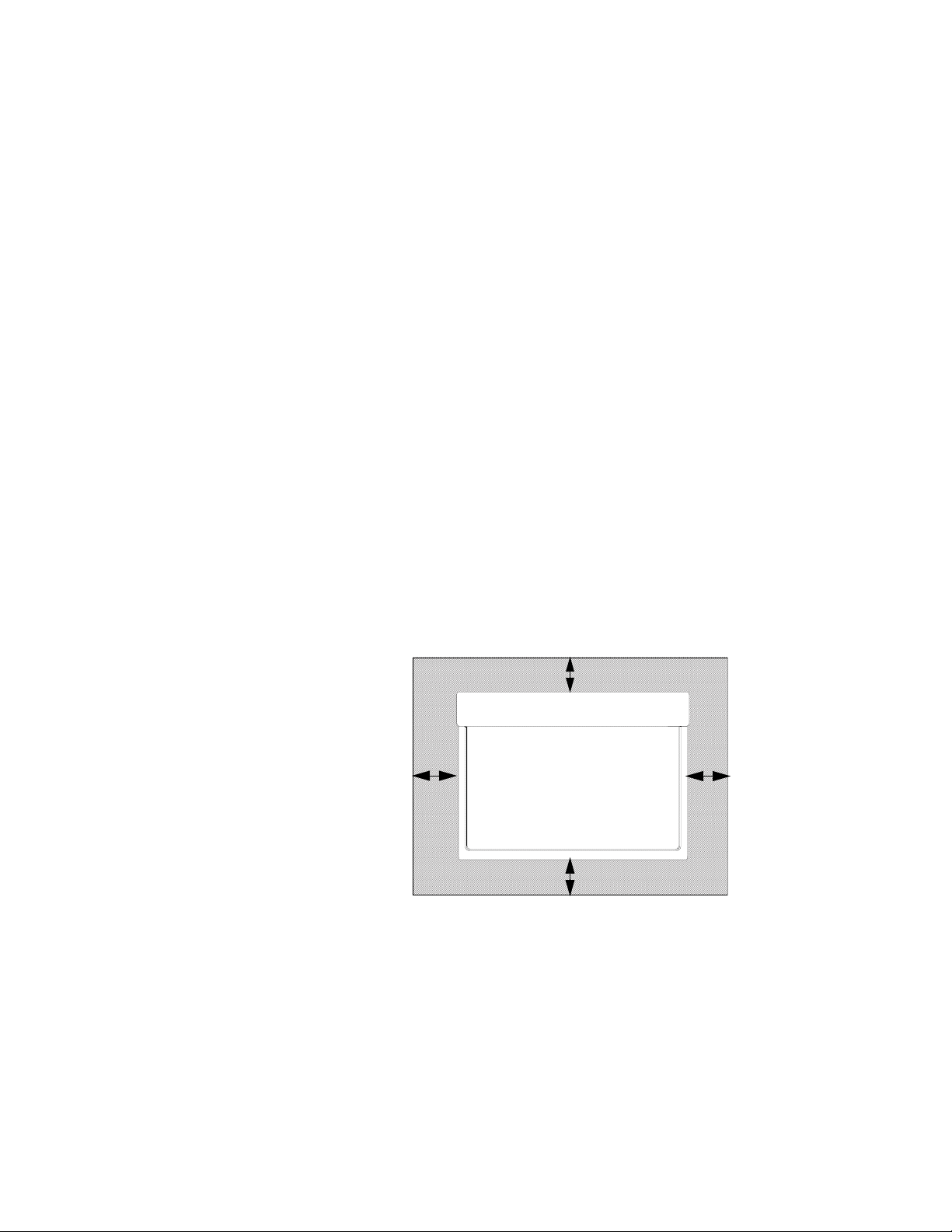
• When mounting the interactive display in a recessed area, such as in a wall, leave
at least 4" (10 cm) of space between the interactive display and the wall for proper
ventilation.
Page 17
9 | CHAPTER 2 – INSTALLING THE INTERACTIVE DISPLAY
56"
(142 cm)
38"
(96.5 cm)
Mounting the Interactive Display
Trained, professional installers are required to install the interactive display. The
SMART product warranty doesn’t cover damage caused by improper installation,
remodelling or natural disasters. Failure to comply with recommendations in this guide
could void the warranty.
WARNINGS
• Prior to mounting the interactive display, inspect the location to ensure that it
is strong enough to support the weight of the unit. The interactive display
weighs 132 lb. (60 kg).
• Do not mount the interactive display yourself. A trained, professional
installation team of three or more installers is required.
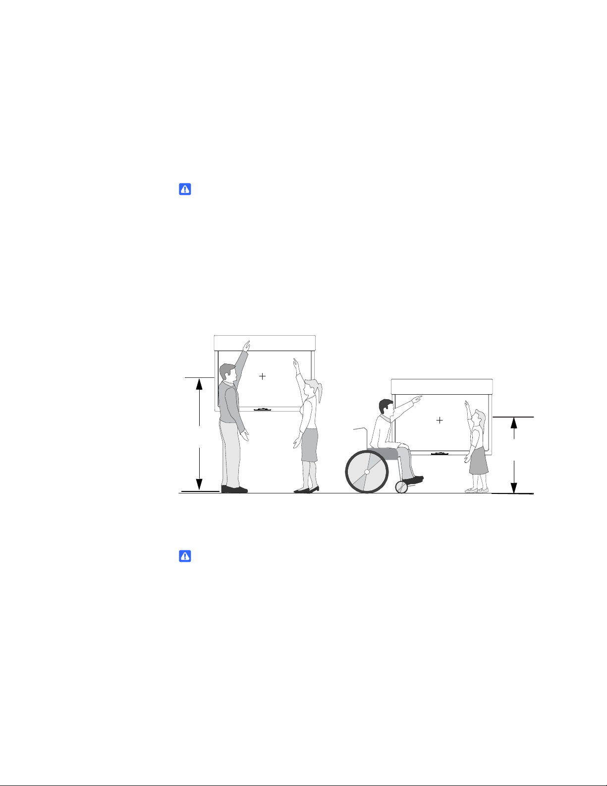
Recommended Mounting Height
Use the illustration below to determine the appropriate height for your interactive
display.
Important Mounting Considerations for Trained Installers
WARNING
Use an installation team of three or more trained, professional installers.
Consider the following when mounting the interactive display on a wall:
• Inspect the installation location to ensure that it’s strong enough to support the
weight of the interactive display. Not all walls are capable of supporting the weight
of the interactive display.
• To ensure safe installation, use two or more brackets to mount the interactive
display. Mount the interactive display to at least two points on the installation
location.
Page 18

10 | CHAPTER 2 – INSTALLING THE INTERACTIVE DISPLAY
• When using mounting accessories, they must comply with the VESA-compatible
(FDMlv1) mounting method.
• Use M6 screws of the appropriate length.
• The recommended fasten force is 470–635 N·cm. Mounting interfaces that
comply with the UL1678 standard in North America are recommended.
• Refer to the instructions included with the mounting equipment for detailed
information.
Consider the following when mounting the interactive display on a stand:
• Follow the instructions included with the stand or mounting apparatus. Use only
those devices recommended by the manufacturer.
• Install the interactive display carefully and avoid pinching your fingers.
• To ensure the interactive display doesn’t tip, fasten it to a wall using a cord or
chain. Ensure the wall and all fastening materials can support the weight of the
interactive display.
Page 19

Chapter 3
Setting Up the Interactive Display
The following chapter includes information on connecting external equipment,
connecting the power cord, attaching the cable cover and installing batteries into the
pencil and remote control.
Topics in this chapter include the following:
• Making Power and Computer Connections on page 12
• Installing SMART Software on page 13
• Enabling the Pencil on page 15
• Enabling the Wireless Remote Control on page 16
• Connecting External Equipment with the Terminal Panels on page 18
Page 20
12 | CHAPTER 3 – SETTING UP THE INTERACTIVE DISPLAY
Display VGA
Cable
Display
Power Cord
Touch Connection
Panel Power Cord
Internet
Connection
Touch Connection
Panel USB 2.0 Cable
Computer
Power Cord
Making Power and Computer Connections
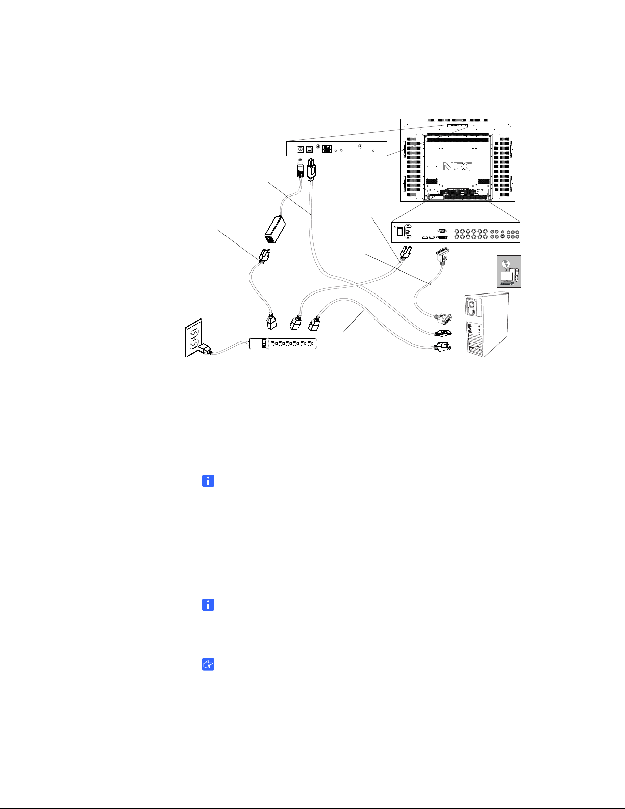
To make power and
computer connections
1. Connect the supplied VGA cable from your computer or SMART hub’s video
2. Connect the supplied power cable from the AC IN connector in the interactive
3. Connect the supplied power cable from the touch connection panel of the
4. Connect the supplied USB 2.0 cable from the touch connection panel to a USB
5. Connect your computer to the Internet.
6. Connect the power cable from your computer to the wall outlet.
output connection to the terminal pane. For more information, see Connecting
External Equipment with the Terminal Panels on page 18.
display’s bottom terminal panel to the AC power outlet.
NOTE
Optionally, you can cover the bottom terminal panel with the supplied cover to
secure the cables. Six screws are supplied for this cover.
interactive display to the AC power outlet.
2.0 receptacle on the computer.
NOTE
USB 1.1 cables or receptacles result in reduced performance.
IMPORTANT
If your interactive display was purchased with SMART Meeting Pro Premium,
you require an Internet connection for software installation.
Page 21

13 | CHAPTER 3 – SETTING UP THE INTERACTIVE DISPLAY
Turning On Your Interactive Display
To turn on the
interactive display
1. Turn on the computer.
2. Press the main power switch on the bottom terminal panel to turn on the
interactive display. For more information about the bottom terminal panel, see
page 18.
Your computer’s logon screen or desktop appears on the screen. If you don’t see
either, refer to the Troubleshooting on page 29.
NOTE
You can interact with the computer using a keyboard or mouse. In order to interact
by touch with the interactive display, you need to install SMART software.
Installing SMART Software
To use the interactive display, you need to install software on the interactive display’s
computer. This software includes:
• SMART Product Drivers, which enables touch interactivity and digital ink.
• SMART Notebook collaborative learning software from the included
installation CD.
To install
SMART Notebook and
SMART Product Drivers
OR
SMART Meeting Pro Premium collaboration software from an Internet download.
Installing SMART Notebook on Your Computer
The SMART Notebook CD includes two components:
• SMART Product Drivers
• SMART Notebook
IMPORTANT
• An Internet connection is recommended during installation to get a software
activation key and download software updates.
• For computer requirements, see the SMART Notebook release notes
(document 126571
1. Place the included installation CD in the computer’s CD tray.
The installation wizard appears.
).
Page 22

14 | CHAPTER 3 – SETTING UP THE INTERACTIVE DISPLAY
2. Follow the on-screen instructions. You will be prompted to enter your product
activation key. You must register your interactive display online using the serial
number found underneath the pencil ledge.
3. Click the SMART Board icon in the notification area (Windows computers) or
the Dock (Mac computers), and then select Check for Updates.
The SMART Product Update window appears.
4. Follow the on-screen instructions to update to the latest versions of both SMART
Notebook and SMART Product Drivers.
Installing SMART Meeting Pro Premium on Your computer
The SMART Meeting Pro Premium software download includes two components:
• SMART Product Drivers
• SMART Meeting Pro Premium
To download SMART
Meeting Pro Premium
To install SMART Meeting
Pro Premium and SMART
Product Drivers
IMPORTANT
• SMART Meeting Pro Premium is available only as an Internet download.
• This software requires a computer with a Windows operating system. For
other computer requirements, see the SMART Meeting Pro Premium release
notes (document 144278
• Your product ships with an activation key for SMART Meeting Pro Premium.
Please retain this activation key for your records.
1. Go to www.smarttech.com/downloads
2. Click the SMART Meeting Pro Premium link.
3. Click the Download link.
4. Follow the onscreen instructions to save the
SMARTMeetingProPremiumWrapper.exe file to your desktop.
1. Double-click the SMARTMeetingProPremiumWrapper.exe file.
2. Follow the on-screen instructions. You will be prompted to enter your product
activation key.
).
.
3. Click the SMART Board icon in the notification area (Windows computers) or
Dock (Mac computers), and then select Check for Updates
The SMART Product Update window appears.
Page 23
15 | CHAPTER 3 – SETTING UP THE INTERACTIVE DISPLAY
4. Follow the on-screen instructions to update to the latest versions of both SMART
Meeting Pro Premium and SMART Product Drivers.
Enabling the Pencil
Once you install SMART Product Drivers, you can interact with your computer’s
desktop and applications by touching the screen with a finger or other object. Your
interactive display includes a battery-powered pencil that provides greater touch
precision and ease of use, and allows you to draw with digital ink.
Installing a Battery in the Pencil
The pencil is powered by the included AAA battery.
To install a battery
in the pencil
1. Grasp the eraser end of the pencil in one hand and the top of the pencil in the
other, and then carefully pull the two sections apart.
2. Insert the supplied AAA battery into the battery compartment, matching the
markings on the holder to the markers on the battery.
3. Carefully push the two sections of the pencil together, and then place the pencil
on the interactive display’s pencil ledge.
CAUTION
Use the pencil carefully. Dropping it can break it.
Page 24

16 | CHAPTER 3 – SETTING UP THE INTERACTIVE DISPLAY
Using the Pencil
The pencil provides more precise touch contact for both drawing and mouse-actions.
To use the pencil Drag the pencil nib across the screen to create digital ink.
OR
Press an item or icon on the desktop as you would click a mouse.
If your pencil doesn’t draw digital ink or allow interaction with the desktop, see
Troubleshooting Pencil Issues on page 41.
Enabling the Wireless Remote Control
Your wireless remote control replicates many of the features found in the control
panel, allowing you to turn the interactive display on or off, or access monitor display
and audio settings from a distance of 23' (7 m).
Installing Batteries in the Wireless Remote Control
WARNING
Do not touch exposed battery acid.
CAUTIONS
• Incorrect use of batteries can result in leaks or bursting.
• Do not mix battery brands.
• Do not combine new and old batteries. it can shorten a battery’s life or, cause
it to leak battery acid.
• Remove dead batteries immediately to prevent battery acid from leaking into
the battery compartment.
To install batteries 1. Press the door on the underside of the wireless remote, and then slide it to open
the cover.
2. Insert two 1.5V AA batteries in the remote control. Ensure the (+) and (-) markings
on the batteries align with the markings in the remote control.
3. Replace the cover.
Page 25

17 | CHAPTER 3 – SETTING UP THE INTERACTIVE DISPLAY
TIP
If you don't intend to use the wireless remote control for a long period of time,
remove the batteries.
The Wireless Remote Control Sensor
The wireless remote control sensor is located in the lower-right corner of the
interactive display. It allows remote control of the LCD monitor from a distance of 23'
(7 m).
For more information on the wireless remote control range, see Wireless Remote
Control Range on page 24.
Using the Wireless Remote Control
The wireless remote control allows you to adjust display, audio and power settings.
For more information on the wireless remote control buttons, see Wireless Remote
Control Buttons on page 25.
If your wireless remote control doesn’t allow you to turn your interactive display on or
off or to view display settings, see Troubleshooting Wireless Remote Control Issues
on page 36.
Page 26

18 | CHAPTER 3 – SETTING UP THE INTERACTIVE DISPLAY
14
2
36
5
8
7
10
911 14
13
12
16
17
57
15
18
Connecting External Equipment with the Terminal Panels
The interactive display’s terminal panels enable you to connect external equipment to
the interactive display.
Bottom Terminal Panel
1 Main Power Switch 8 RGB/HV OUT (BNC)
2 AC IN connector 9 VIDEO IN connector (BNC and
RCA)
3 DISPLAYPORT connector 10 VIDEO OUT connector (BNC)
4 HDMI connector 11 DVD/HD connector (RCA)
5 DVI IN (DVI-D) 12 S-VIDEO IN connector (Mini DIN
4 pin)
6 VGA IN (mini D-Sub 15 pin) 13 AUDIO IN 1, 2, 3
7 RGB/HV IN [R, G, B, H, V] (BNC) 14 AUDIO OUT
Side Terminal Panel
15 External speaker terminal 16 LAN port (RJ-45)
16 External control (D-sub 9 pin) 18 Wired remote control in/out
Page 27

19 | CHAPTER 3 – SETTING UP THE INTERACTIVE DISPLAY
To connect external
equipment
1. Turn off your interactive display.
2. Ensure your external equipment is connected to its power source and is turned
off.
3. Connect the interactive display to the external equipment with an approved cable,
ideally supplied with the external equipment.
4. Turn on the interactive display and the external equipment.
Page 28

20 | CHAPTER 3 – SETTING UP THE INTERACTIVE DISPLAY
Page 29

Chapter 4
Using the Interactive Display
This chapter includes information on how to use your interactive display, turning your
interactive display on and off, turning your LCD screen on and off, controlling your
computer by pressing the screen, using the remote control, and more.
Topics in this chapter include the following:
• Turning the Interactive Display On and Off
– Turning On the Interactive Display on page 22
– Turning Off the Interactive Display on page 22
– Using Power Management on page 22
• Using the Touch Interactive Screen on page 23
• Using the Wireless Remote Control
– Wireless Remote Control Range on page 24
– Wireless Remote Control Buttons on page 25
Page 30

22 | CHAPTER 4 – USING THE INTERACTIVE DISPLAY
Turning the Interactive Display On and Off
Turning On the Interactive Display
To turn on the
interactive display
To turn off the
interactive display
1. Set the interactive display’s main power switch to on. This is on the terminal
panel, see page 2.
2. Press the power button on the control panel.
OR
Press the power button on the remote control.
3. Turn on the computer.
Turning Off the Interactive Display
1. Turn off your computer.
2. Press the power button on the control panel.
OR
Press the power button on the remote control.
3. Set the LCD monitor’s main power switch to off. This is on the terminal panel, see
page 2.
Using Power Management
The LCD monitor follows the VESA approved Display Power Management (DPM)
function.
Power management is an energy-saving function that enables your LCD monitor to
automatically enter a power-saving mode if you haven’t used the keyboard or the
mouse for a fixed period. This reduces the power consumption of the LCD monitor
and potentially increases the life of the interactive display.
If your LCD monitor enters power-saving mode, you can turn it on at any time by
touching the screen.
Page 31

23 | CHAPTER 4 – USING THE INTERACTIVE DISPLAY
Using the Touch Interactive Screen
Using the interactive display, you can perform normal computer operations by
pressing the with your finger and you can write in digital ink using the supplied pencil.
CAUTIONS
• Write with light pressure on the surface. Writing with excessive force can
damage the screen. SMART Technologies is not responsible for damage to
your LCD monitor incurred by improper use.
• Replace the pencil nib when it wears down. If a pencil nib wears down too far,
you might scratch or damage the screen. For more information, see page 45.
• Do not touch the screen with sharp or pointed objects such as fingernails,
keys, pens or jewelry.
To left-click Press the screen with your finger.
To right-click Press the screen with your finger and wait until the menu appears.
To write or draw 1. Pick up the supplied pencil.
2. Write or draw on the screen.
To erase 1. Pick up the supplied pencil.
2. Press the eraser end of the pencil on the screen, and then move the eraser over
the digital ink you want to erase.
OR
Press the eraser end on the screen, move it in a circle around the area you want
to erase, and then tap the middle of the circle with the eraser.
Using the Wireless Remote Control
The wireless remote control enables you to turn the LCD monitor on and off, change
the input source, change the volume, and more. You can also use the remote control
to open the on-screen menu, and then change the monitor’s settings.
If your wireless remote control doesn’t respond, see Troubleshooting Wireless
Remote Control Issues on page 36.
Page 32
24 | CHAPTER 4 – USING THE INTERACTIVE DISPLAY
30º
30º
CAUTIONS
• Do not subject the wireless remote control to strong shock.
• Do not allow water or other liquids to splash the remote control. If the remote
control gets wet, wipe it dry immediately.
• Avoid exposing the wireless remote control to heat or steam.
• Do not open the wireless remote control except for the battery compartment.
IMPORTANT
The remote control system can’t function when strong illumination strikes the
remote control sensor or when there is an object in its path.
Wireless Remote Control Range
The wireless remote control has a range of 23' (7 m) and an angle of 30º from
perpendicular to the wireless remote control sensor, which is located in the lower-left
corner of the display.
Page 33
25 | CHAPTER 4 – USING THE INTERACTIVE DISPLAY
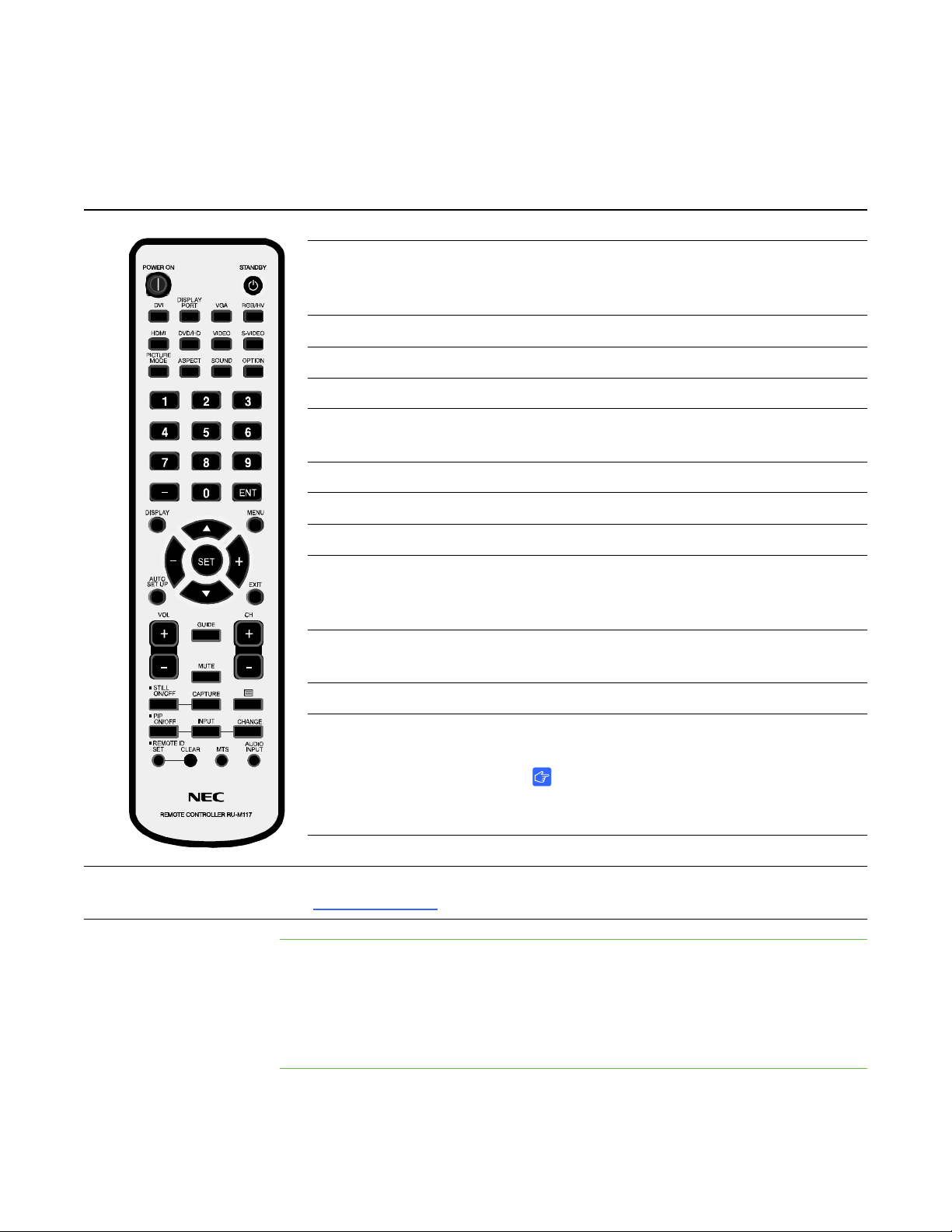
Wireless Remote Control Buttons
The table below explains the function of the most commonly used buttons.
POWER ON Switches the power on/standby
Input buttons (8) Selects input signal for the display. Choose
from DVI, DISPLAY PORT, VGAM, RGB/RV,
HDMI, DVD, VIDEO or S-VIDEO
PICTURE MODE Selects picture mode
ASPECT Selects picture aspect
SOUND Selects artificial surround sound
Number pad Press buttons to set and change passwords,
change channel and make settings
DISPLAY Turns the on-screen display menu on and off
MENU Turns the menu mode on and off
To use the wireless
remote control
AUTO SET UP Enters auto setup menu
UP/DOWN Acts as button to move the highlighted area up
or down to select adjustment items within the
on-screen display menu
+/- Increases or decreases the adjustment level
within the on-screen display menu
SET Makes selection
VOL +/- Increases or decreases audio output level
IMPORTANT
You must add speakers to the interactive
display to have audio output.
CH +/- Changes the channel for the interactive display
For other buttons, see the NEC MultiSync® S521 User’s Manual
(document 145185
Point the top of the remote control toward the wireless remote control sensor when
you press the buttons.
).
Use the remote control within approximately 23' (7 m) of the remote control sensor or
at a horizontal and vertical angle of 30° within a distance of about 10' (3.5 m).
Page 34

26 | CHAPTER 4 – USING THE INTERACTIVE DISPLAY
Selecting a Video Source
You can change the video source of the LCD monitor.
To change a video source Press the INPUT button on the LCD monitor’s control panel until the LCD monitor
displays the video source you want.
OR
Press the INPUT button on the remote control until the LCD monitor displays the video
source you want.
NOTE
Your interactive display includes a VGA cable to connect your computer to your
interactive display. You can use other connection types.
Displaying LCD Monitor Information
You can view on-screen information about the LCD monitor, such as the monitor’s
current input source or current aspect ratio.
To dis p l ay
monitor information
To adjust the volume
using the control panel
To adjust the volume
using the remote control
Press the DISPLAY button on the remote control.
Adjusting Audio Volume
You can change the volume of connected speakers (the interactive display doesn’t
have internal speakers) using the control panel or the remote control.
1. If the on-screen menu is currently displayed, press the Menu button to close the
on-screen menu.
2. Press the + or - button to increase or decrease the volume.
Press the VOL + or - button to increase or decrease the volume.
Page 35

27 | CHAPTER 4 – USING THE INTERACTIVE DISPLAY
Changing Settings in the On-Screen Menu
You can adjust many of the LCD monitor’s settings using the on-screen menu,
including the brightness, contrast, and many more.
To change settings in the
on-screen menu
1. Press the MENU button.
The on-screen menu appears.
2. Press the up or down arrows to select the settings you want to change.
3. Press SET.
4. Press the up or down arrows to select the setting you want from the sub-menu.
OR
Press the + or - buttons to increase or decrease the value.
5. If you want to change another setting, press the EXIT button to return to the main
menu, and then repeat steps 2 through 4.
6. When you finish changing settings, press the MENU button to close the on-screen
menu.
Locking the Control Panel
You can lock the current control panel settings using control Key Lock mode. When
this mode is active, the panel ignores any input on the control panel.
To lock or unlock the
control panel
Press the control panel’s up and down arrows simultaneously for more than three
seconds to either lock or unlock the control panel.
Page 36

28 | CHAPTER 4 – USING THE INTERACTIVE DISPLAY
Page 37

Chapter 5
Troubleshooting
This chapter helps you identify and resolve various issues in the field. If issues persist,
contact SMART technical support
Support on page 49.
Topics in this chapter include the following:
• Troubleshooting Quick Reference Table on page 30
• Troubleshooting Power Issues on page 31
• Troubleshooting Picture Issues on page 32
• Troubleshooting Audio Issues on page 35
• Troubleshooting with the Wireless Remote Control Sensor LED on page 35
• Troubleshooting Interactivity Issues on page 37
. For SMART contact information, see Technical
• Troubleshooting Wireless Remote Control Issues on page 36
For additional troubleshooting suggestions, see the NEC MultiSync S521 User’s
Manual (document 145185
).
Page 38

30 | CHAPTER 5 – TROUBLESHOOTING
Troubleshooting Quick Reference Table
Symptoms Cause Solution
There is no image on your
screen.
There is a persistent image
on your screen.
There are unstable images
on the screen.
There is an unfocused or
blurry image on the screen.
There is no sound from
your display.
Your computer is in Standby
mode.
OR
There is no power to your
computer, interactive display or
touch connection panel.
OR
Your computer isn’t connected
to the interactive display.
An image displayed for too
long.
Connection issues
OR
Display card issues
Conflicting display and
computer image settings.
Speakers aren’t included with
the interactive display, and
none have been added.
OR
Touch the panel to activate
your computer.
See Making Power and
Computer Connections on
page 12.
See Troubleshooting
Persistent Image Issues on
page 33
See Troubleshooting Unstable
or Unfocused Images on
page 34.
See Troubleshooting
Resolution Issues on page 34.
Install speakers and connect
them to either the computer or
the LCD display side terminal
panel. See Connecting
External Equipment with the
Terminal Panels on page 18.
The interactive display
doesn’t respond to your
touch.
The screen pointer doesn’t
appear where you touch.
Audio settings are incorrect. See Troubleshooting Audio
Issues on page 35.
You don’t have a USB 2.0
cable connecting the touch
connection panel to the
computer.
The interactive display
cameras aren’t calibrated.
See Making Power and
Computer Connections on
page 12.
OR
If your interactive display is
mounted on a stand, see To
troubleshoot using LED status
and diagnostic lights on
page 38
See Troubleshooting
Calibration Issues on page 39.
Page 39

31 | CHAPTER 5 – TROUBLESHOOTING
Symptoms Cause Solution
Your pencil doesn’t draw
digital ink.
To troubleshoot
power issues
The pencil battery is dead.
OR
The pencil nib is worn.
OR
The pencil isn’t responding or
is behaving unexpectedly.
To install a battery in the pencil
on page 15.
See To replace the pencil nib
on page 45.
See To test your pencil on
page 41.
Troubleshooting Power Issues
Complete the following steps if you can’t turn on the interactive display.
1. Turn off the interactive display.
2. Disconnect the interactive display’s power cord from the power outlet.
The interactive display resets.
3. Connect the power cord to the power outlet.
4. Turn on the interactive display.
Page 40
32 | CHAPTER 5 – TROUBLESHOOTING
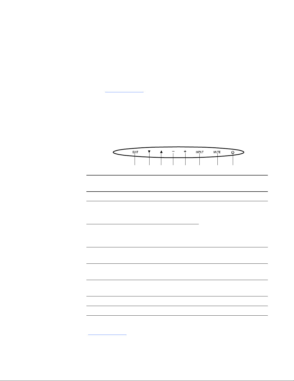
123456 78
Troubleshooting Picture Issues
Complete the following steps if your interactive display doesn’t display an image
correctly or any image at all. You can resolve these issues with the computer display
settings, the control panel settings or the wireless remote control (see page 23).
For additional troubleshooting suggestions, see the NEC MultiSync S521 User’s
Manual (document 145185
Adjusting the Screen with the Control Panel
The control panel enables you to turn the LCD monitor on and off, change the input
source, change the volume and more.
The control panel is on the right-hand underside of your interactive display.
).
Key Button
1 EXIT Closes the menu.
2 Down Highlights the option below
3 Up Highlights the option above
4 - Decreases the value of the
5 + Increases the value of the
6 INPUT Selects the value of the
7 MUTE Turns the audio on and off.
8 Power Turns the power on and off.
Function if the On-Screen
Menu Is Displayed
the currently highlighted
option.
the currently highlighted
option.
currently highlighted option.
currently highlighted option.
currently highlighted option.
Function if the On-Screen
Menu Isn’t Displayed
Opens the on-screen menu.
Decreases the audio output
level.
Increases the audio output
level.
Switches between available
input settings.
For more information on these buttons, see the NEC MultiSync S521 User’s Manual
(document 145185
).
Page 41

33 | CHAPTER 5 – TROUBLESHOOTING
Troubleshooting No Picture on the Screen
To troubleshoot
no picture issues
1. Turn off the LCD monitor, turn off the interactive display, and then turn off the
computer.
2. Disconnect the video cable (Usually VGA) that connects the interactive display’s
bottom terminal panel to the computer.
3. Check the video cable for bent or pushed-in pins. If the cable is damaged, replace
it.
4. Install the video cable between the interactive display’s bottom terminal panel and
the computer.
5. Turn on the computer, turn on the interactive display, and then turn on the LCD
monitor.
6. If the screen still doesn’t display an image, there could be an issue with the
computer’s display card. Ask someone with knowledge of display cards to confirm
the following:
– Is the display card correctly installed in its slot?
– Is a supported mode selected on the display card or system? For more
information on changing Graphics modes, consult the documentation
supplied with the display card or system.
– Is the display card compatible with the interactive display?
For additional troubleshooting suggestions, see the NEC MultiSync S521 User’s
Manual (document 145185).
Troubleshooting Persistent Image Issues
LCD technology can experience a phenomenon known as image persistence. Image
persistence occurs when a residual or ghost image of a previous image remains
visible on the screen. Although image persistence on an LCD monitor isn’t permanent
(unlike CRT monitors), you should avoid displaying images on the screen for a long
period of time.
TIPS
To reduce the risk of image persistence:
• Display moving images at regular intervals whenever the screen is idle.
• Turn off the interactive display when it isn’t in use.
• Activate a screen saver for your operating system.
Page 42

34 | CHAPTER 5 – TROUBLESHOOTING
To remove a
persistent image
To troubleshoot
unstable or unfocused
image issues
1. Turn off the interactive display and the computer.
2. Leave the interactive display and the computer off for the same length of time as
the persistent image was on-screen. For example, if the interactive display
displayed an image for one hour and a residual image remains, don’t turn on the
computer and the interactive display until after a minimum of one hour.
Troubleshooting Unstable or Unfocused Images
Complete the following steps if your LCD screen displays an unstable or unfocused
image.
1. Turn off the interactive display, and then turn off the computer.
2. Disconnect the video cable that connects the interactive display’s bottom terminal
panel to the computer.
3. Connect the video cable from the interactive display’s bottom terminal panel to the
computer.
4. Turn on the interactive display, and then turn on the LCD monitor.
To troubleshoot
resolution issues
5. If the LCD monitor still displays an unstable or unfocused image, open the
on-screen menu, and then change the image settings in the Adjust sub-menu. If
this resolves the issue, you could need to change the image settings again the
next time you change display modes.
Troubleshooting Resolution Issues
Open the on-screen menu, and adjust the resolution. For more information, see
Wireless Remote Control Buttons on page 25.
For additional troubleshooting suggestions, see the NEC MultiSync S521 User’s
Manual (document 145185).
Page 43

35 | CHAPTER 5 – TROUBLESHOOTING
Troubleshooting Audio Issues
Complete the following steps to resolve issues with the audio output.
NOTE
Speakers aren’t included with the interactive display. You must add external
speakers for audio output.
To troubleshoot
audio issues
To troubleshoot
issues using the LED
1. Confirm that the audio cable is connected correctly.
2. Confirm that mute isn’t activated.
3. Confirm that the volume isn’t set to its minimum setting.
For additional troubleshooting suggestions, see the NEC MultiSync S521 User’s
Manual (document 145185).
Troubleshooting with the Wireless Remote Control Sensor LED
Complete the following steps if the power indicator in the wireless remote control
sensor (located in the lower-right corner of your interactive display) doesn’t glow.
1. Confirm that the computer isn’t in power-saving by touching the screen or
touching a connected keyboard or mouse. If this doesn’t resolve the issue,
continue with the following steps.
2. Turn off the interactive display, and then turn off the computer.
3. Disconnect the interactive display’s power cord from the power outlet.
4. Connect the interactive display’s power cord to the power outlet.
5. Turn on the computer, and then turn on the interactive display.
6. If this doesn’t resolve the issue, the LCD monitor’s Power Indicator setting could
be set incorrectly. Open the on-screen menu, using either the control panel or the
wireless remote control, and then select the Multi Display > Power Indicator
sub-menu.
7. Ensure the Power Indicator option is set to ON.
Page 44

36 | CHAPTER 5 – TROUBLESHOOTING
To interpret a
flashing red LED
To troubleshoot issues
with the remote control
If the LED flashes red six times, and then the LCD monitor turns off, the internal
temperature of the LCD monitor is higher than its normal operating temperature. Do
not turn on the monitor again until the internal temperature has reduced to its normal
operating temperature.
OR
If the LED flashes red more than six times, the LCD monitor could have detected a
component failure. Please contact SMART technical support
see Technical Support on page 49.
. For contact infromation,
Troubleshooting Wireless Remote Control Issues
1. Confirm that the wireless remote control is pointing at the wireless remote control
sensor.
2. Confirm that there are no object’s between the remote control and the sensor. For
more information on the optimum angle for the wireless remote control, see Using
the Wireless Remote Control on page 23.
3. Confirm that there is no direct sunlight or strong illumination reaching the remote
control sensor of the LCD monitor, or when there is an object in the path.
4. Confirm that the remote control’s batteries are inserted correctly.
5. Replace the batteries.
6. For additional troubleshooting suggestions, see the NEC MultiSync S521 User’s
Manual (document 145185).
Page 45

37 | CHAPTER 5 – TROUBLESHOOTING
Troubleshooting Interactivity Issues
Follow these steps if you can see your computer’s desktop on your interactive display,
but you are unable to interact well (or at all) with the desktop.
These are commonly on of the following issues:
• Touch connection panel issues where your touch on the interactive display has no
effect.
• Orientation issues where your touch on the interactive display makes a mouse
appear in a location other than where you touched.
• Pencil issues where your pencil doesn’t respond or doesn’t respond well.
Troubleshooting Touch Connection Panel Issues
The touch connection panel gathers information from the interactive display and
passes that information to the computer.
To reset the
touch connection panel
A basic reset resolves most touch connection panel issues. You can also use the LED
status lights to interpret other touch connection panel issues.
NOTE
If your interactive display is mounted on the wall, you could require a ladder and a
mirror to observe the LED status lights.
1. Disconnect the touch connection panel power source.
2. Connect the touch connection panel power source.
The touch connection panel resets, but retains control and screen calibration
data.
Page 46

38 | CHAPTER 5 – TROUBLESHOOTING
Diagnostic LED
Status LED
To troubleshoot using
LED status and
diagnostic lights
1. Observe the status lights on the touch connection panel.
2. Use the following table
Diagnostic
LED
Status
LED
Touch Connection Panel
Condition
Off Off Touch connection panel is
turned off or power cable is
disconnected.
Off Flashing
green
Green
Green Touch connection panel is
OR
Software is starting or touch
connection panel is initializing.
functioning within normal
parameters.
Alternating
green and
orange
Solution
Connect the power cable to the
touch connection panel.
Don’t touch your panel until
initializing is complete.
None.
Flashing
green
Green
OR
Alternating
green and
orange
Flashing
red
Flashing
green
Flashing
orange
Green No SMART software detected. Start SMART software.
Red Error detected. Run the SMART Connection
Wizard’s troubleshooting
procedures to determine the
cause.
Red No USB connection. Check the cable between the
touch connection panel and
computer.
Red No SMART software detected. Start SMART software, and
then run the SMART
Connection Wizard’s
troubleshooting procedures.
Red SMART software isn’t
Restart your computer.
responding.
Page 47

39 | CHAPTER 5 – TROUBLESHOOTING
Diagnostic
LED
Green
OR
Alternating
green and
orange
Flashing
green
Red Flashing
Off Flashing
Status
LED
Flashing
orange
Flashing
orange
orange
orange
Touch Connection Panel
Condition
Touch connection panel is
updating firmware.
No USB connection. Check the cable between the
Corrupted firmware. Run the SMART Firmware
Computer is in Standby mode. Turn on the computer.
Solution
Wait for the update to finish.
touch connection panel and the
computer.
CAUTION
Do not disconnect the
cable. Disconnecting the
cable could cause
computer memory loss.
Upgrade Wizard.
To calibrate the
interactive display
Troubleshooting Calibration Issues
When the location of your touch is misinterpreted (a pointer appears a distance from
the actual contact), calibrate your interactive display.
1. Press the SMART Board icon in the notification area (Windows computers)
or the Dock (Mac computers), and then select Control Panel.
The SMART Control Panel opens
2. Press Connection Wizard.
The SMART Connection Wizard appears and scans for SMART products.
Your interactive display appears as SMART Board (0x3) - on USB in the list with
a check mark beside it.
3. Select your interactive display, and then press Next (Windows computers) or
Continue (Mac computers).
If your cameras are working correctly, they appear in a list with a check mark
beside each camera.
Page 48
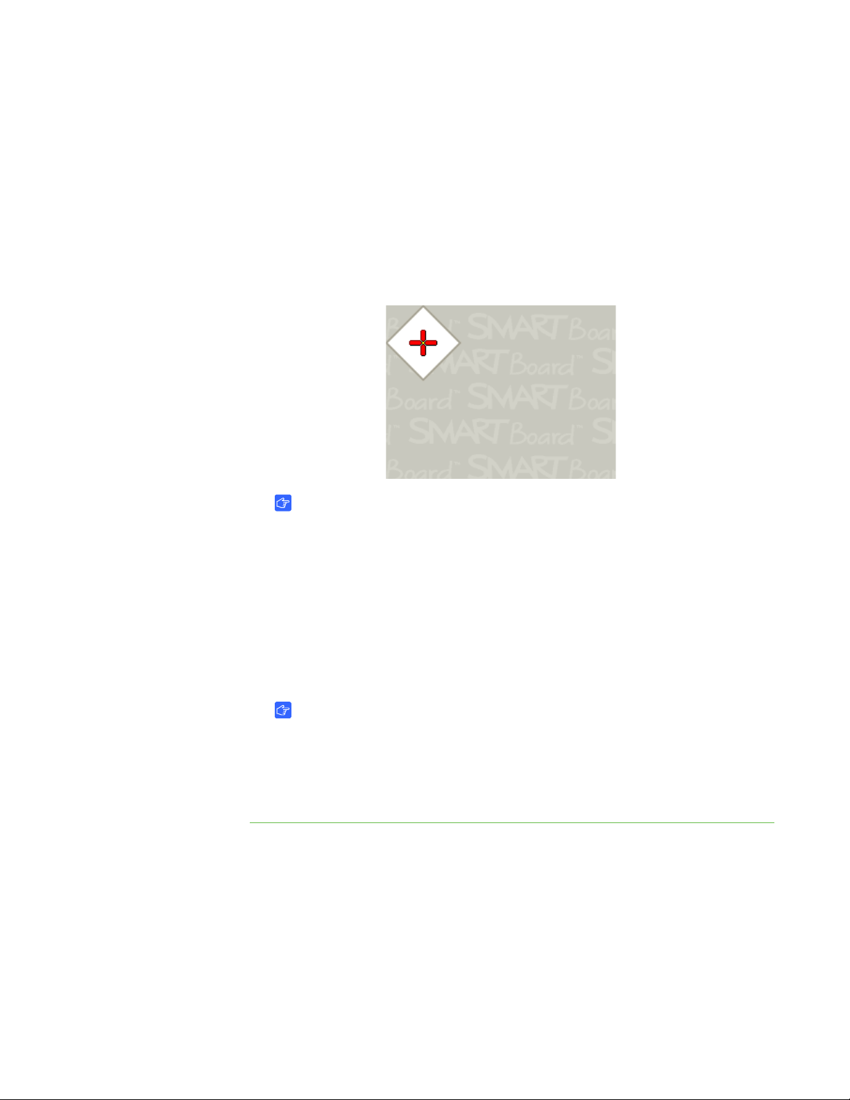
40 | CHAPTER 5 – TROUBLESHOOTING
4. Press Next (Windows computers) or Continue (Mac computers).
The pencil test window opens. If you want to test the pencil, see To test your
pencil on page 41.
5. Press Next (Windows computers) or Continue (Mac computers).
The Eraser Test window appears.
6. Press Next (Windows computers) or Continue (Mac computers).
The Calibration window opens.
IMPORTANT
The Calibration window can take a minute or more to open. Do not touch the
screen surface until you see the image above.
7. Use the pencil nib to press the 15 red targets as they appear on the screen. Move
the nib to the center of each target, and then wait until the target turns green
before you lift the pencil. When you lift the pencil, the target moves to the next
calibration point. Continue until you’ve pressed all the targets. At the end of the
procedure, you hear a beep.
The Calibration window disappears.
IMPORTANT
– When you calibrate your interactive display, keep your pencil at a right
angle to the screen.
– You can re-calibrate a target by pressing the left arrow key on the
keyboard.
Page 49

41 | CHAPTER 5 – TROUBLESHOOTING
Troubleshooting Pencil Issues
If your interactive display responds to your touch, but not to your pencil, follow the
steps below.
To trouble shoot
pencil issues
To test your pencil 1. Press the SMART Board icon in the notification area (Windows computers)
1. Examine the pencil nib. If the nib is worn, replace it. See Replacing the Pencil Nib
on page 45.
2. Change the battery in the pencil. See Replacing the Pencil Battery on page 44.
3. Perform a pencil test.
or the Dock (Mac computers), and then select Control Panel.
The SMART Control Panel opens
2. Press Connection Wizard.
The SMART Connection Wizard appears and scans for SMART products.
Your interactive display appears as SMART Board (0x3) - on USB in the list with
a check mark beside it.
3. Select your interactive display, and then press Next (Windows computers) or
Continue (Mac computers).
4. Press Next (Windows computers) or Continue (Mac computers).
5. The pencil test window opens.
6. Tap the pencil nib on the picture of the target.
A message appears, indicating that your pencil is working correctly.
7. Tap the eraser on the picture of the target to ensure the eraser doesn’t work in the
pencil test, and then press Next (Windows computers) or Continue (Mac
computers).
The Eraser Test window appears.
8. Press the pencil’s eraser on the picture of the target.
A message appears, indicating that your eraser is working correctly.
9. Tap the pencil nib on the picture of the target to ensure that the pencil doesn’t
work in the eraser test, and then press Next (Windows computers) or Continue
(Mac computers).
Your pencil test is complete.
Page 50

42 | CHAPTER 5 – TROUBLESHOOTING
Page 51

Chapter 6
Maintaining Your Interactive Display
Properly maintained, your interactive display will provide years of use.
Topics in this chapter include the following:
• Cleaning the LCD Screen on page 43
• Maintaining Interactive Display Ventilation on page 44
• Maintaining the Pencil on page 44
• Checking the Interactive Display Installation on page 45
• Removing Your Interactive Display on page 46
• Transporting Your Interactive Display on page 46
Cleaning the LCD Screen
Follow these instructions to clean the LCD screen and to prevent damage to the
anti-glare coating and other product components.
CAUTIONS
• Do not touch the screen with sharp or pointed objects.
• Write with light pressure on the screen surface.
• Do not scratch the screen surface with your fingernails, keys or jewelry.
• Do not use permanent or dry-erase markers on the screen. If dry-erase
markers are used on the screen, remove the ink as soon as possible with a
lint-free, non-abrasive cloth.
• Do not rub the screen with a hard material.
• Do not apply pressure to the screen.
Page 52

44 | CHAPTER 6 – MAINTAINING YOUR INTERACTIVE DISPLAY
• Do not use a cleaning solution or glass cleaner, as they can deteriorate or
discolor the screen.
• Avoid touching the silver reflective tape on the border between the screen and
the bezel and ensure it stays dry. Damage to this strip affects touch
interactivity.
To clean the LCD screen 1. Shut off the computer, and then disconnect the power sources.
2. Wipe the LCD screen with a lint-free, non-abrasive cloth.
Maintaining Interactive Display Ventilation
Your interactive display requires ventilation to allow the fans to cool the interactive
display.
CAUTIONS
• Avoid setting up or using your interactive display in an area with excessive
levels of dust, humidity or smoke.
To replace the battery
• Wipe and clean accessible ventilation holes monthly.
• Remove the interactive display from the wall annually to clean the ventilation
holes in the back of the interactive display. See Removing Your Interactive
Display on page 46
Maintaining the Pencil
For trouble shooting steps, see Troubleshooting Pencil Issues on page 41
Replacing the Pencil Battery
Replace the pencil’s AAA battery when the Low Battery warning appears on your
screen or when your pencil no longer draws digital ink.
CAUTION
Rechargeable batteries are not recommended.
See Installing a Battery in the Pencil on page 15.
Page 53

45 | CHAPTER 6 – MAINTAINING YOUR INTERACTIVE DISPLAY
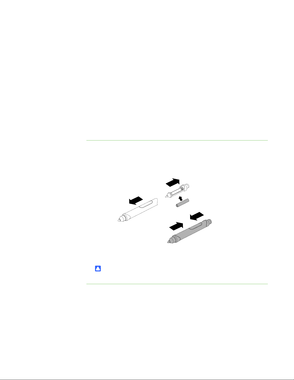
Nib
Worn Pencil Nib
New Pencil Nib
Replacing the Pencil Nib
CAUTION
Replace the pencil nib when it wears down. If a pencil nib wears down too far, you
could scratch or damage the screen’s anti-glare coating.
To replace the pencil nib 1. Carefully unscrew the cap surrounding the pencil nib.
2. Pull gently on the nib to remove it from the pencil.
3. Insert the new nib, and then replace the cap.
Checking the Interactive Display Installation
Regularly check the mounting location for signs of damage or weakness that can
occur over time.
Periodically check for loose screws, gaps, distortions, or other issues that could occur
with the mounting apparatus. If you find an issue, please refer to a trained,
professional installer.
Page 54

46 | CHAPTER 6 – MAINTAINING YOUR INTERACTIVE DISPLAY
Removing Your Interactive Display
To safely remove your interactive display, use three or more trained, professional
installers.
Removing the Interactive Display
• Follow the instructions included with the stand or mounting apparatus.
• Avoid pinching fingers.
• Do not place the interactive display on a sloping or unstable cart, stand or table,
because the interactive display can fall resulting in serious damage.
• Do not mount the interactive display face up, face down or upside down for an
extended period of time as it could cause permanent damage to the screen.
• Do not move the interactive display by hanging a rope or wire to the backside
handle. It can fall and cause personal injury.
Transporting Your Interactive Display
Save your original packaging so that you can repack your interactive display with as
much of the original packaging as possible. This packaging was designed with optimal
shock and vibration protection. If your original packaging isn’t available, you can
purchase the same packaging directly from your authorized SMART reseller
.
Page 55

Appendix A
Hardware Environmental Compliance
SMART Technologies supports global efforts to ensure that electronic equipment is
manufactured, sold and disposed of in a safe and environmentally friendly manner.
Waste Electrical and Electronic Equipment Regulations (WEEE Directive)
Waste Electrical and Electronic Equipment regulations apply to all electrical and
electronic equipment sold within the European Union.
When you dispose of any electrical or electronic equipment, including SMART
Technologies products, we strongly encourage you to properly recycle the electronic
product when it has reached end of its life. If you require further information, please
contact your reseller or SMART Technologies for information on which recycling
agency to contact.
Restriction of Certain Hazardous Substances (RoHS Directive)
This product meets the requirements of the European Union’s Restriction of Certain
Hazardous Substances (RoHS) Directive 2002/95/EC.
Consequently, this product also complies with other regulations that have arisen in
various geographical areas, and that reference the European Union’s RoHS directive.
Page 56

48 | APPENDIX A – HARDWARE ENVIRONMENTAL COMPLIANCE
Batteries
Batteries are regulated in many countries. Check with your reseller to find out how to
recycle used batteries.
There are special regulations that must be met when shipping a product that has a
lithium ion battery packaged with the product or shipping a lithium ion battery. When
returning a SMART Technologies product which contains a lithium ion battery or
returning a lithium ion battery, call SMART Technologies RMA for information on these
special shipping regulations:
• 1.866.518.6791, Option 4 (U.S./Canada)
• 1.403.228.5940 (all other countries)
Packaging
Many countries have regulations restricting the use of certain heavy metals in product
packaging. The packaging used by SMART Technologies to ship products complies
with applicable packaging laws.
Covered Electronics Devices
Many U.S. states classify monitors as Covered Electronic Devices and regulate their
disposal. Applicable SMART Technologies products meet the requirements of the
Covered Electronic Devices regulations.
U.S. Consumer Product Safety
Improvement Act
The United States has enacted the Consumer Product Safety Improvement Act which
limits the lead (Pb) content in products used by children. SMART Technologies is
committed to complying with this initiative.
Page 57

49 | APPENDIX B – CUSTOMER SUPPORT
Appendix B
Customer Support
Online Information and Support
Visit www.smarttech.com/support to view and download user’s guides, how-to and
troubleshooting articles, software and more.
Training
Visit www.smarttech.com/trainingcenter for training materials and information about
our training services.
Technical Support
If you experience difficulty with your SMART product, please contact your local
reseller before contacting SMART Technical Support. Your local reseller can resolve
most issues without delay.
NOTE
To locate your local reseller, visit www.smarttech.com/where
All SMART products include online, telephone, fax and e-mail support:
Online www.smarttech.com/contactsupport
Telephone +1.403.228.5940 or
Toll Free 1.866.518.6791 (U.S./Canada)
(Monday to Friday, 5 a.m. – 6 p.m. Mountain Time)
Fax +1.403.806.1256
E-mail support@smarttech.com
.
Shipping and Repair Status
Contact SMART’s Return of Merchandise Authorization (RMA) group, Option 4,
+1.866.518.6791, for shipping damage, missing part and repair status issues.
Page 58

50 | APPENDIX B – CUSTOMER SUPPORT
General Inquiries
Address SMART Technologies
3636 Research Road NW
Calgary, AB T2L 1Y1
CANADA
Switchboard +1.403.228.5940 or
Toll Free 1.866.518.6791 (U.S./Canada)
Fax +1.403.228.2500
E-mail info@smarttech.com
Warranty
Product warranty is governed by the terms and conditions of SMART’s “Limited
Equipment Warranty” that shipped with the SMART product at the time of purchase.
Registration
To help us serve you, register online at www.smarttech.com/registration
Page 59

Index
A
audio
troubleshooting, 35
volume, 26
B
batteries, 48
cautions, 16
install into pencil, 15
installing into the remote control, 16
C
cameras
location, 3
contact information, 50
control panel
location, 2, 3
locking, 27
covered electronic devices, 48
customer support, 49
G
general inquiries, 50
H
hardware environmental compliance,
47–48
I
Important Information, i
inquiries, 50
installation, 7
L
laptop shelf, 5
LCD screen
cleaning, 43
location, 2
left click, 23
Limited Equipment Warranty, 50
lithium ion batteries, 48
D
documentation, 49
draw, 23
E
environmental compliance, See
hardware environmental compliance
erase, 23
European Union regulations, 47
M
mobile stand, 5
mounting
installation team, 9
recommended height, 9
stand, 10
O
online support, 49
Page 60

52 | INDEX
P
packaging, 48
retain for moving, 46
pencil
battery, 15
enabling, 15
erase, 23
replace nib, 45
troubleshooting, 41
using, 16
write, 23
power
connectors, iii
management, 22
turning off, 22
turning on, 22
power connectors, 12
R
reflective tape, 3
location, 2
registration, 50
regulatory compliance, See hardware
environmental compliance
requirements
computer, 6
environmental, 6
right click, 23
RoHS directive, 47
T
technical support, 49
terminal panel
connections, 18
location, 2, 3
touch connection panel
location, 3
training, 49
troubleshooting
articles, 49
audio, 35
interactivity, 37
pencil, 41
picture, 32
power, 31
quick reference, 30
wireless remote control, 35
turn off the interactive display, 22
turn on the interactive display, 22
U
U.S. regulations, 48
user’s guides, 49
V
ventilation, 8, 44
VESA rear-mounting plate, 7
S
SMART Product Drivers, 13, 14
SMART software
SMART Meeting Pro Premium, 14
SMART Notebook, 13
SMART technical support, 49
stand
mobile, 5
mounting, 10
support, 49
W
warranty, 50
WEEE directive, 47
weight of interactive display, 8
wireless remote control
buttons, 25
installing batteries, 16
range, 24
sensor location, 2, 4
troubleshooting, 35
write, 23
Page 61

Page 62

Toll Free 1.866.518.6791 (U.S./Canada)
or +1.403.228.5940
www.smarttech.com
 Loading...