

Page 1

SMARTBoard®
6000Sand6000SProseries
interactive displays
INSTALLATION AND MAINTENANCE GUIDE
SBID-6265S | SBID-6275S | SBID-6286S | SBID-6265S-PW | SBID-6275S-PW | SBID-6286S-PW
SBID-6065S | SBID-6075S | SBID-6086S | SBID-6065S-PW | SBID-6075S-PW | SBID-6086S-PW
IDS665-1 | IDS675-1 | IDS686-1
Was this document helpful?
smar ttech.com/docfeedback/171414
Page 2

Learn more
This guide and other resources for SMARTBoard 6000S and 6000S Pro series
interactive displays are available in the Support section of the SMARTwebsite
(smarttech.com/support). Scan this QRcode to view these resources on your mobile
device.
Licenses
The ter ms HDMI and HDMI Hig h-Definition Multimedia Interface, and the HD MI l og o are trademarks o r re gi stere d trad emarks of H DMI Licensing LLC in the U nited S tates and
other co untries .
The Bluetoo th wo rd mark is owned by the Bluetooth SIG, Inc. and any use of such marks b y SMARTT echnolog ie sULC is under lice nse.
Trademark n ot ice
SMART Board , SMART No teb ook, SMART TeamWorks , SMART Mee ting Pro , Pe n I D, Hy Pr T ouch, Obje ct Awareness , Sil ktouch, Tool Expl orer, smarttech, the SMART log o and
all SMART taglines are trade marks or r eg iste red trademarks o f SMART Te chnologi es U LC i n the U .S. and/or other countries. The Bluetoo th wo rd mark is o wned b y the
Bluetooth SIG, I nc. and any use o f s uch marks by SMART Technolo gie s U LC i s under l icense . The Adopted Trad emarks HD MI, HDMI Hi gh-Definition Multimedia Interface, and
the H DMI Log o are trademarks o r re gi stere d trad emarks of H DMI Licensing Ad ministrator, Inc. in the U nited States and o ther countries. All other third-party pr od uct and
company names may be trad emarks of their r es pe ctive o wners .
Copyrigh t no tice
© 2 021 SMARTTe chnologi esU LC. All rig hts r es er ved . No part of this publication may be r ep ro duced , transmitted, transcrib ed , stor ed in a r etrie val sys tem or translated into
any language i n any form by any means without the pri or w ritten consent of SMARTTe chnolog ies ULC. Information i n this manual is subje ct to change without notice and d oe s not
rep re se nt a commitment on the part of SMART.
This p rod uct and/or use thereo f is cov ere d b y one or more of the follo wing U. S. p atents:
www.smarttech.com/patents
March 26 , 202 1
smar ttech.com/kb/171414 2
Page 3

Important information
WARNING
l Failure to follow the installation instructions included with
the display could result in injury and product dama ge
which may not be covered by the warr anty.
l Do not open or disassemble the display. You r isk
electrical shockfrom the high voltage inside the casing.
Opening the casing also voids the warranty.
l Do not stand (or allow children to stand) on a chair to
touch the surface of the display.Rather, mount the
product at the appropriate height.
l To reduce the risk of fire or electric shock,do not expose
the display to r ain or moisture.
l If the display requires replacement parts, make sure the
service technician uses replacement par ts specified by
SMARTTechnologies or parts with the same
characteristics as the original.
l Ensure that any cables that cross the floor to the display
are pr operly bundled and marked to avoid a trip hazard.
l Do not insert objects inside the cabinet ventilation holes,
because they couldtouch dangerous voltage points and
cause electric shock,fire or product damage which may
not be covered by the war ranty.
l Do not place heavy objects on the power cable. Dama ge
to the cable could cause shock,fire, or product damage
which may not be covered by the warr anty.
l Useonlyextension cords and outlets that can fully
accommodate the display’spolarized plug.
l Use the power cable provided with the display. If a power
cable is not supplied,contact your supplier. Use only
power cables that match the AC voltage of the power
outlet and that comply with your country’s safety
standards.
l If the glass is broken, do not touch the liquid crystal. To
prevent injury, handle glass fragments with car e when
disposing of them.
l Do not move or m ount the display by connectingrope or
wire to its handles. The display is heavy, and failure of the
rope, wire, or handle couldlead to injury.
l Use only VESA-approved mounts.
l Disconnect the display’s power cable from the wall outlet
and seek assistance from qua lified service personnel if
any of the following occur:
o
The power cable or plug is dam aged
o
Liquid is spilled into the display
o
Objects fall into the display
o
The display is dropped
o
Structural damage, such as cracking, occurs
o
The display behaves unexpectedlywhen you
follow operating instructions
CAUTION
l Turn off the display before cleaning its screen.
Otherwise, you may scramble the desktop icons or
inadvertently activate applications when you wipe the
screen.
l Avoidsetting up and using the display in an area with
excessive levels of dust, humidity,and smoke.
l Make sure an electrical socket is near the display and
rema ins easily accessible during use.
l In Europe, the display should be used only with Eur opean
TN and TT power distribution systems.
It is not suitable for older, IT-type power distribution
systems found in some European countries.“This system
(IT-type) is widelyused isolated from earth, in some
installations in France, with impedance to earth, at
230/400V, and in Norway, with voltage limiter, neutral
not distributed, at 230V line-to-line.”
Contact qualified per sonnel if you’re uncertain of the type
of power system available where you’re installing the
display.
l The accessory slot’s maximum available power is 60 W.
The slot is not a limited power source. To reduce the risk
of fire, make sure that accessories connecting to the slot
satisfy the fire enclosure requirements of I EC60950-1
and IEC 62368-1.
l You must connect the USB cable that came with the
display to a computer that has a USB compliant interface
and that bear s the USB logo.I n addition, the USB source
computer must be compliant with IEC 60950-1 and/or
IEC 62368-1. I t must be certified by UL or CSA or another
NRTL / SCC certifiedbody to CSA/UL60950-1 or CSA/UL
62368-1 and it must have the CE marking. This is for
operating safety and to avoid damage to the display.
smar ttech.com/kb/171414 3
Page 4
Important information
l Wait five minutes before removing accessories from the
display’s OPS slot to allow the accessory to cool.
IMPORTANT
l The following table includes the nor mal operating power
requirements for the display:
Models Regulatory
Power requirements
Models
SBID6265S,
IDS665-1 100 V to 240V AC, 50 Hz
to 60 Hz, 92 W
SBID6265S-PW,
SBID6065S and
SBID6065S-PW
SBID6275S,
IDS675-1 100 V to 240V AC, 50 H z
to 60 Hz, 1 41 W
SBID6275S-PW,
SBID6075Sand
SBID6075S-PW
SBID6285S,
IDS686-1 100V to 240V AC, 50 Hz
to 60 Hz, 1 72 W
SBID6285S-PW,
SBID6085S and
SBID6085S-PW
l For additional r equirements and other information, refer
to the display’s specifications (see More information on
page18).
ENERGYSTAR®
ENERGY STAR is the government-backedsymbol
for energy efficiency,providing simple,credible,
and unbiased information tha t consumers and
businesses rely on to make well-informed
decisions. ENERGY STAR-certified products are
the simple choice for energy efficiency,making it easy for
consumers and businesses to make purchases that save them
money and protect the environment. The U.S.EPA ensur es that
each product that earns the label is independently certified to
deliver the quality,performance, and savings that users have
come to expect.
As shipped,your display delivers ENERGY STAR performance
and savings. H owever, changing some settings may increase
energy consumption beyond the limits required for ENERGY
STARcertification. For example, increased brightness and
contrast will increase power consumption.
Please consider the environment when you choose non-ENERGY
STARsettings.
Federal Communication Commission
interference statement
FCC
Supplier’s Declarat ion of Conformity
47 CFR § 2.1077 Compliance Information
Unique Identifier: IDS665-1, IDS675-1, IDS686-1
Responsible Party – U.S. Contact Information
SMART Technologies Inc.
2401 4th Ave, 3rd Floor
Seattle,WA 98121
This device complies with Par t 15 of the FCC Rules.Operation is
subjectto the following two conditions:
1. This device may not cause harmful interference, and
2. this device must accept any interference received, including
interference that may cause undesired operation.
NOTE
This equipment has been tested and found to comply with the
limits for a Class A digital device,pursuant to part 15 of the FCC
Rules.These limits are designed to provide reasonable
protection against harmful interference when the equipment is
operated in a commer cial environment. This equipment
generates, uses, and can radiate radio frequency energy and,
if not installed and used in accordance with the instruction
manual, may cause harmful interference to radio
communications. Operation of this equipment in a residential
area is likely to cause harmful interference in which case the
user will be required to correct the interference at his own
expense.
CAUTION
Any changes or modifications not expressly approved by the
party responsible for compliance could voidthe user’s authority
to operate this equipment.
Restriction
Operations in the 5.15-5.25GHz band ar e restr icted to indoor
usage only.
IEEE 802.11b or 802.11g operation of this product in the USA is
firmware limited to channels 1 thr ough 13.
smar ttech.com/kb/171414 4
Page 5
Important information
Radiation exposure statement
This equipment complies with FCC radiation exposure limits set
forth for an uncontrolled environment. This equipment should be
installedand operated with minimum distance of 20 cm between
the antenna of this device and all nearby persons. This transmitter
must not be co-located or operated in conjunction with any other
antenna or transmitter.
Innovation, Science and Economic
Development Canada statement
This device complies with RSS-210 of the Innovation, Science a nd
Economic Development Canada Rules.Operation is subjectto the
following two conditions:
1. This device may not cause harmful interference, and
2. this device must accept any interference received, including
interference that may cause undesired operation.
CAUTION
(i) the device for operation in the band 5150-5250 MHz is only
for indoor use to reduce the potential for harmful interference
to co-channel mobile satellite systems;
(ii) the maximum antenna gain per mitted for devices in the
bands 5250-5350 MHz and 5470-5725MHz shall comply with
the e.i.r.p.limit;and
(iii) the maximum antenna gain permitted for devices in the
band 5725-5825 MH z shall comply with the e.i.r.p.limits
specified for point-to-point a nd non point-to-point operation a s
appropriate.
(iv) Users should also be advised that high-power radar s are
allocated as primary users (i.e., priority users) of the bands
5250-5350 MHz and 5650-5850 MHz and that these radars
could cause interference and/or damage to LE-LAN devices.
Radiation exposure statement
This equipment complies with I SED radiation exposure limits set
forth for an uncontrolled environment. This equipment should be
installedand operated with minimum distance of 20 cm between
the antenna of this device and all nearby persons. This transmitter
must not be co-located or operated in conjunction with any other
antenna or transmitter.
Innovation, Science et Développement
économique Déclaration du Canada
Cet appareil est conforme à la norme I SED CNR-210 pour les
appareils radio a gréés. Son fonctionnement est soumis aux deux
conditions suivantes:
1. le dispositif ne doit pas produire de brouillage pr éjudiciable,
et
2. ce dispositif doit accepter tout brouillage reçu, y compris un
brouillage susceptible de provoquer un fonctionnement
indésirable.
AVERTISSEMENT
(i) les dispositifs fonctionnant dans la bande 5 150-5 250 MHz
sont réservés uniquement pour une utilisation à l’intérieur afin
de réduire les risques de brouillage préjudiciable aux systèmes
de satellites m obiles utilisant les mêmes canaux;
(ii) le gain maximal d’antenne permis pour les dispositifs
utilisant les bandes 5 250-5 350 MHz et 5 470-5 725 MHz doit
se conformer à la limitede p.i.r.e.;
(iii) le gain maximal d’antenne permis (pour les dispositifs
utilisant la bande 5 725-5 825 MHz) doit se conformer à la limite
de p.i.r.e.spécifiée pour l’exploitation point à point et non point à
point,selon le cas.
(iv) De plus, les utilisateurs devraient aussi être avisés que les
utilisateurs de radars de haute puissance sont désignés
utilisateurs principaux (c.-à-d.,qu’ils ont la priorité) pour les
bandes 5 250-5 350 MHz et 5 650-5 850 MHz et que ces
radars pourraient causer du brouillage et/ou des dommages
aux dispositifs LAN-EL.
Déclaration d’exposition aux radiations
Cet équipement est conforme aux limites d’exposition aux
rayonnements ISED établies pour un environnement non
contrôlé.Cet équipement doit être installé et utilisé avec un
minimum de 20 cm de distance entre la source de rayonnement
et votre corps. Cet émetteur ne doit pas être co- implantés ou
exploités conjointement avec une autre antenne ou émetteur.
EU Declaration of Conformity
Hereby, SMART Technologies ULC declares that the radio
equipment type Interactive Display IDS665-1,IDS675-1,IDS686-1
and the OPS AM50, PCM8,are in compliance with Directive
2014/53/EU.
The full text of the EU declaration of conformity is available at the
following Internet address: smar ttech.com/compliance
WARNING
Operation of this equipment in a residential environment could
cause radio interference.
The frequency band and the maximum transmitted power in EU
are listed below:
Regulatory models: I DS665-1, IDS675-1, I DS686-1
Transmitting Band (MHz) Maximum Transmit Power
dBuV/m @ 10m
13.56 -9
smar ttech.com/kb/171414 5
Page 6

Important information
Transmitting Band (MHz) Maximum Transmit Power
dBm
2402–2483.5 20
5150–5350 22
5470–5725 22
Restrictions in:
AT/BE/BG/CZ/DK/EE/FR/DE/IS/IE/IT/EL/ES/CY/LV/LI/LT/LU/HU/MT
NL/NO/PL/PT/RO/SI/SK/TR/FI/SE/CH/UK/HR – 5150MHz5350MHZ is for indoor use only.
Regulatory models: OPS AM50, PCM8
Transmitting Band (MHz) Maximum Transmit Power
dBm
2402–2483.5 20
5150–5350 22
5470–5725 22
5745–5875 13
Restrictions in:
AT/BE/BG/CZ/DK/EE/FR/DE/IS/IE/IT/EL/ES/CY/LV/LI/LT/LU/HU/MT
NL/NO/PL/PT/RO/SI/SK/TR/FI/SE/CH/UK/HR – 5150MHz5350MHZ is for indoor use only.
For optimal perform ance any support equipment connected to
this device must be CE compliant.
smar ttech.com/kb/171414 6
Page 7

Contents
Important information 3
Chapter 1: Welcome 9
About this guide 10
About the display 10
Identifying your specific model 15
Accessories 16
More information 18
Chapter 2: Installing the display 19
Moving the display to the installation site 19
Installing the display on a wall 21
Installing the display on a stand 26
Connecting to a network 27
Connecting power and turning on the display for the first time 27
Chapter 3: Connecting computers and other devices 30
Installing SMART software 31
Connecting room computers and guest laptops 32
Connecting a SMART OPS PC module 35
Connecting other devices 35
Connector diagrams 37
Chapter 4: Maintaining the display 40
Turning off, turning on, and resetting the display 40
Cleaning and maintaining hardware 41
Updating system software 45
Chapter 5: Troubleshooting 47
The display isn’t turning on 47
The display is turning on when it shouldn’t 48
The screen is blank or there’s a problem with the image on the screen 48
There’s no sound or there’s a problem with the sound 50
Touch isn’t working as expected 50
The pens and erasers aren’t working as expected 51
iQ apps aren’t working as expected 52
SMART software on connected computers isn’t working as expected 52
The SMART OPS PC module isn’t working as expected 52
Contacting your reseller for additional support 52
smar ttech.com/kb/171414 7
Page 8

Contents
Appendix A: Adjusting settings 54
Network settings 54
Personalization 55
Application settings 56
System settings 59
Appendix B: Enrolling the display in SMARTRemote Management 66
Appendix C: Managing the display using RS-232 67
Connecting multiple displays 68
Configuring the computer’s serial interface settings 69
Commands and responses 69
Power state commands 72
Input commands 73
Brightness commands 74
Freeze commands 74
Screen shade commands 74
Volume commands 74
Mute commands 75
Firmware version commands 75
Serial number commands 75
Part number commands 76
Resolving issues with managing the display using RS-232 76
Appendix D: Hardware environmental compliance 77
Waste Electrical and Electronic Equipment (WEEE) 77
Batteries 77
More information 77
smar ttech.com/kb/171414 8
Page 9

Chapter 1
About this guide 10
About the display 10
Touch 11
Writing, drawing and erasing 11
Support for additional pens and tools 11
iQ experience 11
Display 12
Audio 12
Network connectivity 12
Room computers and guest laptops 13
Accessory slot 13
Convenience panel 14
Proximity sensor 14
Ambient light sensor 14
Remote control and IR sensor 15
Temperature and humidity sensors 15
Mounting hardware 15
Accessory mounting points 15
Identifying your specific model 15
Accessories 16
Pen accessory kit 16
Tool Explorer-enabled objects and manipulatives 17
SMART OPS PC module 17
Stands 17
USB extenders 18
More information 18
This chapter introduces the SMARTBoard® 6000S and 6000S Pro series interactive displays.
smar ttech.com/kb/171414 9
Page 10

Chapter 1
Welcome
About this guide
This guide explains how to install and maintain a SMARTBoard 6000S or 6000S Pro series interactive
display. It includes the following information:
l How to install the display
l How to connect power and devices
l How to turn on the display for the first time and configure the iQ experience
l How to maintain the display for years of use
l How to troubleshoot issues with the display
This guide also includes information about the display’s settings and remote management support.
This guide is intended for those who install and maintain displays in their organizations. Additional
documentation and resources are available for users of the display (see More information on page18).
About the display
The SMART Board 6000S or 6000S Pro series interactive display with iQ is the hub of your classroom or
meeting room.
The display includes an extensive set of features and components:
smar ttech.com/kb/171414 10
Page 11
Chapter 1
Welcome
Touch
You can do everything on the display that you can do at your computer—open and close applications,
meet with others, create new documents or edit existing ones, visit websites, play and manipulate videos,
and so on—by touching the display’s surface.
You can use an array of gestures within applications, including panning, scaling, rotating and zooming in and
out.
The display’s advanced HyPr Touch™ (HybridPrecisionTouch) with InGlass™ touch technology provides a
natural, intuitive writing and touch experience with high accuracy and low latency. In addition, its Silktouch
ultra-smooth finish allows you to use the display for hours without finger burn.
Writing, drawing and erasing
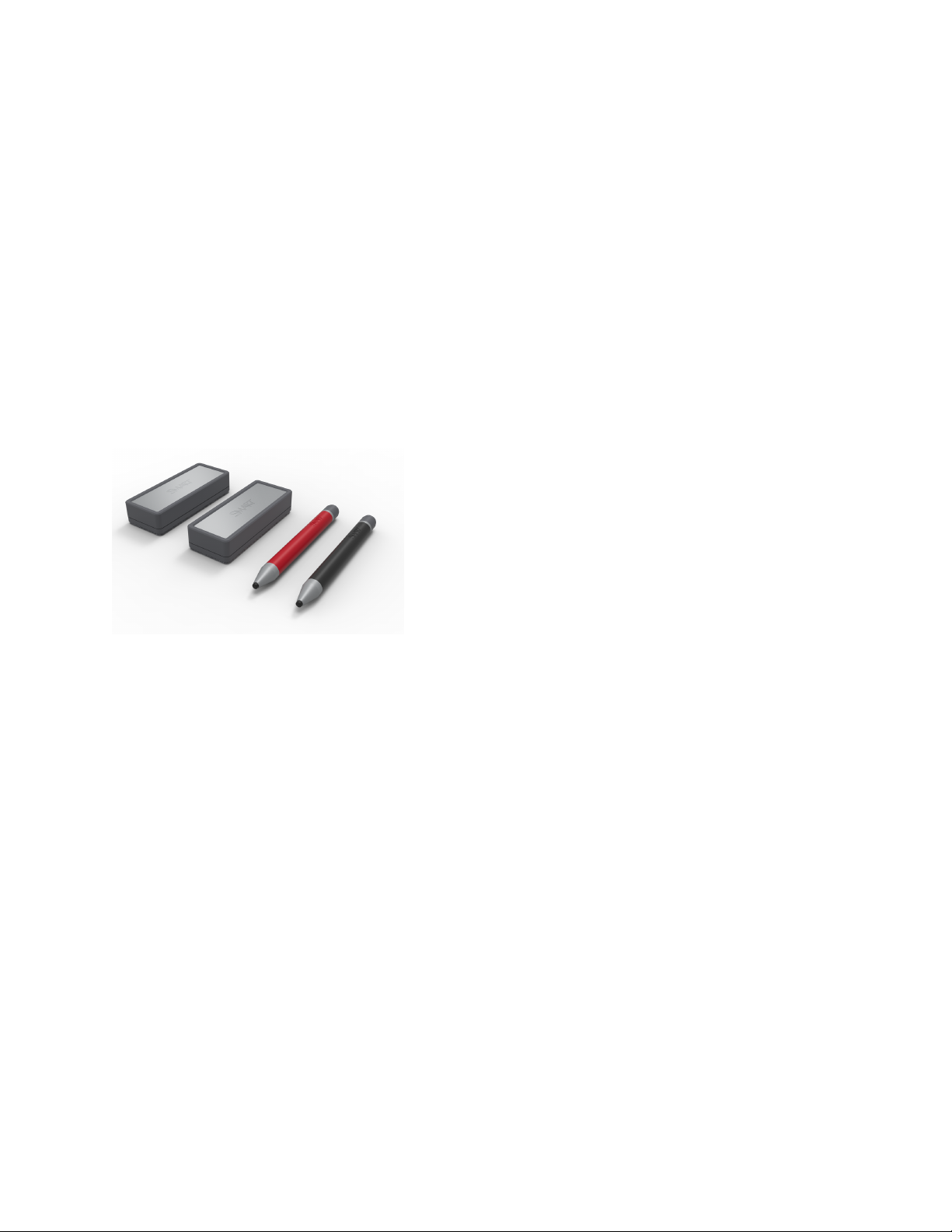
The display comes with a black pen and a red pen that you
can use to write or draw on the screen.
The display also includes two erasers, which you can use to
erase digital ink.
With Object Awareness, the display responds automatically to
the tool or object you’re using, whether it’s a pen, finger,
eraser, or palm. The display’s Pen ID and Simultaneous Tool
Differentiation technologies allow multiple people to write
independently and simultaneously, using different colored ink.
Support for additional pens and tools
The SMART Board 6000S features the Tool Explorer™ platform, which enables you to use other SMART-
authorized pens and tools in addition to those supplied with the display. No additional configuration is
required — just pick up any Tool Explorer-enabled object such as a pen, object, or manipulative and start
using it. For more information about using Tool Explorer-enabled object on the display, see using-the-
toolsense-tools.htm.
For more information about available tool kits, see smarttech.com/accessories.
iQ experience
If enabled, the iQ embedded computer provides one-touch access to collaborative tools, such as a
whiteboard, wireless screen sharing, and a web browser. There’s no need for wires, cables, or manual
software and firmware updates.
smar ttech.com/kb/171414 11
Page 12
Chapter 1
Welcome
NOTE
Some features, such as Browser and Screen Share, require a properly configured network connection.
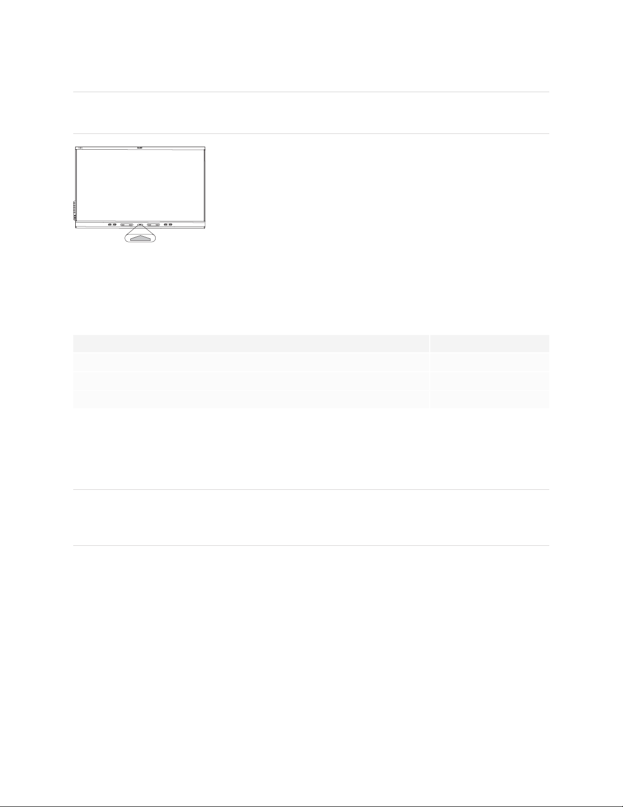
Press the Home button on the display (pictured) or the remote control to
open the Home screen. From the Home screen, you can open the iQ apps,
switch inputs, and adjust settings.
Display
The 4K ultra-high-definition LED display provides optimal image clarity and wide viewing angles.
The size of the display varies by model:
Models Size (diagonal)
SBID-6265S,SBI D-6265S-PW,SBI D-6065S, SBID-6065S-PW 65"
SBID-6275S, SBID-6275S-PW, SBID-6075S,SBI D-6075S-PW 75"
SBID-6286S,SBID-6286S-PW,SBID-6086S,SBI D-6086S-PW 86"
Audio
The display includes two 20 W integrated speakers, which are designed to provide sound at the front of a
room.
TIP
You might want to connect an external audio system if you’re providing sound in a larger space (see
Connecting an external audio system on page36).
Network connectivity
The display requires a network connection for downloading software and firmware updates, and a number
of the iQ apps require a network connection as well.
smar ttech.com/kb/171414 12
Page 13

Chapter 1
Welcome
You can connect to a network using Wi-Fi or an Ethernet cable:
l The Wi-Fi module supports both 2.4 and 5 GHz bands.
l The two RJ45 jacks allow you to connect the display and an external device, such as a computer, to a
Gigabit Ethernet network.
For more information, see Connecting to a network on page27.
Room computers and guest laptops
You can connect room computers and guest laptops to the display and view and interact with their inputs.
The display comes with SMART software that you can install on connected computers to take full
advantage of the display’s features while using the connected computers.
For more information, see Connecting room computers and guest laptops on page32.
Accessory slot
You can install an OPS-compatible device, such as a SMART OPS PC module, in the accessory slot.
SMARTOPS PC modules provide a complete Windows® 10 Pro installation.
For more information on SMART OPS PC modules, see SMART OPS PC module on page17.
CAUTION.
l The accessory slot’s maximum available power is 60 W. The slot is not a limited power source. To
reduce the risk of fire, make sure that accessories connecting to the slot satisfy the fire enclosure
requirements of IEC60950-1 and/or IEC 62368-1.
l Do not install or remove the OPS PC or other devices from the accessory slot while the display is
turned on. Ensure the power switch on the back of the display beside the AC power inlet is in the
OFF (O) position.
NOTE
Unlike with previous SMART Board interactive displays, the SMART Board 6000S and 6000S Pro
interactive displays don’t require an AM30, AM40, or AM50 appliance in the accessory slot. The iQ
experience is embedded on these interactive displays (see iQ experience on page11). For this reason,
SMART doesn’t recommend installing AM30, AM40, or AM50 appliances in these displays’ accessory
slots.
smar ttech.com/kb/171414 13
Page 14
Chapter 1
Welcome
Convenience panel
Proximity sensor
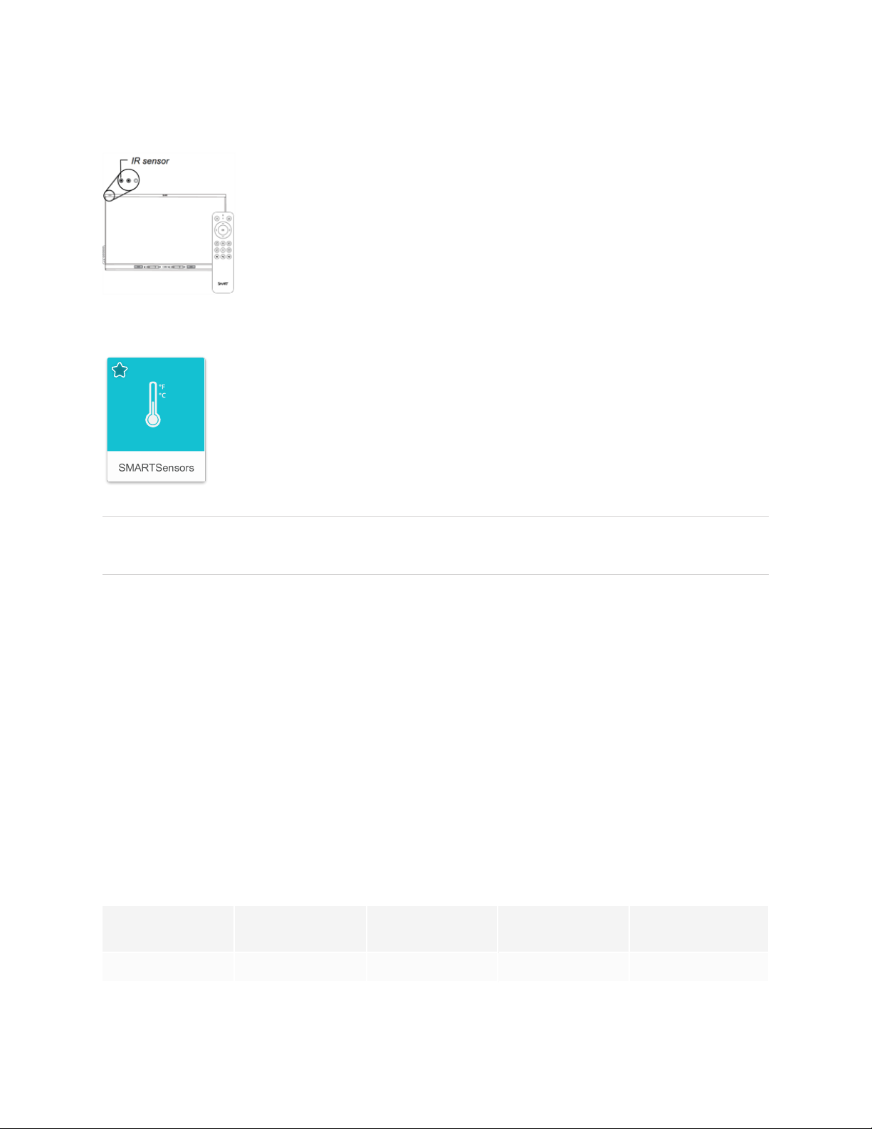
The proximity sensor is located in the top-left corner of the display’s frame.
The proximity sensor can detect people up to 16' (5 m) away when the display is in
Standby mode.
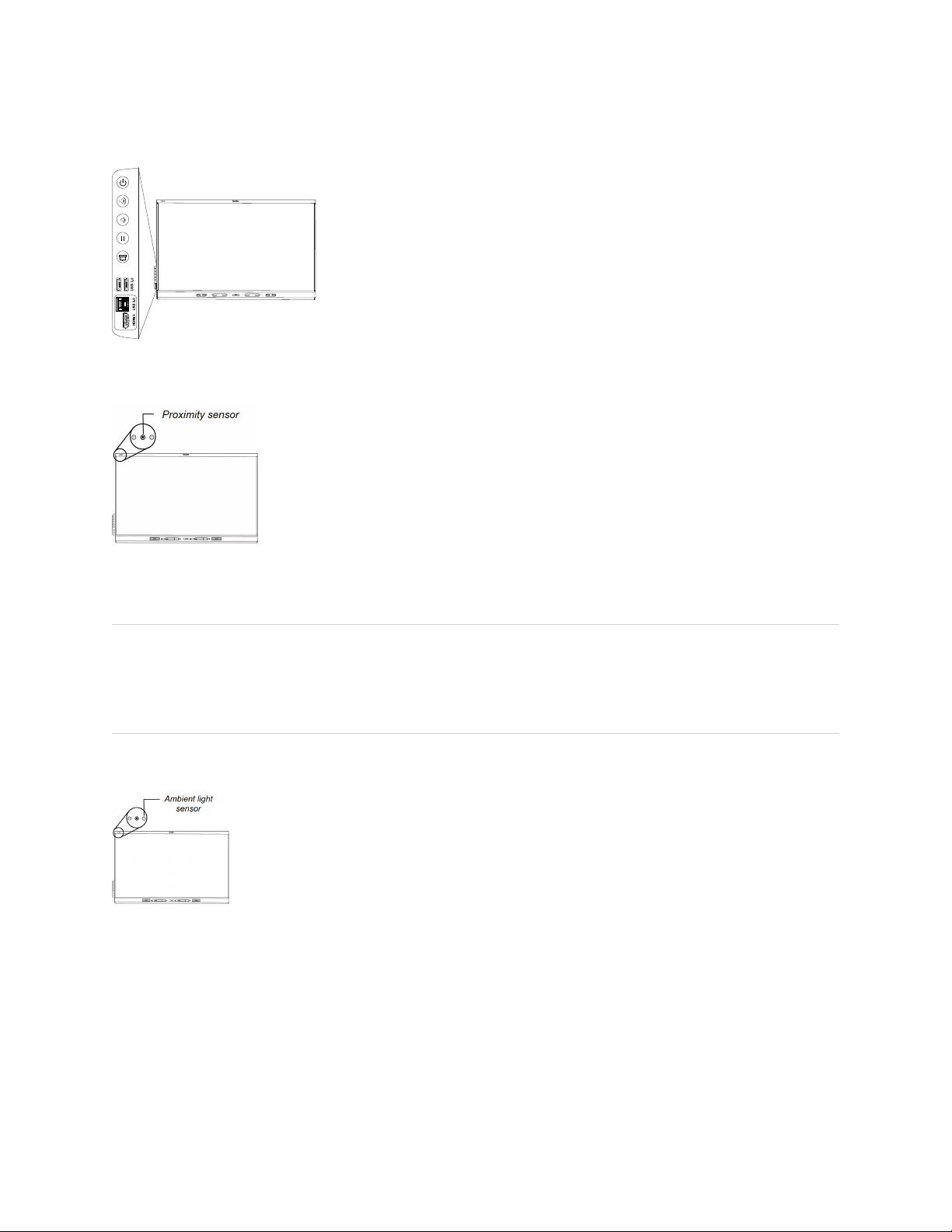
The convenience panel provides buttons for turning the display on and off,
controlling the volume, freezing and unfreezing the screen, and showing
and hiding a screen shade. It also includes connectors for USB peripherals
and a computer or other input source.
When the proximity sensor detects people in the room, the display turns on or
enters ready mode, depending on how its configured.
If the room is empty for a specified period, the display returns to Standby mode.
NOTE
The sensor can detect people through glass. Consider this when finding a location for the display (see
Installing the display on a wall on page21). Don’t position the display so that the sensor is facing a
window.
Ambient light sensor
The ambient light sensor is located in the top left corner of the display’s frame.
The ambient light sensor detects the room’s brightness and adjusts the brightness of the
screen accordingly.
You can enable, disable, and adjust this feature (see Appendix A: Adjusting settings on
page54).
smar ttech.com/kb/171414 14
Page 15
Chapter 1
Welcome
Remote control and IR sensor
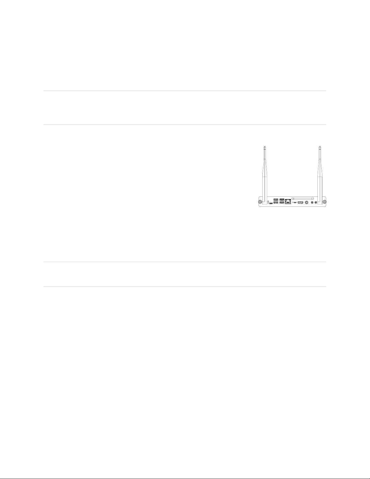
You can use the remote control to turn the display on and off, adjust display settings,
and so on.
The display’s IR sensor is located in the top-left corner of the display’s frame.
Temperature and humidity sensors
The display features integrated temperature and humidity sensors that enable real-time
measurement and recording of the environmental conditions surrounding the display.
This data is easily accessible using the temperature and humidity app in the display’s
App library.
NOTE
Temperature and humidity sensors are available only when iQ is enabled.
Mounting hardware
The display comes with a WM-SBID-200 wall mount, which you can use to mount the display on a wall (see
Installing the display on a wall on page21).
You can also mount the display on a wall or mobile stand (see Accessories on the next page).
Accessory mounting points
The display features M4 mounting points located at the top, bottom, left, and right for SMART approved
accessories.
Identifying your specific model
SMART offers a variety of models of the SMARTBoard 6000S and 6000S Pro series interactive display:
Model Frame style Screen size
(approximate)
iQ embedded
computing
SMARTNotebook®
Player
SBID-6265S White 65" Yes Yes
smar ttech.com/kb/171414 15
Page 16

Chapter 1
Welcome
Model Frame style Screen size
(approximate)
iQ embedded
computing
SMARTNotebook®
Player
SBID-6275S White 75" Yes Yes
SBID-6286S White 86" Yes Yes
SBID-6265S-PW White 65" Yes No
SBID-6275S-PW White 75" Yes No
SBID-6286S-PW White 86" Yes No
SBID-6065S White 65" No No
SBID-6075S White 75" No No
SBID-6086S White 86" No No
SBID-6065S-PW White 65" No No
SBID-6075S-PW White 75" No No
SBID-6086S-PW White 86" No No
Refer to the specifications for detailed technical information for these models, including product
dimensions and weights (see More information on page18).
Accessories
Accessories for the display include:
l Pen accessory kit
l Tool Explorer-enabled objects and manipulatives
l SMART OPS PC module
l Stands
l USB extenders
NOTE
For more information about these and other accessories, see smarttech.com/accessories.
Pen accessory kit
The pen accessory kit includes blue, green, purple, and orange pens and a holder that you can mount on
the side of the display.
smar ttech.com/kb/171414 16
Page 17
Chapter 1
Welcome
Tool Explorer-enabled objects and manipulatives
The display’s Tool Explorer platform enables you to use a range of different pens, objects, and
manipulatives that are automatically recognized the moment they contact the display’s screen.
NOTE
Support for the different pens, objects, and manipulatives varies depending on the model of display, see
using-the-toolsense-tools.htm.
SMART OPS PC module
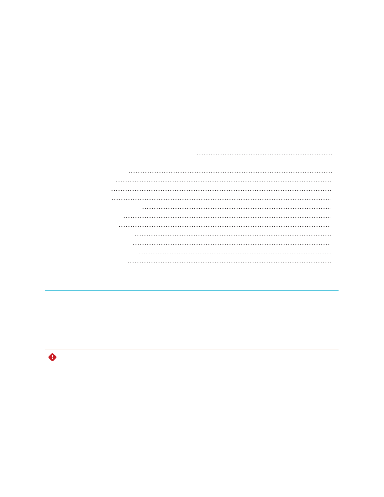
SMART Open Pluggable Specification (OPS) PC modules provide a hassle-free
Windows 10 Pro installation based on eighth generation Intel® Core™ processors
and are designed specifically to work with a SMART display. All OPS PC
modules are WHQL certified and fully licensed with Windows 10 Pro. Install the
OPS PC module in a display’s OPS slot to provide a complete 4K UHD Windows
10 installation at your fingertips, without the need for an external PC or additional
cables.
Install familiar Windows applications, such as SMARTNotebook®,
SMARTTeamWorks™, and SMARTMeetingPro® software, and access the internet directly through your
display’s network connection. Upgrades and service for the OPS PC module are easy to perform without
removing the display from its mounting.
NOTE
Refer to an application’s specifications for information about its computer requirements.
Stands
If you want to move the display from place to place, you can install it on a SMART mobile stand. If you are
installing the display on a wall that cannot support the display’s full weight, you can install the display on a
SMART floor stand.
smar ttech.com/kb/171414 17
Page 18

Chapter 1
Welcome
USB extenders
As noted in the display’s specifications, there is a maximum length for USB cable connections between the
display and computer.
When using USB 2.0, the cable should be no longer than 16'(5m).
When using USB 3.0, the cable should be no longer than 9'(3m).
Use one of the following USB extenders if you need a longer USB connection:
Extender Specifications
USB-XT smarttech.com/kb/119318
CAT5-XT-1100 smarttech.com/kb/170202
NOTE
For more information about extending USB connections, see USB cable extenders.
More information
SMART provides a variety of other documents for this display in the Support section of the SMART website
(smarttech.com/support). Scan the QR code on the cover of this guide to view links to SMARTBoard 6000S
and 6000S Pro series interactive display documents and other support resources.
smar ttech.com/kb/171414 18
Page 19
Chapter 2
Moving the display to the installation site 19
Using transportation aides 20
Accommodating doorways, hallways, and elevators 20
Dealing with cracked, chipped, or shattered glass 21
Saving the original packaging 21
Installing the display on a wall 21
Choosing a location 22
Choosing a height 24
Assessing the wall 24
Selecting mounting hardware 24
Selecting a wall mount 24
Mounting the display 25
Mounting multiple displays 25
Installing the display on a stand 26
Using SMART mobile stands 26
Using a third-party stand 26
Connecting to a network 27
Connecting power and turning on the display for the first time 27
SMART recommends that only trained installers install the display.
This chapter is for installers. Installers should read this information along with the installation instructions
included with the display before they begin the installation.
WARNING
Improper installation of the display can result in injury and product damage.
Moving the display to the installation site
After your organization receives the display, you need to move it to the place where you plan to install it.
On occasion, you might also need to move the display to another location after initially installingit.
smar ttech.com/kb/171414 19
Page 20

Chapter 2
Installing the display
IMPORTANT
l Move the display at your own risk. SMART cannot accept liability for damages or injury that occur
during the display’s transportation.
l When moving the display:
o
Follow local safety regulations and standards.
o
Pack the display in its original packaging, including the pallet.
o
Move the display so that its top frame faces up.
o
Have at least two people move the display.
TIP
Display packaging may be labeled to indicate which side is the front. Look for “FRONT” on the packaging
to help orient the box during transportation.
Using transportation aides
You can use the following aides to move the display:
l Cart
l Furniture dolly
l Mechanical lift
Accommodating doorways, hallways, and elevators
In some situations, you might need to remove the display from its packaging to move it through narrow
doorways or hallways or onto an elevator. In these situations, keep the foam pieces on the bottom corners
of the display. These foam pieces protect the display if you need to set it down during transportation.
You might also need to rotate the display so that its top frame faces to the side. You can do this during
transportation, but when you install the display, it must be in landscape orientation (with the top frame
facing up).
smar ttech.com/kb/171414 20
Page 21
Chapter 2
Installing the display
Dealing with cracked, chipped, or shattered glass
The display contains safety-tempered glass. Although this glass is heat-strengthened to help withstand
impacts, the glass can crack, chip or shatter if struck with enough force. (Safety glass is designed to break
into small pieces rather than sharp shards if it is broken.) Temperature changes can cause a minor crack or
chip to become worse, possibly causing the glass to shatter. See the knowledge base article, Shattered
glass on an interactive display, for information about conditions that can cause the display’s glass to shatter
even when it’s not in use.
If the display’s glass is cracked or chipped, have it professionally inspected and repaired at a SMART
authorized repair center. If the display’s glass shatters, carefully clean up the area and have the display
repaired or replaced.
WARNING
For safety and to prevent further damage, do not continue to install or use the display if its glass is
cracked, chipped or shattered.
Saving the original packaging
Save the original packaging and repack the display with as much of it as possible if you ever need to move
the display after installation. This packaging was designed to provide the best possible protection against
shock and vibration.
NOTE
If the original packaging isn’t available, you can purchase the same packaging directly from your
authorized SMART reseller (smarttech.com/where).
CAUTION
Move the display only in the original packaging or replacement packaging purchased from your
authorized SMART reseller. Moving the display without correct packaging can lead to product damage
and voids the warranty.
Installing the display on a wall
Typically, you install the display on a wall in a classroom or meeting space.
smar ttech.com/kb/171414 21
Page 22

Chapter 2
Installing the display
Choosing a location
A display is typically installed at the room’s focal point, such as at the front of a classroom or meeting
space.
Selecting an appropriate location for the display is crucial for ensuring the best possible experience with
the product. Consider the following factors as you choose a location:
Factor Considerations
Room setup
Power and other
connections
The location allows users, including those in wheelchairs, access to the display.
l
Refer to local regulations regarding accessibility.
The location allows for multiple users to access the display at the same time.
l
The location accommodates room traffic patterns, and there are no tripping
l
hazards.
The display is not installed where it could be hit by a door or gate.
l
There are no nearby heat sources directed at the display, such as a radiator or
l
heat vent.
There are no nearby shelving units, desks, or other furniture that has doors or
l
drawers that could hit the display.
Furniture, wall décor, and other room features, such as light switches and
l
thermostats, do not block the display and are not blocked by it. (You might be
able to move some of these room features to accommodate the display.)
The location is close to:
l
o
A power outlet
o
A network outlet (if you plan to use a wired network connection)
o
A room computer (if you plan to connect a room computer)
o
External audio systems and other devices that you want to connect to the
display
NOTES
o
If the location is not near a power outlet, consult an electrician for the
power setup you need.
o
Determine if you’ll need additional equipment, such as power bars,
additional cables, or cable extenders.
The location is not where the mains power supply enters the building.
l
smar ttech.com/kb/171414 22
Page 23
Chapter 2
Installing the display
Factor Considerations
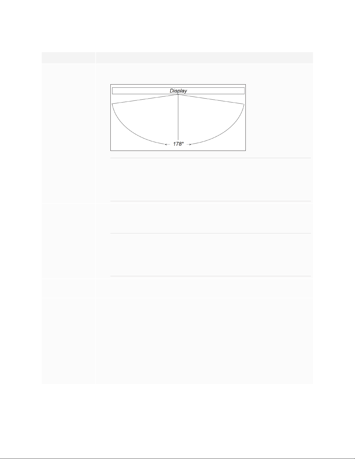
Visibility The display’s screen is clearly visible to all users in the room. SMART
recommends users sit within a 178° viewing area:
NOTE
The viewing area depends on the display’s resolution and a variety of other
factors. For more information, see the knowledge base article,
Recommended viewing distances and viewing angles for SMARTBoard
interactive displays.
Lighting The location is not near bright light sources, such as windows or strong
overhead lighting.
Light sources can cause glare on the display’s screen, reducing its visibility.
TIP
To reduce light interference, install blinds or shades on windows or skylights
and install switches to dim or turn off any lights shining directly on the
display’s screen. Keep in mind that sunlight can come through windows at
different angles at different times of the year.
Acoustics The room has good acoustics (see Configuring your SMARTBoard 6000S for
the best audio performance).
Environment and
ventilation
The location meets the environmental requirements in the display’s
l
specifications (see More information on page18).
The display isn’t subjected to strong vibrations or dust.
l
Ventilation systems don’t blow air directly on the display.
l
There is adequate ventilation or air conditioning around the display so that heat
l
can flow away from it and the mounting equipment. SMARTrecommends at
least 2" (5 cm) of space on all sides of the display for proper airflow.
If you plan to install the display in a recessed area, there is at least 4"(10cm) of
l
space between the display and the recessed walls to enable ventilation and
cooling.
smar ttech.com/kb/171414 23
Page 24
Chapter 2
Installing the display
Choosing a height
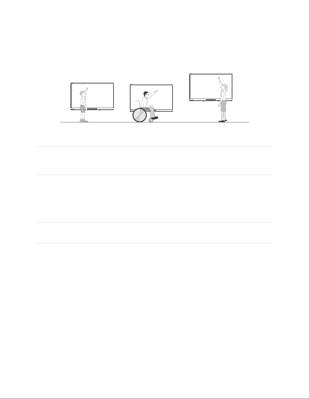
Consider the general height of the user community when you choose the height for the display.
SMART recommends that you mount the display so that its top is 6'5" (1.9m) from the floor.
NOTE
If participants will be sitting at a steep angle (such as in a lecture hall), you may have to adjust the
installation height or angle.
Assessing the wall
Be sure the wall you’re installing the display on can support the weight of the display and mounting
equipment. If it can’t, consider using a SMART wall stand to transfer some of the weight from the wall to the
floor (see smarttech.com/accessories).
NOTE
Refer to the display’s specifications for its weight (see More information on page18).
In some situations, you may need to request an engineering analysis to determine if the wall can support
the display.
Selecting mounting hardware
The mounting hardware required for installation varies according to the type of wall onto which the display
is being mounted.
Refer to Installation best practices for SMART products (smarttech.com/kb/171035) for the mounting
hardware required for the display.
Selecting a wall mount
It is always best to mount the display on a wall. If the wall can’t support the display’s weight, you can use
additional hardware to transfer some of the weight to the floor.
smar ttech.com/kb/171414 24
Page 25
Chapter 2
Installing the display
The display comes with a WM-SBID-200 wall mount. SMART recommends using this wall mount to install
the display on a wall.
If you choose a third-party option rather than one of SMART’s mounting options, be sure the wall mount can
accommodate the display’s dimensions and support the display’s weight as well as the weight of any
attached accessories.
Mounting the display
Mount the display following the included installation instructions. In addition, consider the following:
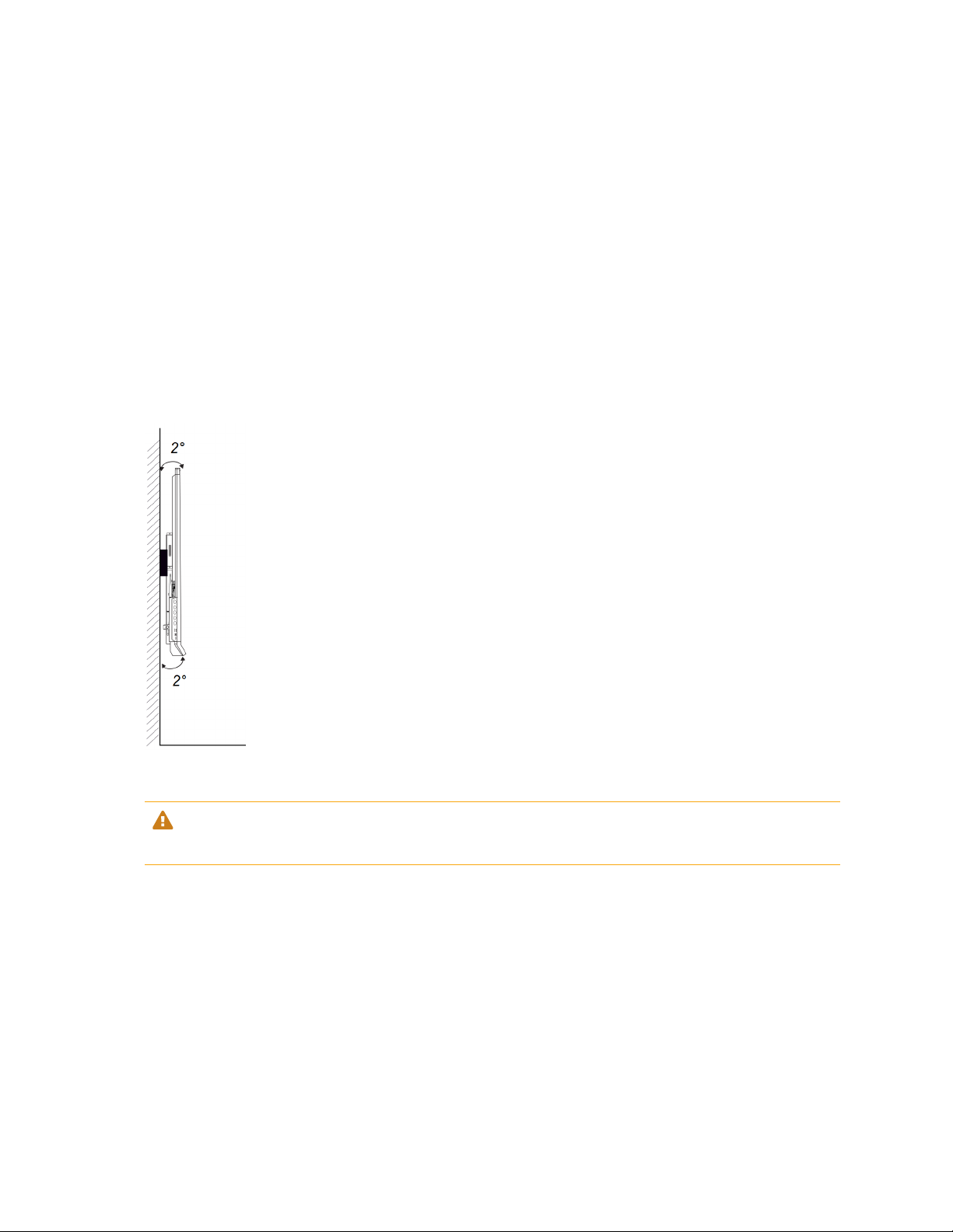
l Mount the display vertically (90° relative to the floor plus or minus 2° for tolerance) and in landscape
orientation. SMART doesn’t support mounting the display at other angles or in portrait orientation.
l Use M8 bolts included with the wall mount to fasten the bracket.
CAUTION
Do not over-tighten the bolts. Use 97.36–177.01 in-lb. (11–20 N·m) fasten force.
l Because the display’s receptacles might not be easily accessible after you mount the display,
consider connecting cables for power, room computer and other devices while the display is still in its
packaging (see Chapter 3: Connecting computers and other devices on page30).
Mounting multiple displays
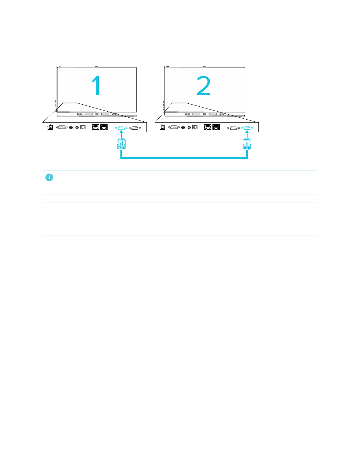
If you mount multiple displays side by side, you can connect them with RS-232 cables to turn on, turn off,
and otherwise operate all of the displays from the first display’s convenience panel.
smar ttech.com/kb/171414 25
Page 26
Chapter 2
Installing the display
The leftmost display (when viewed from the front) is the first display:
IMPORTANT
Use only standard RS-232 cables. Do not use null modem cables.
NOTE
For more information about using RS-232 cables for remote management, see Appendix C: Managing
the display using RS-232 on page67.
Installing the display on a stand
If you want to move the display from place to place or if it’s not possible to install the display on a wall, you
can install it on a stand.
Using SMART mobile stands
SMART mobile stands are designed for SMART interactive displays. They are height-adjustable. Some
models include integrated speakers, a locking cabinet to secure equipment, and casters that swivel and
lock for easy movement.
For more information about SMART mobile stands, see smarttech.com/accessories.
Using a third-party stand
For information on selecting and using a third-party stand, see Installing your SMARTBoard 6000S on a
stand.
smar ttech.com/kb/171414 26
Page 27
Chapter 2
Installing the display
Connecting to a network
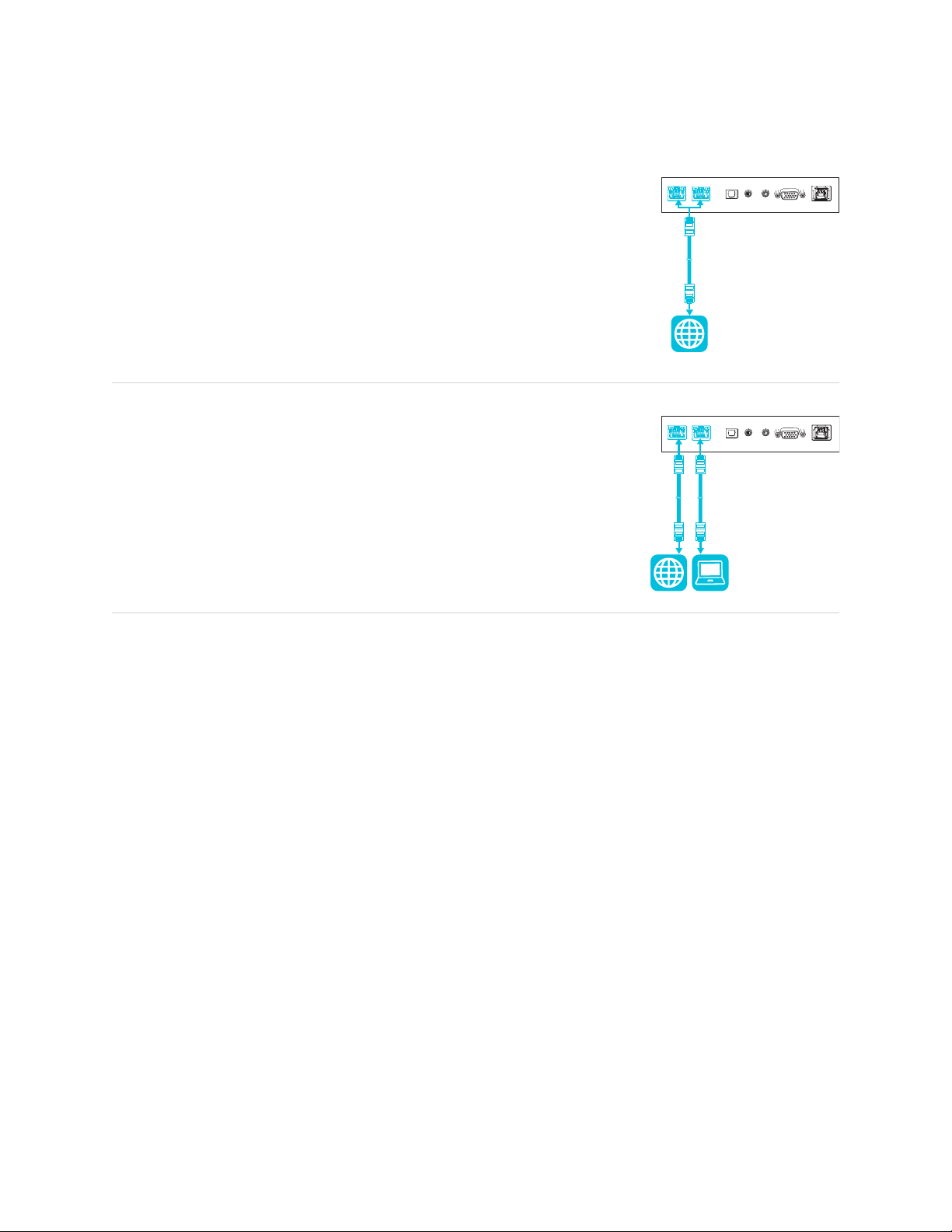
The display requires a network and internet connection for downloading
software and firmware updates, and a number of the iQ apps require a network
connection as well. You can connect to a network using Wi-Fi or one of the
RJ45 jacks.
TIP
If you’re using one of the display’s RJ45 jacks to connect to a network, you
can connect a computer to the other RJ45 jack to provide network access
for the computer (pictured). This is particularly useful if there is only one
wired network connection in the room. (Network access is available when
the display is on or in Standby mode but not when it’s in Power Save mode.)
For more information about the display’s network connection and configuration, see Connecting a SMART
display with the iQ experience to a network.
Connecting power and turning on the display for the first time
The final step in installing and configuring the display is to connect power and turn it on. When you first turn
on the display, a setup wizard appears. Follow the steps in the wizard to complete the setup.
smar ttech.com/kb/171414 27
Page 28
Chapter 2
Installing the display
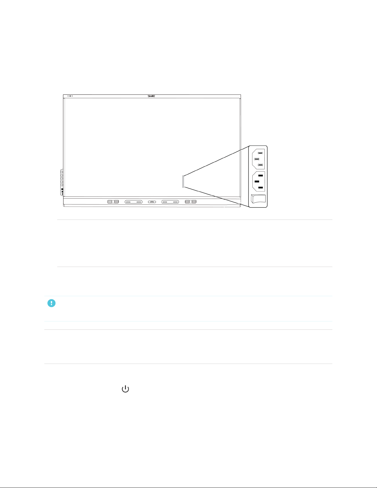
To connect the display to power
Connect the supplied power cable from the AC power inlet on the back of the display to a power
outlet.
NOTES
o
Refer to the display’s specifications for power requirements and power consumption
information (see More information on page18).
o
The AC power output on the back of the display is rated at 250 W.
To turn on and set up the display for the first time
IMPORTANT
Install the OPSPC module before you turn the display on.
NOTE
If a USB drive is connected to the display’s service port, do not remove the USB drive. The USB drive
contains an important firmware update.
1. Flick the switch beside the AC power inlet to the ON(I) position.
Press the Power button on the front control panel or remote control
2.
3. Select your preferred language, and then tap Next.
4. Select your country, and then tap Next.
5. Select your time zone, and then tap Next.
smar ttech.com/kb/171414 28
Page 29

Chapter 2
Installing the display
6. Set the date, and then tap Next.
7. Set the time, and then tap Next.
8. Name the display, and then tap Next.
9. If the display isn’t using a wired network connection, select a wireless network, and then tap Next.
IMPORTANT
The display needs an internet connection for downloading and installing important updates. Ask the
network administrator to confirm that the network has been correctly configured for the iQ
experience. For more information about network configuration, see Connecting a SMART display
with the iQ experience to a network.
NOTE
If an internet connection is not available for downloading and installing important updates, see
Updating system software manually on page46.
10. Select the apps you want to appear in the Apps Library, and then tap Next.
TIP
To change which apps appear in the Apps Library, see Launcher on page56.
11. Tap Finish.
The Welcome screen appears.
smar ttech.com/kb/171414 29
Page 30

Chapter 3
devices
Installing SMART software 31
Connecting room computers and guest laptops 32
Viewing a connected computer’s input 32
Setting a connected computer’s resolution and refresh rate 33
Using recommended cables 34
Connecting USB drives, peripherals, and other devices 34
Troubleshooting connected computers 34
Connecting a SMART OPS PC module 35
Connecting other devices 35
Connecting USB drives, peripherals, and other devices 35
Connecting an external display 36
Connecting an external audio system 36
Connecting room control systems 37
Connector diagrams 37
Connector panel 37
Convenience panel 39
WARNING
Ensure that any cables that cross the floor to the display are properly bundled and marked to avoid a trip
hazard.
smar ttech.com/kb/171414 30
Page 31

Chapter 3
Connecting computers and other devices
Installing SMART software
The display comes with the following software, which you can install on connected computers:
Software Description Notes
SMART Learning Suite A suite of desktop and online software that
combines lesson delivery, activities,
assessments, and collaborative workspaces.
Includes SMARTNotebook software and
SMARTLearningSuite Online.
SMART TeamWorks
roomedition
SMART Meeting Pro Software that enables you to capture ideas in
SMART Product Drivers Software that enables the computer to detect
SMARTInk Software that enables you to write and draw in
SMART Remote
Management
Software that simplifies meetings and
facilitates deeper, more natural interaction
with on-site and remote participants.
a virtually unlimited interactive workspace.
input from the display.
digital ink over applications, files, folders,
websites, and any other open window.
Cloud-based mobile device management
software for remotely maintaining, supporting,
controlling, and securing the display and your
other devices.
Education models only.
SMARTNotebook basic
version also available.
Pro models only.
Pro models only.
Included with
SMARTLearningSuite,
SMARTTeamWorks, and
SMARTMeetingPro software
Included with
SMARTLearningSuite,
SMARTTeamWorks, and
SMARTMeetingPro software
N/A
TIP
You can purchase additional licenses or subscriptions to SMART software to install on other computers.
Contact your authorized SMART reseller (smarttech.com/where) for information about purchasing SMART
software.
You can download SMART software from smarttech.com/downloads and install it following the instructions
in Installing and maintaining SMARTNotebook, Downloading and installing SMARTTeamWorks, or
Installing and maintaining SMARTMeetingPro.
smar ttech.com/kb/171414 31
Page 32
Chapter 3
Connecting computers and other devices
Connecting room computers and guest laptops
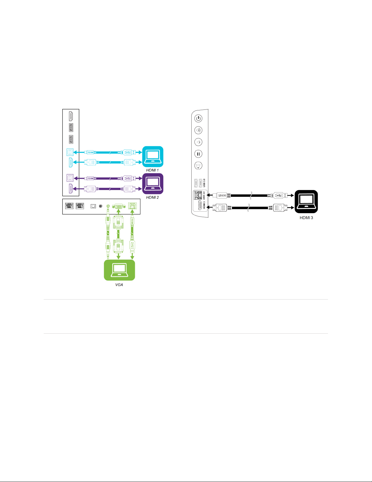
You can connect cables for room computers and guest laptops. By installing cables in advance, you make
use of connectors that might not be accessible after the display is mounted on the wall. You can then run
the cables across floors or behind walls as needed.
Connector panel Convenience panel
NOTE
Install SMART software on computers you connect to the display (see Installing SMART software on the
previous page).
Viewing a connected computer’s input
Use the Input app to view a connected computer’s input on the display.
smar ttech.com/kb/171414 32
Page 33
Chapter 3
Connecting computers and other devices
To view a connected computer’s input
1. Connect the computer to the display.
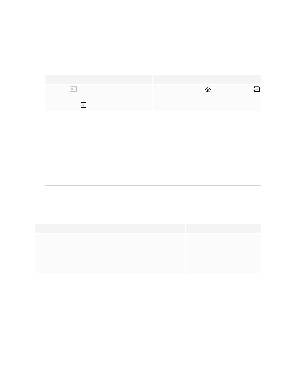
2. Do one of the following:
If iQ is enabled If iQ is disabled
Tap Input on the Home screen.
OR
Press the Home button or the Input button
on the remote control.
Press the Input on the remote control.
The display shows thumbnails of the devices that are connected to the display:
o
A gray thumbnail indicates no device is connected to an input.
o
A blue thumbnail indicates a device is connected to an input but is in Sleep mode.
o
A thumbnail showing a preview screen indicates an active device is connected to an input.
TIP
If iQ is disabled and you want a computer’s input to appear whenever you wake up the display, tap
the star in the upper-left corner of the computer’s thumbnail.
3. Tap the computer’s thumbnail.
Setting a connected computer’s resolution and refresh rate
This table presents the recommend resolutions and refresh rates for the display’s inputs:
Input source Resolution Refresh rate
HDMI 1 3840×2160 60Hz
HDMI 2 3840×2160 60Hz
HDMI 3 3840×2160 60Hz
VGA 1920×1080 60Hz
If possible, set connected computers to these resolutions and refresh rates. See the computers’ operating
system documentation for instructions.
smar ttech.com/kb/171414 33
Page 34

Chapter 3
Connecting computers and other devices
Using recommended cables
SMART recommends the following varieties of cable:
Cable type Maximum length Recommendation
HDMI 23' (7 m)
VGA 23' (7 m) Use VGA cables with all pins in their connectors fully
Stereo 3.5 mm 20' (6 m) [N/A]
USB 2.0 16' (5 m) Use a USB extender if the distance between the
USB 3.0 9' (3 m) SMART supports only installations that use directly
1
Use only certified premium high-speed HDMI cables that
have been tested to support the performance standard
you require.
populated and wired.
computer and the display is greater than 16' (5 m). For
more information, see USB extenders on page18.
USB2.0 cables support Hi-Speed (480Mbps), whether
connected to a USB 2.0 or USB 3.0 receptacle. For
SuperSpeed (5Gbps), connect a USB 3.0 cable to a USB
3.0 receptacle.
connected video and USB cables, AC-powered
extenders, or USB extenders purchased from SMART.
You might be able to use higher-grade cables that are
longer than specified. If you have problems with such a
cable or an extender of any type, test the connection
with a shorter cable before contacting SMART Support.
Using cables that exceed these maximum lengths may produce unexpected results, degraded picture
quality or degraded USB connectivity.
Connecting USB drives, peripherals, and other devices
You can use USB drives, peripherals, and other devices with a computer connected to the display using the
display’s USB plugs.
For more information, see Connecting USB drives, peripherals, and other devices on the next page.
Troubleshooting connected computers
For troubleshooting information for connected computers, see Chapter 5: Troubleshooting on page47.
1
The performance of cables longer than 23' (7 m) is highly dependent on the cable’s quality.
smar ttech.com/kb/171414 34
Page 35
Chapter 3
Connecting computers and other devices
Connecting a SMART OPS PC module
If your organization has purchased a SMART OPS PC module, you or your
organization’s installers can install the OPS PC module in the display’s accessory
slot following the OPS PC module’s installation instructions
(smarttech.com/kb/171544). You can then view the OPS PC module’s input on
the display.
For more information about SMART OPS PC modules, see the SMART OPS PC
modules user guide (smarttech.com/kb/171747).
Connecting other devices
In addition to computers, you can connect the following devices to the display:
l USB drives, peripherals, and other devices
l External displays
l External audio systems
l Room control systems
Connecting USB drives, peripherals, and other devices
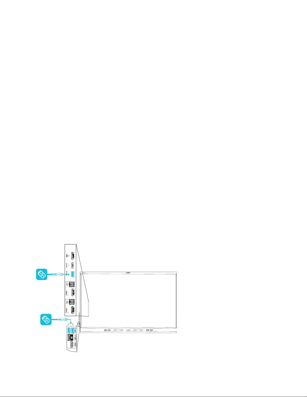
The display includes two USB 3.0 Type-A plugs on the convenience panel and one USB 3.0 Type-A plug
on the connector panel. You can connect USB drives, peripherals (such as keyboards), and other devices to
these connectors and use the devices with the iQ experience, connected computers, and devices installed
in the accessory slot (such as the SMART OPS PC).
smar ttech.com/kb/171414 35
Page 36
Chapter 3
Connecting computers and other devices
Connecting an external display
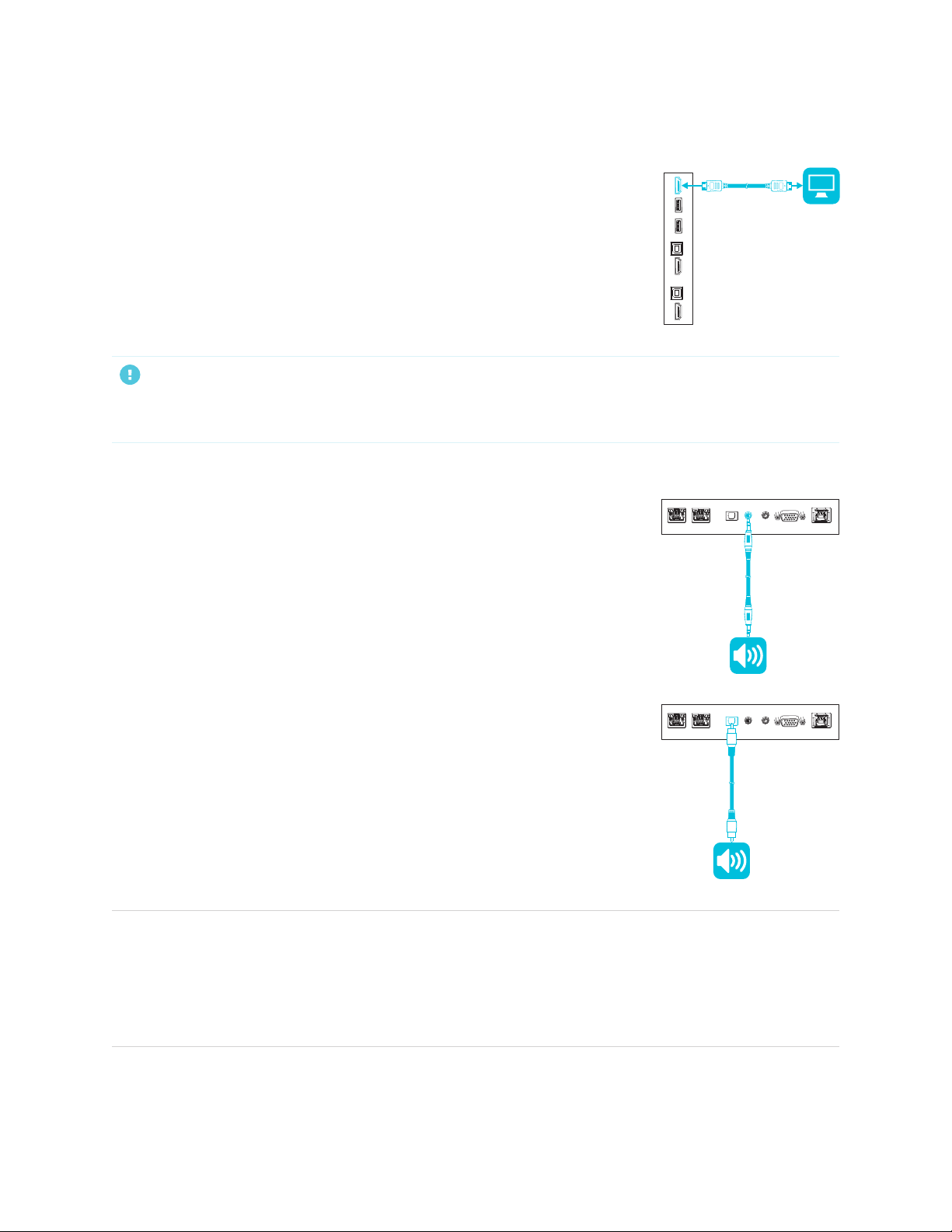
You can connect an external display using the HDMI 2.0 out connector on the
connector panel (pictured). The external display will show the same image. This
is useful when you’re using the display in an auditorium or other large space
where it would be beneficial to have a second display.
IMPORTANT
If the connected external display doesn’t support HDCP, the image on the external display is limited to
480p resolution. For full resolution output, connect a display that supports HDCP.
Connecting an external audio system
The display includes two speakers, which are designed to provide sound at the
front of a room. You might want to connect an external audio system if you’re
providing sound in a larger space.
You can connect an external audio system to the display using the stereo
3.5mm out connector (pictured). This disables the display’s internal speakers.
Alternatively, you can connect an external audio system directly to a room
computer.
In addition to the stereo 3.5 mm out connector, the display provides a
Sony/Philips Digital Interface (S/PDIF) out connector (pictured). S/PDIF is a
digital audio transmission medium. You need an audio system that has an
S/PDIF input to decode this connection to analog. Most external sound bars
include a S/PDIF connector.
NOTES
l If you connect an external speaker system to the display using the Sony/Philips Digital Interface
(S/PDIF) out connector and the audio source device is connected to the display using an HDMI 2.0
connection, the external speaker system must support HDCP 2.2. For more information, see SMART
Board interactive flat panels and High-bandwidth Digital Content Protection (HDCP).
smar ttech.com/kb/171414 36
Page 37
Chapter 3
Connecting computers and other devices
l The S/PDIF audio is a fixed-volume output. Adjusting the display’s volume for its internal speakers
does not affect the volume output of the S/PDIF port.
Connecting room control systems
A room control system enables users to control a room’s lighting, audio system and, possibly, the display.
Some installations may require you to integrate the display with a room control system.
You can use the display’s RS-232 connector to connect a third-party external control system to the display
(see Appendix C: Managing the display using RS-232 on page67).
NOTE
Displays are not compatible with centralized remote control systems, such as a universal remote control.
Connector diagrams
Connector panel
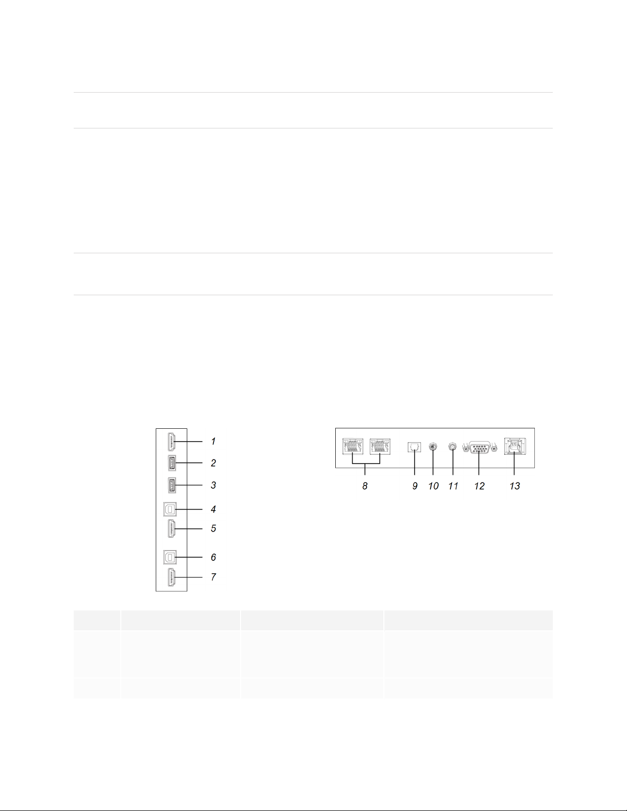
The following diagram and table present the connectors on the display’s connector panel:
Side Bottom
No. Connector Connects to Notes
1 HDMI 2.0 out External display See Connecting an external
display on the previous page and
HDMI cables and connectors.
2 USB 2.0 Type-A [N/A] This connector is a service port.
smar ttech.com/kb/171414 37
Page 38

Chapter 3
Connecting computers and other devices
No. Connector Connects to Notes
3 USB 3.0 Type-A Supported USB drives,
peripherals, and other
devices
See Connecting USB drives,
peripherals, and other devices on
page35 and USB cables and
connectors.
4 USB 3.0 Type-B HDMI 1 input (touch) See page32 and USB cables and
connectors.
5 HDMI 2.0 in HDMI 1 input (videoandaudio) See page32 and HDMI cables and
connectors.
6 USB 3.0 Type-B HDMI 2 input (touch) See page32 and USB cables and
connectors.
7 HDMI 2.0 in HDMI 2 input
(videoandaudio)
See page32 and HDMI cables and
connectors.
8 RJ45 (×2) Network See page27 and Ethernet
(network) cables and connectors.
9 S/PDIF out Digital audio output See page36 and Digital audio
cables and connectors.
10 Stereo 3.5 mm out External audio system See page36 and Analog audio
cables and connectors.
11 Stereo 3.5 mm in VGA input (audio) See page32 and Analog audio
cables and connectors.
12 VGA in VGA input (video) See page32 and VGA cables and
connectors.
13 USB 3.0 Type-B VGA input (touch) See page32 and USB cables and
connectors.
smar ttech.com/kb/171414 38
Page 39
Chapter 3
Connecting computers and other devices
Convenience panel
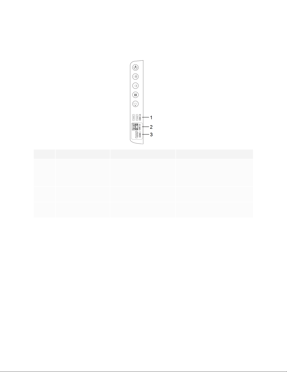
The following diagram and table present the connectors on the display’s convenience panel:
No. Connector Connects to Notes
1 USB 3.0 Type-A (×2) Supported USB drives,
peripherals, and other
devices
See Connecting USB drives,
peripherals, and other devices on
page35 and USB cables and
connectors.
2 USB 3.0 Type-B HDMI 3 input (touch) See page32 and USB cables and
connectors.
3 HDMI 2.0 in HDMI 3 input
(videoandaudio)
See page32 and HDMI cables and
connectors.
smar ttech.com/kb/171414 39
Page 40

Chapter 4
Turning off, turning on, and resetting the display 40
Cleaning and maintaining hardware 41
Checking the display installation 41
Cleaning the screen 41
Cleaning the touch sensors 42
Cleaning Tool Explorer-enabled tools and manipulatives 42
Maintaining ventilation 43
Preventing condensation 43
Replacing the pens and erasers 44
Removing and transporting the display 44
Updating system software 45
Applying an automatic system software update manually 45
Updating system software manually 46
With proper maintenance, the display will provide years of use.
Turning off, turning on, and resetting the display
In most situations, you can put the display to sleep when not using it following the instructions in the
SMARTBoard 6000S and 6000S Pro series interactive displays user guide (smarttech.com/kb/171415).
In some situations, such as when you transport the display or clean its screen, you need to turn the display
off. You can turn it back on after.
You can also reset the display.
To turn the display off
Press the Power button on the convenience panel or the remote control for five seconds.
1.
A slider appears on the screen.
smar ttech.com/kb/171414 40
Page 41
Chapter 4
Maintaining the display
2. Move the slider to the right.
3. Flick the switch beside the AC power inlet to the OFF(O) position.
NOTE
Wait at least 30 seconds before turning the display back on.
To turn the display back on
1. Flick the switch beside the AC power inlet to the ON(I) position.
Press the Power button on the convenience panel or the remote control.
2.
To reset the display
Press and hold the Power button on the convenience panel or the remote control for 10 seconds.
The display resets.
Cleaning and maintaining hardware
Checking the display installation
Inspect the display installation frequently to ensure that the display remains securely installed.
l Check the mounting location for signs of damage or weakness that can occur over time.
l Check for loose screws, gaps, distortions, or other issues that could occur with the mounting hardware.
If you find an issue, contact a trained installer.
Cleaning the screen
Follow these instructions to clean the screen without damaging its anti-glare coating or other product
components.
CAUTION
l Do not use permanent or dry-erase markers on the screen. If dry-erase markers are used on the
screen, remove the ink as soon as possible with a lint-free, non-abrasive cloth.
l Do not rub the screen with dense or rough material.
l Do not apply pressure to the screen.
smar ttech.com/kb/171414 41
Page 42
Chapter 4
Maintaining the display
l Do not use cleaning solutions or glass cleaners on the screen, because they can deteriorate or
discolor the screen.
To clean the screen
1. Turn off the display (see Turning off, turning on, and resetting the display on page40).
2. Wipe the screen with a lint-free, non-abrasive cloth.
NOTE
You can also use a damp cloth with a drop of dish soap.
Cleaning the touch sensors
The display uses infrared (IR) transmitters and sensors around the display’s perimeter between the screen
and the frame. Dust buildup on the protective plastic can impair touch performance. Inspect these areas for
dust and clean them every week.
CAUTION
l Do not use compressed air to clean the sensors or borders.
l Do not use water or cleaning agents to clean the touch sensors.
l Do not apply too much pressure when cleaning the display because you can damage the plastic
To clean the IR transmitters and sensors
1. With a clean lint-free, non-abrasive cloth, gently wipe the plastic between the screen and the frame
around the perimeter of the display’s screen.
2. If dirt still remains, use 50% isopropyl alcohol (IPA) to clean the protective plastic between the
screen and the frame.
Cleaning Tool Explorer-enabled tools and manipulatives
Follow these instructions to clean the Tool Explorer-enabled pens, objects, and manipulatives.
CAUTION
l Do not remove any of the labels from the tools or manipulatives.
l Do not submerge the tools or manipulatives in cleaning solutions or water.
smar ttech.com/kb/171414 42
Page 43

Chapter 4
Maintaining the display
To clean the Tool Explorer-enabled tools and manipulatives
1. With a clean lint-free, non-abrasive cloth, gently wipe the surface of the tool or manipulative.
2. If dirt still remains, clean the surfaces of the tool or manipulative using 70-90% isopropyl alcohol (IPA)
or a solution of 10 parts distilled water to one part standard household bleach (5% sodium
hypochlorite). Use a spray bottle to apply the IPA solution to a cloth to avoid over-saturating it.
NOTE
For more information about cleaning SMART accessories, see the SMART knowledge base article,
How to clean SMART Board surfaces and accessories.
Maintaining ventilation
The display requires proper ventilation. Dust buildup in the ventilation holes compromises cooling and can
lead to product failure.
l Clean accessible ventilation holes monthly with a dry cloth.
l Use a vacuum cleaner with a narrow hose end fitting to clear the back ventilation holes regularly. You
might have to remove the display from the wall.
For more information on removing the display, see Removing and transporting the display on the next
page.
CAUTION
Avoid setting up or using the display in an area with excessive levels of dust, humidity, or smoke.
Preventing condensation
If the display has been moved from a cold environment to a warmer one (for example, from storage to the
installation site), let the display sit for a few hours to allow it to acclimate to the new temperature. Failing to
do so can cause humidity to build up in the space between the front glass and the LCD.
If condensation appears under the screen after you turn on the display, select an active video source and
leave the display on for 48 hours. If the condensation doesn’t dissipate, contact SMART Support if the
display is still under warranty.
If there is enough moisture between the layers to cause the moisture to drip and run, remove power
immediately and contact SMART Support if the display is still under warranty.
smar ttech.com/kb/171414 43
Page 44

Chapter 4
Maintaining the display
Replacing the pens and erasers
To prevent damage to the display’s anti-glare coating, replace a pen if its nib or eraser pad become worn.
You can purchase replacement pens and erasers from the Store for SMART Parts
(seesmarttech.com/support/parts-store).
NOTE
For pen and eraser part numbers, refer to the service parts diagrams.
Removing and transporting the display
On occasion, you might need to remove the display from its current wall mount and transport it to another
location.
To remove the display safely, use two or more trained installers.
WARNING
l Do not attempt to move the display by yourself. The display is very heavy.
l Do not move the display by connecting a rope or wire to the handles on the back. The display can
fall and cause injury and product damage.
IMPORTANT
Follow the documentation included with any third-party mounting hardware.
To remove the display
1. Turn off any connected computers.
2. Turn off the display (see Turning off, turning on, and resetting the display on page40).
3. Flick the switch beside the AC power inlet to the OFF(O) position.
4. Remove all accessible cables and connectors.
5. Remove any modules from the accessory slot.
smar ttech.com/kb/171414 44
Page 45

Chapter 4
Maintaining the display
6. Lift the display from its mounting location.
WARNING
Do not place the display on a sloping or unstable cart, stand or table. The display could fall, resulting
in injury and severe product damage.
CAUTION
Do not leave the display face up, face down or upside down for an extended period. This could
cause permanent damage to the screen.
7. Remove the mounting brackets.
To transport the display
See Moving the display to the installation site on page19.
Updating system software
When an update to the system software or firmware is available, the display downloads the update in the
background then waits for four hours of inactivity. When that happens, the display shows a two-minute
countdown before the update begins. The countdown can be interrupted at any time. The display shows a
blank screen for four minutes. When the update is complete, the Whiteboard and its contents appear.
NOTE
You can configure your organization’s network to allow or prevent automatic system software and
firmware updates (see Connecting to a network).
Applying an automatic system software update manually
If the display has downloaded the system software update but hasn’t yet applied the update, you can start
the update process manually from Settings.
To apply an automatic system software update manually
From the Home screen, tap Settings .
1.
2. Scroll to Auto Update.
3. Under Check for Updates Now, tap Apply Update Now.
The display turns off and then turns back on. The display then applies the update.
smar ttech.com/kb/171414 45
Page 46

Chapter 4
Maintaining the display
Updating system software manually
You can download system software updates at smarttech.com/downloads and update your display using a
USB drive.
NOTE
Instructions for downloading and installing system software updates are provided on the software
downloads page.
smar ttech.com/kb/171414 46
Page 47

Chapter 5
The display isn’t turning on 47
The display is turning on when it shouldn’t 48
The screen is blank or there’s a problem with the image on the screen 48
There’s no sound or there’s a problem with the sound 50
Touch isn’t working as expected 50
The pens and erasers aren’t working as expected 51
iQ apps aren’t working as expected 52
SMART software on connected computers isn’t working as expected 52
The SMART OPS PC module isn’t working as expected 52
Contacting your reseller for additional support 52
This chapter explains how to resolve a variety of common issues with the display. If your specific issue isn’t
described here or the solutions to the symptoms don’t work, refer to the SMART knowledge base for
additional troubleshooting information.
https://community.smarttech.com/s/topic/0TOU0000000kAJ0OAM/interactive-
displays?language=en_US&tabset-7ccc8=2
smar ttech.com/kb/171414 47
Page 48

Chapter 5
Troubleshooting
The display isn’t turning on
Symptom Troubleshooting steps
The power light isn’t lit. l Make sure the power cable is securely fastened to the power outlet and the display.
NOTE
If the power cable is connected to a power bar, make sur e the power bar is securely
fastened to the power outlet a nd turned on.
l Make sure the switch beside the AC power inletis in the ON (I) position.
l Make sure the power outlet is working by testing it with a different device.
l Make sure the power cable is wor king by testing it with a different device.
The power light is lit,but the screen is
blank.
l Press the Power button on the convenience panel or the r emote control.
l Make sure the proximity sensors aren’t blocked.
l Restart the display.
See Tur ning off, turning on, and resetting the displayon page40.
l Determine if the problem is with the video.
See The screen is blankor there’s a problem with the image on the screen below.
The display is turning on when it shouldn’t
Symptom Troubleshooting steps
The display turns on or enters Ready
mode when it shouldn’t.
l Checkfor and, if possible,move the display away from the following:
o
Directsunlight
o
Bright lights
o
Forced air ducts
o
Plasma displays
o
Infrared audio systems and other infrared sources
o
Polished floors, glass walls, or other reflectivesurfa ces
l Be awa re that the proximity sensors’ r ange is 16'(5m).
smar ttech.com/kb/171414 48
Page 49

Chapter 5
Troubleshooting
The screen is blank or there’s a problem with the
image on the screen
Symptom Troubleshooting steps
The screen is blank. l Make sure the screen is working by tapping the Home button below the screen
or pressing the Home button on the r emote control to open the H ome screen.
l Make sure any connected computers are on and not in Sleep mode.
l Restart the display and any connectedcomputers.
See Tur ning off, turning on, and resetting the displayon page40.
l Replace the videocables connecting any computers to the display to determine if the
issue is with the cables.
A computer is connected to the
display, but only a connection
message appears on the screen.
The image on the screen is distorted.
OR
There ar e lines, snow or, other visual
noise on the screen.
OR
The image if flickering or flashing.
OR
The image is dim.
l Make sure the computer is connected to the currently selected input.
l If the curr ently selected input is a computer, make sure the computer is not in Sleep
mode.
l
Tap the Home button below the screen or press the Home button on the
remote control to open the Home screen. If it appear s correctly, the issue is with the
videoinput.
l Switch to a different input a nd then back to the first input.
l Make sure any connected computers are on and not in Sleep mode.
l Restart the display and any connectedcomputers.
See Tur ning off, turning on, and resetting the displayon page40.
l Set any connected computers’ resolution and refr esh rate to values that the display
supports.
l Replace the videocables tha t connect any computers to the display to determine if the
issue is with the cables.
There ar e bright spots on the screen.
l
Tap the Home button below the screen or press the Home button on the
remote control to open the Home screen. If it appear s correctly, the issue is with the
videoinput.
l Take a photograph of the screen and send it to SMART support. If SMART support
determines that the issue is with the screen and the display is under warr anty,you may
be eligible for a replacement.
Colors don’t appear correctly. l Be awa re that if two or more displays are mounted side-by-side,there could be minor
differences in colors across the displays. This issue is not unique to SMART products.
l If the screen is completelylacking one color on the screen or the color problems occur
on the Home screen, see Contacting your r eseller for additional support on page52.
l If you’re using a VGA video input,use a different cable or connect a different source to
see if the issue is with the cable or input source.
smar ttech.com/kb/171414 49
Page 50

Chapter 5
Troubleshooting
Symptom Troubleshooting steps
The image is cut off or shiftedto the
left or right.
l Adjust any connected computers’ video settings, par ticularly zoom, crop, a nd
underscan.
See the computer’s operating system documentation.
l If any connectedcomputers’ desktops are entirely black, change them to dark gray or a
different color.
l If any connectedcomputers’ desktops are extended a cross multiple screens, duplicate
the desktops across the screens or set the display as the only screen.
The image doesn’t fill the entire
screen.
l Adjust any connected computers’ video settings, par ticularly overscan.
See the computer’s operating system documentation.
l Make sure the connected computer’s video connector is configured to output a
supported videosignal. See No video display output fr om a laptop.
A persistent image appears on the
See I mage persistence or burn in on LCD displays.
display.
There’s no sound or there’s a problem with the sound
Symptom Troubleshooting steps
There’s no sound.
OR
There is sound, but the volume is low.
OR
The sound is distorted or muffled.
l If you’re using an external audio system, make sure it is tur ned on.
l Make sure the cables connecting the display to the computer are securely fastened.
NOTES
o
The display’s stereo 3.5 mm in connector works with the VGA input only.
o
Connectingan audio cable to the display’s stereo 3.5 mm out connector
disables the internal speakers.
o
If you’re using the display’s S/PDIF out connector to connect a sound bar or
receiver for external speakers, see Connectingan external audio system on
page36.
l If you’re using the display’s stereo 3.5 mm out connector, adjust the volume on the
display and the connected computer and make sure neither are muted.
l If you’re using the display’s S/PDIF out connector, adjust the volume on the external
audio system and make sure the audio system isn’t m uted.
l Adjust the display’s audio settings.
See Audio on page61.
l If you’re using the integrated speakers, set the volume for the computer and any
running applications to 80%, and then adjust the display’s volume.
OR
If you’re using an external audio system, set the volume for the computer, any running
applications and the display to 80%, and then adjust the external audio system’s
volume.
There is a whine or buzzing sound
coming from the back of the display.
l Be awa re that these sounds are normal. All displays emit some electricalnoise. Such
sounds may be mor e noticeable with some displays than with others. However, if you
hear noise from the front of the display, further investigation is required.
l Connect all devices to the same power outlet or power bar.
smar ttech.com/kb/171414 50
Page 51

Chapter 5
Troubleshooting
Touch isn’t working as expected
Symptom Troubleshooting steps
The display doesn’t respond to touch. l Make sure SMART Product Drivers 12.14 or later are installed and running on a ny
connected computers.
l Make sure the USB cable between the display and the computer doesn’t exceed the
supported maximum cable length. See Using r ecommended cables on page34.
l Make sure any connected computers have detected the display’s USB connection and
SMARTProduct Drivers 12.14 or later is installed.
l On Windows computers, open Device Manager and make sure there is no red X or
yellow explanation mark (!) over the display’s icon.
l On Mac computers, open System Information and make sure there are no error
messages in the display’srow.
l For Ma c computers with macOS Mojave, see How to resolve issues with installing and
using SMARTLearning Suite software on macOS Mojave.
The display responds to touch
intermittently.
OR
When you touch the screen, the
pointer doesn’tappear in the correct
place.
l Restart the display.
See Tur ning off, turning on, and resetting the displayon page40.
l Make sure SMART Product Drivers and SMARTInk are installed and running on any
connected computers.
l Confirm with the installers that the computer is connected to the display with only a
single cable.
l Remove infra red sources, such as incandescent or arc lights,desk lamps, and infrar ed
audio devices, or move the display to another location in the room.
l Remove any USB extenders to help isolate the USB cable.
l Update the firmware.
The pens and erasers aren’t working as expected
Symptom Troubleshooting steps
The display doesn’t respond to touch
or writingwith a pen.
l Make sure any connected computers have detected the display’s USB connection and
SMARTProduct Drivers 12.14 or later is installed.
l On Windows computers, open Device Manager and make sure there is no red X or
yellow explanation mark (!) over the display’s icon.
l On Mac computers, open System Information and make sure there are no error
messages in the display’srow.
l Reinstall or update SMART Product Drivers and SMARTInk on any connected
computers.
l Make sure SMARTProduct Drivers is version 12.14 or later.
The display responds to touch but not
to writing with a pen.
l Reinstall or update SMART Product Drivers and SMARTInk on any connected
computers.
smar ttech.com/kb/171414 51
Page 52

Chapter 5
Troubleshooting
Symptom Troubleshooting steps
When you wr ite on the screen, the ink
appears in the wrong place.
OR
Writingis intermittent.
OR
Ink disappears as you write.
OR
Ink colors change unexpectedly.
l Restart the display.
See Tur ning off, turning on, and resetting the displayon page40.
l Confirm with the installers that the computer is connected to the display with only a
single cable.
l Make sure SMART Product Drivers and SMARTInk are installed and running on any
connected computers.
l Use a known working pen from another display to check if the issue is being caused by
the pen.
l Remove infra red sources, such as incandescent or arc lights,desk lamps, and infrar ed
audio devices, or move the display to another location in the room.
l Update the firmware.
You change the width or color of a
pen’s digital ink, but the width and
color revert to the pen’s defaults when
you next pick up the pen from its
l Be awa re that a pen’s color and thickness revert to the pen’s default values when you
place the pen back in its holder.
l You can change the pen’s default color and thickness through SMART Product Drivers
(see Changing pen, eraser, and button settings).
holder on the display.
You can’t write or draw in Microsoft®
Office.
l Make sure Microsoft Office 2013 or later is installed.
l Reinstall or update SMART Product Drivers and SMARTInk.
iQ apps aren’t working as expected
Symptom Troubleshooting steps
iQ apps aren’t working as expected. See Tr oubleshootingthe iQ experience.
SMART software on connected computers isn’t working as expected
Symptom Troubleshooting steps
SMARTNotebooksoftware isn’t
working as expected.
SMART Learning SuiteOnline isn’t
working as expected.
SMARTTeamWorks software isn’t
working as expected.
SMART Meeting Pro software isn’t
working as expected.
SMARTInk isn’t working as expected. See Tr oubleshootingSMART Ink.
SMART Product Drivers isn’t working
as expected.
See Tr oubleshootingSMARTNotebook.
See Tr oubleshootingcommon issues in SMART Lear ning Suite Online.
See Tr oubleshootingSMART TeamWorks.
See Basic troubleshootingfor SMART Meeting Pro.
See Tr oubleshootingSMARTProduct Drivers.
smar ttech.com/kb/171414 52
Page 53
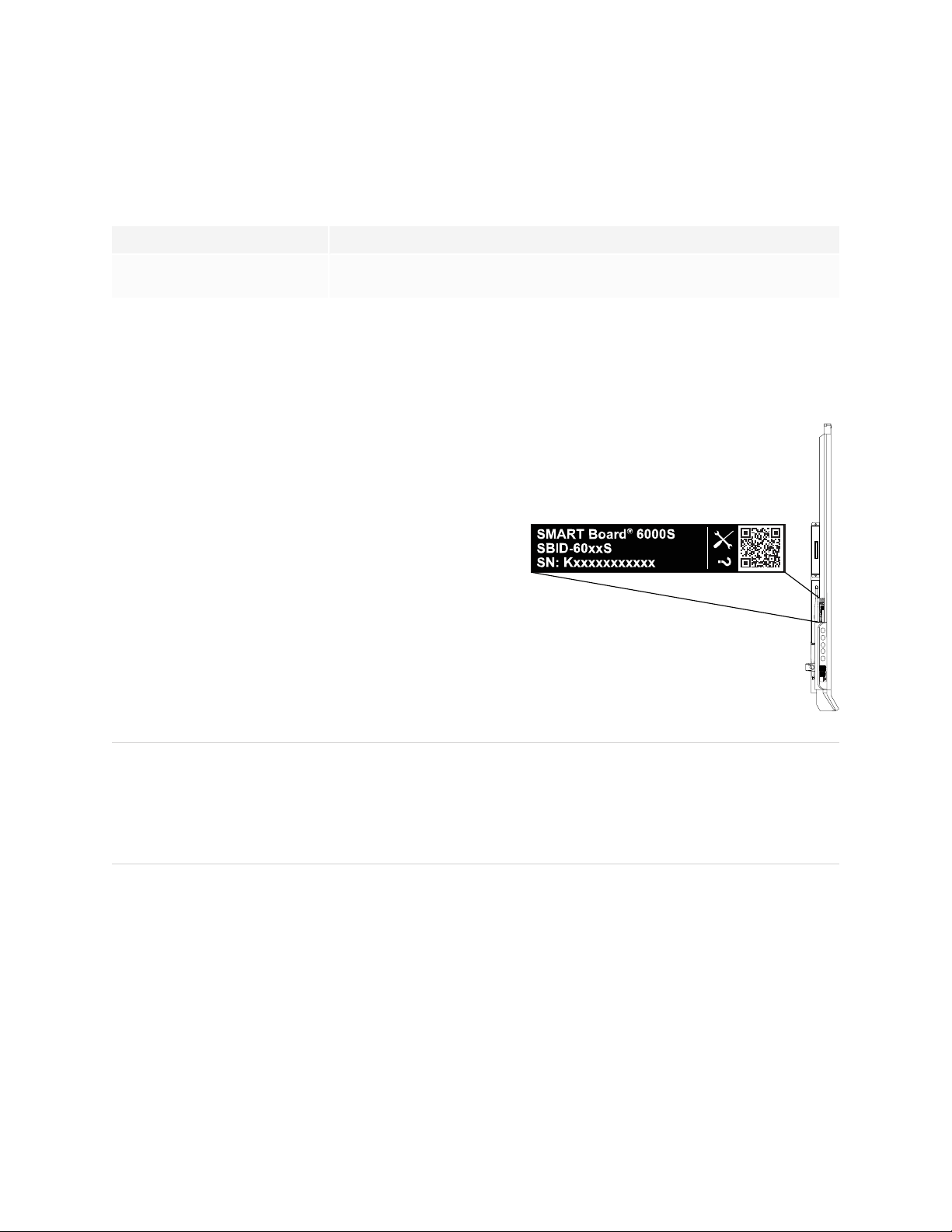
Chapter 5
Troubleshooting
The SMART OPS PC module isn’t working as expected
Symptom Troubleshooting steps
The SMART OPS PC module isn’t
working as expected.
See the SMART OPS PC modules user guide (smarttech.com/kb/171747).
Contacting your reseller for additional support
If an issue you’re experiencing with the display persists or isn’t covered in this chapter or the knowledge
base, contact your authorized SMART reseller (smarttech.com/where) for support.
Your reseller might ask you for the serial number for the
display. The serial number is on a label located on the left
side of the display (pictured).
TIPS
l Scan the QR code on the label to view the SMARTBoard 6000S or 6000S Pro series interactive
display support pages on the SMART website.
l You can also find the serial number in the iQ settings (see Serial Number on page65).
smar ttech.com/kb/171414 53
Page 54
Appendix A
Network settings 54
Personalization 55
Application settings 56
System settings 59
You can access settings using the icon on the Home screen.
NOTES
l Settings can apply to a user or to the entire system. User-level settings change depending on the
user who is signed in. System-level settings apply to all users. See the settings for more information.
l Some settings aren’t available while you’re signed in to your SMART Account. Sign out of your
SMART Account on the display to see all settings.
Network settings
Option Values Function Notes User or system
setting
Wi-Fi
Wi-Fi
[Wi-Finetwork name]
Wi-Fi MACaddress
Wi-Fi IPaddress
smar ttech.com/kb/171414 54
On
Off
[N/A] Shows information about the
[N/A] Shows MACaddress for the network
[N/A] Shows I Paddress for the network the
Enables or disables Wi-Fi on the
display.
connected wireless network.
the display is connected to.
display is connected to.
Turn on Wi-Fi to
discover
networks.
[N/A] System
[N/A] System
[N/A] System
System
Page 55
AppendixA
Adjusting settings
Option Values Function Notes User or system
setting
SMARTiQ Ethernet
Advanced options
StaticIP (Use DHCP)
Proxy (Use proxy)
Proxy (Auto-configure)
MAC Address
IP Address
Bluetooth
Bluetooth
View a vailable bluetooth
devices
[N/A] Options available when an Ethernet
cable is connected
On
Off
On
Off
On
Off
[N/A] Shows information about the network
[N/A] Shows information about the network
On
Off
[N/A] Shows available Bluetooth devices. Turn on Bluetooth
Enables or disables DHCP to assign
the display an IP address.
Enables or disables a proxy server for
connecting to the network.
Enables or disables automatic
configuration of the proxy server for
connecting to the network.
the display is connected to.
the display is connected to.
Enable or disable the display’s
Bluetooth.
[N/A] System
[N/A] User
[N/A] User
[N/A] User
[N/A] System
[N/A] System
Turn on Bluetooth
to view available
Bluetooth
devices.
to view available
Bluetooth
devices.
System
System
SMARTCloud
SMART Cloud Status
Service Region
[Status] Shows the status of SMART Cloud. [N/A] System
[N/A] Shows the ser vice region. [N/A] System
Personalization
NOTE
If iQ is disabled, Personalization settings are not available.
smar ttech.com/kb/171414 55
Page 56
AppendixA
Adjusting settings
Option Values Function Notes User or system
setting
Wallpaper
[Wallpapers] Select the wallpaper that
appears in the
background.
l 1920 × 1080 images
work best
l The display supports
.png and .jpg file
formats
l See Changing the
display’s wallpaper.
User
Application settings
NOTE
If iQ is disabled, Application settings are not available.
Option Values Function Notes User or system
setting
Launcher
SMARTNotebookPlayer
On
Off
Enables or disables SMART
Notebook Player in the Apps
Librar y.
[N/A] User
Browser
Screen Share
Files Library
Whiteboard Storage
Default Whiteboard
Location
Files Storage
Allow Google Drive
integration in Files
Librar y
On
Off
On
Off
[N/A] [N/A] [N/A] User
My Files > SLS
Files
My Files > Boar d
Files
[N/A] [N/A] [N/A] User
On
Off
Enables or disables Browser in the
Apps Library.
Enables or disables Screen Share
in the Apps Library.
Sets where new whiteboard files
are saved.
Enables or disables access to
Google Drive when you’re signed in
to your SMARTAccount.
[N/A] User
[N/A] User
See Syncing
SMARTNotebookand
SMARTLearning Suite
Online files to the iQ
experience.
See Opening your
Google Drive or
OneDrive on the
display.
User
User
smar ttech.com/kb/171414 56
Page 57

AppendixA
Adjusting settings
Option Values Function Notes User or system
setting
Allow OneDrive
integration in Files
Librar y
SMARTWhiteboard
Whiteboard Storage
Librar y
Save Whiteboards in
Librar y
Mobile App
Saving Whiteboards
Sharing Whiteboards
On
Off
Enables or disables access to
OneDrive when you’re signed in to
your SMARTAccount.
See Opening your
Google Drive or
OneDrive on the
User
display.
[N/A] [N/A] [N/A] User
On
Off
For 1 week
For 1 Month
Enables or disables saving kapp
Whiteboard sessions.
Sets how long kapp Whiteboard
sessions a re sa ved.
[N/A] User
[N/A] User
Indefinitely
On
Off
Enables or disables the Capture
function in the SMARTkapp app.
If this option is off, the
QR code is not visible.
User
The SMARTkapp app
cannot connect to the
display and your mobile
device cannot save
snapshots of the
display in the a pp.
On
Off
Enables or disables the I nvite
function on the SMARTkapp app.
If this option is off, you
cannot invite people to
User
your session.
Annotation
Enable annotation layers
Screen Share
Require Permission
AirPlay
Google Cast
On
Off
On
Off
On
Off
On
Off
Enables or disables annotations on
the Home screen, video input,and
most apps.
Enables or disables automatic
connection from a device sharing
its screen.
Enables or disables the AirPlay
protocol.
Enables or disables the Google
Cast protocol.
[N/A] User
[N/A] System
AirPlay is enabled by
System
default.
Google Cast is enabled
System
by default.
smar ttech.com/kb/171414 57
Page 58

AppendixA
Adjusting settings
Option Values Function Notes User or system
setting
Miracast
Performance Logging
Auto-disconnect from
Wififor Miracast
On
Off
On
Off
On
Off
Enables or disables the Miracast
protocol.
SMART Support may ask users to
enable Performance Logging to
help diagnose issues.
When enabled,the display
disconnects from the network
when a device shares its screen
using M iracast.
Miracast is enabled by
default.
IMPORTANT
Devices that use
AirPlay and Google
Cast can’t connect to
the display while a
Miracast device is
connected.
Performance Logging
is disabled by default.
SMARTrecommends
enabling this setting for
area s with high
network saturation or
busy networks.
IMPORTANT
Only one device can
connect to the
display when
Miracast is enabled.
This setting used to be
named “Miracast
Connection Handling”
System
System
System
Reset Screen Shar e
Use Web Player
[N/A] Closes and restarts the Screen
Share app and its discovery
services.
On
Off
When enabled,the display uses a
different method to str eam videos.
You can restart Screen
Share as a
troubleshooting step if
a mobile device or
computer can’t find or
connect to the display.
If this method doesn’t
work, disable it to
return to the original
method.
System
System
smar ttech.com/kb/171414 58
Page 59

AppendixA
Adjusting settings
System settings
Option Values Function Notes User or system
setting
System
Access to USB mass
storage devices
SMARTBoard with iQ
Default input
Home Button
Brightness
Home Button Activation
Interval
Power
Turn on when people
are nearby
On
Off
On
Off
Inputs availableon the display. Selectthe default input the
High
Medium
Low
80 milliseconds
180 milliseconds
280 milliseconds
560 milliseconds
1120 milliseconds
2080 milliseconds
On
Off
Enables or disables access to
a USB drive.
Enables or disables the iQ
experience.
display willuse when starting.
Sets the brightness of the
Home button LED.
Sets the sensitivityof the
Home button.
Sets the display to turn on if
the presence detection
sensors detects users in the
room.
[N/A] System
[N/A] System
The iQ
embedded
experience is the
default input.
Default is Low. System
Default is 80
milliseconds.
This option is off
by default.
System
System
System
Turn screen off after
smar ttech.com/kb/171414 59
Disabled
1 min
5 mins
30 mins
1 hour
1.5 hour s
2 hours
5 hours
10 hours
Sets the number of minutes of
inactivitybefore the display
goes to sleep.
The default is 60
minutes.
System
Page 60

AppendixA
Adjusting settings
Option Values Function Notes User or system
setting
Go to energy saving
mode after
Standby (Shutdown)
Networked Standby
(Sleep)
Display
Screen Adjustment
Brightness
Advanced Display Options
Color
Temperature
Disabled
1 min
5 mins
Sets the number of minutes of
inactivitybefore the display
enters energy saving mode .
30 mins
1 hour
1.5 hour s
2 hours
5 hours
10 hours
[N/A] If selected,the display wakes
up slowly.
[N/A] If selected,the display wakes
up faster
0–100 Sets the overa ll brightness of
the image.
Very Cool
Cool
Sets how colors appear on the
display.
Neutral
Warm
Very Warm
The default is 60
System
minutes.
This option is
System
more ener gy
efficient.
This option is less
System
energy efficient.
[N/A] System
[N/A] System
Lightness
0–488 Sets the overall lightness of
[N/A] System
the image.
Contrast
0–488 Sets the overall contra st of the
[N/A] System
image.
Saturation
0–511 Sets the overall satur ation of
[N/A] System
the image.
Red
0–448 Sets the overall r ed of the
[N/A] System
image..
Green
0–448 Sets the overall green of the
[N/A] System
image.
Blue
0–448 Sets the overall blue of the
[N/A] System
image.
HDMI Output
smar ttech.com/kb/171414 60
Page 61

AppendixA
Adjusting settings
Option Values Function Notes User or system
setting
Default resolution
HDMI I nput
Advanced
HDMISettings
Audio
Speakers
Built-in Speakers
Auto
4K60
1080p60
720p60
640x480p60
HDMI 2.0
HDMI 1.4b
Auto-detect
On
Off
Sets the HDMI out resolution. [N/A] System
Sets .the HDMI version for
each HDMIinput.
You can also
enable or disable
System
strictly
conformant
HDMIInput
DDCSDAtiming
and forbid or
allow HDCP2.2
with older
receivers.
Enables or disables the
display’s internal speakers.
When analog
speakers are
System
connected to the
display, the
display’s internal
speakers are
disabled
automatically.
Audio Properties
Balance
Bass
Treble
0–100 Sets the audio output from the
speakers.
Drag the slider all
the way to the left
System
to have all a udio
from the left
speaker. Drag the
slider all the way
to the r ight to
have all the audio
from the right
speaker.
0–100 Sets the bass level. [N/A] System
0–100 Sets the treble level. [N/A] System
smar ttech.com/kb/171414 61
Page 62

AppendixA
Adjusting settings
Option Values Function Notes User or system
setting
Date & Time
Automatic Date & Time
Date
Time
24 H our Time
Time Zone
Language
Country
On
Off
Sets the display’s date and
time automatically.
Configure the
network to allow
System
Network Time
Protocol(NTP)
requests to
internet time
servers. See
Connectingto a
network.
[N/A] Sets the display’s date. Disable
System
Automatic date
& time to set the
date manually.
[N/A] Sets the display’s time. Disable
System
Automatic date
& time to set the
time manua lly.
On
Off
Shows the display’s time using
the 24-hour clock.
[N/A] User
[N/A] Sets the display’s time zone. [N/A] System
[Languages] Sets the language for the
[N/A] User
settings menu.
[Countries] Sets the display’s country. [N/A] System
Diagnostics
Factory Reset
Save Log File to a USB
key
Submit Log fileto
SMART
Impr ove the Experience
Support ID
Logging Service
Enable Logging Service
[N/A] Resets all options to their
default values.
[N/A] Copy diagnostic logs to a USB
drive.
[N/A] Send diagnostic logs to
SMART.
On
Off
Sends usage statistics and
error reports to SMART.
[Support ID] Shows the support ID
associated with the display.
[Languages] Sets the language for the
settings menu.
On
Off
Enables or disables saving
logs to a USB drive
Only
[N/A]
administrators
should r eset the
display.
[N/A] [N/A]
[N/A] [N/A]
[N/A] User
[N/A] [N/A]
[N/A] User
[N/A] System
smar ttech.com/kb/171414 62
Page 63
AppendixA
Adjusting settings
Option Values Function Notes User or system
setting
Log Levels
Log Level RAW
Log Level SPM
Log Level RATP
Log Level SEP
Log Level EXT
Security
LockDown Settings
Make passwords visible
[N/A] [N/A] [N/A] [N/A]
On
Off
Advanced logging options to
be set under the direction of
[N/A] System
SMART Support
On
Off
Advanced logging options to
be set under the direction of
[N/A] System
SMART Support
On
Off
Advanced logging options to
be set under the direction of
[N/A] System
SMART Support
On
Off
Advanced logging options to
be set under the direction of
[N/A] System
SMART Support
On
Off
Advanced logging options to
be set under the direction of
[N/A] System
SMART Support
[N/A] Lockdown the display’s
settings using a certificate on
a USB drive.
See Locking
down the Settings
app for more
System
information.
On
Off
Reveals characters when
typinga password in an app
[N/A] System
or website
Install certificates
View certificates
Automatic inactivitylog
out
Clean up
Clean Up Policy
Clean Up the
whiteboard
[N/A] Install certificates to connect
[N/A] System
to a network.
[N/A] View installed certificates. [N/A] System
Enabled
Disabled
Disabled
Manually reset with the Clean
Automaticallylogs a user off
after a time of inactivity.
Sets how often the display
cleans up.
[N/A] System
[N/A] User
Up button in the launcher
1 hour
2 hours
3 hours
1 day
[N/A] Saves the Whiteboard session
[N/A] User
to the Library and erases the
Whiteboard.
smar ttech.com/kb/171414 63
Page 64

AppendixA
Adjusting settings
Option Values Function Notes User or system
setting
Clean Up the browser
Clean Up other
applications
Software Update
Updates Channel
Checkfor Updates Now
[N/A] Closes the browser tabs and
[N/A] User
clears the history, cache, and
cookies.
[N/A] Closes open applications. [N/A] User
Stable Channel
Beta Channel
Sets which iQ system software
updates the display receives.
When switching
from the Beta
System
channel to the
Stable channel, a
factory reset
occurs. See
page62 for more
information about
factory reset.
For more
information about
the Beta Channel,
see Switching to
the Beta channel.
[N/A] Checksfor updates to the
system software.
If an update is
available,the text
[N/A]
changes to Apply
NOTE
update now.
The display must be
connected to the internet to
checkfor system software
updates or a USB drive with
the system software
update file is connected to
the display.
Remote Management
Launch Remote
Mana gement Settings
[N/A] Configure the display’s
connection settings with the
RadixViso server.
This option is only
enabled when
Remote
System
Mana gement is
enabled.
Remote Management
Enabled
RadixViso version
On
Off
[N/A] Shows the RadixViso version. [N/A] System
Enables or disables Remote
Mana gement on the display.
[N/A] User
About
Help
[N/A] Shows the SMART support
[N/A] [N/A]
site.
Board Nam e
[N/A] Select a name for your display. [N/A] System
smar ttech.com/kb/171414 64
Page 65

AppendixA
Adjusting settings
Option Values Function Notes User or system
setting
Send Feedback
Board Details
Build Number
Serial N umber
Part Number
Model N umber
Configuration
Firmware Details
Touch controller version
Scaler version
Pen firmwar e version
[N/A] Send feature r equest to
[N/A] [N/A]
SMART.
[N/A] [N/A] [N/A] [N/A]
[N/A] Shows the iQ system
[N/A] [N/A]
software’s version number.
[N/A] Shows the display’s serial
[N/A] [N/A]
number.
[N/A] Shows the display’s part
[N/A] [N/A]
number.
[N/A] Shows the display’s model
[N/A] [N/A]
number.
[N/A] Shows the display’s iQ system
[N/A] [N/A]
configuration.
[N/A] [N/A] [N/A] [N/A]
[N/A] Shows the display’s touch
[N/A] [N/A]
controller version.
[N/A] Shows the display’s scaler
[N/A] [N/A]
version.
[N/A] Shows the display’s pen
[N/A] [N/A]
firmware version.
Legal Information
End User License
Agreement
Open Source Licenses
SMARTIntellectual
Property
[N/A] [N/A] [N/A] [N/A]
[N/A] Shows the SMART end user
[N/A] [N/A]
license agreement.
[N/A] Shows the open source
[N/A] [N/A]
licenses.
[N/A] Shows the SMART intellectual
[N/A] [N/A]
property information.
smar ttech.com/kb/171414 65
Page 66

Appendix B
Management
Your SMARTBoard 6000S or 6000S Pro has a built-in feature that enables you to enroll the display with
your organization’s SMART Remote Management account. When you enroll one of these displays, you can
use SMART Remote Management to centrally control features and settings for the display, such as:
l blocklists and allowlists
l Wi-Fi
l wallpaper
l certificates
l lock screen
l available apps
To learn how to enroll your display, see Enrolling a SMART Board interactive display in SMART Remote
Management.
smar ttech.com/kb/171414 66
Page 67
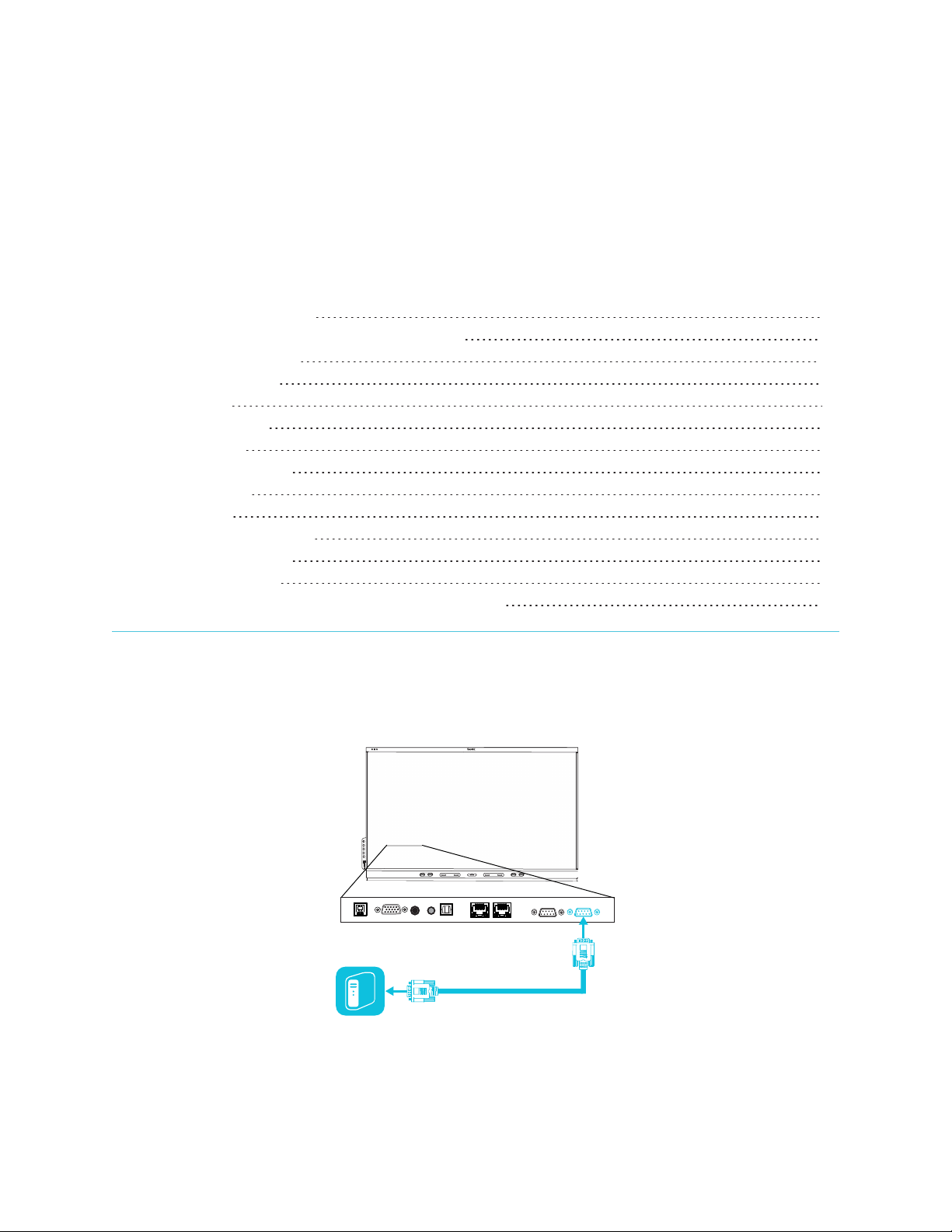
Appendix C
Connecting multiple displays 68
Configuring the computer’s serial interface settings 69
Commands and responses 69
Power state commands 72
Input commands 73
Brightness commands 74
Freeze commands 74
Screen shade commands 74
Volume commands 74
Mute commands 75
Firmware version commands 75
Serial number commands 75
Part number commands 76
Resolving issues with managing the display using RS-232 76
You can connect an RS-232 cable from a computer’s serial output to the display’s RS-232in connector to
remotely select video inputs, turn the display on or off, and get information about the display’s current
settings, such as volume and power state.
smar ttech.com/kb/171414 67
Page 68
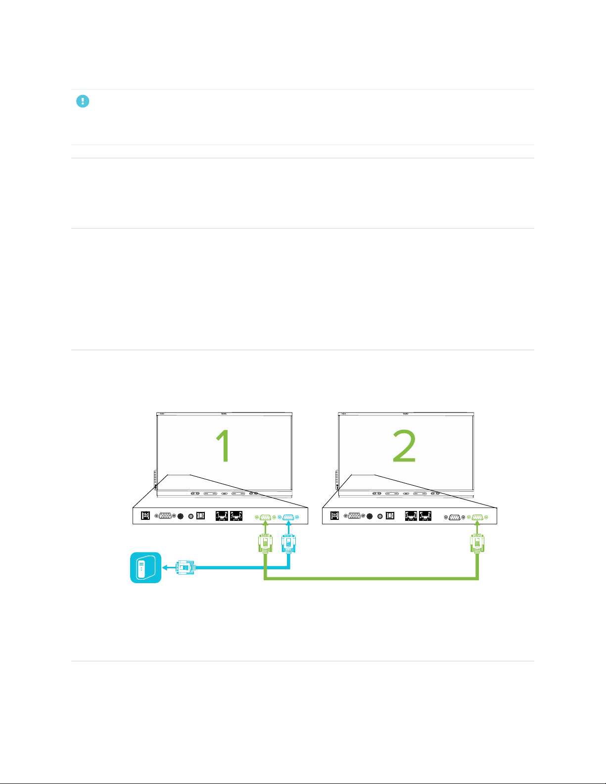
AppendixC
Managing the display using RS-232
IMPORTANT
Use only a standard RS-232 cable. Do not use a null modem cable. Null modem cables typically have
ends of the same type.
TIP
SMART also offers SMART RemoteManagement cloud-based device-management software, which you
can use to manage SMARTBoard interactive displays with iQ and devices running Windows, Chrome™
OS, Android™, and iOS operating systems. For more information, see SMART RemoteManagement.
Connecting multiple displays
You can connect up to ten displays to a room control system by connecting a RS-232 cable from the
computer’s serial output to the first display’s RS-232in connector and then connecting another RS-232
cable from that display’s RS-232out connector to the next display’s RS-232in connector.
NOTES
l The leftmost display (when viewed from the front) is the first display in the chain, the display to the
right of that display is the second display in the chain, and so on.
l When you connect displays in this manner, they behave as a single unit (see Mounting multiple
displays on page25).
l With the exception of the getinput, setinput, and getfwver, all remote management
commands apply to all connected displays.
smar ttech.com/kb/171414 68
Page 69

AppendixC
Managing the display using RS-232
Configuring the computer’s serial interface settings
Configure the computer’s serial interface before sending commands to the display.
To configure the computer’s serial interface
1. Turn on the display.
2. Turn on the computer, and then start the serial communications program or terminal emulation
program.
3. Activate local echo.
4. Configure the serial interface settings using the following values, and then press ENTER.
Baud rate 19200
Data length 8
Parity bit None
Stop bit 1
A command prompt (>) appears on the following line, and the display can now accept commands from
the computer.
NOTE
If no message appears or an error message appears, the serial interface isn’t configured correctly.
Repeat steps 3 and 4.
Commands and responses
To access display information or to adjust display settings using the room control system, type commands
after the command prompt (>) and wait for the response from the display.
CORRECT
>get volume
volume=55
>
In the example below, the user used =-50 instead of -50.
INCORRECT
>set volume=-50
smar ttech.com/kb/171414 69
Page 70

AppendixC
Managing the display using RS-232
invalid cmd: setvolume=-50
>
NOTES
l Use ASCII formatted commands.
l Commands aren’t case-sensitive and extra spacing is ignored.
l In many terminal applications on a computer, you can use the BACKSPACEkey when typing
commands.
l Review each entry carefully before sending a command to the display.
l Don’t send another command until you receive the response and the next command prompt (>). If no
command prompt is present, send a carriage return character (<CR>) to the display. If the display is
ready to receive commands, it will show a command prompt after receiving the carriage return.
To retrieve a setting’s current value
Use a get command.
This example shows how to get the volume:
>get volume
volume=55
>
To assign a value to a setting
Use a set command.
This example sets the volume to 65:
>set volume=65
volume=65
>
smar ttech.com/kb/171414 70
Page 71

AppendixC
Managing the display using RS-232
To increase or decrease the value of a setting
Use the set command to increase or decrease the value by a designated number.
This example increases the volume by 5:
>set volume+5
volume=70
>
This example decreases the volume by 15:
>set volume-15
volume=55
>
To identify or assign a value for a specific display
Start the command with [Display],@, where [Display] is the display you want to apply the
command to.
This example sets the input for the first display in the chain to HDMI 2:
>A,@ set input=hdmi2
@,A input=hdmi2
>
NOTES
o
The first display in the chain is labeled A, the next display is labeled B, and so on.
o
You can identify a specific display for only the getinput, setinput and getfwversion
commands.
smar ttech.com/kb/171414 71
Page 72

AppendixC
Managing the display using RS-232
Power state commands
Get command Set command Response
get powerstate set powerstate[Value]
Where [Value] is one of the following:
l
=on
l
=ready
l
=standby
l
=powersave
NOTE
powerstate=[Value]
Where [Value] is one of the following:
l
on
l
ready
l
standby
l
powersave
l
updateon
l
updateready
If the display is in UPDATEON or
UPDATEREADY state, it might not
change power states after receiving the
command.
The display has six power states:
Power state Description
ON The display is in normal operating mode.
READY The screen is off, but the display is ready to turn on when one of the following
occurs:
A user presses the Power button on the convenience panel or the remote
l
control.
A user picks up a pen or the eraser.
l
You send the setpowerstate=on command.
l
STANDBY The screen is off, and the display is in a low power state. The display enters READY
or ON state when one of the following occurs:
The proximity sensors detect people in the room.
l
A user presses the Power button on the convenience panel or the remote
l
control.
You send the setpowerstate=ready or setpowerstate=on command.
l
POWERSAVE The screen is off, and the display is a very low power state. The display enters
READY or ON state when one of the following occurs:
A user presses the Power button on the convenience panel or the remote
l
control.
You send the setpowerstate=powersave command.
l
smar ttech.com/kb/171414 72
Page 73

AppendixC
Managing the display using RS-232
Power state Description
UPDATEON The display is updating firmware. Do not turn off the display.
UPDATEREADY The display is updating firmware while the screen is off. Do not turn off the display.
With the exception of getpowerstate and setpowerstate, commands are available only when the
display is in READY or ON power state.
Input commands
Get command Set command Response
If one display is connected
get input set input[Value]
Where [Value] is one of the following:
l
=hdmi1
l
=hdmi2
l
=hdmi3
l
=vga1
l
=ops1
l
=android
If multiple displays are connected
[Display],@ get input
Where [Display] is the display’s label (A,
B, and so on).
[Display],@ set input[Value]
Where
l [Display] is the display’s label (A, B,
and so on).
l [Value] is one of the following:
o
=hdmi1
o
=hdmi2
o
=hdmi3
o
=vga1
o
=ops1
o
=android
input=[Value]
Where [Value] is one of the following:
l
hdmi1
l
hdmi2
l
hdmi3
l
vga1
l
ops1
l
android
l
none
@,[Display]input=[Value]
Where
l [Display] is the display’s label (A, B,
and so on).
l [Value] is one of the following:
o
hdmi1
o
hdmi2
o
hdmi3
o
vga1
o
ops1
o
android
o
none
smar ttech.com/kb/171414 73
Page 74

AppendixC
Managing the display using RS-232
Brightness commands
Get command Set command Response
get brightness set brightness[Value]
Where [Value] is one of the following:
l
+[Value]
l
-[Value]
l
=[5–100]
brightness=[Value]
Where [Value] is a number between 5
and 10 0
Freeze commands
Get command Set command Response
get videofreeze set videofreeze[Value]
Where [Value] is one of the following:
l
=on
l
=off
videofreeze=[Value]
Where [Value] is one of the following:
l
l
Screen shade commands
on
off
Get command Set command Response
get screenshade set screenshade[Value]
Where [Value] is one of the following:
l
=on
l
=off
screenshade=[Value]
Where [Value] is one of the following:
l
l
Volume commands
Get command Set command Response
get volume set volume[Value]
Where [Value] is one of the following:
l
+[Value]
l
-[Value]
l
=[0–100]
volume=[Value]
Where [Value] is a number between 0
and 10 0
on
off
smar ttech.com/kb/171414 74
Page 75

AppendixC
Managing the display using RS-232
Mute commands
Get command Set command Response
get mute set mute[Value]
Where [Value] is one of the following:
l
=on
l
=off
Firmware version commands
Get command Response
If one display is connected
get fwversion fwversion=[Value]
Where [Value] is the firmwar e version.
If multiple displays are connected
[Display],@ get fwversion
Where [Display] is the display’s label (A, B, and so on).
@,[Display]fwverversion=[Value]
Where
l [Display] is the display’s label (A, B, and so on).
l [Value] is the firmware version.
mute=[Value]
Where [Value] is one of the following:
l
on
l
off
Serial number commands
Get command Response
get serialnum serialnum=[Value]
Where [Value] is the serial number.
NOTE
If multiple displays a re connected, the response includes the
serial numbers for all displays separated by commas.
smar ttech.com/kb/171414 75
Page 76

AppendixC
Managing the display using RS-232
Part number commands
Get command Response
get partnum partnum=[Value]
Where [Value] is the part number, including the revision.
NOTE
If multiple displays a re connected, the response includes the
part num bers for all displays separated by commas.
Resolving issues with managing the display using
RS-232
The following table presents common issues with managing the display using RS-232 and explains how to
resolve them:
Symptom Troubleshooting steps
Mana ging the display using RS-232
isn’tworking as expected.
You’re experiencing other issues with
mana ging the display using RS-232,or
the previous steps don’t resolve the
issue.
l Make sure all the cable connections ar e secure.
l Restart the display and the remote management system.
See Tur ning off, turning on, and resetting the displayon page40.
l Configure the serial interface settings.
See Configuring the computer’s serial interface settings on page69.
See Chapter 5: Troubleshooting on page47.
smar ttech.com/kb/171414 76
Page 77

Appendix D
SMARTTechnologies supports global efforts to ensure that electronic equipment is manufactured, sold
and disposed of in a safe and environmentally friendly manner.
Waste Electrical and Electronic Equipment (WEEE)
Electrical and electronic equipment and batteries contain substances that can be harmful to the
environment and to human health. The crossed-out wheeled bin symbol indicates that products
should be disposed of in the appropriate recycling stream and not as regular waste.
Batteries
The product contains a CR2032 coin cell battery. The remote contains two AAA batteries. Recycle or
dispose of batteries properly.
Perchlorate material
The product coin cell battery contains perchlorate material. Special handling may apply. See
dtsc.ca.gov/hazardouswaste/perchlorate.
More information
See smarttech.com/compliance for more information.
smar ttech.com/kb/171414 77
Page 78

SMARTTECHNOLOGIES
smar ttech.com/support
smar ttech.com/contactsupport
smar ttech.com/kb/171414
 Loading...