

Page 1
Quick Start Guide
SR512nm
This Quick Start Guide shows you how to set up and start using your new gateway.
Page 2

INSTALLATION
1. Connect the DSL port of the gateway and the Modem port of the splitter with a telephone cable; connect the phone to the
phone port of the splitter through a cable; and connect the incoming phone line to the Line port of the splitter.
The splitter has three ports:
l Modem: Connect to the DSL interface of the gateway
l Phone: Connect to a telephone set
l Line: Connect to a wall phone jack (RJ11 jack)
2. Connect a LAN port of the gateway to the network card of the PC using an Ethernet cable.
3. Connect one end of the coaxial cable to the Coax port on the gateway and connect the other end of the cable to your setup
box.
4. Plug the power adapter into the wall outlet and connect the other end of it to the Power port of the gateway. Turn on the
unit by pressing the power button on the back of the gateway.
Note: If you use 3G WAN service, connect the 3G USB data card to the USB port of the gateway. If you use the Ethernet uplink,
connect the WAN port that is defined to the Internet with an Ethernet cable. The xDSL uplink, 3G WAN service, and Ethernet uplink
cannot coexist.
Your gateway is now automatically being set up to connect to the Internet. This process may take a few minutes to complete
before you can begin using your Internet applications (browser, email, etc.).
If you are unable to connect to the Internet, confirm that all connections are in place and the gateway’s power is turned on.
Page 3

DSL LAN WAN USBCOAX
DC/
IN
1
2
3
4
5
5 min
Page 4
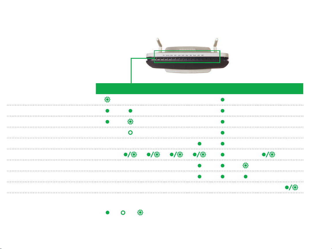
DSL 1-2 INTE RNET WAN LAN 1 -4 W IFI POW ER WPS USB 1- 2 COAX
DSL sync in progress
DSL sync acquired and gateway online
Gateway online and data transfer in progress
IP connection failure
WiFi enabled on modem
PC / network activity / data transfer
WPS Setup procedure in progress
WPS Connection completed successfully
MoCA® link up/ activity
: On : Off
: Blinking / Active
LED INDICATORS
The LEDs on the SR512nm can assist you
in better understanding the current state
of your gateway.
Page 5
QUICK GATEWAY CONFIGURATION
1
Warning: Do not press the Reset button unless you want to clear the current settings. The Reset button is in a small circular hole
on the rear panel. If you want to restore the default settings, insert a thin wire (such as a paper clip) into the hole, press the
Reset button gently for 1 second, and then release the button. The system reboots and returns to the factory defaults.
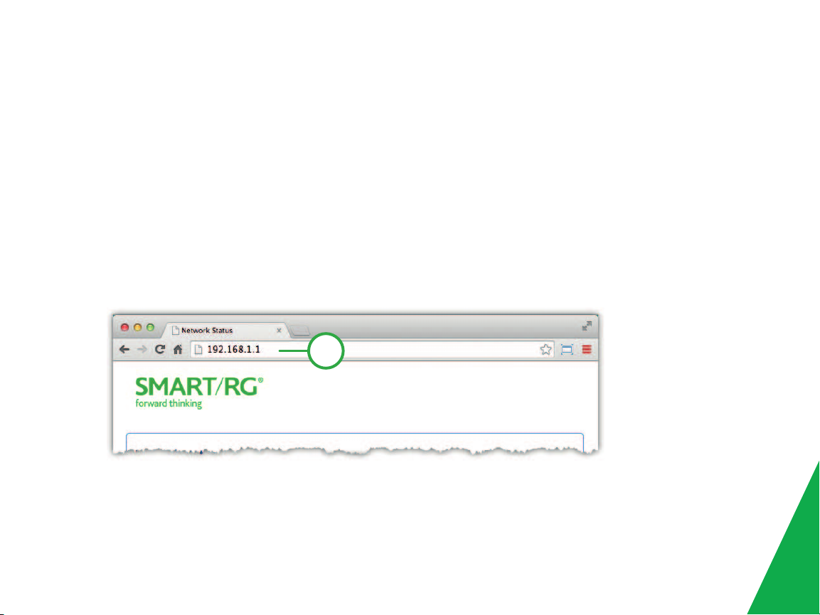
Logging in to your gateway
To change the settings on your gateway, you must log in to the gateway's interface. Make sure that you have completed the
steps in "INSTALLATION" before you begin.
1. Open your internet browser application and type 192.168.1.1 into the address line.
2. The login dialog appears. Enter the factory default credentials shown below and click Log In.
Page 6

User Name: admin Password: admin
Note: Your service provider may use other settings. Contact your provider for details.
Configuring the WAN manually
If the automatic connect process is unsuccessful, refer to the Advanced Setup > Layer 2 Interface and WAN Services sections of
the SmartRG SR2 3xx - SR5xx Gateway User Manual to manually establish a connection.
Page 7

WiFi Setup
Two methods, WPS and Manual, are available for WiFi setup. Perform the steps on this page for both methods, and then
follow the instructions for the applicable method.
1. In the top navigation bar, click WIFI and then click 2GHz or 5GHz in the left menu. The steps are the same for both
options. The wireless radio and SSID options are enabled by default.
2. In the Radio Configuration section, select options in the Regulatory Domain, Bandwidth Radio, and Channel fields.
3. In the SSID Configuration section, select options in the fields. Depending on the encryption method you select, you may
have to enter a passphrase in the Key field.
4. Continue with the steps for the method you prefer.
Page 8

WPS Method
If the device you wish to connect to the Internet via your gateway supports the WPS secure WiFi connection method, follow these
steps.
1. In the left navigation bar, click Wireless > Security.
2. Select Enable WPS and click Apply/Save to commit your selection.
3. On the left side of the gateway’s exterior, press the button labeled WPS.
.
4. Within 2 minutes, activate WPS on the 3rd party device to which you wish to connect. It may have a push button on its
exterior or a software interface is used to initiate the WPS connection. To learn how to use the WPS feature on your client
device, refer to its documentation.
Your device should now be connected to your router wirelessly using WPS. If you encounter problems with the WPS setup such as
connection failure, refer to your client device for further instructions.
Page 9

Manual Method
Set up your gateway’s parameters first, then follow these steps.
1. In the left navigation bar, select Wireless > Security and scroll down to the Manual Setup AP section.
2. If your gateway supports multiple wireless networks, select the SSID of the network you wish to configure. You will need
this ID for step 7.
3. Select the desired Network Authentication. Make sure that the host devices you intend to use support the selected
authentication type.
4. Choose a WPA Passphrase and type it in to this field. You will need this passphrase for step 7.
5. Select any desired encryption preferences in the lower three fields.
6. Click Apply / Save.
7. Follow the WiFi connection instructions provided with your client device to connect to the router. Use the SSID name you
selected in Step 2. Then enter the passphrase that you entered in step 4 in the appropriate location on the network setup
screen of your WiFi client device.
Page 10

FCC Statement
FCC - PART 68
This e quipment complies with Part 68 of the FCC rules and the requirements adopted by the ACTA. On the bottom case of this equipment is a label that contains, among other information, a
product identifier in the format US: VW7DL01BSR512NM.
This e quipment uses the following USOC jacks: RJ-11/RJ45/USB/Power Jacks.
A plug and ja ck used to connect this equipment to the pr emises wiring and telephone network must comply w ith the applicable FCC Par t 68 rules and requirements adopted by the ACTA. A
compliant telephone cord and modular plug is provided with this product. It is designed to be connected to a compatible modular jack that is also compliant. See installation instructions for details.
REN (RINGER EQUIVALENCY NUMBER) STATEMENT
Notice: The Ringer Equivalency Number (REN) assigned to each terminal device provides an indication of the maximumnumber of terminals allowed to be connected to a telephone interf ace. The
termination on an i nterf ace may consist of any combination of devices subject only to the requirement that the sum of the Ringer Equivalence Numbers of all the devices does not exceed 5.
If this equipment causes harm to the telephone network, the telephone company w ill notify you in advance that temporary discontinuance of ser vice may be required. But if advance notice isn't
practical, the telephone company will notify the customer a s soon as possible. Also, you will be advised of your right to file a complaint with the FCC if you believe it is necessary.
The telephone company may make changes in its facilitie s, equipment, operations or procedures that could affe ct the operation of the equipment. If this happens the telephone company w ill
provide adva nce notice in order for you to make necessary modifications to maintain uninterrupted service.
If trouble is exper ienced with this equipment, for repair or warranty inf ormation, please contact SmartRG,Inc. If the equipment is causing harm to the telephone network, the telephone company
may request that you disconnect the equipment until the problem is resolved.
Connection to party line service is subject to state tariffs. Contact the state public utility commission, public service commission or corporation commission for information.
If your home has specially wired alarm equipment connected to the te lephone line, ensure the installation of this device does not disable your ala rm equipment. If you have questions about what
will disable alarm equipment, consult your tele phone company or a qualif ied installer .
Page 11

IC CS-03 statement
This pr oduct meets the applicable Industry Canada technical specifications. / Le pré sent matériel est conforme aux specifications techniques applicables d’Industrie Canada.
The Ringer Equivalence Number (REN) is an indication of the maximumnumber of devices allowed to be connected to a te lephone interface. The termination of an interf ace may consist of any
combination of devices subject only to the requirement that the sum of the RENs of all the devices not exceed five. / L’indice d’é quivalence de la sonnerie (IES) sert à indiquer le nombre
maximal de terminaux qui peuvent êtr e raccordés à une i nterf ace téléphonique. La terminaison d’une interface peut consister en une combinaison quelconque de dispositifs, à la seule condition
que la somme d’indices d’é quivalence de la sonnerie de tous le s dispositifs n’excède pas cinq.
FCC Statement
This e quipment has been tested and found to comply with the limits for a Class B digital device, pursuant to part 15 of the FCC Rules. These limits ar e designed to provide reasonable protection
against harmful inter ference in a residential installation. This equipment generates, uses a nd can ra diate ra dio frequency energy and, if not installed and used in accordance w ith the
instructions, may cause harmful interf erence to radio communications. Howev er, there is no guarantee that interf erence w ill not occur in a particular installation. If this equipment does cause
harmful interf ere nce to radio or television reception, which can be dete rmined by turning the equipment of f and on, the user is encourage d to try to correct the interfe rence by one or more of
the following measures:
—Reorient or r elocate the receiving antenna.
—Increase the separation between the equipment and r eceiver .
—Connect the equipment into an outlet on a circuit different f rom that to which the re ceiver is connected.
—Consult the dealer or an experienced r adio/TV technician f or help.
FCC Radiation Exposure Statement
This device complies with FCC r adiation e xposure limits set forth for an uncontrolled environment and it also complies w ith Part 15 of the FCC RF Rules. This equipment must be installed and
operated in accordance with provided instructions and the antenna(s) used for this transmitter must be installed to provide a separa tion distance of at least 20 cm f rom all persons and must not
be co-located or operating in conjunction with any other antenna or tra nsmitter. End-users and installers must be pr ovided with antenna installation instructions and consider removing the no-
collocation statement.
Page 12

This device complies with Part 15 of the FCC Rules. Operation is subject to the following two conditions: (1) this device may not cause harmful inter ference, and (2) this device must a ccept any
interf ere nce r eceived, including inter ference that may cause undesired operation.
Caution!
Any changes or modifications not expressly approve d by the party responsible for compliance could void the user's authority to operate the equipment.
Canada Statement
This device complies with Industry Canada licence-exempt RSS standard(s). Operation is subject to the following two conditions: ( 1) this device may not cause interf erence, and (2) this device must
accept any interference, including interference that may cause undesired operation of the device.
Le pr ésent appareil est conforme aux CNR d'Industrie Canada applicables aux appar eils radio exempts de licence. L'exploitation est autorisée aux deux conditions suivantes : (1) l'a ppareil ne doit
pas produire de brouillage, et ( 2) l'utilisateur de l'appareil doit accepter tout brouillage radioélectrique subi, même si le brouillage est susceptible d'en compromettre le f onctionnement.
The device meets the e xemption from the routine evaluation limits in section 2.5 of RSS 102 and compliance with RSS-102 RF e xposure, users can obtain Canadian information on RF exposure and
compliance.
Le dispositif rencontre l'ex emption des limites courantes d'év aluation dans la section 2.5 de RSS 102 et la conformité à l'exposition de RSS-102 r f, utilisateurs peut obtenir l'i nformation canadienne
sur l'exposition et la conformité de rf.
This transmitter must not be co-located or oper ating in conjunction with any other antenna or transmitter. This equipment should be installed and oper ated with a minimum distance of 20
centimeters between the radiator and your body.
Cet émetteur ne doit pas être C o-placé ou ne fonctionnant en même temps qu' aucune a utre antenne ou émetteur. Cet équipement devr ait êtr e installé et actionné ave c une distance minimumde
20 centimètres entre le radiateur et votr e corps.
This r adio transmitter ( identif y the device by certif ication number, or model number if Category II) has been approved by Industry Canada to operate wi th the antenna types listed below with the
maximum permissible gain and required antenna impedance f or each antenna type indicated. Antenna types not included in this list, having a gain gre ater than the maximumg ain indicated for that
type, are strictly prohibited for use with this device.
Page 13

Le pr ésent émetteur radio (identif ier le dispositif par son numéro de certifi cation ou son numéro de modèle s' il fait partie du matérie l de catégorie I) a été a pprouvé par Industrie Canada pour
fonctionner avec les types d'antenne énumérés ci-dessous et ay ant un gain admissible maximal e t l'impédance requise pour chaque type d'antenne. Les types d'antenne non inclusdans cette
liste, ou dont le gain est supérieur au gain maximal indiqué, sont strictement interdits pour l'exploitation de l'émetteur.
Page 14

RECORD YOUR SR512nm WIFI SETTINGS
Predefined wireless settings If you change the preset wireless settings
WiFi network name (SSID)
Network key (password)
ADDITIONAL SUPPORT
If you require further instructions, please contact your local ISP Support.
SMARTRGINC. ALL RIGHTS RESERVED. COPYRIGHT2016 ©
 Loading...