


 Loading...
501 SE Columbia Shores Boulevard, Suite 500
Vancouver, Washington 98661 USA
+1 360 859 1780 / smartrg.com
/ Gateway User Manual
Model: SR506n
Release 1.0 |
December 2016 |

Table of Contents
Introduction |
4 |
Disclaimer |
4 |
Copyright and Trademarks |
4 |
Safety Warnings |
4 |
FCC Information |
5 |
Welcome! |
6 |
Purpose & Scope |
6 |
Intended Audience |
6 |
Getting Assistance |
6 |
Getting Familiar with your Gateway |
7 |
LED Status Indicators |
7 |
Connections |
8 |
Buttons |
9 |
On/Off Button |
9 |
Reset Button |
9 |
WPS Button |
9 |
WiFi Button |
9 |
Installing your SR506n Gateway |
10 |
Logging in to your Gateway's UI |
11 |
Device Info |
12 |
Summary |
12 |
WAN |
13 |
Statistics |
15 |
LAN |
15 |
WAN Service |
16 |
xTM |
16 |
xDSL |
17 |
References |
21 |
Route |
21 |
ARP |
23 |
DHCP |
24 |
Advanced Setup |
25 |
Layer2 Interface |
25 |
ATM Interface |
25 |
PTM Interface |
28 |
ETH Interface |
30 |
WAN Service |
31 |
PPP over Ethernet |
31 |
IP over Ethernet |
39 |
Bridging |
48 |
LAN |
51 |
IPv6 Autoconfig |
55 |
Ethernet Config |
56 |
NAT |
58 |
Virtual Servers |
58 |
Port Triggering |
60 |
DMZ Host |
62 |
Security |
62 |
IP Filtering - Outgoing |
63 |
IP Filtering - Incoming |
64 |
MAC Filtering |
66 |
Adding a MAC Filtering Rule |
67 |
Parental Control |
67 |
Time Restriction |
68 |
URL Filter |
69 |
Quality Of Service |
70 |
QoS Config |
70 |
Supported DSCP Values |
71 |
QoS Queue Config |
72 |
Wlan Queue |
74 |
QoS Classification |
74 |
QoS Port Shaping |
78 |
Routing |
80 |
Default Gateway |
80 |
Static Route |
80 |
Policy Routing |
81 |
RIP (Routing Information Protocol) |
82 |
DNS |
83 |
DNS Server |
84 |
Dynamic DNS |
85 |
Static DNS |
86 |
DSL |
87 |
UPnP |
89 |
DNS Proxy |
90 |
Storage Service |
90 |
Storage Device Info |
90 |
User Accounts |
91 |
Interface Grouping |
92 |
IP Tunnel |
94 |
IPv6inIPv4 |
94 |
IPv4inIPv6 |
95 |
IPSec |
95 |
Advanced IKE Settings |
98 |
Certificate |
99 |
Local |
99 |
Trusted CA |
101 |
Multicast |
102 |
Wireless |
106 |
Basic |
106 |
Security |
109 |
Open and Shared Network Authentication |
111 |
802.1X Network Authentication |
112 |
WPA2 and Mixed WPA2/WPA Network Authentic- |
|
ation |
114 |
WPA2-PSK and Mixed WPA2/WPA-PSK Network |
|
Authentication |
115 |
MAC Filter |
117 |
Wireless Bridge |
118 |
Advanced |
119 |
Station Info |
124 |
Diagnostics |
125 |
Diagnostics |
125 |
Ping Host |
126 |
Trace Route to Host |
127 |
Management |
127 |
Settings |
128 |
Backup |
128 |
Update |
128 |
Restore Default |
129 |
System Log |
130 |
Security Log |
131 |
SNMP Agent |
132 |
Management Server |
133 |
TR-069 |
134 |
STUN Config |
136 |
Internet Time |
137 |
SMARTRGINC. PROPRIETARY AND CONFIDENTIAL. ALL RIGHTS RESERVED. COPYRIGHT © 2016 |
2 |

Table of Contents
Access Control |
138 |
Accounts |
138 |
Add an Account |
138 |
Modify or Delete an Account |
140 |
Default Passwords |
141 |
Services |
141 |
Passwords |
143 |
Access List |
144 |
Logout Timer |
145 |
Update Software |
146 |
Reboot |
147 |
Logging Out |
148 |
Q&A |
149 |
Appendix A: Advanced Features |
150 |
Connect-and-Surf (Automatic Broadband Con- |
|
nection Configuration) |
150 |
Activation (Automatic ACS Connection Con- |
|
figuration) |
150 |
TR-069 Remote Management: Automated Con- |
|
figuration Server Support |
150 |
Appendix B: Gateway Feature Comparison |
152 |
Appendix C: FCC Statements |
154 |
FCC - Part 68 |
154 |
REN (RINGER EQUIVALENT NUMBERS) |
|
STATEMENT |
154 |
IC-CS03 statement |
154 |
FCC Statement |
155 |
FCC Radiation Exposure Statement |
155 |
Canada Statement |
155 |
5GHz |
156 |
Revision History |
157 |
SMARTRGINC. PROPRIETARY AND CONFIDENTIAL. ALL RIGHTS RESERVED. COPYRIGHT © 2016 |
3 |

Introduction
Disclaimer
SmartRG does not assume any liability arising out of the application or use of any products, or software described herein. Neither does it convey any license under its patent rights nor patent rights of others. SmartRG further reserves the right to make changes to any products described herein without notice. This publication is subject to change without notice.
Any trademarks mentioned in this publication are used for identification purposes only and may be properties of their respective owners.
Copyright and Trademarks
Copyright © 2016 by SmartRG, Inc.
The contents of this publication may not be reproduced in any part or as a whole, transcribed, stored in a retrieval system, translated into any language, or transmitted in any form or by any means, electronic, mechanical, magnetic, optical, chemical, photocopying, manual, or otherwise, without the prior written permission of SmartRG, Inc.
Published by SmartRG, Inc. All rights reserved.
Safety Warnings
For your safety, be sure to read and follow all warning notices and instructions.
•To reduce the risk of fire, use only No. 26 AWG (American Wire Gauge) or larger telecommunication line cord.
•Do NOT open the device or unit. Opening or removing covers can expose you to dangerous high voltage points or other risks. ONLY qualified service personnel can service the device. Contact your vendor for further information.
•Use ONLY the dedicated power supply for your device. Connect the power cord or power adapter to the correct supply voltage (110V AC in North America or 230V AC in Europe).
•Do NOT use the device if the power supply is damaged as it might cause electrocution.
•If the power supply is damaged, remove it from the power outlet.
•Do NOT attempt to repair the power supply. Contact your local vendor to order a new power supply.
•Place connecting cables carefully so that no one will step on them or stumble over them.
•Do NOT allow anything to rest on the power cord and do NOT locate the product where anyone can walk on the power cord.
•If you wall mount your device, make sure that no electrical, gas, or water pipes will be damaged.
•Do NOT install nor use your device during a thunderstorm. There may be a remote risk of electric shock from lightning.
•Do NOT expose your device to dampness, dust, or corrosive liquids.
•Do NOT use this product near water, for example, in a wet basement or near a swimming pool.
•Make sure to connect the cables to the correct ports.
SMARTRGINC. PROPRIETARY AND CONFIDENTIAL. ALL RIGHTS RESERVED. COPYRIGHT © 2016 |
4 |

•Do NOT obstruct the device ventilation slots, as insufficient airflow may harm your device.
•Do NOT store things on the device.
•Connect ONLY suitable accessories to the device.
FCC Information
See Appendix C: FCC_Statements.
SMARTRGINC. PROPRIETARY AND CONFIDENTIAL. ALL RIGHTS RESERVED. COPYRIGHT © 2016 |
5 |

Welcome!
Thank you for purchasing this SmartRG product.
SmartRG proudly brings you the best, most innovative broadband gateways available. SmartRG enables service providers to monitor, manage, and monetize the connected home through the design and production of reliable and highly interoperable hardware and software solutions.
As an early innovator in TR-069 remote management technology, SmartRG offers the finest in managed broadband and home networking solutions. Our products leverage various broadband access technologies and are outfitted with highly customizable software, meeting diverse service provider requirements. Based in the USA, SmartRG provides local, proactive software development and customer support. In the rapidly evolving broadband market, SmartRG helps service providers keep their businesses on the cutting edge through its laser-focused product line, leveraging the very latest in broadband access and home networking technologies. SmartRG solutions enable service providers to improve their bottom line by reducing service costs and increasing customer satisfaction.
Learn more at www.SmartRG.com.
Purpose & Scope
The purpose and scope of this document is to provide SmartRG customers with installation, configuration and monitoring information for the SR506n CPE.
Intended Audience
This document is intended for Network Architects, NOC Administrators, Field Service Technicians, and other networking professionals responsible for deploying and managing broadband access networks. Readers of this manual are assumed to have a basic understanding of desktop computer operating systems, networking concepts and telecommunications.
Getting Assistance
Subscribers: If you require help with this product, please contact your service provider.
Service providers: If you require help with this product, please open a support request.
SMARTRGINC. PROPRIETARY AND CONFIDENTIAL. ALL RIGHTS RESERVED. COPYRIGHT © 2016 |
6 |

Getting Familiar with your Gateway
This section contains descriptions of the SR506n gateway's lights, ports, and buttons.
LED Status Indicators
Your SmartRG gateway has several indicator lights (LEDs) on its exterior. The LED indicators are described below (from left to right).
INDICATOR |
ACTION DESCRIPTION |
|
|
|
|
Power |
|
Device is powered on and operating normally. |
|
|
Software is syncing. |
|
|
The device is powered off. |
DSL |
|
DSL link is established. |
|
|
The DSL line is training. |
|
|
The device is powered off. |
Internet |
|
Internet link is established. |
|
|
Data is being transmitted. |
|
|
Internet interface is disconnected. |
|
|
Authentication has failed. |
LAN 1-4 |
|
Ethernet interface is connected. |
|
|
Data is being transmitted. |
|
|
Ethernet interface is disconnected. |
USB |
|
3G or USB flash disk is connected. |
|
|
Data is being transmitted. |
|
|
No signal is detected. |
|
|
|
SMARTRGINC. PROPRIETARY AND CONFIDENTIAL. ALL RIGHTS RESERVED. COPYRIGHT © 2016 |
7 |
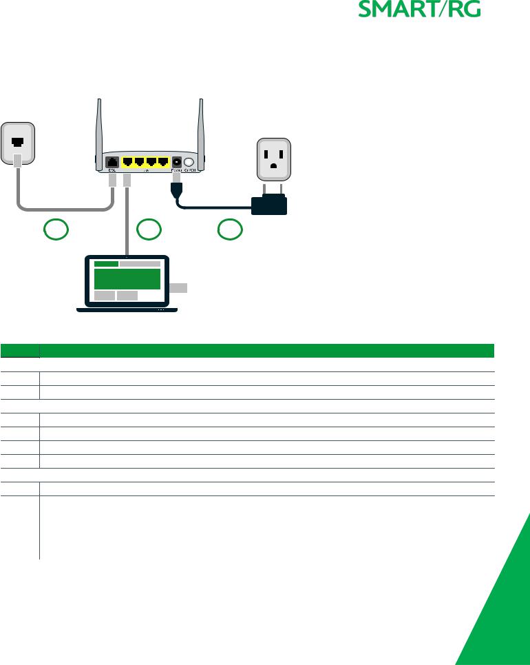
Connections
Below is an illustration of the connectors located on the back of the SR506n gateway.
1 |
2 |
3 |
The buttons and ports located on the gateway are described below.
Feature |
Description |
Top |
|
|
|
WiFi |
Button used for enabling or disabling the 5 GHz wireless function. |
WPS |
Button used for enabling or disabling the 2.4 GHz wireless function. |
Rearpanel |
|
DSL |
The grey RJ11 port is used to connect your gateway to an Internet provider via a DSL service. |
LAN 1 - 4 |
The yellow RJ45 ports can be used to connect client devices such as computers and printers to your gateway. |
Power |
Use only the power supply included with your gateway. Intended for indoor use only. |
On/Off |
Power switch. |
Left side |
|
USB |
Can transfer data, act as a printer interface, and handle a 3G accessory. |
Reset |
The Reset button is a small hole in the gateway's enclosure with the actual button mounted behind the surface. This |
|
style of push-button prevents the gateway from being inadvertently reset during handling. Reset must be actuated |
|
with a paper clip or similar implement. |
|
The Reset button is located on the left side of the unit. Press the button for at least 1 second and release. The factory |
|
default settings are restored. |
|
|
SMARTRGINC. PROPRIETARY AND CONFIDENTIAL. ALL RIGHTS RESERVED. COPYRIGHT © 2016 |
8 |

Buttons
On/Off Button
The On/Off button is located on the back of the gateway and turns the gateway on and off.
Reset Button
The Reset button is a small hole in the gateway's enclosure with the actual button mounted behind the surface. This style of pushbutton prevents the gateway from being inadvertently reset during handling. Reset must be actuated with a paper clip or similar implement.
The Reset button is located on the backleft side of the unit.
This pin-hole sized reset button has three functions. The duration for which the button is held dictates which function is carried out.
Hold Duration |
Effect |
Less than 6 |
Performs a modem reset that is equivalent to the Reboot function in the gateway software. |
seconds |
|
6-20 seconds |
Performs the software equivalent to the Restore Defaults function in the gateway software. |
20 or more seconds Changes the POWER LED to red and the gateway enters CFE mode which is a state associated with performing firmware updates via Internet browser.
WPS Button
The WPS button is located on the top of the unit. It triggers WPS (Wi-Fi Protected Setup™) mode. WPS is a standard means for creating a secure connection between your gateway and various wireless client devices. It is designed to simplify the pairing process between devices.
If you have client devices that support WPS, use this button to automatically configure wireless security for your network. For specific instructions, refer to the Quick Start Guide included with your gateway. Also see the Wireless section of this manual.
WiFi Button
The WiFi button is located on the top of the unit and toggles the WiFi radio on and off.
To activate the WiFi radio, press and hold the WiFi button for 3-5 seconds and then release. Repeat this step to deactivate the WiFi radio.
SMARTRGINC. PROPRIETARY AND CONFIDENTIAL. ALL RIGHTS RESERVED. COPYRIGHT © 2016 |
9 |

Installing your SR506n Gateway
1.Plug the power adapter into the wall outlet and then connect the other end to the Power port of the gateway.
2.Connect the LAN port of the gateway to the network card of the PC using an Ethernet cable.
3.Turn on the unit by pressing the On/Off button on the side of the gateway.
Note: If you use 3G WAN service, connect the 3G USB data card to a USB port of the gateway. If you use the Ethernet uplink, connect to the WAN interface using an Ethernet cable. You cannot use the xDSL uplink, 3G WAN service, and Ethernet uplink all at the same time.
Your gateway is now automatically being set up to connect to the Internet. This process may take a few minutes to complete before you can begin using your Internet applications (browser, email, etc.).
If you are unable to connect to the Internet, confirm that all cable connections are in place and the router’s power is turned on.
SMARTRGINC. PROPRIETARY AND CONFIDENTIAL. ALL RIGHTS RESERVED. COPYRIGHT © 2016 |
10 |
Logging in to your Gateway's UI
To manually configure the SmartRG SR555acSR655ac gateway, access the gateway's embedded UI.
1.Open a Web browser on your computer.
2.Enter http://192.168.1.1 (the default IP address of the DSL gateway) in the address bar. The login page appears where you can access the gateway's GUI or view the system log. For more information about configuring system logs, see the System Log topic in this User Manual.
3.Click the Manage gateway (advanced) link at the top right of the page.
4.Enter the admin user name and password. The default admin username/password are admin/admin. The default username/password of the common user are user/user. It is recommended that you change these default values after logging in to the DSL gateway for the first time.
5.Click OK. The gateway interface appears, showing the Device Info summary page.
SMARTRGINC. PROPRIETARY AND CONFIDENTIAL. ALL RIGHTS RESERVED. COPYRIGHT © 2016 |
11 |

Device Info
In this section, you can view information about your gateway's setup, status or nature of its connection with the provider and with LAN devices. You cannot interact with or change the settings in this section.
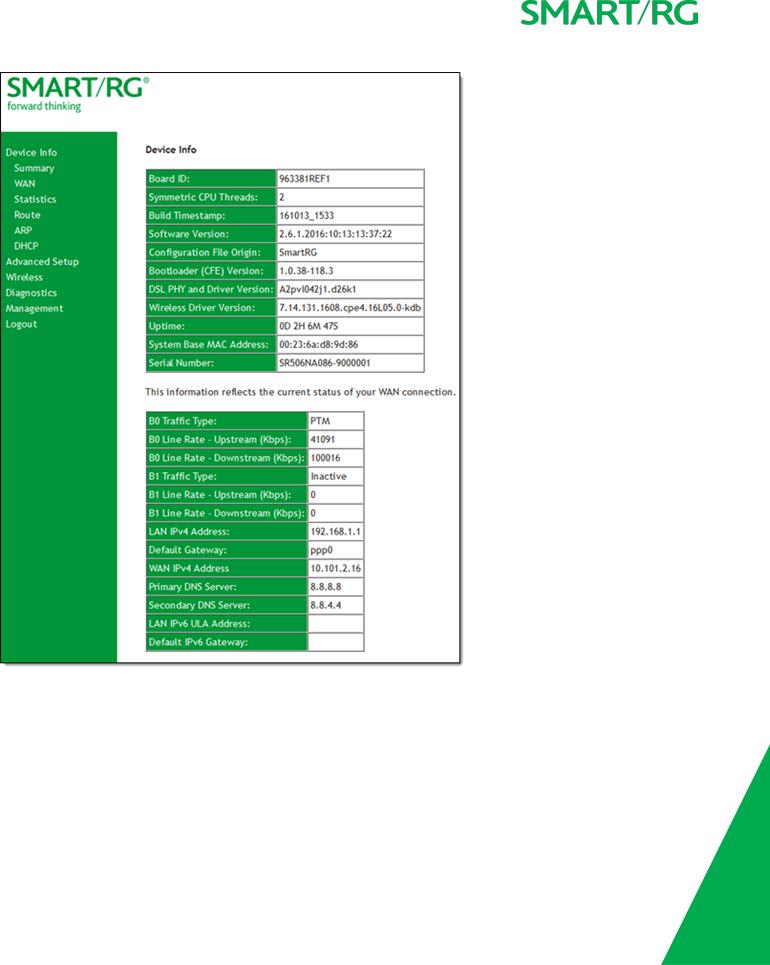
Summary
When you log into the gateway interface, the Device Info summary page appears. This page displays details about the hardware and software associated with your gateway. In addition, the current status of the WAN connection (if present) is shown.
SMARTRGINC. PROPRIETARY AND CONFIDENTIAL. ALL RIGHTS RESERVED. COPYRIGHT © 2016 |
12 |
WAN
On this page, you can view information about the connection between your ISP and your gateway. The WAN interface can be DSL or Ethernet and supports a number of Layer 2 and above configuration options (explained later in this document).
SMARTRGINC. PROPRIETARY AND CONFIDENTIAL. ALL RIGHTS RESERVED. COPYRIGHT © 2016 |
13 |

In the left navigation bar, click Device Info > WAN. The following page appears.
The fields on this page are explained in the following table.
Field Name |
Description |
|
|
Interface |
The connection interface (Layer 2 interface) through which the gateway handles the traffic. |
Description |
The service description such ipoe_0_0_1, showing the type of WAN and its ID. |
Type |
The service type. Options are PPPoE, IPoE, and Bridge. |
VlanMuxId |
The VLAN ID. Options are Disabled or 0-4094. |
IPv6 |
The state of IPv6. Options are Enabled and Disabled. |
Igmp Pxy |
The IGMP proxy. |
Igmp Src Enbl |
The IGMP source option is enabled for this connection. |
MLD Pxy |
The MLD proxy. |
MLD Src Enbl |
The MLD source option is enabled for this connection. |
NAT |
The state of NAT. Options are Enabled and Disabled. |
Firewall |
The state of the Firewall. Options are Enabled and Disabled. |
Status |
The status of the WAN connection. Options are Disconnected, Unconfigured, Connecting, and |
|
Connected. |
IPv4 Address |
The obtained IPv4 address. |
IPv6 Address |
The obtained IPv6 address. |
|
|
SMARTRGINC. PROPRIETARY AND CONFIDENTIAL. ALL RIGHTS RESERVED. COPYRIGHT © 2016 |
14 |

Statistics
In this section, you can view network interface information for LAN, WAN Service, xTM and xDSL. All data is updated in 15-minute intervals.
LAN
On this page, you can view the received and transmitted bytes, packets, errors and drops for each LAN interface configured on your gateway. Data is provided for the total bytes, packets, errors and drops as well as bytes and packets for multicast transmissions, and packets for unicast and broadcast transmission. All local LAN Ethernet ports, Ethernet WAN ports and w10 (Wireless Interface) are included.
In the left navigation bar, click Device Info > Statistics. The Statistics - LAN page appears where you can view detailed information about the status of your LAN.
To reset the counters, click Reset Statistics near the bottom of the page.
The fields on this page are explained in the following table.
Field Name |
Description |
|
|
|
|
Interface |
Available LAN interfaces. The only avalable option is LAN 1.Options are LAN1 - LAN4, WAN (if con- |
|
figured on your device), Wireless, and 2.4 Ghz and 5 Ghz. |
||
|
||
Received & Transmitted columns |
||
Bytes |
Number of packets in bytes. |
|
Pkts |
Number of packets. |
|
Errs |
Number of error packets. |
|
Drops |
Number of dropped packets. |
|
|
|
|
SMARTRGINC. PROPRIETARY AND CONFIDENTIAL. ALL RIGHTS RESERVED. COPYRIGHT © 2016 |
15 |
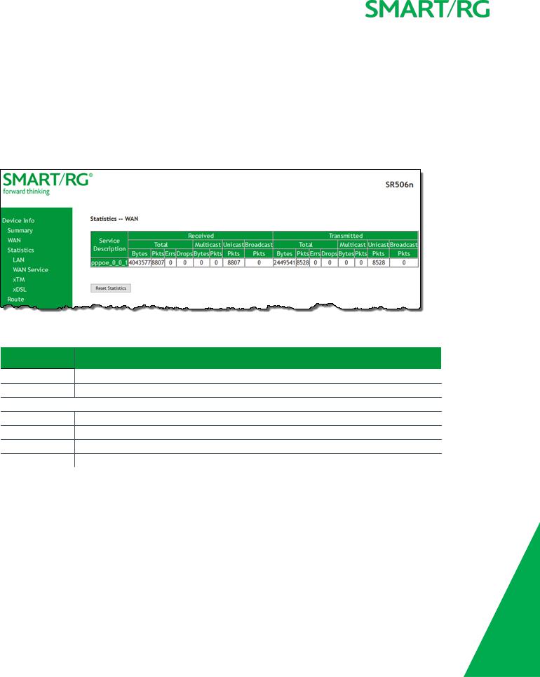
WAN Service
On this page, you can view the received and transmitted bytes, packets, errors and drops for each WAN interface for your SmartRG Gateway. Data is provided for the total bytes, packets, errors and drops as well as bytes and packets for multicast transmissions, and packets for unicast and broadcast transmission. All WAN interfaces configured for your gateway are included.
In the left navigation bar, click Device Info > Statistics > WAN Service. The Statistics - WAN page appears where you can view detailed information about the status of your WAN.
To reset the counters, click Reset Statistics near the bottom of the page.
The fields on this page are explained in the following table.
Field Name |
Description |
|
|
Interface |
Available WAN interfaces. Options are: atm, ptm, and eth. |
Description |
Service description. Options are: pppoe, ipoe, and bridge. |
Received & Transmitted columns |
|
Bytes |
Number of packets in bytes. |
Pkts |
Number of packets. |
Errs |
Number of error packets. |
Drops |
Number of dropped packets. |
|
|
xTM
On this page, you can view the ATM/PTM statistics for your gateway. All WAN interfaces configured for your SmartRG gateway are included.
In the left navigation bar, click Device Info > Statistics > xTM. The Interface Statistics page appears.
To reset these counters, click Reset near the bottom of the page.
SMARTRGINC. PROPRIETARY AND CONFIDENTIAL. ALL RIGHTS RESERVED. COPYRIGHT © 2016 |
16 |

The fields on this page are explained in the following table.
Field Name |
Description |
|
|
Port Number |
Statistics for Port 1, or both ports if Bonded. |
In Octets |
Total quantity of received octets. |
Out Octets |
Total quantity of transmitted octets. |
In Packets |
Total quantity of received packets. |
Out Packets |
Total quantity of transmitted packets. |
In OAM Cells |
Total quantity of received OAM cells. |
Out OAM Cells |
Total quantity of transmitted OAM cells. |
In ASM Cells |
Total quantity of received ASM cells. |
Out ASM Cells |
Total quantity of transmitted ASM cells. |
In Packet Errors |
Total quantity of received packet errors. |
In Cell Errors |
Total quantity of received cell errors. |
|
|
xDSL
On this page, you can view the DSL statistics for your gateway. All xDSL (VDSL or ADSL) interfaces configured for your SmartRG gateway are included. The terms and their explanations are derived from the relevant ITU-T standards and referenced accordingly.
SMARTRGINC. PROPRIETARY AND CONFIDENTIAL. ALL RIGHTS RESERVED. COPYRIGHT © 2016 |
17 |
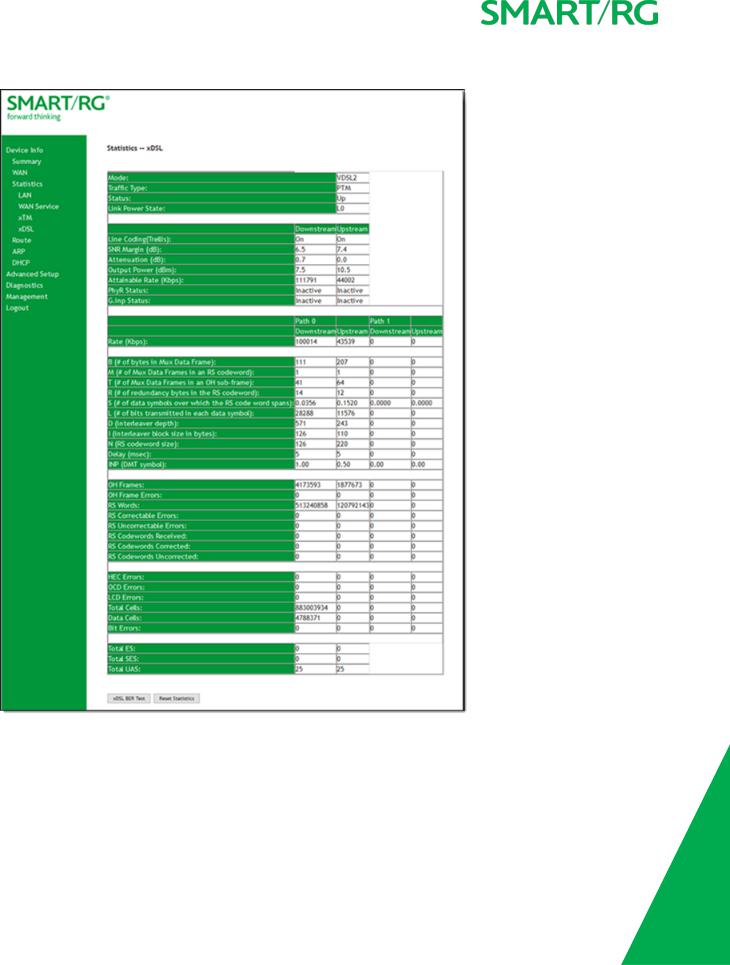
1. In the left navigation bar, click Device Info > Statistics > xDSL. The Statistics - xDSL page appears.
2.To run an xDSL Bit Error Rate (BER) test which determines the quality of the xDSL connection:
a.Scroll to the bottom of the page and click xDSL BER Test. The ADSL BER Test dialog box appears.
b.In the Tested Time field, select the duration in seconds and click Start. Options range from 1 second to 360 seconds. The default is 20 seconds.
The test transfers idle cells containing a known pattern and compares the received data with this known pattern.
SMARTRGINC. PROPRIETARY AND CONFIDENTIAL. ALL RIGHTS RESERVED. COPYRIGHT © 2016 |
18 |

Comparison errors are tabulated and displayed in the dialog box.
3. To reset the counters, click Reset Statistics at the bottom of the page.
The fields on this page are explained in the following table.
Field Name |
Description |
Mode |
xDSL mode that the modem has trained under, such as ADSL2+, G.DMT, etc. |
Traffic Type |
Connection type. Options are: ATM and PTM. |
Status |
Status of the connection. Options are: Up, Disabled, NoSignal, and Initializing. |
Link Power State |
Current link power management state (e.g., L0, L2, L3). |
Downstream and Upstream columns
Line Coding (Trellis) State of theTrellis Coded Modulation. Options are On and Off.
SNR Margin (dB) |
The signal-to-noise ration margin (SNRM) is the maximum increase (in dB) of the received |
|
noise power, such that the modem can still meet all of the target BERs over all the frame |
|
bearers. [2] |
Attenuation (dB)
Output Power (dBm)
The signal attenuation is defined as the difference in dB between the power received at the near-end and that transmitted from the far-end. [2]
Transmission power from the gateway to the DSL loop relative to one Milliwat (dBm).
Attainable Rate |
The typically obtainable sync rate, i.e., the attainable net data rate that the receive PMS-TC |
(Kbps) |
and PMD functions are designed to support under the following conditions: |
•Single frame bearer and single latency operation
•Signal-to-Noise Ratio Margin (SNRM) to be equal or above the SNR Target Margin
•BER not to exceed the highest BER configured for one (or more) latency paths
•Latency not to exceed the highest latency configured for one (or more) latency paths
•Accounting for all coding gains available (e.g., trellis coding, RS FEC) with latency bound
SMARTRGINC. PROPRIETARY AND CONFIDENTIAL. ALL RIGHTS RESERVED. COPYRIGHT © 2016 |
19 |

Field Name |
Description |
|
|
|
• Accounting for the loop characteristics at the instant of measurement [2] |
PhyR Status |
Physical Layer Retransmission feature status. Options are Inactive and Active. |
G.inp Status |
The status of video data retrieval from the buffer. Options are Inactive and Active. |
Rate (Kbps) |
The current net data rate of the xDSL link. Net data rate is defined as the sum of all frame |
|
bearer data rates over all latency paths. [2] |
Downstream and Upstream columns for DSL-specific fields only |
|
B (# of bytes in Mux |
The nominal number of bytes from frame bearer #n per Mux Data Frame at Reference Point A |
Data Frame) |
in the current latency path. |
M (# of Mux Data |
The number of Mux Data Frames per FEC Data Frame in the current latency path. |
Frames in FEC Data |
|
Frame |
|
T (Mux Data Frames |
The ratio of the number of Mux Data Frames to the number of sync bytes in the current |
over sync bytes) |
latency path. |
R (# of check bytes |
The number of Reed Solomon redundancy bytes per codeword in the current latency path. |
in FEC Data Frame) |
This is also the number of redundancy bytes per FEC Data Frame in the current latency path. |
S (ratio of FEC over |
The ratio of FEC over PMD Data Frame length. |
PMD Data Frame |
|
length) |
|
L (# of bits in PMD |
The number of bits from the latency path included per PMD. |
Data Frame) |
|
D (interleaver |
The interleaving depth in the current latency path, used to manager error correction. |
depth) |
|
I (interleaver block |
The block sizeused for interleaving data transmissions. |
size in bytes) |
|
N (RS codeword |
The size of the Reed-Solomon (RS) codeword used for managing error correction. |
size) |
|
Delay (msec) |
The PMS-TC delay in milliseconds of the current latency path (or the lowest latency path |
|
when running dual-latency paths). |
INP (DMT symbol) |
The input level for DMT-managed DSL environments. |
(End of DSL-specific field group) |
|
OH Frames |
The number of xDSL OH Frames transmitted/received. |
OH Frame Errors |
The number of xDSL OH Frames transmitted/received with errors. |
RS Words |
The number of Reed-Solomon-based Forward Error Correction (FEC) codewords trans- |
|
mitted/received. |
RS Correctable |
The number of Reed-Solomon-based FEC codewords received with errors that have been cor- |
Errors |
rected. |
RS Uncorrectable |
The number of Reed-Solomon-based FEC codewords received with errors that were not cor- |
Errors |
rectable. |
RS Codewords |
(Visible only for gateways connected via DSL) Total number of Reed-Solomon Codewords |
Received |
received. |
RS Codewords Cor- |
(Visible only for gateways connected via DSL) Total number of Reed-Solomon Codewords cor- |
rected |
rected. |
|
|
SMARTRGINC. PROPRIETARY AND CONFIDENTIAL. ALL RIGHTS RESERVED. COPYRIGHT © 2016 |
20 |
Field Name |
Description |
|
|
|
|
RS Codewords |
(Visible only for gateways connected via DSL) Total number of Reed-Solomon Codewords |
|
Uncorrected |
Uncorrected |
|
HEC Errors |
A count of ATM HEC errors detected. As per ITU-T G.992.1 and G.992.3, a1-byte HEC is gen- |
|
|
erated for each ATM cell header. Error detection is implemented as defined in ITU-T I.432.1 |
|
|
with the exception that any HEC error shall be considered as a multiple bit error, and there- |
|
|
fore, HEC Error Correction is not performed. [1],[2] |
|
OCD Errors |
Total number of Out-of-Cell Delineation errors. ATM Cell delineation is the process which |
|
|
allows identification of the cell boundaries. The HEC field is used to achieve cell delineation. |
|
|
[4] An OCD Error is counted when the cell delineation process transitions from the SYNC state |
|
|
to the HUNT state. [2] |
|
LCD Errors |
Total number of Loss of Cell Delineation errors. An LCD Error is counted when at least one |
|
|
OCD error is present in each of four consecutive overhead channel periods and SEF (Severely |
|
|
Errored Frame) defect is present. [2] |
|
Total Cells |
The total number of cells (OAM and Data cells) transmitted/received. |
|
Data Cells |
The total number of data cells transmitted/received. |
|
Bit Errors |
The total number of Idle Cell Bit Errors in the ATM Data Path. [3] |
|
Total ES |
Total number of Errored Seconds. This parameter is a count of 1-second intervals with one or |
|
|
more CRC-8 anomalies. [4] |
|
Total SES |
Total number of Severely Errored Seconds. An SES is declared if, during a 1-second interval, |
|
|
there are 18 or more CRC-8 anomalies in one or more of the received bearer channels, or one |
|
|
or more LOS (Loss of Signal) defects, or one or more SEF (Severely Errored Frame) defects, or |
|
|
one or more LPR (Loss of Power) defects. [4] |
|
Total UAS |
Total number of Unavailable Seconds. This parameter is a count of 1-second intervals for |
|
which the xDSL line is unavailable. The xDSL line becomes unavailable at the onset of 10 con- |
||
|
||
|
tiguous SESs. These 10 SES’s shall be included in the unavailable time. Once unavailable, the |
|
|
xDSL line becomes available at the onset of 10 contiguous seconds with no SESs. These 10 |
|
|
seconds with no SES’s shall be excluded from unavailable time. [4] |
References
[1]ITU-T Recommendation G.992.1 (1999), Asymmetric digital subscriber line (ADSL) transceivers.
[2]ITU-T Recommendation G.992.3 (2005), Asymmetric digital subscriber line transceivers 2 (ADSL2).
[3]ITU-T Recommendation G.997.1 (2006), Physical layer management for digital subscriber line (DSL) transceivers.
[4]ITU-T Recommendation I.432.1 (1999), B-ISDN user-network interface – Physical layer specification: General characteristics.
Route
On this page, you can view the LAN and WAN route table information configured in your SmartRG Gateway for both IPv4 and IPv6 implementation.
In the left navigation bar, click Device Info > Route. The following page appears.
SMARTRGINC. PROPRIETARY AND CONFIDENTIAL. ALL RIGHTS RESERVED. COPYRIGHT © 2016 |
21 |
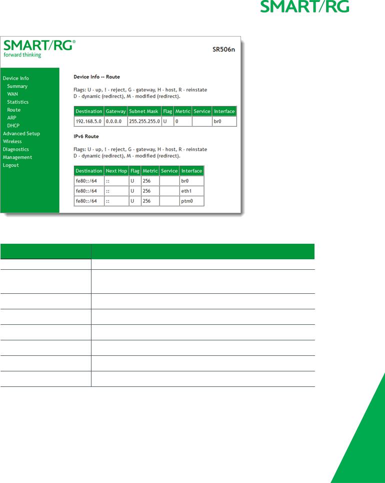
The fields on this page are explained in the following table.
Field Name |
Description |
IPv4 & IPv6 route fields |
|
|
|
Destination (Including IPv6 |
Destination IP addresses. |
Route) |
|
Gateway |
Gateway IP address. |
Subnet Mask |
Subnet mask for the gateway. |
Flag (Including IPv6 Route) |
Status of the flags. See detailed descriptions above the tables. |
Metric (Including IPv6 Route) |
Number of hops required to reach the default gateway. |
Service (Including IPv6 Route) |
Service type. |
Interface (Including IPv6 Route) |
WAN/LAN interface. |
IPv6 Route only fields |
|
|
|
SMARTRGINC. PROPRIETARY AND CONFIDENTIAL. ALL RIGHTS RESERVED. COPYRIGHT © 2016 |
22 |
Field Name |
Description |
|
|
Destination |
Destination IP addresses. |
Next Hop |
Next hop IP address. |
|
|
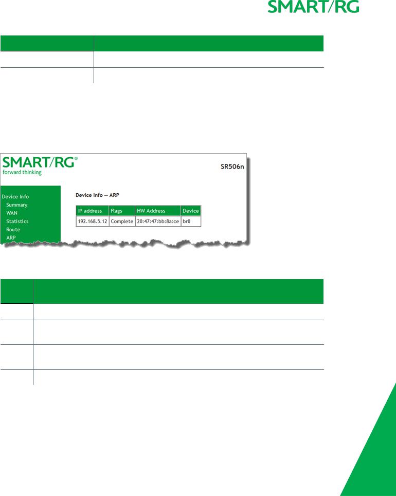
ARP
On this page, you can view the host IP addresses and their hardware (MAC) addresses for each LAN Client connected to the gateway via a LAN Ethernet port or wireless LAN.
In the left navigation bar, click Device Info > ARP. The following page appears.
The fields on this page are explained in the following table.
Field |
Description |
Name |
|
|
|
IP address |
The IP address of the host. |
Flags |
Each entry in the ARP cache is marked with one of these flags. Options are: Complete, Permanent, and |
|
Published. |
HW |
The hardware (MAC) address of the host. |
Address |
|
Device |
The system level interface by which the host is connected. Options are: br(n), atm(n), and ptm(n). |
|
|
SMARTRGINC. PROPRIETARY AND CONFIDENTIAL. ALL RIGHTS RESERVED. COPYRIGHT © 2016 |
23 |
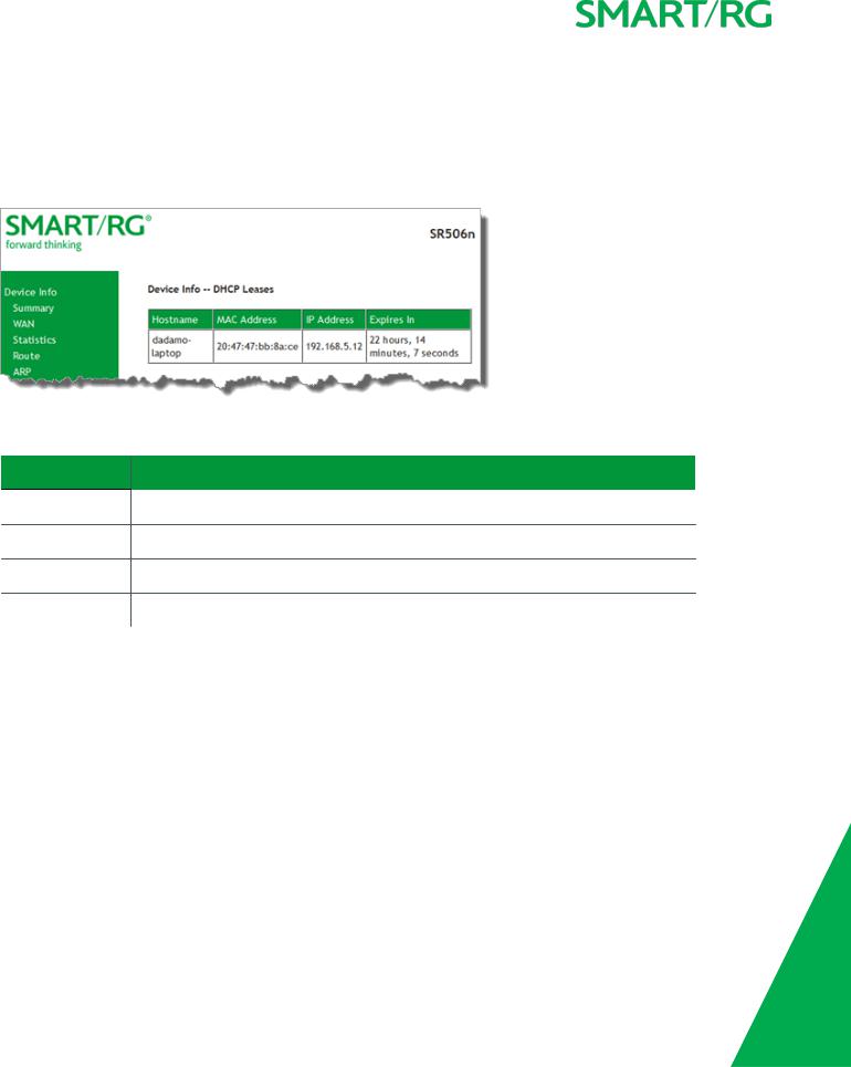
DHCP
The DHCP page displays a list of locally connected LAN hosts and their DHCP lease status, which are directly connected to the SmartRG Gateway via a LAN Ethernet port or Wireless LAN.
In the left navigation bar, select Device Info > DHCP. The following page appears.
The fields on this page are explained in the following table.
Field Name |
Description |
|
|
Hostname |
The host name of each connected LAN device. |
MAC Address |
The MAC Address for each connected LAN device. |
IP Address |
The IP Address for each connected LAN device. |
Expires In |
The time until the DHCP lease expires for each LAN device. |
|
|
SMARTRGINC. PROPRIETARY AND CONFIDENTIAL. ALL RIGHTS RESERVED. COPYRIGHT © 2016 |
24 |

Advanced Setup
In this section, you can configure network interfaces, security, quality of service settings, and many other settings for your gateway and network.
Layer2 Interface
In this section, you can configure interfaces for ATM and PTM interfaces. Generally you can accept the settings configured by default. If your network is highly customized, you may need to modify some of the settings, such as Username and Password.
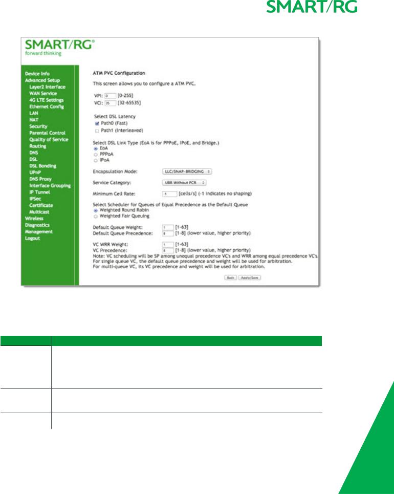
ATM Interface
On this page, you can configure Asynchronous Transfer Mode / Permanent Virtual Conduit (ATM/PVC) settings for your gateway. You can customize latency options, link type, encapsulation mode, and more.
Note: Devices (routers) on both ends of the connection must support ATM / PVC.
1.In the left navigation bar, click Advanced Setup > Layer2 Interface > ATM Interface and then click Add. The following page appears.
SMARTRGINC. PROPRIETARY AND CONFIDENTIAL. ALL RIGHTS RESERVED. COPYRIGHT © 2016 |
25 |
2.Modify the settings as desired, using the information provided in the table below.
3.Click Apply/Save to commit your changes.
The fields on this page are explained in the following table.
Field Name |
Description |
|
|
VPI |
Enter a Virtual Path Identifier. A VPI is an 8-bit identifier that uniquely identifies a network path |
|
for ATM cell packets to reach its destination. A unique VPI number is required for each ATM |
|
path. This setting works with the VCI. Each individual DSL circuit must have a unique VPI/VCI |
|
combination. String limits are: 0-255. |
VCI |
Enter a Virtual Channel Identifier. A VCI is a 16-bit identifier that has a unique channel. Options |
|
are: 32-65535. |
Select DSL |
Select the level of DSL latency. Options are: |
|
|
SMARTRGINC. PROPRIETARY AND CONFIDENTIAL. ALL RIGHTS RESERVED. COPYRIGHT © 2016 |
26 |

Field Name |
Description |
Latency |
• Path0 Fast: No error correction and can provide lower latency on error free lines. |
|
|
|
• Path1 Interleaved: Error checking that provides error free data which increases latency. |
|
• Path0 and Path1: If you are not certain which method is best, you can select both. |
Select Link Type Select the linking protocol. EoA is the most popular with PPPoA a close second (used with many legacy ISPs). Options are:
|
• EoA: Ethernet over ATM. |
|
|
• |
PPPoA: Point-to-Point Protocol over ATM. |
|
• |
IPoA: Internet Protocol over ATM. |
Encapsulation |
Select whether multiple protocols or only one protocol is carried per PVC (Permanent Virtual |
|
Mode |
Circuit). Options are: |
|
•LLC/ENCAPSULATION: (Available for PPOA only) Logical Link Control (LLC) encapsulation protocols used with multiple PVCs
•LLC/SNAP-BRIDGING: LLC used to carry multiple protocols in a single PVC.
•LLC/SNAP-ROUTING: (Available for IPoA only) LLC used to carry one protocol per PVC.
•VC/MUX: Virtual Circuit Multiplexer creates a virtual connection used to carry one protocol per PVC.
Service Category Select the bit rate protocol. Options are:
•UBR without PCR: Unspecified Bit Rate with no Peak Cell Rate, flow control or time synchronization between the traffic source and destination. Commonly used with applications that can tolerate data / packet loss.
•UBR with PCR: Same as above but with a Peak Cell Rate.
•CBR: Constant Bit Rate relies on timing synchronization to make the network traffic predictable. Used commonly in Video and Audio traffic network applications.
•Non Realtime VBR: Non Realtime Variable Bit Rate used for connections that transport traffic at a Variable Rate. This category requires a guaranteed bandwidth and latency. It does not rely on timing synchronization between the destination and source.
•Realtime VBR: Realtime Variable Bit Rate. Same as the above option but relies on timing and synchronization between the destination and source. This category is commonly used in networks with compressed video traffic.
SMARTRGINC. PROPRIETARY AND CONFIDENTIAL. ALL RIGHTS RESERVED. COPYRIGHT © 2016 |
27 |

Field Name |
Description |
|
|
|
|
Minimum Cell |
Minimum allowable rate (cells per second) at which cells can be sent on a ATM network. The |
|
Rate |
default is -1 (no shaping). |
|
Scheduler for |
The algorithm used to schedule the queue behavior. VC scheduling is different than the default |
|
Queues of Equal |
queues. Options are: |
|
Precedence as |
• Weighted Round Robin: Packets are accessed in a round robin style. Classes can be |
|
the Default |
||
assigned. |
||
Queue |
||
• Weighted Fair Queuing: Packets are assigned to a specific queue. |
||
|
||
|
• Default Queue Weight: The default weight of the specified queue. Options are 1-63. |
|
|
• Default Queue Precedence: The precedence of the specified group. Options are 1-8. |
|
|
• VC WRR Weight: The weight of the specified virtual channel queue. Options are 1-63. |
|
|
• VC Precedence: The priority of the specified virtual channel queue. Options are 1-8. |
|
|
|
PTM Interface
The SmartRG gateway's VDSL2 standards support Packet Transfer Mode (PTM). An alternative to ATM mode, PTM transports packets (IP, PPP, Ethernet, MPLS, and others) over DSL links. For more information, refer to the IEEE802.3ah standard for Ethernet in the First Mile (EFM). Some 500 series gateways have a PTM interface configured by default.
On this page, you can configure a PTM interface for your gateway.
1.In the left navigation bar, click Advanced Setup > Layer2 Interface > PTM Interface and then click Add. The following page appears.
SMARTRGINC. PROPRIETARY AND CONFIDENTIAL. ALL RIGHTS RESERVED. COPYRIGHT © 2016 |
28 |

2.Modify the settings as desired.
3.Click Apply/Save to commit your changes.
The fields on this page are explained in the following table.
Field Name |
Description |
|
|
Weighted Round Robin |
Time slices are assigned to each process in equal portions and in circular order, hand- |
|
ling all processes without priority (also known as cyclic executive). |
Weighted Fair Queuing |
A data packet scheduling technique allowing different scheduling priorities to be |
|
assigned to statistically multiplexed data flows. Since each data flow has its own |
|
queue, an ill-behaved flow (that sent larger packets or more packets per second than |
|
the others since it became active) will only affect itself and not other sessions. |
Default Queue Weight |
Enter a default weight of the specified queue. Options are: 1-63. |
Default Queue Pre- |
Enter a precedence for the specified queue. Options are: 1-8. |
cedence |
|
Default Queue Minimum |
The default minimum rate at which traffic can pass through the queue. For no shaping, |
Rate |
enter -1 (disabled). Options are: 1-0 Kbps. |
Default Queue Shaping |
The shaping rate for the specified queue. Options are: 1-0 Kbps. The default is -1 (no |
|
|
SMARTRGINC. PROPRIETARY AND CONFIDENTIAL. ALL RIGHTS RESERVED. COPYRIGHT © 2016 |
29 |

Field Name |
Description |
|
|
Rate |
shaping). |
Default Queue Shaping |
The maximum rate at which traffic can pass through the queue. Options are 1600 or |
Burst Rate |
greater. |
|
|
ETH Interface
On this page, you can configure an Ethernet interface for your gateway.
Note: If a WAN port is already configured, you must remove it before you can define a new one. The Add button does not appear until the existing port is removed. Modify or delete any WAN service that uses it. Then, return to this page and click the Remove checkbox and then click the Remove button.
1.In the left navigation bar, click Advanced Setup > Layer2 Interface > ETH Interface. If no WAN port is configured, the following page appears.
2.Click Add.
3.If a WAN port is already configured or you clicked Add, the following page appears.
4.Select the LAN port you wish to act as a WAN port.
5.Click Apply/Save to commit your changes.
SMARTRGINC. PROPRIETARY AND CONFIDENTIAL. ALL RIGHTS RESERVED. COPYRIGHT © 2016 |
30 |
Loading...