

Page 1

GATEWAY USER MANUAL
For all Broadcom chipset-based models including:
ADSL 3xx series: SR300n, SR350n, SR360n
VDSL 5xx series: SR500n, SR505n, SR510n, SR550n, SR552n
Release 3.0
June, 2014
Page 2

TABLE OF CONTENTS
Introduction
Welcome! ........................................................................ 6
Thank you for purchasing this SmartRG product. ............ 6
Purpose & Scope ........................................................................ 6
Intended Audience ......................................................... 6
Getting Assistance ......................................................... 6
Getting Familiar With Your Gateway .......................................... 6
LED Status Indicators: ......................................................... 7
Connections: ........................................................................ 8
External Buttons: ........................................................................ 9
Logging in to Your SmartRG Gateway’s UI ......................... 11
Device Info
Summary ...................................................................... 13
Wan Info ...................................................................... 13
Wan Info ...................................................................... 14
Statistics ...................................................................... 14
LAN ..................................................................................... 15
WAN Service ......................................................................16
xTM ..................................................................................... 17
xDSL ..................................................................................... 18
Route ..................................................................................... 22
ARP ..................................................................................... 23
DHCP ..................................................................................... 24
Advanced Setup
Layer2 Interface ...................................................................... 25
ATM Interface ......................................................................25
PTM Interface ...................................................................... 27
ETH Interface ...................................................................... 29
WAN Service ......................................................................29
PPP over Ethernet ....................................................... 29
IP Over Ethernet ...................................................................... 35
NAT
Virtual Servers (Port Forward) ........................................ 40
Port Triggering ...................................................................... 41
DMZ Host ...................................................................... 43
Security
IP Filtering ...................................................................... 44
Incoming ...................................................................... 45
MAC Filtering ...................................................................... 46
Parental Control ...................................................................... 48
URL Filter ...................................................................... 49
Quality of Service ...................................................................... 50
QoS Cong ...................................................................... 50
QoS Classication ....................................................... 54
QoS Port Shaping ...................................................................... 56
Routing ..................................................................................... 57
Default Gateway ...................................................................... 57
Static Route ...................................................................... 58
Policy Routing ...................................................................... 59
RIP (Routing Information Protocol) ........................................ 60
DNS ..................................................................................... 61
Dynamic DNS ...................................................................... 62
Static DNS ...................................................................... 63
DSL ..................................................................................... 64
DSL Bonding ...................................................................... 67
UPnP ..................................................................................... 68
DNS Proxy ...................................................................... 69
Interface Grouping ....................................................... 70
IP Tunnel ......................................................................72
IPv6inIPv4 ...................................................................... 72
IPv4inIPv6 ...................................................................... 73
IPSec ..................................................................................... 74
Certicate ...................................................................... 76
Local ..................................................................................... 76
Trusted CA ...................................................................... 78
Multicast ......................................................................79
501 SE Columbia Shores Boulevard, Suite 500, Vancouver, Washington 98661, USA l +1 360 859 1780
SmartRG Inc. Propriety and Condential. All Rights Reserved. Copyright © 2014 smartrg.com
Page 2
Page 3

Wireless
Basic ..................................................................................... 81
Security ..................................................................................... 83
Manual Setup ...................................................................... 85
Network Authentication: Open and Shared ......................... 85
Manual Setup ...................................................................... 86
Network Authentication: 802.1X ........................................ 86
Manual Setup ...................................................................... 87
Network Authentication: WPA ........................................ 87
Manual Setup ...................................................................... 88
Network Authentication: WPA-PSK ........................................ 88
Manual Setup ...................................................................... 89
Network Authentication: WPA2 ........................................ 89
Manual Setup ...................................................................... 90
Network Authentication: WPA2-PSK ........................................ 90
Manual Setup ...................................................................... 91
Network Authentication: Mixed WPA2-WPA ......................... 91
Manual Setup ...................................................................... 92
Network Authentication: Mixed WPA2/WPA-PSK .......... 92
MAC Filter ...................................................................... 93
Wireless Bridge ...................................................................... 94
Advanced ...................................................................... 95
Station Info ...................................................................... 99
STUN Cong .................................................................... 108
Internet Time .................................................................... 109
Access Control .................................................................... 110
Services ................................................................................... 110
Passwords .................................................................... 112
Update Software ....................................................................113
Reboot ................................................................................... 113
Appendix A: SmartRG™ Residential
Gateways
Connect-and-Surf (Automatic Broadband Connection Congu-
ration) ................................................................................... 114
Activation (Automatic ACS Connection Conguration)
.................................................................................................. 114
TR-069 Remote Management: Automated Conguration Server
Support ................................................................................... 114
Anegy ACS .................................................................... 115
Cisco Prime Home™ ACS ..................................................... 115
Calix Compass/Consumer Connect ACS ....................... 115
Appendix B: SmartRG Product Family –
Feature comparison matrix
Diagnostics
Diagnostics .................................................................... 100
Fault Management ..................................................... 101
Management
Settings ................................................................................... 102
Backup ................................................................................... 102
Update ................................................................................... 103
Restore Default .................................................................... 104
System Log .................................................................... 104
Security Log .................................................................... 105
Management Server ..................................................... 106
TR-069 Client .................................................................... 106
501 SE Columbia Shores Boulevard, Suite 500, Vancouver, Washington 98661, USA l +1 360 859 1780
SmartRG Inc. Propriety and Condential. All Rights Reserved. Copyright © 2014 smartrg.com
Page 3
Page 4

INTRODUCTION
Copyright ©2014 by SmartRG, Inc.
The contents of this publication may not be reproduced in any part or as a whole, transcribed, stored in a retrieval system, trans-
lated into any language, or transmitted in any form or by any means, electronic, mechanical, magnetic, optical, chemical, photo-
copying, manual, or otherwise, without the prior written permission of SmartRG, Inc.
Published by SmartRG, Inc. All rights reserved.
Disclaimer
SmartRG does not assume any liability arising out of the application or use of any products, or software described herein. Either
does it convey any license under its patent rights nor patent rights of others. SmartRG further reserves the right to make changes
to any products described herein without notice. This publication is subject to change without notice.
Trademarks
Any trademarks mentioned in this publication are used for identication purposes only and may be properties of their respective
owners.
Federal Communications Commission (FCC) Interference Statement
This device complies with Part 15 of the FCC Rules. Operation is subject to the following two conditions:
• This device may not cause harmful interference.
• This device must accept any interference received, including interference that may cause undesired operation.
This equipment has been tested and found to comply with the limits for a Class B digital device, pursuant to part 15 of the FCC
Rules. These limits are designed to provide reasonable protection against harmful interference in a residential installation. This
equipment generates, uses and can radiate radio frequency energy and, if not installed and used in accordance with the instruc-
tions, may cause harmful interference to radio communications. However, there is no guarantee that interference will not occur in
a particular installation.
If this equipment does cause harmful interference to radio or television reception, which can be determined by turning the equip-
ment off and on, the user is encouraged to try to correct the interference by one or more of the following measures:
• Reorient or relocate the receiving antenna.
• Increase the separation between the equipment and receiver.
• Connect the equipment into an outlet on a circuit different from that to which the receiver is connected.
• Consult the dealer or an experienced radio/TV technician for help.
This Class B digital apparatus complies with Canadian ICES-003
Cet appareil numérique de la classe B est conforme à la norme NMB-003 du Canada.
501 SE Columbia Shores Boulevard, Suite 500, Vancouver, Washington 98661, USA l +1 360 859 1780
SmartRG Inc. Propriety and Condential. All Rights Reserved. Copyright © 2014 smartrg.com
Page 4
Page 5

FCC Caution
Any changes or modications not expressly approved by the party responsible for compliance could void the user’s authority to
operate this equipment.
IMPORTANT NOTE: FCC Radiation Exposure Statement
This equipment complies with FCC radiation exposure limits set forth for an uncontrolled environment. This equipment should be
installed an operated with a minimum distance of 20cm between the radiator and your body.
This transmitter must not be co-located or operating in conjunction with any other antenna or transmitter.
SmartRG Inc declares that the WR100 is limited to operations on Channels 1 through 11, from 2400 to 2483.5 MHz by specied
rmware controlled in the USA.
Safety Warnings
For your safety, be sure to read and follow all warning notices and instructions.
• To reduce the risk of re, use only No. 26 AWG (American Wire Gauge) or larger telecommunication line cord.
• Do NOT open the device or unit. Opening or removing covers can expose you to dangerous high voltage points or other
risks. ONLY qualied service personnel can service the device. Please contact your vendor for further information.
• Use ONLY the dedicated power supply for your device. Connect the power cord or power adaptor to the correct supply
voltage (110V AC in North America or 230V AC in Europe).
• Do NOT use the device if the power supply is damaged as it might cause electrocution.
• If the power supply is damaged, remove it from the power outlet.
• Do NOT attempt to repair the power supply. Contact your local vendor to order a new power supply.
• Place connecting cables carefully so that no one will step on them or stumble over them. Do NOT allow anything to rest
on the power cord and do NOT locate the product where anyone can walk on the power cord.
• If you wall mount your device, make sure that no electrical, gas, or water pipes will be damaged.
• Do NOT install nor use your device during a thunderstorm. There may be a remote risk of electric shock from lightning.
• Do NOT expose your device to dampness, dust, or corrosive liquids.
• Do NOT use this product near water, for example, in a wet basement or near a swimming pool.
• Make sure to connect the cables to the correct ports.
• Do NOT obstruct the device ventilation slots, as insucient airow may harm your device.
• Do NOT store things on the device.
• Connect ONLY suitable accessories to the device.
501 SE Columbia Shores Boulevard, Suite 500, Vancouver, Washington 98661, USA l +1 360 859 1780
SmartRG Inc. Propriety and Condential. All Rights Reserved. Copyright © 2014 smartrg.com
Page 5
Page 6

Welcome!
Thank you for purchasing this SmartRG product.
SmartRG proudly brings you the best, most innovative broadband gateways available. SmartRG enables service providers to moni-
tor, manage, and monetize the connected home through the design and production of reliable and highly interoperable hardware
and software solutions.
As an early innovator in TR-069 remote management technology, SmartRG offers the nest in managed broadband and home
networking solutions. Our products leverage various broadband access technologies and are outtted with highly customizable
software, meeting diverse service provider requirements. Based in the USA, SmartRG provides local, proactive software develop-
ment and customer support. In the rapidly evolving broadband market, SmartRG helps service providers keep their businesses
on the cutting edge through its laser-focused product line, leveraging the very latest in broadband access and home networking
technologies. SmartRG solutions enable service providers to improve their bottom line by reducing service costs and increasing
customer satisfaction.
Learn more at www.SmartRG.com.
Purpose & Scope
The purpose and scope of this document is to provide the customers of SmartRG with installation, conguration and monitoring
information for all CPE platforms.
Intended Audience
The information in this document is intended for Network Architects, NOC Administrators, Field Service Technicians and other
networking professionals responsible for deploying and managing broadband access networks. The reader of this manual is as-
sumed to have a basic understanding of desktop computer operating systems, networking concepts and telecommunications.
Getting Assistance
Subscribers: If you require help with this product, please contact your service provider.
Service providers: if you require help with this product, please open a support request.
Getting Familiar With Your Gateway
This section contains a quick description of the Gateway’s lights, ports, and buttons. We produce several models that vary slightly
in there capabilities (See Appendix B for details) but the basic scheme of lights and ports and buttons exist on each model.
501 SE Columbia Shores Boulevard, Suite 500, Vancouver, Washington 98661, USA l +1 360 859 1780
SmartRG Inc. Propriety and Condential. All Rights Reserved. Copyright © 2014 smartrg.com
Page 6
Page 7
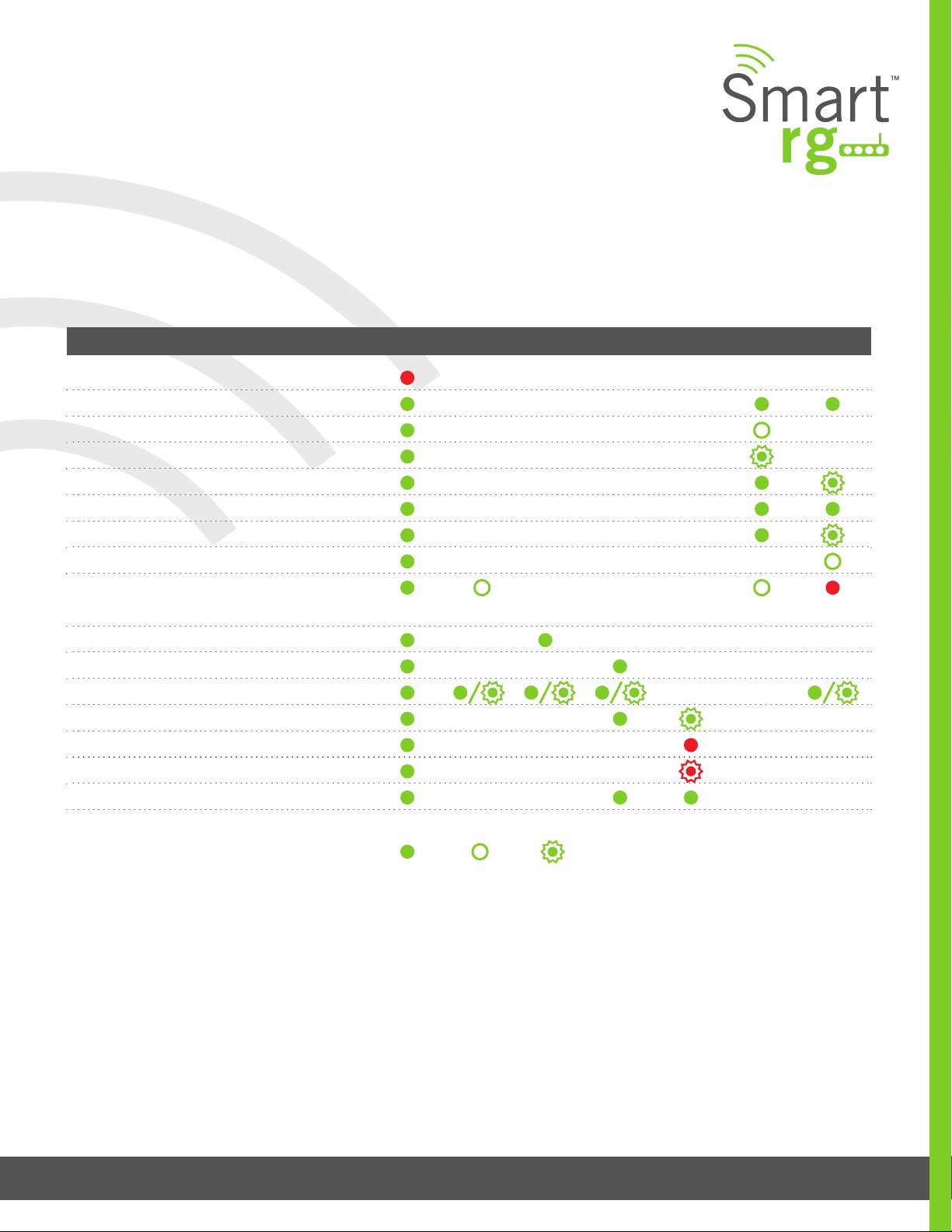
LED Status Indicators:
Your SmartRG gateway has several indicator lights (LEDs) on its front panel. The number of DSL ports or USB ports may vary from
model to model but generally, these indicators are available on all models:
POWER WAN LAN 1-4 WLAN WPS DSL 1 or 2 INTERNET
Power up test failure
DSL sync acqui red and gateway online
No sync to DSL line
DSL sync in progress
Mode m authenticatio n in progres s
DSL sync acqui red and gateway online
Gateway online and data transf er in progress
IP connec tion failure
Connec tion dropp ed – attemptin g
re-authent icat ion
LAN devic e on network connec ted
Wi-Fi enabled on modem
PC / net work activity / data transf er
WPS Setu p procedur e in progres s
Failur e to f ind any partne r with whic h to pai r
Sessio n overlap de tected. Possibl e securit y risk
WPS Connec tion complet ed successfully
: On : Off : Blinking / active
501 SE Columbia Shores Boulevard, Suite 500, Vancouver, Washington 98661, USA l +1 360 859 1780
SmartRG Inc. Propriety and Condential. All Rights Reserved. Copyright © 2014 smartrg.com
Page 7
Page 8
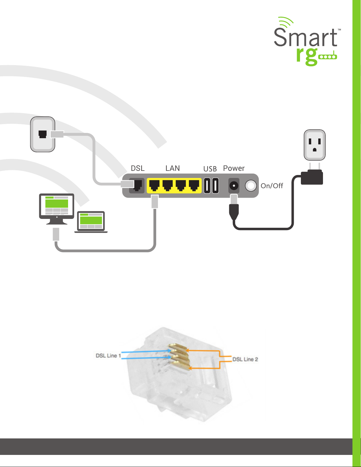
Connections:
Below is a generic representation of a SmartRG gateway, however your specic model may have greater or fewer ports and con-
trols across the back of the unit. Refer to the Quick Start Guide enclosed with your gateway for specics regarding installation of
your particular model.
The ports depicted in this example are described as follows:
DSL
The grey, RJ12 port labeled DSL is specically intended for connection to an internet provider via a DSL (Digital Subscriber Line)
service. The center pair carries the rst DSL line. For models like the SR550n equipped with two DLS ports and bonded DSL capa-
bility, the outer pair carries the second line.
501 SE Columbia Shores Boulevard, Suite 500, Vancouver, Washington 98661, USA l +1 360 859 1780
SmartRG Inc. Propriety and Condential. All Rights Reserved. Copyright © 2014 smartrg.com
Page 8
Page 9

WAN
A stand-alone RJ45 port labeled WAN enables your SmartRG gateway to be hard-wired to another network device with a RJ45/
Ethernet output such as a cable, ber, or DSL modem.
For models with a stand-alone, RJ45, WAN port and a DSL port, the WAN port can be re-purposed to function as an additional LAN
port when your internet connection is via DSL.
See the ETH Interface section of this manual for further instructions to enable this SmartPortTM feature.
LAN
The set of four, RJ45 ports across the back of your gateway labeled LAN1, LAN2, LAN3, LAN4 are the means to connect client
devices such as computers and printers to your gateway.
On some models, one of these four ports may be labeled as WAN indicating SmartPortTM support. SmartPortTM enables a LAN
port to be re-purposed to function as an Ethernet WAN port (describe above). When this port is serving as a LAN port, the corre-
sponding LED on the face of the unit is labeled, “WAN”.
See the ETH Interface section of this manual for further instructions to enable this SmartPortTM feature.
USB
USB ports on SmartRG products currently provide +5 DC volts. Future rmware updates will enable data transfer via USB.
POWER
Use only the power supply included with your gateway. Intended for indoor use only.
External Buttons:
Smart RG gateways provide pushbutton controls on the exterior for critical features. These buttons give you a convenient means
to, trigger WPS mode, toggle the WiFi radio on and off or reset the gateway.
The following describes specics for each of these controls.
WPS Button
Wi-Fi Protected Setup™ (WPS) is standard means for secure connection between your gateway and various wireless client de-
vices. It is designed to simplify the pairing process between devices.
If you have client devices that support WPS, use this to automatically congure wireless security for your network. WPS cong-
ures one client device at a time. Reference the Quick Start Guide included with your gateway for specic instructions. Also see
the Wireless chapter of this manual.
501 SE Columbia Shores Boulevard, Suite 500, Vancouver, Washington 98661, USA l +1 360 859 1780
Page 9
SmartRG Inc. Propriety and Condential. All Rights Reserved. Copyright © 2014 smartrg.com
Page 10

Repeat the steps as necessary for each additional WPS compliant device you wish to connect.
The location of the WPS button varies by model.
• On models SR550n, SR510n, and SR552n, the button is located on the left side of the unit.
• SR360n, locate the WPS button on the top of the unit.
• For the SR350n and SR500n models, an exterior button is not present however WPS is supported via the on-board soft-
ware.
Reference the Quick Start Guide included with your gateway for specic instructions.
WLAN Button
The button labeled WiFi or WLAN (depending on model) toggles the WiFi radio on and off. Refer to the WLAN LED indicator to
determine the current state of the WiFi radio.
The location of the WLAN button varies by model.
• On models SR360n, SR550n, SR510n, SR552n and SR630n, the button is located on the left side of the unit.
• For the SR350n and SR500n models, an exterior button is not present however WPS is supported via the on-board soft-
ware. Reference the Quick Start Guide included with your gateway for specic instructions.
Reset Button
The Reset button is a small hole in the gateway’s enclosure with the actual button mounted behind the surface. This style of push-
button prevents the gateway from being inadvertently reset during handling. Reset must be actuated with a paper clip or similar
implement.
This pin-hole sized reset button has three functions. The duration for which the button is held dictates which function is carried
out.
• Brief, momentary contact performs a modem reset that is equivalent to the Reboot function in the gateway’s software
UI.
• A 5 second hold on the Reset button performs the software UI equivalent to Restore Default.
• Holding reset for 10-15 seconds - the POWER LED goes red and unit enters CFE mode. A state associated with perform-
ing rmware updates via internet browser.
The location of the Reset button varies by model.
501 SE Columbia Shores Boulevard, Suite 500, Vancouver, Washington 98661, USA l +1 360 859 1780
SmartRG Inc. Propriety and Condential. All Rights Reserved. Copyright © 2014 smartrg.com
Page 10
Page 11
• On models SR500n, SR505n, SR510n, SR550n, SR552n and SR630n, the button is located on the rear of the unit.
• For the SR350n, locate the Reset button on the bottom of the unit.
• For the SR360n, locate the Reset button on the left side of the unit.
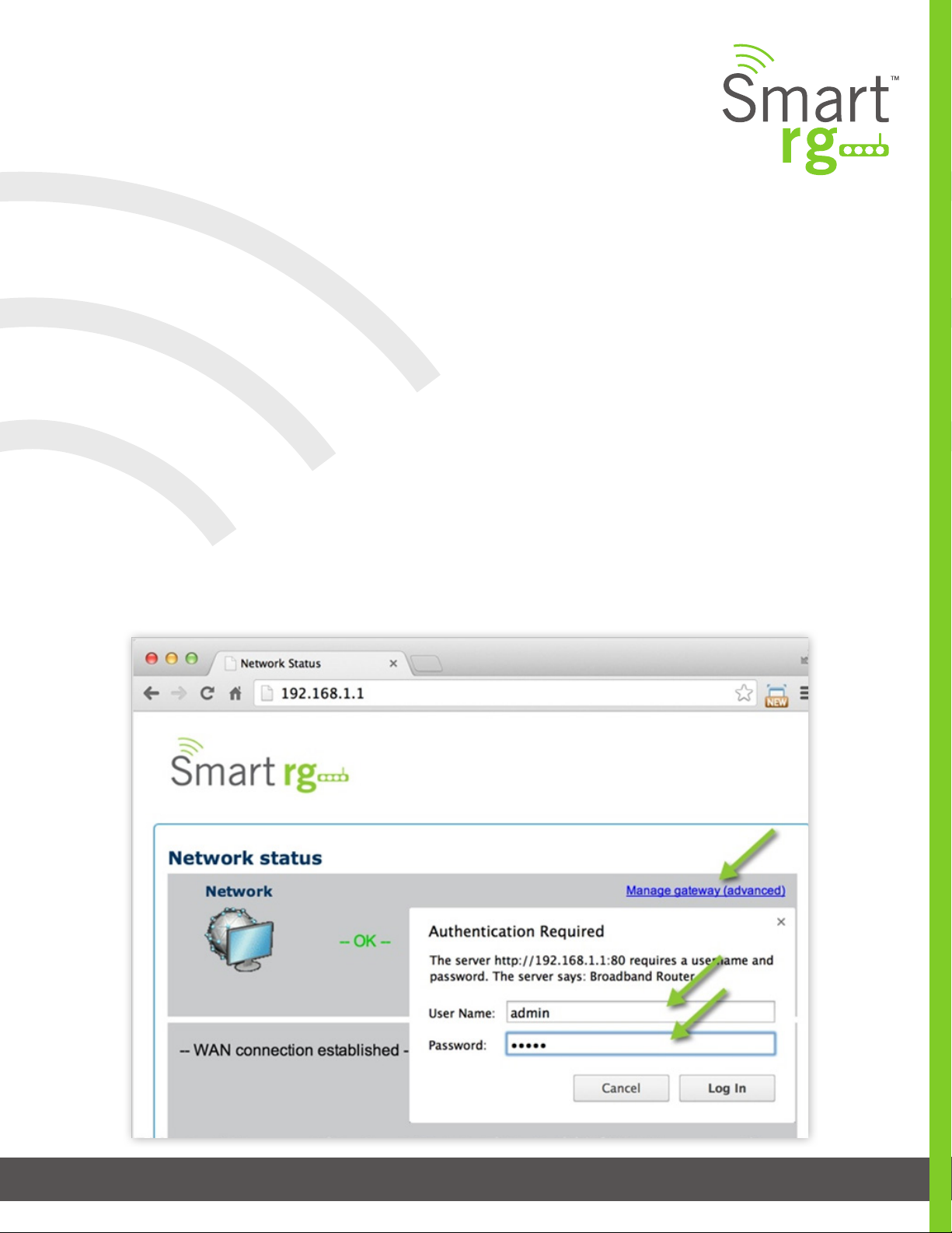
Logging in to Your SmartRG Gateway’s UI
To manually congure the SmartRG Gateway, access the gateway’s embedded web UI:
1. Attach your computer’s RJ45 connection to any of the SmartRG gateway’s LAN ports (1-4)
2. Congure your computer’s IP interface to acquire an IP address using DHCP (See the IMPORTANT note below for in-
structions on logging in to a SmartRG gateway congured for “bridge mode” operation.)
3. Open a browser and enter the gateway’s default address http://192.168.1.1 in the address bar
4. Click the Manage Gateway (Advanced) link in the upper right.
5. Enter the default username and password: admin/admin and click Login to display the Device Info page.
501 SE Columbia Shores Boulevard, Suite 500, Vancouver, Washington 98661, USA l +1 360 859 1780
SmartRG Inc. Propriety and Condential. All Rights Reserved. Copyright © 2014 smartrg.com
Page 11
Page 12

NOTE: The gateway’s UI can be accessed via the WAN connection by entering the WAN IP address in your browser’s address bar
and entering the default username and password: support/support. WAN HTTP access control MUST be enabled to access the
gateway’s UI via the WAN connection. Reference section on Management Access Control for details.
If your SmartRG gateway is congured for “bridge mode” (modem) operation, your PC will NOT be able to acquire an address via
CPE’s DHCP. Instead, manually congure your PC’s interface with an IP address on the default network (e.g. 192.168.1.100).
The balance of this guide is dedicated to a sequential walk-through of the user interface of your gateway. Here you will nd a visual refer-
ence of each screen along with a Description for each of the parameters displayed. Where applicable, a range of valid values is outlined
along with an overview narrative of each screen.
For in depth ”how-to” information for specic scenarios, please take advantage of the knowledge base found at our support web site. Ac-
cess to this site is restricted to SmartRG customers and partners. Do not attempt to share links to this site with your subscribers.
501 SE Columbia Shores Boulevard, Suite 500, Vancouver, Washington 98661, USA l +1 360 859 1780
SmartRG Inc. Propriety and Condential. All Rights Reserved. Copyright © 2014 smartrg.com
Pa g e 12
Page 13

DEVICE INFO
There are nine selections under Device Info. Each of them shows a different element of the gateway’s setup, status or nature of
its connection with the provider and also with LAN devices. Device Info screens are read-only. It is not possible to interact with or
change the settings in this section.
Summary
Upon successful login, Device Info is the rst screen to appear. This is screen is dedicated to the display of hardware and software
details associated with your gateway. In addition, the current status of the WAN connection (if present) is shown.
Wan Info
The Device Info WAN status screen, provides a high level overview for the connection between your Internet Service Provider and
the Gateway device, itself. The WAN interface could physically be DSL or Ethernet and supports a number of Layer 2 and above
conguration options covered later in this document. Some features are supported only on specic Smart RG models. These ex-
ceptions and are specied in this guide.
501 SE Columbia Shores Boulevard, Suite 500, Vancouver, Washington 98661, USA l +1 360 859 1780
SmartRG Inc. Propriety and Condential. All Rights Reserved. Copyright © 2014 smartrg.com
Pa g e 13
Page 14
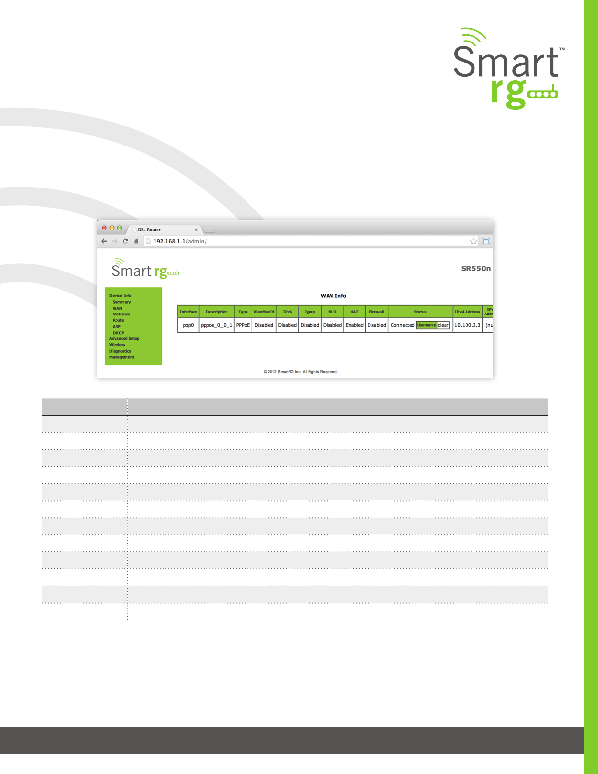
Wan Info
The Device Info -> WAN status screen, provides a high level overview for the connection between your Internet Service Provider
and the Gateway device, itself. The WAN interface could physically be DSL or Ethernet and supports a number of Layer 2 and
above conguration options covered later in this document. Some features are supported only on specic Smart RG models.
These exceptions and are specied in this guide.
Field Name Description
Interface Displays the connection interface (layer 2 interface ( ) through which gateway handles the trac.)
Description Displays the service description (pppoe, ipoe, br)
Type Displays the service type (PPPoE, IPoE, Bridge)
VlanMuxId Displays the VLAN ID (Disabled, 0-4094)
IPv6 Displays the state of IPv6 (Enabled, Disabled)
Igmp Displays the state of IGMP (Enabled, Disabled)
MLD Displays the state of MLD (Enabled, Disabled)
NAT Displays the state of NAT (Enabled, Disabled)
Firewall Displays the state of the Firewall (Enabled, Disabled)
Status Displays the status of the WAN connection (Disconnected, Uncongured, Connecting, Connected)
IPv4 Address Displays the obtained IPv4 address
IPv6 Address Displays the obtained IPv6 address
Statistics
The Statistic screens provide network interface information for LAN, WAN Service, xTM and DSL. All data is updated on a 15 min-
ute interval.
501 SE Columbia Shores Boulevard, Suite 500, Vancouver, Washington 98661, USA l +1 360 859 1780
SmartRG Inc. Propriety and Condential. All Rights Reserved. Copyright © 2014 smartrg.com
Page 14
Page 15
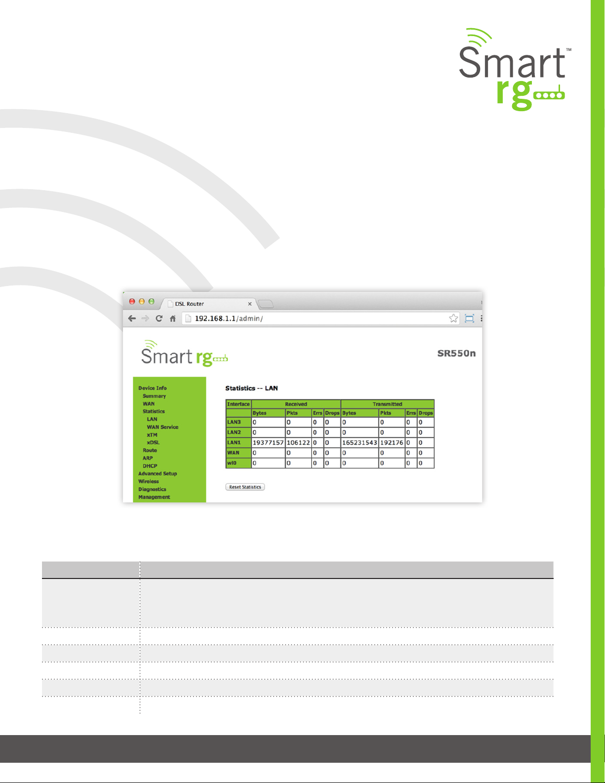
LAN
Device Info -> Statistics -> LAN displays the TX/RX Bytes, Packets, Error and Drops for each LAN interface for your SmartRG
modem. All local LAN Ethernet ports, Ethernet WAN ports and w10(Wireless Interface) for your SmartRG gateway are included.’
Use the Reset Statistics button near the bottom of the screen to reset these counters.
NOTE: Not all SmartRG gateway models support the SmartPort feature wherein a LAN port can be re-purposed to function as a
WAN port (as displayed in the Interface column below note, LAN3, LAN2, LAN1, WAN.) Only models SR5xxn and SR360n support
this functionality.
The individual elds on this screen are dened as follows:
Field Name Description
Interface (Received/
Transmitted)
Interface Displays available LAN interfaces
Bytes Bytes - (RX/ TX) total quantity of packets in Bytes
Pkts Pkts - (RX/ TX) total quantity of packets
Errs Errs - (RX/ TX) total quantity of error packets
Drops Drops - (RX/ TX) total quantity of dropped packets
501 SE Columbia Shores Boulevard, Suite 500, Vancouver, Washington 98661, USA l +1 360 859 1780
SmartRG Inc. Propriety and Condential. All Rights Reserved. Copyright © 2014 smartrg.com
LAN1, LAN2, LAN3, LAN4
Ethernet WAN if congured on your device
Wl0 is the Wireless LAN side Interface
Pa g e 15
Page 16
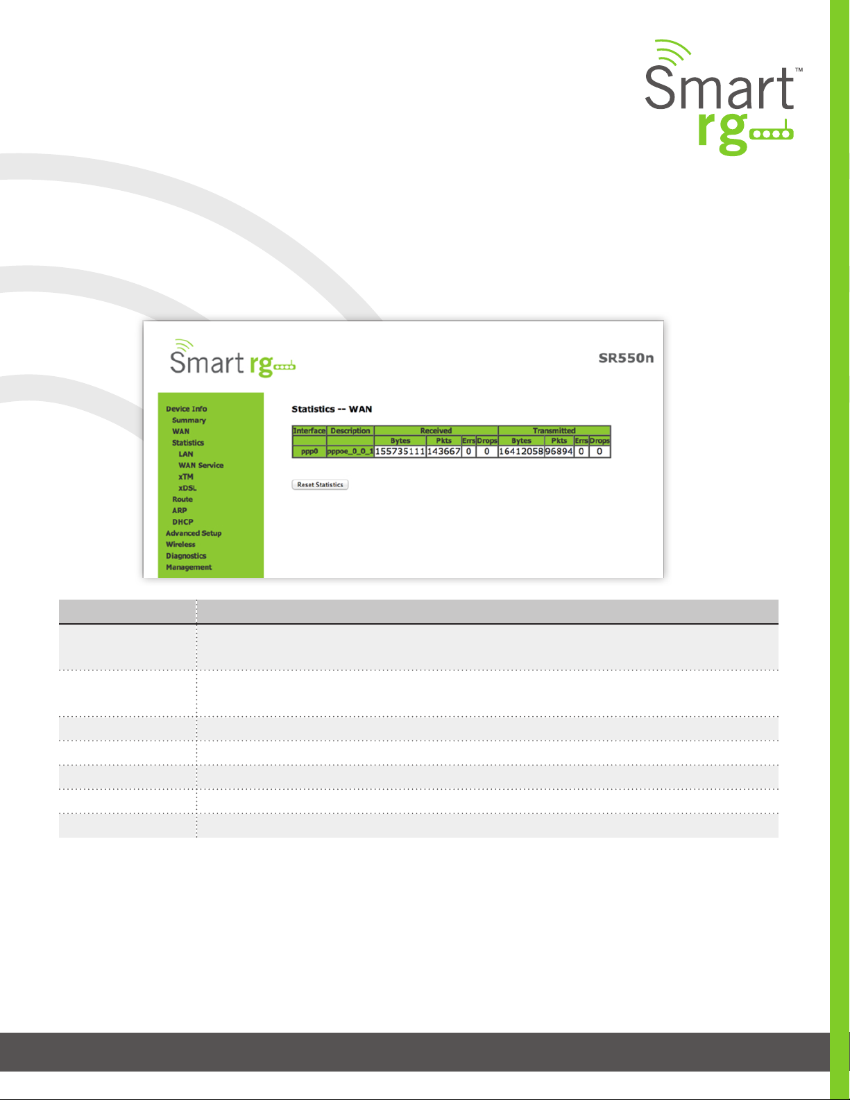
WAN Service
Device Info -> Statistics -> WAN displays the TX/RX Bytes, Packets, Error and Drops for each WAN interface for your SmartRG
Gateway. All WAN interfaces congured for your SmartRG gateway are included.
Use the Reset Statistics button near the bottom of the screen to reset these counters.
Field Name Description
Interface
(RX/ TX)
Description
(RX/ TX)
Reset Statistics Resets the Statistics to zero.
Displays available WAN interfaces (atm, ptm, eth)
Displays the service description (pppoe, ipoe, br)
Bytes - (RX/ TX) total quantity of packets in Bytes
Pkts - (RX/ TX) total quantity of packets
Errs - (RX/ TX) total quantity of error packets
Drops -(RX/ TX) total quantity of dropped packets
501 SE Columbia Shores Boulevard, Suite 500, Vancouver, Washington 98661, USA l +1 360 859 1780
SmartRG Inc. Propriety and Condential. All Rights Reserved. Copyright © 2014 smartrg.com
Pa ge 16
Page 17
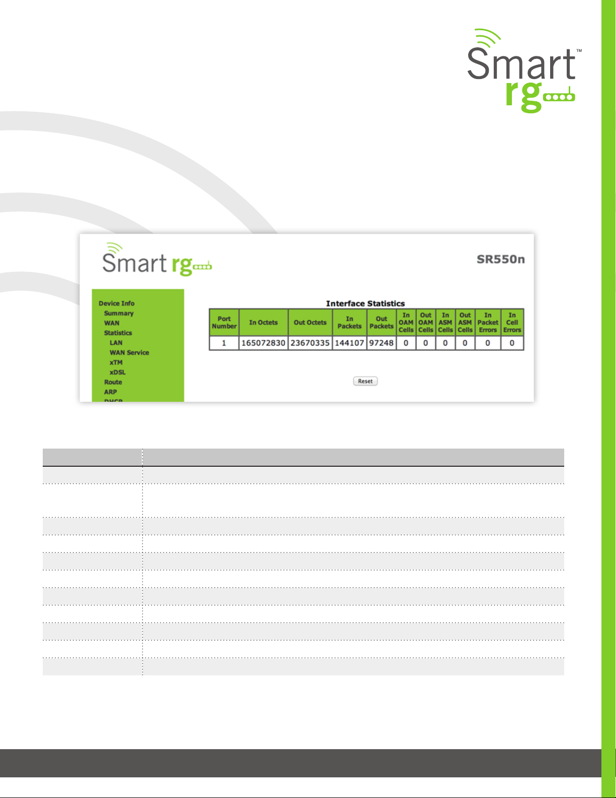
xTM
The Device Info -> Statistics -> xTM displays the ATM/PTM statistics for your SmartRG Gateway. All WAN interfaces congured
for your SmartRG gateway are included.
Use the Reset button near the bottom of the screen to reset these counters.
The individual elds on this screen are dened as follows:
Field Name Description
Port Number Displays the statistics specically for Port 1, or both ports if Bonded
In Octets Total quantity of received Octets
Out Octets Total quantity of transmitted Octets
In Packets Total quantity of received Packets
Out Packets Total quantity of transmitted Packets
In OAM Cells Total quantity of received OAM Cells
Out OAM Cells Total quantity of transmitted OAM Cells
In ASM Cells Total quantity of received ASM Cells
Out ASM Cells Total quantity of transmitted ASM Cells
In Packet Errors Total quantity of received Packet Errors
In Cell Errors Total quantity of received Cell Errors
501 SE Columbia Shores Boulevard, Suite 500, Vancouver, Washington 98661, USA l +1 360 859 1780
SmartRG Inc. Propriety and Condential. All Rights Reserved. Copyright © 2014 smartrg.com
Pa ge 17
Page 18

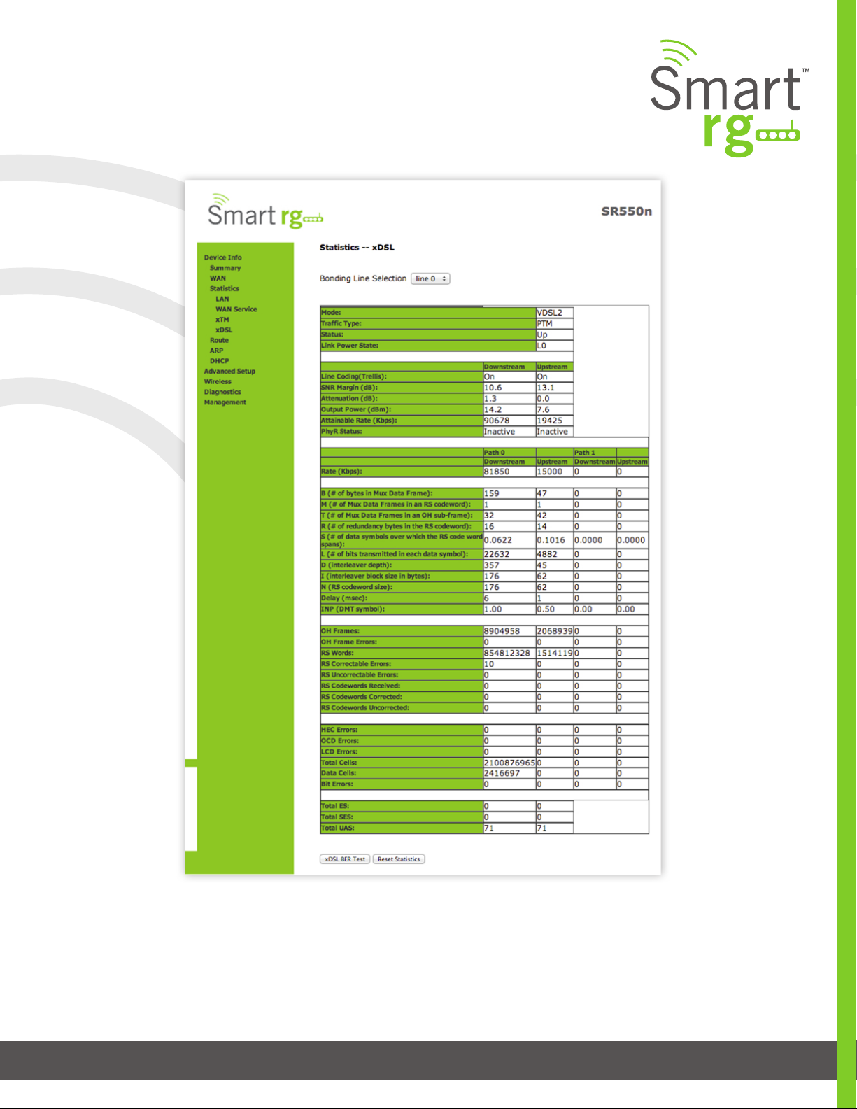
xDSL
Device Info -> Statistics -> xDSL displays the DSL statistics for your SmartRG Gateway. All xDSL
(VDSL or ADSL) interfaces congured for your SmartRG gateway are included.
You are also able to reset these counters by selecting the Reset Statistics button located on the xTM screen as shown below.
Use the Reset Statistics button near the bottom of the screen to reset these counters.
Also featured is an xDSL Bit Error Rate (BER) test which determines the quality of the xDSL connection. Scroll to the bot-
tom of the table of statistics and click xDSL BER Test. The test transfers idle cells containing a known pattern and com-
pares the received data with this known pattern. Comparison errors are then tabulated and displayed. The duration of
the test is selectable from the drop-down menu at the test screen. Selectable values range from 1-360 seconds.
501 SE Columbia Shores Boulevard, Suite 500, Vancouver, Washington 98661, USA l +1 360 859 1780
SmartRG Inc. Propriety and Condential. All Rights Reserved. Copyright © 2014 smartrg.com
Pa ge 18
Page 19
501 SE Columbia Shores Boulevard, Suite 500, Vancouver, Washington 98661, USA l +1 360 859 1780
SmartRG Inc. Propriety and Condential. All Rights Reserved. Copyright © 2014 smartrg.com
Pa ge 19
Page 20

The individual elds on this screen are dened as follows:
Field Name Description
Mode Displays the service type (ADSL_2plus, VDSL2)
Trac Type Displays the connection type (ATM, PTM, ETH
Status Displays the status of the connection (Up, NoSignal, Initializing)
Link Power State Link output power state
Line Coding (Trellis) (Downstream/Upstream) Displays the state of Trellis Coded Modulation (On, Off)
SNR Margin (db) (Downstream/Upstream) Signal to Noise Ratio
Attenuation (db) (Downstream/Upstream) Estimate of average loop attenuation
Output Power (dBm) (Downstream/Upstream) Transmit power from the gateway to the DSL loop.
Attainable Rate (Kbps) (Downstream/ Upstream) The typically obtainable sync rate.
PhyR Status [Inactive, Active] Physical Layer Retransmission feature status. (Downstream/ Upstream)
Rate (Kbps) (Path 0/1, Downstream/Upstream) Current sync rate
MSGc (# of bytes in over-
(Path 0/1, Downstream/Upstream)
head channel message)
B (# of bytes in Mux
(Path 0/1, Downstream/Upstream)
Data Frame)
M (# of Mux Data Frames
(Path 0/1, Downstream/Upstream)
in FEC Data Frame)
T (Mux Data Frames
(Path 0/1, Downstream/Upstream)
over sync bytes)
R (# of check bytes
(Path 0/1, Downstream/Upstream)
in FEC Data Frame)
S (ratio of FEC over PMD
(Path 0/1, Downstream/Upstream)
Data Frame length)
L (# of bits in PMD
(Path 0/1, Downstream/Upstream)
Data Frame)
D (interleaver depth) (Path 0/1, Downstream/Upstream)
Delay (msec) (Path 0/1, Downstream/Upstream)
INP (DMT symbol) (Path 0/1, Downstream/Upstream)
Super Frames (Path 0/1, Downstream/Upstream) Total number of super frames.
501 SE Columbia Shores Boulevard, Suite 500, Vancouver, Washington 98661, USA l +1 360 859 1780
SmartRG Inc. Propriety and Condential. All Rights Reserved. Copyright © 2014 smartrg.com
Page 20
Page 21

Field Name Description
Super Frame Errors (Path 0/1, Downstream/Upstream)
Total number of super frames received with errors.
RS Words (Path 0/1, Downstream/Upstream)
Total number of Reed-Solomon code errors.
RS Correctable Errors (Path 0/1, Downstream/Upstream)
Total number of Reed-Solomon with correctable errors.
RS Uncorrectable Errors (Path 0/1, Downstream/Upstream)
Total number of Reed-Solomon with uncorrectable errors.
RS Codewords Received (Path 0/1, Downstream/Upstream)
Total number of Reed-Solomon Codewords received.
RS Codewords Corrected (Path 0/1, Downstream/Upstream)
Total number of Reed-Solomon Codewords corrected.
RS Codewords
(Path 0/1, Downstream/Upstream) Total number of Reed-Solomon Codewords Uncorrected
Uncorrected
HEC Errors (Path 0/1, Downstream/Upstream) Total number of Header Error Checksum errors
OCD Errors (Path 0/1, Downstream/Upstream) Total number of Out-of-Cell Delineation errors
LCD Errors (Path 0/1, Downstream/Upstream) Total number of Loss of Cell Delineation errors
Total Cells (Path 0/1, Downstream/Upstream) Total number of Cells
Data Cells (Path 0/1, Downstream/Upstream) Total number of Data Cells
Bit Errors (Path 0/1, Downstream/Upstream) Total number of Bit errors
Total ES (Downstream/Upstream) Total number of Errored Seconds
Total SES (Downstream/ Upstream) Total number of Severely Errored Seconds
Total UAS (Downstream/Upstream) Total number of Unavailable Seconds
501 SE Columbia Shores Boulevard, Suite 500, Vancouver, Washington 98661, USA l +1 360 859 1780
SmartRG Inc. Propriety and Condential. All Rights Reserved. Copyright © 2014 smartrg.com
Page 21
Page 22
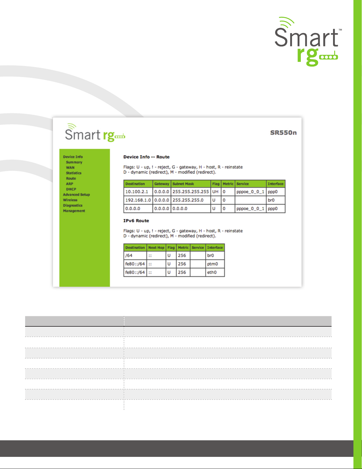
Route
The Device Info -> Route displays the LAN and WAN route table information cong-
ured in your SmartRG Gateway for both IPv4 and IPv6 implementation.
The individual elds on this screen are dened as follows:
Field Name Description
Destination (Including IPv6 Route) Displays the Destination IP addresses.
Gateway Displays the Gateway IP address.
Subnet Mask Displays the Subnet Masks.
Flag (Including IPv6 Route) Displays the status of the ags.
Metric (Including IPv6 Route) Displays the number of hops to reach the default gateway.
Service (Including IPv6 Route) Displays the service type.
Interface (Including IPv6 Route) Displays the WAN/LAN interface.
Next Hop (IPv6 Route only) Displays the next hop IP address.
501 SE Columbia Shores Boulevard, Suite 500, Vancouver, Washington 98661, USA l +1 360 859 1780
SmartRG Inc. Propriety and Condential. All Rights Reserved. Copyright © 2014 smartrg.com
Page 22
Page 23

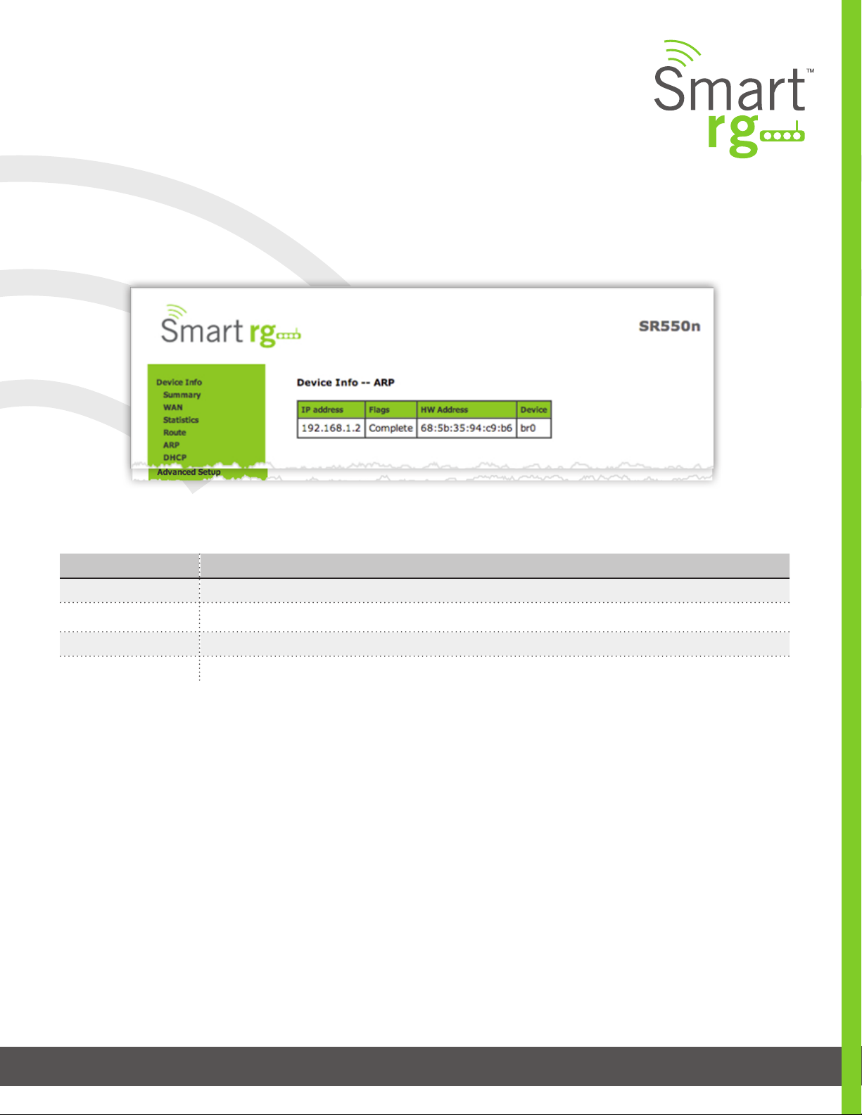
ARP
Device Info -> ARP displays the host IP addresses and their hardware (MAC) addresses for each LAN Cli-
ent connected to the SmartRG Gateway via a LAN Ethernet port or Wireless LAN.
The individual elds on this screen are dened as follows:
Field Name Description
IP address The IP address of the host.
Flags [Complete, Permanent, Published] Each entry in the ARP cache will be marked with one of these ags.
HW Address The hardware (MAC) address of the host.
Device [br(n), atm(n), eth(n), atm(n)] The system level interface by which the host is connected.
501 SE Columbia Shores Boulevard, Suite 500, Vancouver, Washington 98661, USA l +1 360 859 1780
SmartRG Inc. Propriety and Condential. All Rights Reserved. Copyright © 2014 smartrg.com
Page 23
Page 24
DHCP
Device Info -> DHCP displays a list of locally connected LAN hosts and their DHCP lease status, which
are directly connected to the SmartRG Gateway via a LAN Ethernet port or Wireless LAN.
The individual elds on this screen are dened as follows:
Field Name Description
Hostname Displays the Host name of each connected LAN device.
MAC Address Displays the MAC Address for each connected LAN device.
IP Address Displays the IP Address for each connected LAN device.
Expires In Displays the time until the DHCP lease expires for each LAN device.
501 SE Columbia Shores Boulevard, Suite 500, Vancouver, Washington 98661, USA l +1 360 859 1780
SmartRG Inc. Propriety and Condential. All Rights Reserved. Copyright © 2014 smartrg.com
Page 24
Page 25

ADVANCED SETUP
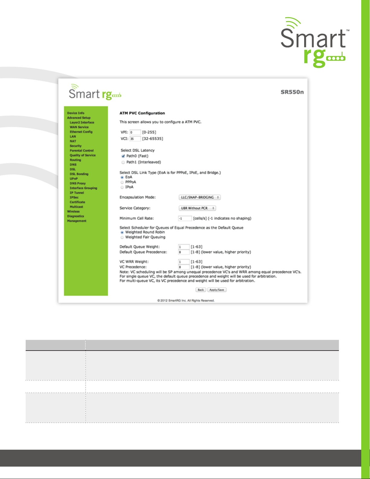
Layer2 Interface
ATM Interface
From this screen you can congure Asynchronous Transfer Mode / Permanent Virtual Conduit for your gateway. You can custom-
ize latency options, Link Type, Encapsulation mode and more. Note that devices (routers) on both ends of the connection must
support ATM / PVC.
ATM is becoming popular as a wide-area network (WAN) medium. ATM offers small cell size and strict quality of service, allowing
voice, video, and data to coexist.
Terms:
VPI – Virtural Path Identier
VCI – Virtual Circuit Identier
VC – Virtual Circuit
After selecting Advanced Setup -> Layer2 Interface -> ATM Interface from the left navigation bar, click Add in the center pane. The
following screen will appear. When your desired settings have been declared, click the Apply/Save button to commit your changes.
501 SE Columbia Shores Boulevard, Suite 500, Vancouver, Washington 98661, USA l +1 360 859 1780
SmartRG Inc. Propriety and Condential. All Rights Reserved. Copyright © 2014 smartrg.com
Page 25
Page 26
The individual elds on this screen are dened as follows:
Field Name Description
VPI [0-255] Enter a Virtual Path Identier. VPI is an 8bit identier to uniquely identify a network path for
ATM cell packets to reach its destination. Every ATM path requires a unique VPI number to associate.
Works together with the VCI. Each individual DSL circuit cannot have the same VPI/VCI combination.
VCI [32-65535] Enter a Virtual Channel Identier. VCI is a 16bit identier that has a unique channel.
Select DSL Latency [Path0 Fast] No error correction and can provide lower latency on error free lines.
[Path1 Interleaved] Error checking that provides error free data which increases latency.
[Path0&1 Both] Fast & Interleaved
501 SE Columbia Shores Boulevard, Suite 500, Vancouver, Washington 98661, USA l +1 360 859 1780
SmartRG Inc. Propriety and Condential. All Rights Reserved. Copyright © 2014 smartrg.com
Page 26
Page 27

Field Name Description
Link Type [EoA] Ethernet over ATM
[PPPoA] Point-to-Point Protocol over ATM
[IPoA] Internet Protocol over ATM
Encapsulation Mode [LLC/SNAP-BRIDGING] Logical Link Control used to carry multiple protocols in a single PVC (Permanent
Virtual Circuit).
[VC/MUX] Virtual Circuit Multiplexer creates a virtual connection used to carry one protocol per PVC
(Permanent Virtual Circuit).
Service Category [UBR without PCR] Unspecied Bit Rate with no Peak Cell Rate, ow control or time synchronization
between the trac source and destination. Commonly used with applications that can tolerate data /
packet loss.
[UBR with PCR] Same as above but with a Peak Cell Rate.
[CBR] Constant Bit Rate relies on timing synchronization to make the network trac predictable. Used
commonly in Video and Audio trac network applications.
[NON Realtime VBR] Non Realtime Variable Bit Rate used for connections that trans-
port trac at a Variable Rate but need to have a guaranteed bandwidth and latency. This
category does not rely on timing synchronization between the destination and source.
[Realtime VBR] Realtime Variable Bit Rate. Same as above but relies on timing and synchronization
between the destination and source. Commonly used in networks with compressed video trac.
Minimum Cell Rate [cells/s] (-1 indicates no shaping)
Minimum allowable rate at which cells can be sent on a ATM network.
Scheduler for Queues
of Equal Precedence
as the Default Queue
The algorithm used to schedule the queue behavior.
[WRR] Weighted Round Robin packets are accessed in a round robin style and classes can be given.
[WFQ] Weighted Fair Queuing packets are assigned in a specic queue.
Default Queue Weight [1-63] The default weight of the specied queue.
Default Queue Precedence [1-8] The Precedence of the specied group.
VC scheduling is unique from Default Queue’s.
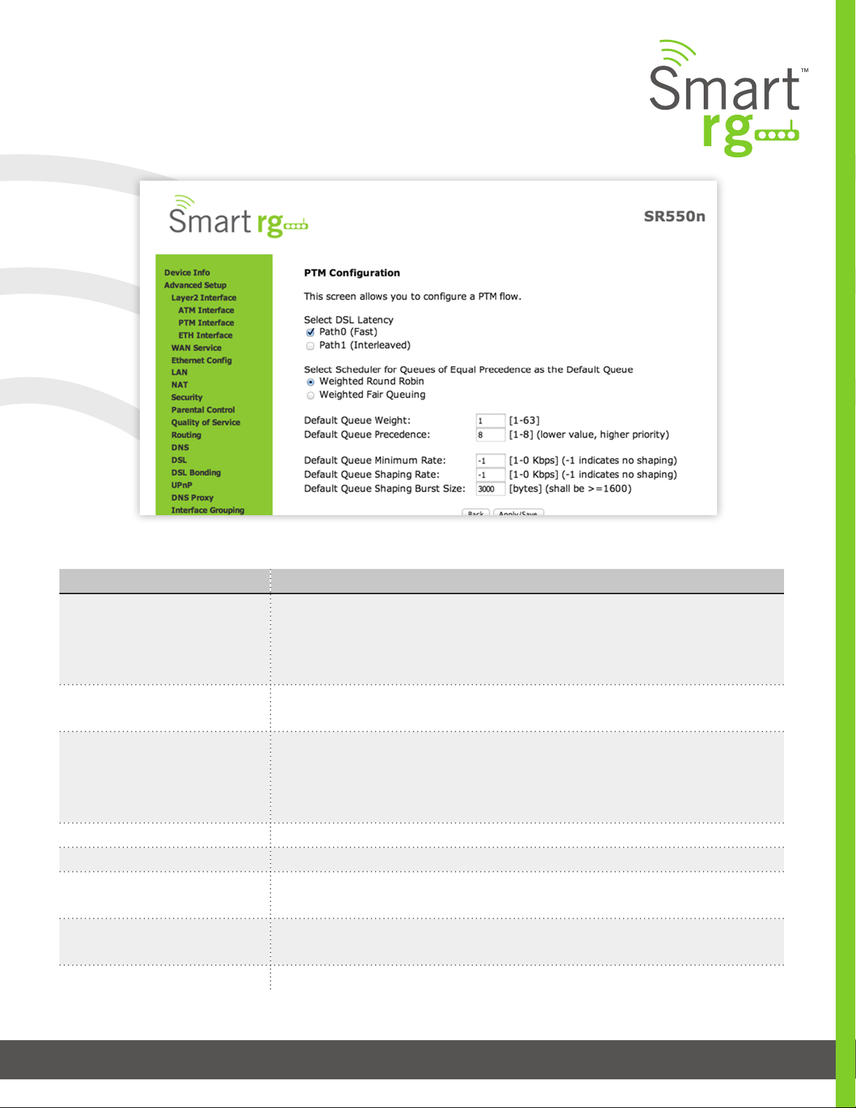
PTM Interface
The SmartRG gateway’s VDSL2 standards support Packet Transfer Mode (PTM). An alternative to ATM mode, PTM transports
packets (IP, PPP, Ethernet, MPLS, and others) over DSL links. Reference the IEEE802.3ah standard for Ethernet in the First Mile
(EFM) for additional information.
After selecting Advanced Setup -> Layer2 Interface -> PTM Interface from the left navigation bar, click Add in the center pane. The
following screen will appear.
When your desired settings have been entered, click the Apply/Save button to commit your changes.
501 SE Columbia Shores Boulevard, Suite 500, Vancouver, Washington 98661, USA l +1 360 859 1780
SmartRG Inc. Propriety and Condential. All Rights Reserved. Copyright © 2014 smartrg.com
Page 27
Page 28
The individual elds on this screen are dened as follows:
Field Name Description
Select DSL Latency [Path0 Fast] No error correction and can provide lower latency on error free lines.
[Path1 Interleaved] Error checking that provides error free data. This tends to increases
latency.
[Path0&1 Both] Fast & Interleaved.
Weighted Round Robin Time slices are assigned to each process in equal portions and in circular order, handling
all processes without priority (also known as cyclic executive).
Weighted Fair Queuing A data packet scheduling technique allowing different scheduling priorities to statistically
multiplexed data ows. Since each data ow has its own queue, an ill-behaved ow (who
has sent larger packets or more packets per second than the others since it became ac-
tive) will only punish itself and not other sessions.
Default Queue Weight [1-63] Enter a default weight of the specied queue.
Default Queue Precedence [1-8] Enter a precedence for the the specied queue.
Default Queue Minimum Rate [1-0 Kbps] The default minimum rate at which trac can pass through the queue.
[-1 Indicates no shaping.]
Default Queue Shaping Rate [1-0 Kbps] The shaping rate for the specied queue.
[-1 Indicates no shaping.]
Default Queue Shaping Burst Rate [>= 1600] The maximum rate at which trac can pass through the queue.
501 SE Columbia Shores Boulevard, Suite 500, Vancouver, Washington 98661, USA l +1 360 859 1780
SmartRG Inc. Propriety and Condential. All Rights Reserved. Copyright © 2014 smartrg.com
Page 28
Page 29
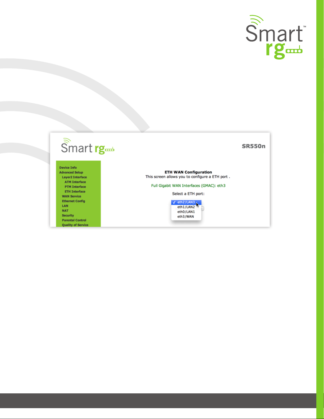
ETH Interface
Your gateway has four LAN ports. One of them can be re-purposed to become a WAN port when such an RJ45 WAN port is desired.
After selecting Advanced Setup -> Layer2 Interface -> ETH Interface from the left navigation bar, click Add in the center pane. The
following screen will appear. From the drop-down menu in the center pane, simply select the LAN port you wish to act as a WAN
port.
WAN Service
There are several variations of WAN Service available to congure. The three core variations are:
• PPP over Ethernet (PPPoE)
• IP over Ethernet
• Bridging
This chapter will illustrate a sample conguration scenario down each of these three variations and dene the available elds to
customize your WAN service setup.
PPP over Ethernet
After selecting Advanced Setup -> WAN Service from the left navigation bar, click the Add button. A progression of several screens
will follow. Advance to the next after completing the required elds using the Next button appearing near the bottom of each
screen.
501 SE Columbia Shores Boulevard, Suite 500, Vancouver, Washington 98661, USA l +1 360 859 1780
SmartRG Inc. Propriety and Condential. All Rights Reserved. Copyright © 2014 smartrg.com
Page 29
Page 30
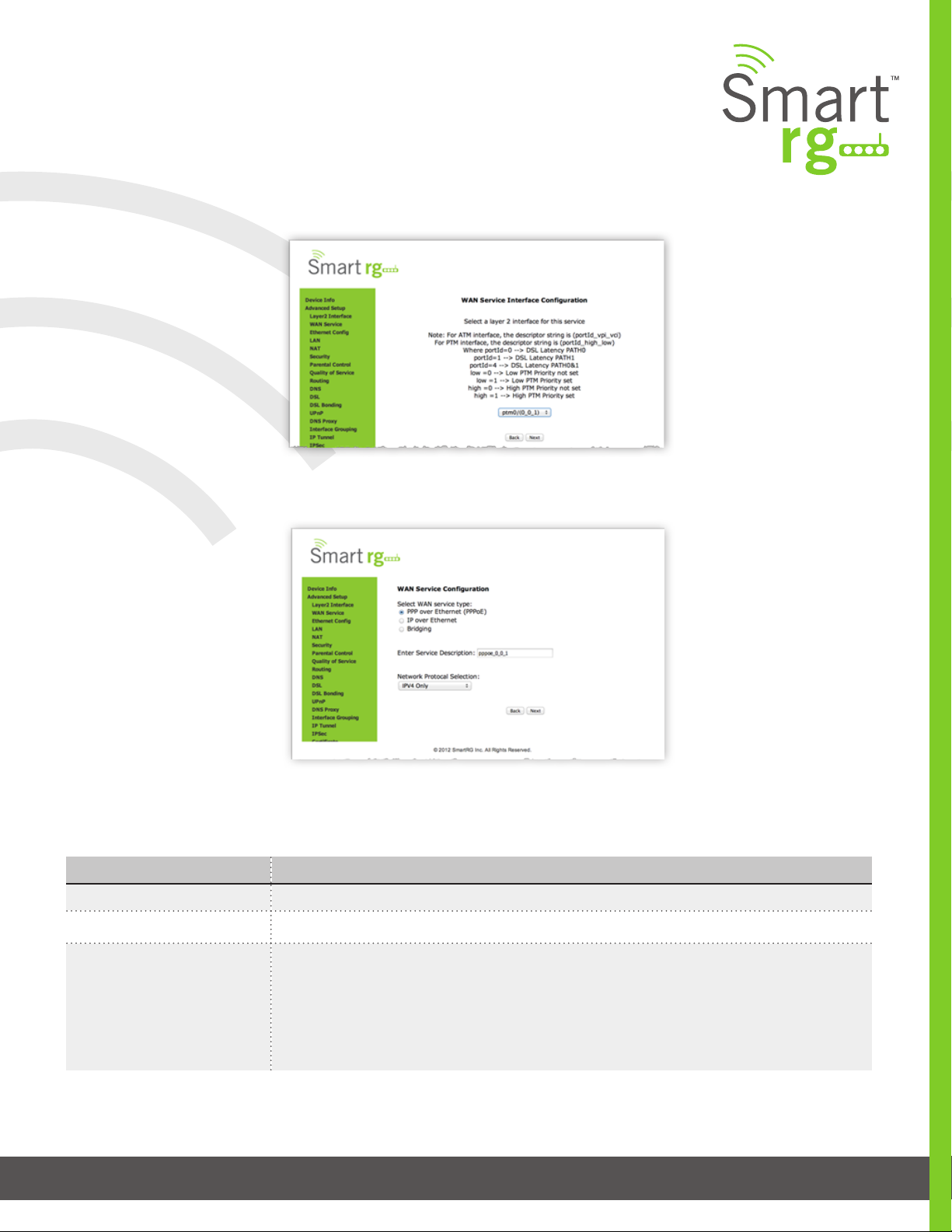
First, select the Layer2 interface to use for the WAN service.
Click the Next button to advance to the next step.
Next, select the type of WAN service you wish to create.
For this example choose PPP over Ethernet.
Click Next after completing the necessary elds.
The individual elds on this screen are dened as follows:
Field Name Description
WAN service type [PPP over Ethernet PPPOE, IP over Ethernet IPoE, Bridging]
Enter Service Description Enter a name to describe this conguration.
Network Protocol Selection A data packet scheduling technique allowing different scheduling priorities to statistically mul-
tiplexed data ows. Since each data ow has its own queue, an ill-behaved ow (who has sent
larger packets or more packets per second than the others since it became active) will only
punish itself and not other sessions.
Next, congure the PPP Username, Password and related information.
501 SE Columbia Shores Boulevard, Suite 500, Vancouver, Washington 98661, USA l +1 360 859 1780
SmartRG Inc. Propriety and Condential. All Rights Reserved. Copyright © 2014 smartrg.com
Page 30
Page 31

501 SE Columbia Shores Boulevard, Suite 500, Vancouver, Washington 98661, USA l +1 360 859 1780
SmartRG Inc. Propriety and Condential. All Rights Reserved. Copyright © 2014 smartrg.com
Page 31
Page 32

Click Next after completing the necessary elds.
The individual elds on this screen are dened as follows:
Field Name Description
PPP Username: Enter the Username required for authentication to the PPP server.
PPP Password: Enter the Password required for authentication to the PPP server.
PPPoE Service Name: (Optional) Enter a description for this service.
Authentication Method Select a means for authentication from the drop-down list.
[AUTO] Attempt to AUTO detect handshake protocol in list below.
[PAP] Password Authentication Protocol (plaintext passwords)
[CHAP] Challenge Handshake Authentication Protocol. (MD5 hashing scheme on passwords)
[MSCHAP] Microsoft Challenge Handshake Authentication Protocol. (Microsoft encrypted
password authentication protocol)
CP Keepalive Period The frequency with which the keepalive packet is sent by the gateway to the PPP server.
LCP Retry Threshold In the event that the PPP server does not respond to the Keepalive, how many additional at-
tempted packets will the gateway send before giving up and declaring the connection, Failed.
Dial on Demand [1-4320] Enables Inactivity Timeout (minutes). Default = 0 (not applicable.)
Connection automatically starts when there is outbound trac to the Internet. It automati-
cally terminates if the connection is idle based on the value in the Idle Timeout setting.
PPP IP Extension Forward all trac to Advanced DMZ IP specied in the next eld.
Advanced DMZ Only applicable if PPP IP extension is selected. Specify IP to forward trac PPPoE trac to.
Use Static IPv4 Address Specify IPv4 Address to apply to WAN service.
Retry PPP password on
[1-65536] Max PPP authentication retries on failure. (65536=Forever)
authentication error
Enable PPP Debug Mode The system will put more PPP connection information into the system log of the device. This is
for debugging errors and not for normal usage.
Bridge PPPoE Frames Be-
tween WAN and Local Ports
PPPoE passthrough to relay PPPoE connections from behind the modem. Also known as Half-
Bridged mode.
Enable Firewall Enables functions in the Security sub-menu
Enable NAT Enable sharing the WAN interface across multiple devices on the LAN. Also enables the func-
tions in the NAT sub-menu and addition PPPoE NAT features to select.
501 SE Columbia Shores Boulevard, Suite 500, Vancouver, Washington 98661, USA l +1 360 859 1780
SmartRG Inc. Propriety and Condential. All Rights Reserved. Copyright © 2014 smartrg.com
Page 32
Page 33

Field Name Description
-Enable Fullcone NAT Enables what is known as one-to-one NAT. (Exposed when Enable NAT is checked.)
-Enable SIP Enables Session Initiation Protocol (SIP) pass-through NAT. Used for Voice over IP (VOIP) ap-
plications. (Exposed when Enable NAT is checked.)
Enable IGMP Multicast Proxy Enables Internet Group Membership Protocol (IGMP) multicast. Used by IPv4 hosts to report
multicast group memberships to any neighboring multicast routers.
No Multicast VLAN Filter Disables multicast ltering between WAN and LAN (VlanMux) network.
MTU size [1370-1492] Edit the Maximum Transmission Units (MTU) for PPP service.
Use Base MAC Address
on this WAN interface
ADDITIONAL OPTIONS
WHEN IPV4&IPV6 or IPV6
Only are selected at the WAN
Service Creation Page
Use SmartRG Devices Base (Primary) MAC address. When unchecked a unique MAC per ser-
vice is assigned.
Enable IPv6 Unnumbered Model
Enable IPv6 Unnumbered Model
Launch Dhcp6c for Address Assignment (IANA)
Launch Dhcp6c for Prex Delegation (IAPD)
Enable MLD Multicast Proxy
Next, Select the interface used as a default gateway used for the PPP service being created.
Use the -> button to move your highlighted selection from left to right or <- for right to left
Click Next after completing the necessary elds.
501 SE Columbia Shores Boulevard, Suite 500, Vancouver, Washington 98661, USA l +1 360 859 1780
SmartRG Inc. Propriety and Condential. All Rights Reserved. Copyright © 2014 smartrg.com
Page 33
Page 34

Select DNS Server Interface from available WAN interfaces.
Use the -> button to move your highlighted selection from left to right or <- for right to left.
Alternatively, you may use the lower portion of the screen to manually key in static DNS IP addresses.
Click Next after completing the desired parameters.
Lastly, the summary screen will appear indicating that your PPPoE WAN setup is complete.
Review the summary and either click Apply/Save to commit your changes or choose Back to step through this progression of
screens in reverse order to make any necessary alterations you may desire.
501 SE Columbia Shores Boulevard, Suite 500, Vancouver, Washington 98661, USA l +1 360 859 1780
SmartRG Inc. Propriety and Condential. All Rights Reserved. Copyright © 2014 smartrg.com
Page 34
Page 35

IP Over Ethernet
The next WAN Service variant is IP over Ethernet.
After selecting Advanced Setup -> WAN Service from the left navigation bar, click the Add button. A progression of several screens
will follow. Advance to the next after completing the required elds using the Next button appearing near the bottom of each
screen.
First, select the Layer2 interface to use for the WAN service.
Click the Next button to advance to the next step.
Next, select the type of WAN service you wish to create.
For this example choose IP over Ethernet.
Click Next after completing the necessary elds.
The individual elds on this screen are dened as follows:
Field Name Description
WAN service type [PPP over Ethernet PPPOE, IP over Ethernet IPoE, Bridging]
Enter Service Description Enter a name to describe this conguration.
Network Protocol Selection [IPV4 Only]
[IPV4&IPV6] (Dual Stack) – IPV4 and IPV6 running concurrently.
[IPV6 Only]
Note: When selecting IPV4&IPV6 or IPV6 the subsequent options presented will change ac-
cordingly.
501 SE Columbia Shores Boulevard, Suite 500, Vancouver, Washington 98661, USA l +1 360 859 1780
SmartRG Inc. Propriety and Condential. All Rights Reserved. Copyright © 2014 smartrg.com
Page 35
Page 36

Enter the relevant WAN IP Settings.
Click Next after completing the necessary elds.
The individual elds on this screen are dened as follows:
Field Name Description
WAN service type [PPP over Ethernet PPPOE, IP over Ethernet IPoE, Bridging]
Enter Service Description Enter a name to describe this conguration.
Network Protocol Selection [IPV4 Only]
[IPV4&IPV6] (Dual Stack) – IPV4 and IPV6 running concurrently.
[IPV6 Only]
Note: When selecting IPV4&IPV6 or IPV6 the subsequent options presented will change ac-
cordingly.
501 SE Columbia Shores Boulevard, Suite 500, Vancouver, Washington 98661, USA l +1 360 859 1780
SmartRG Inc. Propriety and Condential. All Rights Reserved. Copyright © 2014 smartrg.com
Page 36
Page 37

Enter the relevant WAN IP Settings.
Click Next after completing the necessary elds.
The individual elds on this screen are dened as follows:
Field Name Description
Obtain an IP address automatically When you wish the ISP to automatically assign the WAN IP to the gateway.
Option 60 Vendor ID (Optional)
Broadcast a specic vendor ID for the DHCP server to accept the device.
Option 61 IAID (Optional)
Interface Association Identier (IAID). A unique identier for an IA, chosen by the client.
Option 61 DUID (Optional)
DHCP Unique Identier (DUID) is used by the client to get an IP address from the DHCP server.
Use the following Static IP address
WAN IP Address
WAN Subnet Mask
WAN gateway IP address
Use this section to manually declare the Static IP information provided by your ISP.
Enter the static WAN IPV4 Address.
Enter the static Subnet Mask.
Enter the static Gateway IP address.
501 SE Columbia Shores Boulevard, Suite 500, Vancouver, Washington 98661, USA l +1 360 859 1780
SmartRG Inc. Propriety and Condential. All Rights Reserved. Copyright © 2014 smartrg.com
Page 37
Page 38

Field Name Description
Advanced DMZ (Optional) Check this option to enable Advanced DMZ on the WAN service.*
NON DMZ IP Address (Optional)
Broadcast a specic vendor ID for the DHCP server to accept the device.
NON DMZ Net Mask Enter a secondary LAN IP address for the gateway. e.g. 192.168.2.1
Obtain an IPv6 address automatically
When you wish the ISP to automatically assign the WAN IP to the gateway.
Dhcpv6 Address Assignment (IANA) Select this option for CPE to receive WAN IP from ISP.
Dhcpv6 Prex Delegation (IAPD) Select this option for CPE to generate WAN IP’s prex from server rest by MAC address.
Use the following Static IPv6 address Use this section to manually declare v6 the Static IP information provided by your ISP.
WAN IPv6 Address/Prex Length Enter the IP address / prex length
WAN Next-Hop IPv6 Address Enter the IP address of
* For additional info see the SmartRG Support site’s knowledgebase.
Enter the NAT Settings.
No selections are required. All settings are optional.
501 SE Columbia Shores Boulevard, Suite 500, Vancouver, Washington 98661, USA l +1 360 859 1780
SmartRG Inc. Propriety and Condential. All Rights Reserved. Copyright © 2014 smartrg.com
Page 38
Page 39

Click Next after completing the necessary elds.
The individual elds on this screen are dened as follows:
Field Name Description
Interface Address (prex length is
IPV6 address to assign as the gateways Local LAN IPV6 address and prex length.
required)
Enable DHCP v6 Server Check this option to turn on the DHCP v6 feature on the LAN.
Enable DHCP Server
Inherit IPV6 address assignments from the WAN IPV6 interface.
- Stateless
Enable DHCP Server
DHCPv6 server given by the LAN IPV6 network as congured with additional options.
- Stateful
Start interface ID: Enter the beginning IPv6 available addresses for DHCP to assign to LAN
devices.
End interface ID: Enter the ending IPv6 available addresses for DHCP to assign to LAN
devices.
Leased Time (hour): Amount of time before a new IPv6 lease is requested by the LAN cli-
ent.
Enable RADVD (Optional)
Router Advertisement Daemon (RADVD) service that sends router advertisements to LAN
clients.
Enable ULA Prex Advertisement- Check this option to enable unique local address (ULA)
advertisement on the LAN.
Randomly Generate- Select this option to enable the gateway to generate a random IPv6
prex.
Statically Congure- Select this option to manually congure a static IPv6 prex.
Enable MLD Snooping (Optional)
Multicast Listener Discovery (MLD) snooping manages the IPV6 multicast trac.
Standard Mode: Multicast trac will ood to all bridge ports when no client subscribes to
a multicast group – even if IGMP snooping is enabled.
Blocking Mode: The multicast data trac will be blocked and not ood to all bridge ports
when there are no client subscriptions to any multicast group.
501 SE Columbia Shores Boulevard, Suite 500, Vancouver, Washington 98661, USA l +1 360 859 1780
SmartRG Inc. Propriety and Condential. All Rights Reserved. Copyright © 2014 smartrg.com
Page 39
Page 40

NAT
Virtual Servers (Port Forward)
Virtual Servers (more commonly known as Port Forward) is a technique used to facilitate communications by external hosts with
services provided within a private local area network.
After Selecting Advanced Setup -> NAT -> Virtual Servers from the left navigation bar, click the Add button. The following screen
will appear. Customize the elds to create your port forwarding entry.
Click Apply/Save to commit your changes.
501 SE Columbia Shores Boulevard, Suite 500, Vancouver, Washington 98661, USA l +1 360 859 1780
SmartRG Inc. Propriety and Condential. All Rights Reserved. Copyright © 2014 smartrg.com
Page 40
Page 41

The individual elds on this screen are dened as follows:
Field Name Description
Use Interface Select the WAN interface that this NAT rule will apply to.
Select a Service Select from a list of common applications that typically require port forwards in place.
The port ranges and protocol elds will be pre-populated
Custom Service If your application does not appear in the preceding drop-down list you may manually en-
ter a unique name for the application.
Server IP Address IP address of the LAN client in which the service has been hosted.
External Port Start External Port to start with
External Port End External Port to end with
Protocol Protocol used Transmission Control Protocol (TCP) or User Datagram Protocol (UDP) or TCP/UDP
Internal Port Start Internal Port to start with
Internal Port End Internal Port to end with
Port Triggering
Some applications require that specic ports in the gateway’s rewall be opened for access by remote parties. Port Trigger dy-
namically opens up the ‘Open Ports’ in the rewall when an application on the LAN initiates a TCP/UDP connection to a remote
party using the Triggering Ports. The Router allows the remote party from the WAN side to establish new connections back to the
application on the LAN side using the Open Ports.
After selecting Advanced Setup -> NAT -> Port Triggering from the left navigation bar, click the Add button. Customize the elds
as needed for the rewall pinholes you wish to establish.
A maximum 96 entries can be congured.
Click Apply/Save to commit your changes.
501 SE Columbia Shores Boulevard, Suite 500, Vancouver, Washington 98661, USA l +1 360 859 1780
Page 41
SmartRG Inc. Propriety and Condential. All Rights Reserved. Copyright © 2014 smartrg.com
Page 42

The individual elds on this screen are dened as follows:
Field Name Description
Use Interface Select the interface over which the port triggering rule will apply.
Select an Application Choose from this list of applications which commonly require a Port trigger entry.
Custom Application A free form text eld. Enter a unique name for the application for which you are creating a
Port Trigger entry
Trigger Port Start [1-65535] An outgoing trigger port number. Set the beginning of the range of available ports.
Trigger Port End [1-65535] An outgoing trigger port number. Set the end of the range of available ports.
Trigger Protocol [TCP, UDP, TCP/UDP] Select the protocol required by the application that will be using the
ports in the specied range.
Open Port Start [1-65535] An incoming port number. Set the beginning of the range of available ports.
Open Port End [1-65535] An incoming port number. Set the end of the range of available ports.
Open Protocol [TCP, UDP, TCP/UDP] Select the protocol from the drop down list.
501 SE Columbia Shores Boulevard, Suite 500, Vancouver, Washington 98661, USA l +1 360 859 1780
SmartRG Inc. Propriety and Condential. All Rights Reserved. Copyright © 2014 smartrg.com
Page 42
Page 43

DMZ Host
The Broadband Router will forward IP packets from the WAN that do not belong to any of the applications congured in the Virtual
Servers table to the DMZ host computer. If it is desired to route all internet trac with no ltering or security to a specic LAN
device, add the IP address of that device to this eld.
After selecting Advanced Setup -> NAT -> DMZ Host from the left navigation bar, enter the DMZ Host IP Address.
Click Apply/Save to commit the new or changed address.
501 SE Columbia Shores Boulevard, Suite 500, Vancouver, Washington 98661, USA l +1 360 859 1780
SmartRG Inc. Propriety and Condential. All Rights Reserved. Copyright © 2014 smartrg.com
Page 43
Page 44

SECURITY
IP Filtering
Outgoing
Add an Outgoing lter when refusal of data from the LAN to the WAN is desired.
After selecting Advanced Setup -> Security -> IP Filtering -> Outgoing from the left navigation bar, click the Add button. The follow-
ing screen will appear to facilitate the ltering you desire. Click Apply/Save to commit the completed entry.
The individual elds on this screen are dened as follows:
Field Name Description
Filter Name A free form text eld. Give your lter an intuitive name.
IP Version Version IPv4 is selected by default. IPV6 can be alternately selected. For the lter to be
IPV6 congured and effective requires the gateway be installed on a network that is either
a pure IPV6 network having that protocol enabled or it is both IPV4 and IPV6 dual protocol
enabled/congured. Choosing IPV6 means both the Source and Destination IP address as
described below must be specied in IPV6 format (e.g. the following is an IPV6 compliant,
hexadecimal address.
2001:0DB8:AC10:FE01:0000:0000:0000:0001).
Protocol [TCP/UDP,TCP, UDP, or ICMP] Sets the protocol prole for the lter you are dening. TCP/
UDP is most commonly used.
Source IP address [/prex length] Enter the source IP address of a LAN side host for which you wish to lter/block it’s outgoing
trac for the specied protocol(s).
501 SE Columbia Shores Boulevard, Suite 500, Vancouver, Washington 98661, USA l +1 360 859 1780
SmartRG Inc. Propriety and Condential. All Rights Reserved. Copyright © 2014 smartrg.com
Page 44
Page 45

NOTE: The address specied here can be a particular address or a block of IP address on a
given network subnet. This is done through appending the address with the routing “/prex”
length decimal value (preceded with the slash) associated. Use of a valid decimal routing
prex for dening the subnet mask per CIDR notation is required).
Source Port (port or port:port) Set the outgoing host port (or range of ports) for the above host (or range of hosts dened
by optional routing “/prex” subnet mask) to dene the ports prole for which egress trafc will be ltered from reaching the specied destination(s).
Destination IP address Enter the source IP address of a LAN side host for which you wish to lter/block it’s outgo-
ing trac for the specied protocol(s).
Note: The address specied here can be a particular address or a block of IP address on
a given network subnet. This is done through appending the address with the routing “/
prex” length decimal value (preceded with the slash) associated. Use of a valid decimal
routing prex for dening the subnet mask per CIDR notation is required).
Destination Port (port or port:port) Set the destination host port (or range of ports) for the above host (or range of hosts de-
ned by optional routing “/prex” subnet mask) to dene the destination ports prole for
which the ltered host egress trac will be ltered from reaching the otherwise intended
destination(s) (e.g. to block the trac to those ports on, say, a computer external to the
local network.)
Incoming
Add an Incoming lter when refusal of data from the WAN to the LAN is desired.
After selecting Advanced Setup -> Security -> IP Filtering -> Incoming click the Add button. The following screen will appear to
facilitate the ltering you desire. Click Apply/Save to commit the completed entry.
501 SE Columbia Shores Boulevard, Suite 500, Vancouver, Washington 98661, USA l +1 360 859 1780
SmartRG Inc. Propriety and Condential. All Rights Reserved. Copyright © 2014 smartrg.com
Page 45
Page 46

The individual elds on this screen are dened as follows:
Field Name Description
Filter Name A free-form text eld. Enter a descriptive name for this lter.
IP Version Version IPv4 applies by default. IPV6 can be alternately selected.
Protocol [TCP/UDP, TCP, UDP, or ICMP] Select the protocol to be associated with this incoming lter.
Source IP address [/prex length] Enter source address for rule.
Source Port (port or port:port) Enter source port number or range.
(Destination port numbers xxxxx:yyyyy).
Select All checkbox Check as applicable to apply rule to all interfaces.
First WAN interface (e.g. pppoe
based) checkbox
Check each as applicable to effect rule on specic WAN interface(s). WAN interface(s)
available for selection will be those congured in Routing mode and with rewall enabled.
Last WAN interface (e.g. ipoe
based) checkbox
First LAN interface checkbox
Check each as applicable for desired rule.
Second LAN interface (as applica-
ble) checkbox
Bridged Interface checkbox Check as applicable for desired rule.
MAC Filtering
Your SmartRG gateway can block or forward packets based on the originating device. This MAC ltering feature is available only
in Bridging mode. For other modes, similar functionality is available via IP Filtering.
After selecting Advanced Setup -> Security -> MAC Filtering from the left sidebar, alter the Policy to FORWARD or BLOCKED as
desired.
501 SE Columbia Shores Boulevard, Suite 500, Vancouver, Washington 98661, USA l +1 360 859 1780
SmartRG Inc. Propriety and Condential. All Rights Reserved. Copyright © 2014 smartrg.com
Page 46
Page 47

Field Name Description
Interface Interface(s) associated with established policy rule(s).
Policy [FORWARD, BLOCKED] The current/active policy type that is in place.
Change Check this box then click the Change Policy button to toggle the policy type.
Next, click the Add button. The following screen will appear.
Click Apply/Save to commit the changes.
501 SE Columbia Shores Boulevard, Suite 500, Vancouver, Washington 98661, USA l +1 360 859 1780
SmartRG Inc. Propriety and Condential. All Rights Reserved. Copyright © 2014 smartrg.com
Page 47
Page 48

The individual elds on this screen are dened as follows:
Field Name Description
Protocol Type [PPPoE, IPv4/IPv6, AppleTalk, IPX, NetBEUI, IGMP] Select the protocol associated with the
device at the destination MAC address.
Destination MAC Address Enter the MAC address of the hardware you wish to associate with this lter.
Source MAC Address Enter the MAC address of the device that is originating requests intended for the device
associated with the Destination MAC address.
Frame Direction Select the incoming/outgoing packet interface.
WAN Interfaces Applies the lter to the selected interface(s).
Parental Control
The Parental Control features of your SmartRG gateway enable restriction of internet access on a LAN host by LAN host basis.
This is achieved without the need for client software to be installed on each host.
Time Restriction
Time Restriction features can be established on a per MAC address basis for individual LAN hosts. Access constraints by day of
week and time of day are available to customize per the preferences of the subscriber.
After selecting Advanced Setup -> Parental Control -> Time Restriction, click the Add button toward the center. The following
screen will appear:
501 SE Columbia Shores Boulevard, Suite 500, Vancouver, Washington 98661, USA l +1 360 859 1780
SmartRG Inc. Propriety and Condential. All Rights Reserved. Copyright © 2014 smartrg.com
Page 48
Page 49

The individual elds on this screen are dened as follows:
Field Name Description
User Name A free form text eld. Enter and intuitive name for this restriction.
Browser’s MAC Address MAC address of the PC to which this restriction will uniquely apply.
Other MAC Address
MAC address of another LAN device to restrict.
(xx:xx:xx:xx:xx:xx)
Days of the week Check the box(es) for day(s) Mon - Sun the restrictions apply.
Start Time Blocking /
End Time Blocking
Enter the range of time that the above stated device(s) is to be restricted from access to
the internet.
URL Filter
The other side of the Parental Controls coin is URL ltering.
From the left navigation bar, select Advanced Setup -> Parental Control -> Url Filter.
Choose the Exclude List radio button to add a URL to be blocked. Note that the Include List is a feature of Cisco Prime Home™
Plus and is only supported when the gateway is under management by Cisco Prime Home™. In that event, these settings must be
applied via the, “Content Filtering” features Cisco Prime Home™ and not from this native, gateway user interface.
Next click the Add button toward the center of the screen. The following screen will appear:
501 SE Columbia Shores Boulevard, Suite 500, Vancouver, Washington 98661, USA l +1 360 859 1780
SmartRG Inc. Propriety and Condential. All Rights Reserved. Copyright © 2014 smartrg.com
Page 49
Page 50

Note that there is only one Block List and one Allow List per gateway. The stand-alone modem capability does not maintain a
unique Allow and Block List for each individual LAN device. Some additional exibility however is available when your SmartRG
gateway is under management of Cisco Prime Home™. Refer to Cisco documentation regarding, “Content Filtering” for instruc-
tions.
The individual elds on this screen are dened as follows:
Field Name Description
URL Address URL address to be added to the enabled applicable Exclude or Include list.
Port Number Port number associated with URL being added (default 80 ).
Quality of Service
QOS enables prioritization of internet content to help ensure the best possible performance. This is particularly useful for stream-
ing video and audio content to minimized potential for drop-outs. QoS becomes signicant when the sum of the trac (audio,
video, data) exceeds the capacity of the line.
QoS Config
Use the QOS Cong screen to enable QOS and set the DSCP Mark classication.
Note:
- In ATM mode, the maximum queues that can be congured is 16.
- In PTM mode, the maximum queues that can be congured is 8.
- For each Ethernet interface, the maximum congurable queues is 4.
- Queues for Wireless (e.g. WMM Voice Priority for wl0 interface) show only when wireless is enabled. If the WMM
Advertise function in the Wireless Basic Setup page is disabled, classication related to wireless will have no effect.
After selecting Advanced Setup -> Quality Of Service -> QoS Cong, click the checkbox toward the center of the screen if you wish
to enable QoS.
501 SE Columbia Shores Boulevard, Suite 500, Vancouver, Washington 98661, USA l +1 360 859 1780
SmartRG Inc. Propriety and Condential. All Rights Reserved. Copyright © 2014 smartrg.com
Page 50
Page 51

When this option is checked, it exposes the QoS Queue Management Conguration drop-down menu where selection of the de-
fault Differentiated Services Code Point (DSCP) Mark classication value to be associated can be declared.
If this option was already enabled and the check is removed, QoS for ALL interfaces will be turned off upon clicking Apply/Save.
For a commonly used DSCP values refer to RFC 2475.
Your SmartRG gateway makes available the following values:
- No Change(-1) - AF32(011100)
- Auto Marking(-2) - AF31(011010)
- Default(000000) - CS3(011000)
- AF13(001110) - AF43(100110)
- AF12(001100) - AF42(100100)
- AF11(001010) - AF41(100010)
- CS1(001000) - CS4(100000)
- AF23(010110) - EF(101110)
- AF22(010100) - CS5(101000)
- AF21(010010) - CS6(110000)
- CS2(010000) - CS7(111000)
- AF33(011110)
501 SE Columbia Shores Boulevard, Suite 500, Vancouver, Washington 98661, USA l +1 360 859 1780
SmartRG Inc. Propriety and Condential. All Rights Reserved. Copyright © 2014 smartrg.com
Page 51
Page 52

Click to Apply/Save to commit the changes.
QoS Queue Management Conguration marking on ingress packets in accordance with the Select Default DSCP Mark setting eld
just above it. Queue management on ingress packets will mark according to the highlighted selection therein. The associated
default marking will then automatically be applied to all incoming packets without reference to a particular classication.
NOTE: An default DSCP Mark of value Default(000000) will mark all egress packets that do NOT match any classication.
QoS Queue Cong
Use the QoS Queue Cong to congure a queue and add it to a selected Layer2 interface.
After selecting Advanced Setup -> Quality Of Service -> QoS Queue Cong, click the button. The following screen will appear to
facilitate the creation of a queue and associate it with an interface.
501 SE Columbia Shores Boulevard, Suite 500, Vancouver, Washington 98661, USA l +1 360 859 1780
SmartRG Inc. Propriety and Condential. All Rights Reserved. Copyright © 2014 smartrg.com
Page 52
Page 53

The individual elds on this screen are dened as follows:
Field Name Description
Name A free form text eld. Enter an intuitive name for your cong.
Enable Dropdown selection for either enable or disable of a given QoS queue congured on cho-
sen Layer 2 interface.
Note: Only one queue can be dened for any one interface/precedence pair, resulting in a
maximum of three queues per interface.
Interface Dropdown selection for desired Layer 2 interface to be associated with the dened QoS
queue (e.g. eth0,…eth4).
The following selections are exposed upon dening an Interface as described above:
Queue Precedence Dropdown selection for priority value to be associated with QoS queue dened (e.g. 1(SP),
2(SP), 3(SP), 4(SP|WRR|WFQ)).
Note: Lower value = higher priority
Exposed only if SP|WRR|WFQ Queue Precedence priority as dened above is selected.
Scheduler Algorithm Algorithms for data priority in queue:
[Strict Priority] Allows shaping of rate and burst size for packets in queue.
[Weighted Round Robin] Applies a fair round robin scheme weighting effective for e.g.
ATM networks with xed packets size.
[Weighted Fair Queuing] Applies a fair queuing weighting scheme via allowing different
sessions to have different service shares for improved data packets ow in networks with
variable packets size e.g. PTM/IP networks.
The following selections are exposed only if Strict Priority is selected as Scheduler Algorithm with Queue Precedence of
SP|WRR|WFQ.
Minimum Rate [1-100000 Kbps] [-1 value indicates no minimum shaping applied]
Minimum shaping rate dened for packets in QoS queue.
Shaping Rate [1-100000 Kbps] [-1 value indicates no minimum shaping applied]
Shaping rate dened for packets in QoS queue dened.
Shaping Burst Size [1600 bytes or greater] Shaping dening specic burst size to be applicable to packets in
queue dened.
501 SE Columbia Shores Boulevard, Suite 500, Vancouver, Washington 98661, USA l +1 360 859 1780
SmartRG Inc. Propriety and Condential. All Rights Reserved. Copyright © 2014 smartrg.com
Page 53
Page 54

Field Name Description
The following selections are exposed if either Weighted Priority algorithm is selected as Scheduler Algorithm.
Minimum Rate [1-100000 Kbps] [-1 value indicates no minimum shaping applied]
Minimum shaping rate dened for packets in QoS queue.
Shaping Rate [1-100000 Kbps] [-1 value indicates no minimum shaping applied]
Shaping rate dened for packets in QoS queue dened.
QoS Classification
Use QoS Classication to create trac class rule to classify the ingress trac into a priority queue. Optionally, you may also mark
the DSCP or Ethernet priority of the packet.
After selecting Advanced Setup -> Quality Of Service -> QoS Classication, click the Add button. The following screen will appear.
A maximum of 32 entries can be congured.
Click the Apply/Save button to commit your changes.
501 SE Columbia Shores Boulevard, Suite 500, Vancouver, Washington 98661, USA l +1 360 859 1780
SmartRG Inc. Propriety and Condential. All Rights Reserved. Copyright © 2014 smartrg.com
Page 54
Page 55

The individual elds on this screen are dened as follows:
Field Name Description
Classication Name A free form text eld. Enter a descriptive name for this rule.
Rule Order [Last, Null] Select Last to set this rule as the very last classication rule to be processed.
Select Null to set this rule as the next classication rule to be processed within the exist-
ing list of classication rules.
Rule Status [Enable, Disable] Select whether this rule is active or turned off.
Class Interface [local, eth0..eth4, wl0] Select an interface.
Ether Type [IP, ARP, IPV6] Select the Ethernet interface type for this classication.
Source MAC Address
Enter the source MAC Address and Source MAC Mask applied to classication.
Source MAC Mask
Destination MAC Address
Enter the destination MAC Address and destination MAC Mask applied to classication.
Destination MAC Mask
Source IP Address/Mask Enter the source IP Address and Source IP Mask applied to classication.
Destination IP Address /Mask Enter the source IP Address and Source IP Mask applied to classication.
Protocol (Optional) Enter the Protocol specied for classication criteria.
UDP/TCP Source Port (Optional) Enter the Source Port applicable for classication criteria. Expressed as a range
or single port. (port:port or port).
UDP/TCP Destination Port (Optional) Enter the Destination Port applicable for classication criteria. Expressed as a
range or single port. (port:port or port).
Specify Class Queue Choose from available queues in the drop-down list.
Packets classied into a queue that exit through an interface for which a queue is not
specied to exist, will instead egress to the default queue on the interface.
Mark Applied Differentiated Service
Select the desired DSCP code from the drop down list.
Code Point
802.1P priority [1-7] (Lower values have higher priority.) This value is inserted into the Ethernet frame to
be used by QoS disciplines to differentiate trac.
Rate Limit (kbps) Data trac rate limit applied to classication.
501 SE Columbia Shores Boulevard, Suite 500, Vancouver, Washington 98661, USA l +1 360 859 1780
SmartRG Inc. Propriety and Condential. All Rights Reserved. Copyright © 2014 smartrg.com
Page 55
Page 56

QoS Port Shaping
QoS Port Shaping facilitates setting a xed rate (Kbps) for each of the Ethernet ports.
Select Advanced Setup -> Quality Of Service -> QoS Port Shaping and the following screen will appear. Click the Apply/Save button
to commit the changes entered.
The individual elds on this screen are dened as follows:
Field Name Description
Interface Each line item in the table represents one of the Ethernet LAN ports on the back of your
SmartRG gateway.
Type [LAN, WAN] Describes the function for which each physical port is congured on the gateway.
Shaping Rate (Kbps) [1 – 1,000,000 Kbps] Sets the data rate for packets on the specied Interface.
Burst Size (bytes) A value of -1 indicates no shaping. “Burst Size” will be ignored.
501 SE Columbia Shores Boulevard, Suite 500, Vancouver, Washington 98661, USA l +1 360 859 1780
SmartRG Inc. Propriety and Condential. All Rights Reserved. Copyright © 2014 smartrg.com
Page 56
Page 57

Routing
Default Gateway
Select Advanced Setup -> Routing -> Default Gateway and the following screen will appear.
Use the -> button to move your highlighted selection from left to right or <- for right to left.
Click the Apply/Save button to commit the changes entered.
The individual elds on this screen are dened as follows:
Field Name Description
Available Routed WAN Interfaces Choose from the list of available WAN interfaces identify as the Default Gateway.
Selected Default
Gateway Interfaces
Selected WAN Interface Select the WAN interface for this route from the drop-down list. (NO CONFIGURED INTERFACE
501 SE Columbia Shores Boulevard, Suite 500, Vancouver, Washington 98661, USA l +1 360 859 1780
SmartRG Inc. Propriety and Condential. All Rights Reserved. Copyright © 2014 smartrg.com
When populated, this becomes a prioritized list of Default Gateways selections.
is default)
Page 57
Page 58

Static Route
Static Route is one form of manually congured, xed route for IP data.
After selecting Advanced Setup -> Routing -> Static Route, click the Add button and the following screen will appear. Click the
Apply/Save button to commit the changes entered. Up to 32 entries may be added.
The individual elds on this screen are dened as follows:
Field Name Description
IP Version [IPv4, IPv6] Select the IP version associated with the static route you wish to create.
Destination IP address/prex length Enter the destination network address / subnet mask for route
Interface WAN Interface(s) available for selection. This list ltered by to IP Version set in the rst
drop-down list.
Gateway IP Address Destination IP address desired (/prex length if needed)
Metric (optional) [>=0] Establishes trac priority/weighting.
501 SE Columbia Shores Boulevard, Suite 500, Vancouver, Washington 98661, USA l +1 360 859 1780
Page 58
SmartRG Inc. Propriety and Condential. All Rights Reserved. Copyright © 2014 smartrg.com
Page 59

Policy Routing
Policy routing makes somewhat automated routing choices based on net admin dictated policies. For example, a network admin-
istrator might want to deviate from standard routing based on destination markers in the packet and instead, forward a packet
based on the source address. Use this feature to establish similar policies.
After selecting Advanced Setup -> Routing -> Policy Route, click the Add button and the following screen will appear.
Click the Apply/Save button to commit the changes entered.
The individual elds on this screen are dened as follows:
Field Name Description
Policy Name A free-form text eld. Enter a descriptive name for this entry to the policy routing table.
Physical LAN Port Select a physical LAN interface for the policy route from the drop-down list.
Source IP Enter the IP address for source of this policy route.
Use Interface Dropdown eld selection providing choice of the WAN Interface desired for the policy route
Default Gateway IP The IP address of the Default Gateway.
501 SE Columbia Shores Boulevard, Suite 500, Vancouver, Washington 98661, USA l +1 360 859 1780
SmartRG Inc. Propriety and Condential. All Rights Reserved. Copyright © 2014 smartrg.com
Page 59
Page 60

RIP (Routing Information Protocol)
RIP is a type of distance-vector routing protocol, which leverages hop count as a metric for routing. RIP puts a limit on the number
of hops (max 15) allowed in order to prevent routing loops. This can sometimes limit the size of networks that RIP can be suc-
cessfully employed.
After selecting Advanced Setup -> Routing -> RIP, click the Add button and the following screen will appear.
Click the Apply/Save button to commit the changes entered.
The individual elds on this screen are dened as follows:
Field Name Description
Interface This column shows a list of available WAN interfaces. Complete the line item(s) as-
sociated with the interface you wish to emply RIP.
Version [1,2,Both] Select the version of Routing Interface Protocol you desire. Reference RFC 1058
and RFC 1453 for detailed information on RIP versions.
Operation [Passive, Active] Passive mode listens only. It does not advertise routes. Select Active
mode to both listen and advertise routes.
Enabled Check this box to employ RIP on the displayed interface.
501 SE Columbia Shores Boulevard, Suite 500, Vancouver, Washington 98661, USA l +1 360 859 1780
SmartRG Inc. Propriety and Condential. All Rights Reserved. Copyright © 2014 smartrg.com
Page 60
Page 61

DNS
DNS Server
Use the features of this screen to input the Domain Name Server information supplied by the service provider.
After selecting Advanced Setup -> DNS -> DNS Server from the left navigation bar, the following screen will appear. Enter your
desired settings. Click Apply/Save to commit changes.
501 SE Columbia Shores Boulevard, Suite 500, Vancouver, Washington 98661, USA l +1 360 859 1780
SmartRG Inc. Propriety and Condential. All Rights Reserved. Copyright © 2014 smartrg.com
Page 61
Page 62

The individual elds on this screen are dened as follows:
Field Name Description
Selected DNS Server Interfaces The WAN service selected to be your primary DNS server.
Available Wan Interfaces WAN services available to be selected for the DNS server.
Primary DNS Server Enter the IP address of the primary DNS server.
Secondary DNS Server Enter the IP address of the secondary DNS server.
WAN Interface Selected Alter this eld only if IPv6 environment.
Primary IPv6 DNS Server Enter the IP address of the primary IPv6 primary DNS.
Secondary IPv6 DNS Server Enter the IP address of the primary IPv6 primary DNS.
Dynamic DNS
Dynamic DNS (DDNS) automatically updates a name server in the DNS with the active DNS conguration of its congured host-
names, addresses or other data. Often this update occurs in real time.
After selecting Advanced Setup -> DNS -> Dynamic DNS from the left navigation bar, click the Add button. The following screen
will appear.
Enter your desired settings then click Apply/Save to commit your changes.
501 SE Columbia Shores Boulevard, Suite 500, Vancouver, Washington 98661, USA l +1 360 859 1780
SmartRG Inc. Propriety and Condential. All Rights Reserved. Copyright © 2014 smartrg.com
Page 62
Page 63

The individual elds on this screen are dened as follows:
Field Name Description
D-DNS provider Select a dynamic Domain Name Server provider from the drop-down menu.
Hostname Enter the name of the dynamic DNS server.
Interface Select the gateway WAN interface whose trac will be pointed at the above specied
Dynamic DNS provider
Username Enter the username of the dynamic DNS server
Password Enter the password of the dynamic DNS server
Static DNS
The Static DNS service allows you to resolve DNS queries on the Broadband Router by adding static Host Name to IP Address
mappings.
After selecting Advanced Setup -> DNS -> Static DNS from the left navigation bar, click the Add button. The following screen will
appear. Enter your desired settings then click Apply/Save to commit your changes.
A maximum of 10 static DNS entries can be added.
The individual elds on this screen are dened as follows:
Field Name Description
Hostname Enter the hostname of the client computer.
Interface Enter the IP address of the DNS server client uses to assist in resolving domain names.
501 SE Columbia Shores Boulevard, Suite 500, Vancouver, Washington 98661, USA l +1 360 859 1780
SmartRG Inc. Propriety and Condential. All Rights Reserved. Copyright © 2014 smartrg.com
Page 63
Page 64

DSL
Advanced settings for the DSL interface.
CAUTION: Altering these settings unnecessarily could result in the gateway being unable to attain DSL synchronization.
After selecting Advanced Setup ->DSL from the left navigation bar, click the Add button. The following screen will appear. Enter
your desired settings then click Apply/Save to commit your changes.
501 SE Columbia Shores Boulevard, Suite 500, Vancouver, Washington 98661, USA l +1 360 859 1780
SmartRG Inc. Propriety and Condential. All Rights Reserved. Copyright © 2014 smartrg.com
Page 64
Page 65

The individual elds on this screen are dened as follows:
Modulation Data Transmission Rate
G.Dmt ITU-T G.992.1 standard.
Max Downstream: 12 Mbps
Max Upstream: 1.3 Mbps
G.lite ITU-T G.991.2 standard.
Max Downstream: 4 Mbps
Max Upstream: 0.5 Mbps
T1.413 ANSI T1.413 Issue 2 standard.
Max Downstream: 8 Mbps
Max Upstream: 1.0 Mbps
ADSL2 ITU-T G.992.3 standard.
Max Downstream: 12 Mbps
Max Upstream: 1.0 Mbps
AnnexL Annex L of ITU-T G.992.3 standard which supports longer loops but with reduced trans-
mission rates.
ADSL2+ ITU-T G.992.5 standard.
Max Downstream: 28 Mbps
Max Upstream: 1.0 Mbps
AnnexM Annex L of ITU-T G.992.5 standard which supports extended upstream bandwidth.
Max Downstream: 24 Mbps
Max Upstream: 3 Mbps
VDSL2 ITU-T G.993.2 standard.
Max Downstream: 100 Mbps
Max Upstream: 60 Mbps
Parameter 8a 8b 8c 8d 12a 12b 17a
Max DS Tx Power (dBm) +17.5 +20.5 +11.5 +14.5
Max US Tx Power (dBm) +14.5
Min bidirectional net data rate 50Mbps 68Mbps 100Mbps
Other Settings
Field Name Description
Inner Pair/Outer Pair The RJ11 connector has four contacts. The center pair of pins is DSL1. The outer pair
pins are the contacts for DSL2. Select which pair should be used.
Bitswap Enable Enables adaptive handshaking functionality
SRA Enable Enables Seamless Rate Adaptation
From the DSL Advanced Settings screen you may select the test mode and apply a tone selection.
501 SE Columbia Shores Boulevard, Suite 500, Vancouver, Washington 98661, USA l +1 360 859 1780
SmartRG Inc. Propriety and Condential. All Rights Reserved. Copyright © 2014 smartrg.com
Page 65
Page 66

Test Modes
Mode Description
Normal Puts the DSL PHY in test mode, sending only a Normal signal.
Reverb Puts the DSL PHY in test mode, sending only a REVERB signal
Medley Puts the DSL PHY in test mode, sending only a MEDLEY signal.
No Retrain The DSL PHY will attempt to establish a connection as in Normal mode, but once the
connection is up, it will not retrain even if the signal is lost.
L3 Puts the DSL modem in the L3 power state.
Click the Apply button place the gateway in test mode.
CAUTION: Do not modify the tones selected unless under explicit instruction from
a telecommunications professional.
Click the Apply button to commit your changes.
501 SE Columbia Shores Boulevard, Suite 500, Vancouver, Washington 98661, USA l +1 360 859 1780
SmartRG Inc. Propriety and Condential. All Rights Reserved. Copyright © 2014 smartrg.com
Page 66
Page 67

DSL Bonding
NOTE: This feature supported only on SmartRG models SR550n and SR552n.
Bonding enables two DSL lines to feed the same modem. Utilize this screen to leverage the bandwidth of both lines. Bonded, they
will behave as a single, higher bandwidth connection.
After selecting Advanced Setup -> DSL Bonding from the left navigation bar. The following screen will appear. Check the checkbox
to enable Bonding.
Click Apply/Save to commit your changes.
501 SE Columbia Shores Boulevard, Suite 500, Vancouver, Washington 98661, USA l +1 360 859 1780
SmartRG Inc. Propriety and Condential. All Rights Reserved. Copyright © 2014 smartrg.com
Page 67
Page 68

UPnP
Enable UPnP when 3rd party devices on your LAN support this Universal Plug and Play standard. Common client devices include
gaming consoles, IP cameras, printers and others.
After selecting Advanced Setup -> UPnP from the left navigation bar. The following screen will appear. Check the checkbox to en-
able UPnP.
Click Apply/Save to commit your changes.
501 SE Columbia Shores Boulevard, Suite 500, Vancouver, Washington 98661, USA l +1 360 859 1780
SmartRG Inc. Propriety and Condential. All Rights Reserved. Copyright © 2014 smartrg.com
Page 68
Page 69

DNS Proxy
A DNS Proxy improves domain lookup performance for clients by creating a historical cache of lookups. Navigate to Advanced
Setup -> DNS Proxy to enable and congure this feature.
After selecting Advanced Setup -> DNS Proxy from the left navigation bar. The following screen will appear. Check the checkbox to
enable DNS Proxy mode and specify a Hostname and Domain Name of the LAN in the elds that follow.
Click Apply/Save to commit your changes.
501 SE Columbia Shores Boulevard, Suite 500, Vancouver, Washington 98661, USA l +1 360 859 1780
SmartRG Inc. Propriety and Condential. All Rights Reserved. Copyright © 2014 smartrg.com
Page 69
Page 70

Interface Grouping
Creating an interface group is used to map local interfaces to WAN interfaces. Typical application for this feature would include
assigning IPTV STBs to a WAN interface.
After selecting Advanced Setup -> Interface Grouping from the left navigation bar, click the Add button below the table. The screen
shown on the next page will appear.
To create a new interface group:
1. Enter a unique Group Name then select either step 2. (dynamic) or step 3. (static) below:
2. To automatically add LAN clients to a WAN Interface in the new group, add the DHCP vendor ID string. By conguring a
DHCP vendor ID string, any DHCP client request with the specied vendor ID (DHCP option 60) will be denied an IP address from
the local DHCP server.
3. Select an interface from the Available Interface list and add it to the Grouped Interface list using the arrow buttons to
create the required mapping of the ports. Hold down the shift key to multi-select. NOTE: These clients may obtain public IP ad-
dresses.
4. If this interface is to share the WAN interface, click the Shared WAN Interface box. Not checking this will cause the WAN
interface you select to be removed from any other interface groups.
Click Apply/Save to commit. Your changes will be effective immediately.
501 SE Columbia Shores Boulevard, Suite 500, Vancouver, Washington 98661, USA l +1 360 859 1780
SmartRG Inc. Propriety and Condential. All Rights Reserved. Copyright © 2014 smartrg.com
Page 70
Page 71

501 SE Columbia Shores Boulevard, Suite 500, Vancouver, Washington 98661, USA l +1 360 859 1780
SmartRG Inc. Propriety and Condential. All Rights Reserved. Copyright © 2014 smartrg.com
Page 71
Page 72

IP Tunnel
IP Tunneling is typically used as a means to establish a path between two independent networks. Your SmartRG gateway sup-
ports connecting islands of IPv6 networks across the IPv4 internet or IPv4 in IPv6 as well.
IPv6inIPv4
After selecting Advanced Setup -> IP Tunnel -> IPv6inIPv4 from the left navigation bar, click the Add button. The screen shown on
the next page will appear.
1. Enter a Tunnel Name
2. Currently, only the 6rd Mechanism is supported
3. Select the appropriate LAN and WAN interfaces from the drop-down lists associated with the tunnel you wish to estab-
lish.
4. IPv4 Mask Length, 6rd Prex with Prex Length and Border Relay IPv4 Address can be congured automatically. Select
the Manual radio button to specify your desired settings for these elds.
Click Apply/Save to commit your changes.
501 SE Columbia Shores Boulevard, Suite 500, Vancouver, Washington 98661, USA l +1 360 859 1780
SmartRG Inc. Propriety and Condential. All Rights Reserved. Copyright © 2014 smartrg.com
Page 72
Page 73

IPv4inIPv6
After selecting Advanced Setup -> IP Tunnel -> IPv4inIPv6 from the left navigation bar, click the Add button. The screen shown on
the next page will appear.
1. Enter a Tunnel Name
2. Currently, only the DS-Lite Mechanism is supported. Consult RFC6333 for further information regarding DS-Lite.
3. Select the appropriate LAN and WAN interfaces from the drop-down lists associated with the tunnel you wish to establish.
4. AFTR (Address Family Transition Router) may be congured automatically. Select the Manual radio button to specify
your desired value for elds.
Click Apply/Save to commit your changes.
501 SE Columbia Shores Boulevard, Suite 500, Vancouver, Washington 98661, USA l +1 360 859 1780
SmartRG Inc. Propriety and Condential. All Rights Reserved. Copyright © 2014 smartrg.com
Page 73
Page 74

IPSec
Internet Protocol Security is a protocol for securing communications by packet level encryption and authentication. Use the
IPSec page to enable and remove connections, or edit existing connections. The IPSec conguration screen is dynamic. Some
options are revealed or hidden depending on the selected connection.
After selecting Advanced Setup -> IP Sec from the left navigation bar, click the Add New Connection. The following screen will ap-
pear. Enter your connection details by completing the appropriate elds.
Click Apply/Save to commit your changes.
501 SE Columbia Shores Boulevard, Suite 500, Vancouver, Washington 98661, USA l +1 360 859 1780
SmartRG Inc. Propriety and Condential. All Rights Reserved. Copyright © 2014 smartrg.com
Pa g e 74
Page 75

The individual elds on this screen are dened as follows:
Field Name Description
IPSec Connection Name A free form text eld. Enter a descriptive name for this connection
IP Version [IPv4, IPv6] Select the IP version environment associated with your infrastructure.
Tunnel Mode [ESP, AH] Select encapsulation method to be used.
Use AH tunnel mode to encapsulate a packet with AH and IP headers. For authenti-
cation, the entire packet is signed.
Use ESP tunnel mode to encapsulate a packet with ESP and IP headers. An ESP
trailer is added to the packet for authentication and integrity.
Local Gateway Interface Select the WAN connection from the drop-down list to be associated with this tunnel.
Remote IPSec Gateway Address Enter the he WAN IP for tunnel.
Tunnel Access From Local IP Addresses [Subnet, Single Address] Select IP information for site A and B.
Subnet indicates entire LAN.
For single host, select Single Address.
Key Exchange Method [Manual, Auto(IKE)] The default of Auto(IKE) which uses the negotiated key-exchange
method for IPSec is recommended.
Authentication Method [Pre-Shared Key, Certicate (x.509)] Select the method by which the remote end will
authenticate.
Perfect forwarding Secrecy [Enable, Disable] When enabled, this setting ensures that a session key derived from
a set of long-term keys will not be compromised if one of the long-term keys is com-
promised in the future.
If desired, use the Advanced IKE Settings area to select Phase 1 and Phase 2 specic parameters.
501 SE Columbia Shores Boulevard, Suite 500, Vancouver, Washington 98661, USA l +1 360 859 1780
SmartRG Inc. Propriety and Condential. All Rights Reserved. Copyright © 2014 smartrg.com
Page 75
Page 76

Certicate
Use the Advanced Setup -> Certicate pages to congure certicates for the gateway. Certicates contain public keys as well as
the identity of the owner. They verify a person’s identity. You can use Local and Trusted CA certicates on this gateway.
Local
Use the Local Certicate page to congure certicates for the gateway. Local certicates are used to identify the gateway to other
users. You can create a new certicate request locally and have it signed by a certicate authority or import an existing certicate.
Consult ITU-T X.509 for additional info regarding Public Key Infrastructure (PKI).
After selecting Advanced Setup -> Certicate -> Local from the left navigation bar, click the Create Certicate Request button. This
function facilitates the application process for a new certicate. Complete the necessary elds.
The screen shown on the next page will appear. Enter your connection details by completing the appropriate elds.
501 SE Columbia Shores Boulevard, Suite 500, Vancouver, Washington 98661, USA l +1 360 859 1780
SmartRG Inc. Propriety and Condential. All Rights Reserved. Copyright © 2014 smartrg.com
Page 76
Page 77

The individual elds on this screen are dened as follows:
Field Name Description
Certicate Name A free form text eld. Typically used to describe the intended use of the certicate.
Common Name The FQD of the ACS or other server to which this gateway will connect. In non ACS
environments, an IP address may be
Organization Name A free form text eld. Typically the company name creating the request.
Country/Region Select the Country/Region in which this certicate will be employed.
Click Apply to complete the request.
Reference ITU X.509 standard for certicate related details.
The Import Certicate button on the Local landing page facilitates putting the signed Certicate and corresponding Private Key
information into place.
1. Enter “cpecert” for this eld.
2. Paste the Certicate details as indicated between the BEGIN and END markers.
3. Paste the Private Key information as indicated between the BEGIN and END markers.
Click Apply to commit this Certicate.
501 SE Columbia Shores Boulevard, Suite 500, Vancouver, Washington 98661, USA l +1 360 859 1780
SmartRG Inc. Propriety and Condential. All Rights Reserved. Copyright © 2014 smartrg.com
Page 77
Page 78

Trusted CA
Use Trusted Certicates to identity other gateways to your gateway as a trusted source. You can import and store four trusted
certicates on the gateway. Store up to four peer certicates using this feature.
After selecting Advanced Setup -> Certicate -> Trusted CA from the left navigation bar, click the Import Certicate button. The
following screen will appear.
Enter “acscert” for the Certicate Name eld then paste the Certicate details as indicated between the BEGIN and END markers.
Click Apply to commit this Certicate.
After adding one certicate, a Remove button will be revealed on the Trusted CA landing page.
501 SE Columbia Shores Boulevard, Suite 500, Vancouver, Washington 98661, USA l +1 360 859 1780
SmartRG Inc. Propriety and Condential. All Rights Reserved. Copyright © 2014 smartrg.com
Page 78
Page 79

Multicast
Multicast is the methodology for applications shipping information simultaneously to multiple destinations. The most common
scenario being internet television and other streaming media. In IP multicast the implementation occurs at the IP routing level,
where routers create the most ecient distribution paths for packets sent to a destination.
Select Advanced Setup -> Multicast from the left navigation bar. The screen pictured below will appear. Update or complete the
necessary elds.
Click Apply to commit your changes.
501 SE Columbia Shores Boulevard, Suite 500, Vancouver, Washington 98661, USA l +1 360 859 1780
SmartRG Inc. Propriety and Condential. All Rights Reserved. Copyright © 2014 smartrg.com
Page 79
Page 80

The individual elds on this screen are dened as follows:
Field Name Description
Multicast Precedence [Enable, Disable] When enabled, the lower the multicast, the IGMP packets will be put
higher in the queue.
Default Version [1-3] Enter the supported IGMP version.
Query Interval The interval at which the multicast router sends a query messages to hosts. Ex-
pressed in seconds.
If the number is below 128, the value is used directly. If the value is greater than 128,
it is interpreted as an exponent and mantissa.
Query Response Interval Upon receiving a query packet, a host beings counting down seconds, from a random
number. When the timer expires, the host sends it’s report.
Enter a value for the maximum number of seconds for the range of random values a
host can pick to count down from. The value must be greater than the Query Interval.
If using IGMP v1, this value is xed at 10 seconds.
Last Member Query Interval Enter the maximum response time within which the host must respond to the Out of
Sequence query from the router. (Default = 1000ms)
IGMP uses this value when router receives and IGMPv2 Leave report indicating at
least one host wants to leave the group. Upon receiving the Leave report, the router
conrms the interface is not congured for IGMP Immediate Leave. If not, the router
sends the out-of-sequence query.
Robustness Value [2-7] Enter the value representing the complexity of the query. The greater the value,
the more robust the query.
Maximum Multicast Groups Maxim number of groups allowed.
Maximum Multicast Data Sources (for
[1-24] Maximum data sources allowed.
IGMP v3)
Maximum Multicast Group Members The maximum number of multicast groups that can be joined on a port or group of
ports.
Fast leave [Enabled, Disabled] If enabled, the IGMP proxy removes group member immediately
without sending a query.
LAN to LAN (Intra LAN) Multicast Check this option to permit a multicast data source on the LAN side and IGMP
snooping enabled.
Membership Join Immediate (IPTV) When enabled, clients do not send a join report and will have faster join at startup but
only by a few milliseconds.
501 SE Columbia Shores Boulevard, Suite 500, Vancouver, Washington 98661, USA l +1 360 859 1780
SmartRG Inc. Propriety and Condential. All Rights Reserved. Copyright © 2014 smartrg.com
Page 80
Page 81

WIRELESS
Basic
This page allows you to congure basic features of the Wi-Fi LAN interface. You can enable or disable the Wi-Fi LAN interface, hide
the network from active scans, set the Wi-Fi network name (also known as SSID) and restrict the channel set based on country
requirements.
After selecting Wireless -> Basic from the left navigation bar you may modify settings as desired.
Click Apply/Save to commit your settings.
501 SE Columbia Shores Boulevard, Suite 500, Vancouver, Washington 98661, USA l +1 360 859 1780
SmartRG Inc. Propriety and Condential. All Rights Reserved. Copyright © 2014 smartrg.com
Page 81
Page 82

The individual elds on this screen are dened as follows:
Field Name Description
Enable Wireless Check to enable the gateway’s Wi-Fi radio.
Enable Wireless Hotspot2.0 Check to enable wireless Hotspot2.0. (WPA2 is required!)
Hotspot 2.0 is focused on enabling a mobile device to automatically “discover” Wi-Fi
access points that have a roaming arrangement with the user’s home network and
then securely connect.
Hide Access Point Check to Hide Access Point SSID.
Client Isolation Check to prevent LAN client devices from communicating with one another on the
wireless network.
Disable WMM Advertise Check to stop the wireless from advertising Wireless Multimedia (WMM) functional-
ity. WMM provides basic Quality of Service (QOS) for applications.
Enable Wireless Multicast Forwarding Check to enable Wireless Multicast Forwarding (WMF). Forwards multicast trac
across wireless clients when enabled.
SSID Enter the the Wi-Fi Service Set Identier (SSID) here.
BSSID Enter the Basic Service Set Identier (BSSID). Provides the MAC address assigned
to the wireless router.
Country Set the country in which the gateway is deployed.
Max Clients [1-16] Dene the maximum number of clients that can access the router wirelessly.
If desired, up to three virtual acces points for guest use may be dened.
Enabled Check to Enable a virtual wireless access point for guest access.
SSID Enter your desired wireless Service Set Identier (SSID) here.
Hidden Check this option to hide the SSID from being broadcasted publicly.
Isolate Clients Check to prevent client PC’s from communicating with one another.
Disable WMM Advertise Check to stop the wireless from advertising Wireless Multimedia (WMM) functionality.
Enable WMF Check to enable Wireless Multicast Forwarding (WMF).
Enable HSPOT Check to enable wireless Hotspot2.0
BSSID N/A
501 SE Columbia Shores Boulevard, Suite 500, Vancouver, Washington 98661, USA l +1 360 859 1780
SmartRG Inc. Propriety and Condential. All Rights Reserved. Copyright © 2014 smartrg.com
Page 82
Page 83

Security
Utilize this screen to congure security features of the wireless LAN interface.
You may conguration it manually or via Wi-Fi Protected Setup (WPS).
After selecting Wireless -> Security from the left navigation bar you may modify settings as desired.
Click Apply/Save to commit your settings.
Note: When both STA PIN and Authorized MAC are empty, PBC becomes the default value.
If Hide Access Point is enabled or the MAC lter list is empty with “allow” chosen, WPS2 will be disabled.
501 SE Columbia Shores Boulevard, Suite 500, Vancouver, Washington 98661, USA l +1 360 859 1780
SmartRG Inc. Propriety and Condential. All Rights Reserved. Copyright © 2014 smartrg.com
Page 83
Page 84

The individual elds on this screen are dened as follows:
Field Name Description
Enable WPS [Enabled, Disabled] Enables Wi-Fi Protected Setup.
Enter STA PIN
Select the method [STA PIN, AP PIN] for how the WPS PIN is generated. Select the
desired radio button then click the “Add Enrollee” if necessary to add a specic, en-
Use AP PIN
rollee station.
If both the PIN eld and Set Authorized Station MAC are left blank, the PBC (push-
button) mode is automatically made active.
Set Authorized Station MAC When manually pairing via WPS, enter the MAC address of the client device you are
trying to connect.
Set WPS AP Mode [Congured, Uncongured] Select Congured to have the gateway assign security
settings to clients. Select Uncongured when you wish to have an external client as-
sign security settings to your SmartRG gateway.
Device PIN (Auto generated by the access point.)
Network Authentication Select the desired network security authentication type.
Note that many of the elds in the Manual Setup portion of the screen vary based on the choice of Network Authentication.
Each variation is presented below.
501 SE Columbia Shores Boulevard, Suite 500, Vancouver, Washington 98661, USA l +1 360 859 1780
SmartRG Inc. Propriety and Condential. All Rights Reserved. Copyright © 2014 smartrg.com
Page 84
Page 85

Manual Setup
Network Authentication: Open and Shared
The same conguration elds apply for Manual Setup of both Shared and Open authentication types. WPS however may not be
used under Shared.
The individual elds on this screen are dened as follows:
Field Name Description
Select SSID Select the SSID from the drop-down list for the wireless network to which this secu-
rity conguration will apply.
WEP Encryption [Enabled, Disabled] Select Enabled to turn on Wired Equivalent Privacy mode.
Encryption Strength [128 bit, 64 bit] Select the length of the encryption method. 128 bit being the more
robust option for security.
Current Network Key [1-4] Select which of the four keys from the list is presently in effect.
Network Key 1-4 Enter up to four encryption keys using the on-screen instructions to achieve the de-
sired security strength (128 or 64 bit).
501 SE Columbia Shores Boulevard, Suite 500, Vancouver, Washington 98661, USA l +1 360 859 1780
SmartRG Inc. Propriety and Condential. All Rights Reserved. Copyright © 2014 smartrg.com
Page 85
Page 86

Manual Setup
Network Authentication: 802.1X
The individual elds on this screen are dened as follows:
Field Name Description
Select SSID Select the SSID from the drop-down list for the wireless network to which this secu-
rity conguration will apply.
RADIUS Server IP address Enter the IP address for the Remote Authentication Dial In User Service server as-
sociated with your infrastructure.
RADIUS Port Port 1812 for authentication is a standard for RADIUS authentication per the IETF
RFC 2865. Your RADIUS deployment may differ from this. Older servers may use port
1645.
RADIUS Key (Optional)
Enter the encryption key (if required) to authenticate to the RADIUS Server specied
via the Server IP address above.
WEP Encryption [Enabled, Disabled] Select Enabled to turn on Wired Equivalent Privacy mode.
Encryption Strength [128 bit, 64 bit] Select the length of the encryption method. 128 bit being the more
robust option for security.
Current Network Key [1-4] Select which of the four keys from the list is presently in effect.
Network Key 1-4 Enter up to four encryption keys using the on-screen instructions to achieve the de-
sired security strength (128 or 64 bit).
501 SE Columbia Shores Boulevard, Suite 500, Vancouver, Washington 98661, USA l +1 360 859 1780
SmartRG Inc. Propriety and Condential. All Rights Reserved. Copyright © 2014 smartrg.com
Page 86
Page 87

Manual Setup
Network Authentication: WPA
WPA Authentication requires the same set of parameters as used with 802.1X with but with the two parameters added: WPA
Group Rekey Interval and WEP Encryption. Reference the above table for eld descriptions not found in the table for WPA below.
The individual elds on this screen are dened as follows:
Field Name Description
WPA Group Rekey Interval [1-65535 seconds] The frequency with which the gateway automatically updates the
group key and sends it to connected LAN client devices.
WPA/WAPI Encryption [AES, TKIP+AES] Choose from Advanced Encryption Standard (AES) or AES com-
bined with Temporary Key Integrity Protocol (TKIP). This eld has been pre-popu-
lated with the option most complimentary to the Network Authentication selected.
501 SE Columbia Shores Boulevard, Suite 500, Vancouver, Washington 98661, USA l +1 360 859 1780
Page 87
SmartRG Inc. Propriety and Condential. All Rights Reserved. Copyright © 2014 smartrg.com
Page 88

Manual Setup
Network Authentication: WPA-PSK
The individual elds on this screen are dened as follows:
Field Name Description
Select SSID Select the SSID from the drop-down list for the wireless network to which this secu-
rity conguration will apply.
WPA/WAPI passphrase Enter the desired security password to be used by this security conguration.
Use base MAC address as WAP/WAPI
Passphrase
In lieu of manually entering a password, allow the Base MAC address to be substi-
tuted for the password. When this box is checked, any content in the WPA/WAPI
passphrase eld will be ignored.
WPA Group Rekey Interval [1-65535 seconds] The frequency with which the gateway automatically updates the
group key and sends it to connected LAN client devices.
WPA/WAPI Encryption [AES, TKIP+AES] Choose from Advanced Encryption Standard (AES) or AES com-
bined with Temporary Key Integrity Protocol (TKIP). This eld has been pre-popu-
lated with the option most complimentary to the Network Authentication selected.
WEP Encryption [Enabled, Disabled] Select Enabled to turn on Wired Equivalent Privacy mode.
Encryption Strength [128 bit, 64 bit] Select the length of the encryption method. 128 bit being the more
robust option for security.
Current Network Key [1-4] Select which of the four keys from the list is presently in effect.
Network Key 1-4 Enter up to four encryption keys using the on-screen instructions to achieve the de-
sired security strength (128 or 64 bit).
501 SE Columbia Shores Boulevard, Suite 500, Vancouver, Washington 98661, USA l +1 360 859 1780
SmartRG Inc. Propriety and Condential. All Rights Reserved. Copyright © 2014 smartrg.com
Page 88
Page 89

Manual Setup
Network Authentication: WPA2
The individual elds on this screen are dened as follows:
Field Name Description
Select SSID Select the SSID from the drop-down list for the wireless network to which this secu-
rity conguration will apply.
WPA2 Preauthentication
Network Re-Auth Interval
WPA Group Rekey Interval [1-65535 seconds] The frequency with which the gateway automatically updates the
group key and sends it to connected LAN client devices.
RADIUS Server IP address Enter the IP address for the Remote Authentication Dial In User Service server as-
sociated with your infrastructure.
RADIUS Port [1-65535] Port 1812 for authentication is a standard for RADIUS authentication per
the IETF RFC 2865. Your RADIUS deployment may differ from this. Older servers may
use port 1645.
RADIUS Key Enter the encryption key required to authenticate to the Radius Server specied via
the Server IP address above.
WPA/WAPI Encryption [AES, TKIP+AES] Choose from Advanced Encryption Standard (AES) or AES com-
bined with Temporary Key Integrity Protocol (TKIP). This eld has been pre-populated with the option most complimentary to the Network Authentication selected.
WEP Encryption [Enabled, Disabled] Select Enabled to turn on Wired Equivalent Privacy mode.
Encryption Strength [128 bit, 64 bit] Select the length of the encryption method. 128 bit being the more
robust option for security.
501 SE Columbia Shores Boulevard, Suite 500, Vancouver, Washington 98661, USA l +1 360 859 1780
SmartRG Inc. Propriety and Condential. All Rights Reserved. Copyright © 2014 smartrg.com
Page 89
Page 90

Field Name Description
Current Network Key [1-4] Select which of the four keys from the list is presently in effect.
Network Key 1-4 Enter up to four encryption keys using the on-screen instructions to achieve the de-
sired security strength (128 or 64 bit).
Manual Setup
Network Authentication: WPA2-PSK
The individual elds on this screen are dened as follows:
Field Name Description
Select SSID Select the SSID from the drop-down list for the wireless network to which this secu-
rity conguration will apply.
WPA/WAPI passphrase Enter the desired security password to be used by this security conguration.
Use base MAC address as WAP/WAPI
Passphrase
In lieu of manually entering a password, allow the Base MAC address to be substi-
tuted for the password. When this box is checked, any content in the WPA/WAPI
passphrase eld will be ignored.
WPA Group Rekey Interval [1-65535 seconds] The frequency with which the gateway automatically updates the
group key and sends it to connected LAN client devices.
WPA/WAPI Encryption [AES, TKIP+AES] Choose from Advanced Encryption Standard (AES) or AES com-
bined with Temporary Key Integrity Protocol (TKIP). This eld has been pre-popu-
lated with the option most complimentary to the Network Authentication selected.
WEP Encryption [Enabled, Disabled] Select Enabled to turn on Wired Equivalent Privacy mode.
Encryption Strength [128 bit, 64 bit] Select the length of the encryption method. 128 bit being the more
robust option for security.
Current Network Key [1-4] Select which of the four keys from the list is presently in effect.
Network Key 1-4 Enter up to four encryption keys using the on-screen instructions to achieve the de-
sired security strength (128 or 64 bit).
501 SE Columbia Shores Boulevard, Suite 500, Vancouver, Washington 98661, USA l +1 360 859 1780
SmartRG Inc. Propriety and Condential. All Rights Reserved. Copyright © 2014 smartrg.com
Page 90
Page 91

Manual Setup
Network Authentication: Mixed WPA2-WPA
The individual elds on this screen are dened as follows:
Field Name Description
Select SSID Select the SSID from the drop-down list for the wireless network to which this secu-
rity conguration will apply.
WPA2 Preauthentication
Network Re-Auth Interval
WPA Group Rekey Interval [1-65535 seconds] The frequency with which the gateway automatically updates the
group key and sends it to connected LAN client devices.
RADIUS Server IP address Enter the IP address for the Remote Authentication Dial In User Service server as-
sociated with your infrastructure.
RADIUS Port Port 1812 for authentication is a standard for RADIUS authentication per the IETF
RFC 2865. Your RADIUS deployment may differ from this. Older servers may use port
1645.
RADIUS Key Enter the encryption key required to authenticate to the Radius Server specied via
the Server IP address above.
WPA/WAPI Encryption [AES, TKIP+AES] Choose from Advanced Encryption Standard (AES) or AES com-
bined with Temporary Key Integrity Protocol (TKIP). This eld has been pre-popu-
lated with the option most complimentary to the Network Authentication selected.
WEP Encryption [Enabled, Disabled] Select Enabled to turn on Wired Equivalent Privacy mode.
Encryption Strength [128 bit, 64 bit] Select the length of the encryption method. 128 bit being the more
robust option for security.
Current Network Key [1-4] Select which of the four keys from the list is presently in effect.
501 SE Columbia Shores Boulevard, Suite 500, Vancouver, Washington 98661, USA l +1 360 859 1780
SmartRG Inc. Propriety and Condential. All Rights Reserved. Copyright © 2014 smartrg.com
Page 91
Page 92

Field Name Description
Network Key 1-4 Enter up to four encryption keys using the on-screen instructions to achieve the de-
sired security strength (128 or 64 bit).
Manual Setup
Network Authentication: Mixed WPA2/WPA-PSK
The individual elds on this screen are dened as follows:
Field Name Description
Select SSID Select the SSID from the drop-down list for the wireless network to which this secu-
rity conguration will apply.
WPA2 Preauthentication When enabled, clients can pre-authenticate with the gateway while still connected
to another AP.
Network Re-Auth Interval [0-2,147,483,647 seconds] The interval that the client must re-authenticate with the
gateway.
WPA Group Rekey Interval [1-65535 seconds] The frequency with which the gateway automatically updates the
group key and sends it to connected LAN client devices.
WPA/WAPI Encryption [AES, TKIP+AES] Choose from Advanced Encryption Standard (AES) or AES com-
bined with Temporary Key Integrity Protocol (TKIP). This eld has been pre-popu-
lated with the option most complimentary to the Network Authentication selected.
WEP Encryption [Enabled, Disabled] Select Enabled to turn on Wired Equivalent Privacy mode.
Encryption Strength [128 bit, 64 bit] Select the length of the encryption method. 128 bit being the more
robust option for security.
Current Network Key [1-4] Select which of the four keys from the list is presently in effect.
Network Key 1-4 Enter up to four encryption keys using the on-screen instructions to achieve the de-
sired security strength (128 or 64 bit).
501 SE Columbia Shores Boulevard, Suite 500, Vancouver, Washington 98661, USA l +1 360 859 1780
SmartRG Inc. Propriety and Condential. All Rights Reserved. Copyright © 2014 smartrg.com
Page 92
Page 93

MAC Filter
Also known as Layer 2 address ltering, MAC Filtering refers to an access control methodology whereby the 48-bit address as-
signed to each LAN host NIC is used to determine access to the network.
After selecting Wireless -> MAC Filter from the left navigation bar, select an SSID to lter from the drop-down list.
Next, select the MAC Restrict Mode (Disabled, Allow or Deny).
Use the Add button to add a MAC address to the lter list.
Click Apply/Save to commit the completed entry.
The individual elds on this screen are dened as follows:
Field Name Description
Select SSID Select the SSID to apply this MAC lter rule to.
MAC Restrict Mode Disabled: MAC ltering is off.
Allow: For specied MAC address, access is permitted.
Deny: Access for the specied MAC address is rejected.
501 SE Columbia Shores Boulevard, Suite 500, Vancouver, Washington 98661, USA l +1 360 859 1780
SmartRG Inc. Propriety and Condential. All Rights Reserved. Copyright © 2014 smartrg.com
Page 93
Page 94

Wireless Bridge
This page allows you to congure wireless bridge features of the wireless LAN interface. You can select Wireless Bridge (also
known as Wireless Distribution System) to disable access point functionality. Selecting Access Point enables access point func-
tionality. Wireless bridge functionality will still be available and wireless stations will be able to associate to the Access Point.
Selecting Disabled in Bridge Restrict will disable wireless bridge restriction. Any wireless bridge will be granted access. Select-
ing Enabled or Enabled(Scan) enables wireless bridge restriction. Only those bridges specied via their MAC address in Remote
Bridges will be granted access.
After selecting Wireless -> Wireless Bridge from the left navigation bar, enter your settings as desired.
Click Refresh to update the remote bridges. Wait for few seconds to update.
Click Apply/Save to commit your changes.
501 SE Columbia Shores Boulevard, Suite 500, Vancouver, Washington 98661, USA l +1 360 859 1780
SmartRG Inc. Propriety and Condential. All Rights Reserved. Copyright © 2014 smartrg.com
Page 94
Page 95

The individual elds on this screen are dened as follows:
Field Name Description
AP Mode [Wireless Bridge, Access Point] Select Wireless Bridge to disable Access Point func-
tionality. Select Access Point enables AP functionality. In Access Point mode, wire-
less bridge functionality will still be available and wireless stations will be able to
associate to the AP.
Bridge Restrict [Enabled, Disabled] Optional setting to turn off wireless bridge restriction. When disa-
bled, any wireless bridge will be granted access. Choose Enabled or Enabled (Scan)
to turn on wireless bridge restriction. Only those bridges selected in the Remote
Bridges list will be granted access. Use the Refresh button to update the station list
when Bridge Restrict is enabled.
Remote Bridge MAC Address Enter the MAC address(es) of the remote bridges to be allowed
Advanced
At Wireless -> Advanced you may congure advanced features of the wireless LAN interface. You can select a particular chan-
nel on which to operate, force the transmission rate to a desired speed, set the fragmentation threshold, the RTS threshold, the
wakeup interval for clients in power-save mode, and more.
After selecting Wireless -> Advanced from the left navigation bar, enter your settings as desired.
Click Apply/Save to commit your changes.
501 SE Columbia Shores Boulevard, Suite 500, Vancouver, Washington 98661, USA l +1 360 859 1780
SmartRG Inc. Propriety and Condential. All Rights Reserved. Copyright © 2014 smartrg.com
Page 95
Page 96

501 SE Columbia Shores Boulevard, Suite 500, Vancouver, Washington 98661, USA l +1 360 859 1780
SmartRG Inc. Propriety and Condential. All Rights Reserved. Copyright © 2014 smartrg.com
Page 96
Page 97

The individual elds on this screen are dened as follows:
Field Name Description
Band Pre-set at 2.4 GHz for compatibility with IEEE 802.11x standards.
Channel [Auto, 1-11] Select the Wi-Fi channel you wish to use.
Auto Channel Timer(min) [0-65535 minutes] Set the frequency with which the gateway scans channels for in-
terference. If a threshold of inference is detected, a new channel will be auto selected.
802.11n/EWC [Auto, Disabled]
Reference, IEEE 802.11n Draft 2.0 for details on this standard.
Bandwidth [20MHz, 40MHz] Select the Bandwidth. 40MHz bandwidth provides better through-
put by taking advantage of two, adjacent 20MHz bands.
Control Sideband [Upper, Lower] Select the appropriate sideband to minimize RF interference from
adjacent channels and maximize the throughput. Sideband controls only available
in 40MHz mode.
802.11n rate Select the desired physical transmission rate.
802.11n protection [Off, Auto] Select Auto for maximum security but there is a noticeable impact on
throughput. Select Off for best throughput.
Support 802.11n client only [On, Off] Select On to restrict 802.11b/g clients from accessing the gateway.
RIFS Advertisement [Off, Auto] Reduced Inter-Frame Space RIFS. Improves performance by reducing
dead time required between OFDM transmissions. Recommended primarily for
greeneld deployments only.
OBSS Coexistence [Enable, Disable] Coexistence of Overlapping Basic Service Sets that prevents over-
lapping in the 20MHz and 40MHz frequencies.
If set to Enable, the gateway will automatically revert to 20MHz channel bandwidth
when another WiFi network within 2 channels of its own channel is detected or when
501 SE Columbia Shores Boulevard, Suite 500, Vancouver, Washington 98661, USA l +1 360 859 1780
SmartRG Inc. Propriety and Condential. All Rights Reserved. Copyright © 2014 smartrg.com
Page 97
Page 98

Field Name Description
a client device with its 40MHz Intolerant bit set is detected. Disabling this feature
violates the 802.11-2012 specication.
RX power chain save [Enable, Disable] Turn on power save mode.
Note: 802.11n/EWC must be set to Auto before enabling this feature.
RX power chain save quiet time [0 to 2147483647 seconds] Set the delay time between when system activity ceases
and power save mode engages.
Note: Set 802.11n/EWC to Auto and to Enable before setting this parameter.
RX power chain save PPS [0 to 2147483647 packets per second] Sets a throughput threshold for when the
router engages power save mode after the quiet time seconds have elapsed.
Note: Set 802.11n/EWC to Auto and to Enable before setting this parameter.
54g rate [Auto, 11 Mbps, 1 Mbps, 2 Mbps, 5.5 Mbps, 11 Mbps] Select a xed data rate from the
drop-down list if desired. Auto will select 11 Mbps when possible but will drop (based
on signal strength) when necessary.
Multicast rate [1-54 Mbps] Enter the desired packet transmit rate for multicast.
Basic Rate Fragmentation Threshold [256 - 2346 bytes] Enter the threshold for what sized packets will be fragmented to a
smaller unit size. The primary consideration for this setting being the size/capability
of the circuit.
A high packet error rate is an indication that a slightly increased Fragmentation
Threshold is in order. When possible, the default value of 2346 should be main-
tained. Poor throughput is a likely result of setting this threshold too low.
RTS Threshold [256 – 2346 bytes] Specify the Request to Send packet size beyond which the WLAN
client hardware invokes its RTS/CTS mechanism. Smaller packets will otherwise be
sent not using RTS/CTS.
The threshold is off when using the default setting of 2347.
DTIM Interval [1 and 65535] a.k.a. Beacon rate, Delivery Trac Indication Message is a countdown
variable indicating when the next window for listening to buffered broadcast and
multicast messages is available to client devices.
The default is 1.
Beacon Interval [1 and 65535 ms] The time interval between beacon transmissions. Beacon transmissions
make known the presence of an access point and convey to wireless NICs when to
awake from power save mode to check for buffered frames at the access point).
The default is 100 ms.
501 SE Columbia Shores Boulevard, Suite 500, Vancouver, Washington 98661, USA l +1 360 859 1780
Page 98
SmartRG Inc. Propriety and Condential. All Rights Reserved. Copyright © 2014 smartrg.com
Page 99

Field Name Description
Global Max Clients [1-255] The maximum number of client devices that can connect to the router.
Xpress TM Technology [Enabled, Disabled] Xpress Technology is compliant with draft specications of two
planned wireless industry standards
Transmit Power Set the desired output power (by percentage).
WMM (Wi-Fi Multimedia) [Auto, Enabled, Disabled] When enable, this technology allows multimedia services
(audio, video and voice packets) to get higher priority.
WMM No Acknowledgement [Enabled, Disabled] Refers to the acknowledge policy used at the MAC level. Enable no
Acknowledgement for better throughput but in the event of a noisy RF environment,
higher error rates may result.
WMM APSD [Enabled, Disabled] Automatic Power Save Delivery, a power consumption saving
feature.
Station Info
This page displays authenticated wireless stations and their status.
Click the Refresh button to update the display.
501 SE Columbia Shores Boulevard, Suite 500, Vancouver, Washington 98661, USA l +1 360 859 1780
SmartRG Inc. Propriety and Condential. All Rights Reserved. Copyright © 2014 smartrg.com
Page 99
Page 100

DIAGNOSTICS
Diagnostics
Line performance diagnostic tools are supported by your SmartRG gateway. Three legs of the data path are included in the avail-
able tests: LAN connectivity, DSL connectivity and Internet connectivity tests.
After selecting Diagnostics -> Diagnostics from the left navigation bar, click the Test button at the bottom of the screen.
The table will be updated with fresh diagnostic information regarding connection integrity. There is signicant in-line documenta-
tion regarding each individual test. Simply click the Help link at the far right of each line item to learn more about what is being
tested and what actions to take in the event that a particular test should fail.
The normal test method is initiated with the Test button and utilizes OAM F5 loopback cells.
Selecting the Test With OAM F4 will conduct the test at the VP level in lieu of at an individual VC connection.
501 SE Columbia Shores Boulevard, Suite 500, Vancouver, Washington 98661, USA l +1 360 859 1780
SmartRG Inc. Propriety and Condential. All Rights Reserved. Copyright © 2014 smartrg.com
Page 10 0
 Loading...