


HGM1790N
GENSET CONTROLLER
USER MANUAL
SMARTGEN (ZHENGZHOU) TECHNOLOGY CO., LTD.

HGM1790N GENSET CONTROLLER USER MANUAL
CONTENT
1. |
OVERVIEW....................................................................................................................................... |
4 |
|
2. |
PERFORMANCE AND CHARACTERISTICS ................................................................................. |
4 |
|
3. |
SPECIFICATION............................................................................................................................... |
6 |
|
4. |
OPERATION ..................................................................................................................................... |
7 |
|
4.1. |
FRONT PANEL DESCRIPTION................................................................................................... |
7 |
|
4.2. |
INDICATOR LIGHTS.................................................................................................................... |
7 |
|
4.3. |
PANEL KEYS ............................................................................................................................... |
8 |
|
4.4. |
LCD ICONS ................................................................................................................................. |
8 |
|
4.5. |
DISPLAY DESCRIPTION ............................................................................................................ |
9 |
|
4.6. |
AUTO START/STOP OPERATION ............................................................................................ |
10 |
|
4.7. |
MANUAL START/STOP OPERATION ....................................................................................... |
11 |
|
5. |
PROTECTION ................................................................................................................................ |
11 |
|
6. |
CONTROLLER BACK PANEL....................................................................................................... |
13 |
|
7. |
PARAMETER RANGE AND DEFINITION ..................................................................................... |
15 |
|
7.1 |
PARAMETERS CONFIGURATION (TABLE 1) ......................................................................... |
15 |
|
7.2 |
DEFINITION OF RELAY OUTPUTS (TABLE 2) ........................................................................ |
19 |
|
7.3 |
DEFINITION OF DIGITAL INPUTS (ACTIVE WHEN CONNECT TO GND (B-)) (TABLE 3)...... |
19 |
|
7.4 |
SENSOR SELECTION (TABLE 4)............................................................................................. |
20 |
|
7.5 |
CONDITIONS OF CRANK DISCONNECT (TABLE 5)............................................................... |
21 |
|
8. |
CONTROLLER FUNCTION SETTING........................................................................................... |
21 |
|
8.1. |
PARAMETER SETTING ............................................................................................................ |
21 |
|
8.2. |
LCD CONTAST ADJUSTMENT ................................................................................................. |
22 |
|
8.3. |
GENERATOR FLYWHEEL TEETH AUTOMATIC ADJUSTMENT ............................................. |
22 |
|
9. |
SENSOR SETTINGS CLARIFICATION ......................................................................................... |
23 |
|
10. |
COMMISSIONING .......................................................................................................................... |
24 |
|
11. |
TYPICAL APPLICATION................................................................................................................ |
24 |
|
12. |
INSTALLATION .............................................................................................................................. |
25 |
|
12.1. FIXING CLIPS............................................................................................................................ |
25 |
||
12.2. OVERALL DIMENSION ............................................................................................................. |
25 |
||
13. |
FAULT FINDING ............................................................................................................................. |
27 |
|
HGM1790N Genset Controller |
2016-10-11 |
Version1.0 |
Page 2 of 27 |

HGM1790N GENSET CONTROLLER USER MANUAL
Chinese trademark
English trademark
SmartGen — make your generator smart
Smartgen Technology Co., Ltd No. 28 Jinsuo Road Zhengzhou
Henan Province P. R. China
Tel: 0086-371-67988888/67981888 0086-371-67991553/67992951 0086-371-67981000(overseas)
Fax: 0086-371-67992952
Web: http://www.smartgen.com.cn
http://www.smartgen.cn Email: sales@smartgen.cn
All rights reserved. No part of this publication may be reproduced in any material form (including photocopying or storing in any medium by electronic means or other) without the written permission of the copyright holder.
Applications for the copyright holder‟s written permission to reproduce any part of this publication should be addressed to SmartGen Technology at the address above.
Any reference to trademarked product names used within this publication is owned by their respective companies.
SmartGen Technology reserves the right to change the contents of this document without prior notice.
Software Version
Date |
Version |
Note |
2016-10-11 |
1.0 |
Original release. |
|
|
|
|
|
|
HGM1790N Genset Controller |
2016-10-11 |
Version1.0 |
Page 3 of 27 |

HGM1790N GENSET CONTROLLER USER MANUAL
1.OVERVIEW
HGM1790N genset controller is suit for single unit automation and monitoring control (also can be used for pimping unit). It can be started and stopped manually or via a remote start/stop signals. HGM1790N controller can supervise and protect genset operation by gathering and analyzing genset data like generate voltage, current, water temperature, oil pressure and so on, and graphical LCD monitor on the front panel displays fault conditions and provides effective alarm signals so as to do maintenance as soon as possible. Moreover, parameter threshold and delay value can be adjusted via front panel or USB port (communicated with PC software).
2.PERFORMANCE AND CHARACTERISTICS
 Graphical LCD display(with backlight), LED indicator, touch-buttons operation;
 Hard screen acrylic material is used to protect screen.
 Silicone panel and buttons are adopted to increase high and low temperature adaption ability.
 Power supply range DC (8~35)V compatibility with 12V or 24V starter batteries;
  Generator single phase voltage, current, frequency, power and load percentage parameters
are measured and displayed: |
|
|
|
|
|
Generator Voltage |
V |
Generator Frequency |
Hz |
||
Generator Power |
kW |
Generator Current |
A |
||
Load Percentage |
% |
|
|
|
|
Precision measured and displayed electric quantity of generator: |
|
||||
Oil Pressure |
kPa |
|
Temperature |
ºC |
|
Fuel Level |
% |
|
Total Running Time |
H (max. 199999 hours) |
|
Battery Voltage |
V |
|
Engine Speed |
RPM |
|
Accumulated Start Times (max. 199999 times, displayed on PC) |
|||||
With genset fault protection and display functions. |
|
|
|||
3 working modes: manual, auto, stop; |
|
|
|
||
Compatibility with multiple |
temperature, |
pressure, fuel |
level |
sensors, which can be |
|
user-defined and used directly; temperature sensors, pressure sensors can be used in parallel with annunciator, providing analog quantity and increasing protection level at the same time;
 Multiple crank disconnect conditions to select (engine speed sensor, oil pressure, generator frequency);
 1 configurable input port which can be set as digital input or liquid level sensor;
HGM1790N Genset Controller 2016-10-11 Version1.0 Page 4 of 27

HGM1790N GENSET CONTROLLER USER MANUAL
 4 fixed relay outputs (fuel relay, start relay, stop relay and idle relay);
 1 configurable output port which can be set as common alarm output, fail to stop output, preheat output or idle control output;
 Parameters can be set and modified by users and saved in internal FLASH storage, which means that they will not be lost in case of power off. Most parameters of the controller can be modified using the front panel and all parameters can be adjusted by PC software via type-B USB port;
 Digital regulation of all parameters - instead of analog regulation using conventional potentiometer - and, therefore, higher reliability and stability;
 Modular design, self extinguishing ABS plastic enclosure and embedded installation way; small size and compact structure with easy mounting
HGM1790N Genset Controller |
2016-10-11 |
Version1.0 |
Page 5 of 27 |

|
|
|
|
|
HGM1790N GENSET CONTROLLER USER MANUAL |
|
||
|
|
3. SPECIFICATION |
|
|
|
|
|
|
|
|
|
|
|
|
|
|
|
|
|
Item |
|
|
|
Content |
|
|
|
|
|
|
|
|
|
|
|
|
Working Voltage |
|
|
DC8. 0V to 35. 0V, Continuous Power Supply |
|
|||
|
|
|
|
|
||||
|
Power Consumption |
|
<1.2W (Standby mode: ≤0.5W) |
|
||||
|
|
|
|
|
|
|||
|
Alternator voltage |
Input |
|
AC 15V ~ AC 360 V (ph-N) |
|
|||
|
|
|
|
|
|
|
||
|
Alternator Frequency |
|
50/60Hz |
|
|
|
||
|
|
|
|
|
||||
|
Speed Sensor Voltage |
|
1.0V to 24V (RMS) |
|
||||
|
|
|
|
|
|
|
||
|
Speed Sensor Frequency |
|
Max. 10KHz |
|
|
|
||
|
|
|
|
|
|
|
||
|
Start Relay Output |
|
|
1Amp DC28V |
DC B+ power supply |
|
||
|
|
|
|
|
|
|
||
|
Fuel Relay Output |
|
|
1Amp DC28V |
DC B+ power supply |
|
||
|
|
|
|
|
|
|
||
|
Idle Relay Output |
|
|
1Amp DC28V |
DC B+ power supply |
|
||
|
|
|
|
|
|
|
||
|
Stop Relay Output |
|
|
1Amp DC28V |
DC B+ power supply |
|
||
|
|
|
|
|
|
|
|
|
|
Programmable |
Relay |
|
1Amp DC28V |
DC B+ power supply |
|
||
|
Output |
|
|
|
||||
|
|
|
|
|
|
|
||
|
|
|
|
|
|
|
|
|
|
Programmable |
Digital |
|
Active when connected to B- |
|
|||
|
Input |
|
|
|
||||
|
|
|
|
|
|
|
||
|
|
|
|
|
|
|||
|
Case Dimensions |
|
|
95mm x 86mm x 46.5mm |
|
|||
|
|
|
|
|
|
|
|
|
|
Panel Cutout |
|
|
78mm x 66mm |
|
|
|
|
|
|
|
|
|
|
|
||
|
CT Secondary Current |
|
Rated: 5A |
|
|
|
||
|
|
|
|
|
|
|
||
|
Working conditions |
|
|
Temperature: (-25~+70)ºC |
|
|||
|
|
|
Humidity: (20~90)%RH |
|
||||
|
|
|
|
|
|
|||
|
Storage Condition |
|
|
Temperature: (-30~+80)ºC |
|
|||
|
|
|
|
|
|
|
|
|
|
Protection Level |
|
|
IP55: When |
waterproof rubber gasket installed between the |
|
||
|
|
|
controller and panel fascia. |
|
||||
|
|
|
|
|
|
|||
|
Insulation Intensity |
|
|
Attach AC2.2kV voltage between AC high voltage terminal and low |
|
|||
|
|
|
voltage terminal (leak current below 3mA in 1 minute). |
|
||||
|
|
|
|
|
|
|||
|
Weight |
|
|
0.18kg |
|
|
|
|
|
|
|
|
|
|
|
|
|
HGM1790N Genset Controller |
2016-10-11 |
Version1.0 |
Page 6 of 27 |

HGM1790N GENSET CONTROLLER USER MANUAL
4.OPERATION
4.1. FRONT PANEL DESCRIPTION
HGM1790N Panel Indication
4.2. INDICATOR LIGHTS
Stop status indicator light: genset in stop mode.
Auto status indicator light: genset in auto mode.
Manual start indicator light: genset in manual mode.
Alarm indicator light: blink slowly (1time/s) when warn alarm occurred; blink fast (5 times/s) when shutdown alarm occurred.
HGM1790N Genset Controller |
2016-10-11 |
Version1.0 |
Page 7 of 27 |
|
|
|
|
|
|
|
|
|
|
HGM1790N GENSET CONTROLLER USER MANUAL |
|
|||||||
|
|
4.3. PANEL KEYS |
|
|
|
|
|
|
|
|
|
|||||||
|
|
|
|
|
|
|
|
|
|
|
|
|
|
|
|
|
|
|
|
|
Key |
|
|
Definition |
|
|
|
|
|
|
|
Description |
|
|
|||
|
|
|
|
|
|
|
|
|
|
|
|
|
|
|
|
|
|
|
|
|
|
|
|
|
|
|
|
|
In auto/manual mode, press this button will shutdown the genset; |
|
|||||||
|
|
|
|
|
|
|
|
|
|
Reset shutdown alarms when genset in alarm status; Indicator |
|
|||||||
|
|
|
|
|
|
|
Stop/Reset |
|
lights and LCD icons status can be tested if press this button for |
|
||||||||
|
|
|
|
|
|
|
|
over 3s in stop mode; Stop immediately if press this button during |
|
|||||||||
|
|
|
|
|
|
|
|
|
|
|
||||||||
|
|
|
|
|
|
|
|
|
|
stop process; Quick exist parameter setting menu if press this |
|
|||||||
|
|
|
|
|
|
|
|
|
|
button. |
|
|
|
|
|
|
|
|
|
|
|
|
|
|
|
|
|
|
Pressing this button will place the module into its auto mode, and |
|
|||||||
|
|
|
|
|
|
|
Auto/Increase |
|
genset is controlled by remote start signals; |
|
||||||||
|
|
|
|
|
|
|
|
|
|
In settings menu moves cursor up and increases the set value. |
|
|||||||
|
|
|
|
|
|
|
|
|
|
|
|
|
|
|
|
|
|
|
|
|
|
|
|
|
|
Start/Decrease |
|
Pressing this button will start genset. |
|
||||||||
|
|
|
|
|
|
|
|
In settings menu moves cursor down and decreases the set value. |
|
|||||||||
|
|
|
|
|
|
|
|
|
|
|
||||||||
|
|
|
|
|
|
|
|
|
|
|
|
|
|
|
|
|
|
|
|
|
|
|
|
|
|
|
|
|
Using this button you can scroll pages of the LCD monitor; |
|
|||||||
|
|
|
|
|
|
|
Page Down |
|
Enter settings menu if hold and press over 2s; |
|
||||||||
|
|
|
|
|
|
|
|
Move cursor and confirm setting information in parameter setting |
|
|||||||||
|
|
|
|
|
|
|
|
|
|
|
||||||||
|
|
|
|
|
|
|
|
|
|
menu. |
|
|
|
|
|
|
|
|
|
|
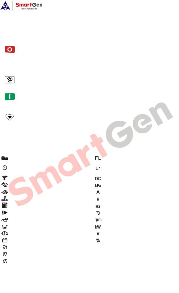
4.4. LCD ICONS |
|
|
|
|
|
|
|
|
|
|||||||
|
|
|
|
|
|
|
|
|
|
|
|
|
|
|
|
|||
|
|
Icon |
|
|
|
|
|
Definition |
|
|
Icon |
|
|
Definition |
|
|
||
|
|
|
|
|
|
|
|
|
|
|
|
|
|
|
||||
|
|
|
|
|
|
|
|
|
|
|
|
|
|
|
|
|
|
|
|
|
|
|
|
Genset start indication |
|
|
|
|
|
|
Fuel Level Indication |
|
|||||
|
|
|
|
|
|
|
|
|
|
|
|
|
|
|
||||
|
|
|
|
|
Boot |
|
time is counting(reaching crank |
|
|
|
|
Generator Voltage Indication |
|
|||||
|
|
|
|
|
disconnect condition) |
|
|
|
|
|
|
|
||||||
|
|
|
|
|
|
|
|
|
|
|
|
|
|
|||||
|
|
|
|
|
|
|
|
|
|
|
|
|
|
|||||
|
|
|
|
|
Emergency Stop Alarm |
|
|
|
|
|
|
Battery Voltage Indication |
|
|||||
|
|
|
|
|
Over Speed/Over Frequncy Alarm |
|
|
|
|
Oil Pressure Unit |
|
|||||||
|
|
|
|
|
|
|
|
|
|
|
|
|||||||
|
|
|
|
|
Under Speed/Under Frequency Alarm |
|
|
|
|
Current With Load Unit |
|
|||||||
|
|
|
|
|
|
|
|
|
|
|
|
|
|
|||||
|
|
|
|
|
High Temp. Alarm |
|
|
|
|
|
|
Hours Count |
|
|||||
|
|
|
|
|
Low Fuel Level |
|
|
|
|
|
|
Frequency Unit |
|
|||||
|
|
|
|
|
|
|
|
|
|
|
|
|
|
|||||
|
|
|
|
|
Auxiliary Alarm |
|
|
|
|
|
|
Temperature Unit |
|
|||||
|
|
|
|
|
|
|
|
|
|
|
|
|
|
|||||
|
|
|
|
|
Low Oil Pressure |
|
|
|
|
|
|
Speed Unite (revolutions per minute) |
|
|||||
|
|
|
|
|
Fail to start |
|
|
|
|
|
|
Active Power Unit |
|
|||||
|
|
|
|
|
|
|
|
|
|
|
|
|
|
|||||
|
|
|
|
|
Fail to stop |
|
|
|
|
|
|
Voltage Unit |
|
|||||
|
|
|
|
|
|
|
|
|
|
|
|
|
|
|||||
|
|
|
|
|
Voltage Abnormal |
|
|
|
|
|
|
Percentage |
|
|||||
|
|
|
|
|
Over Voltage |
|
|
|
|
|
|
|
|
|
||||
|
|
|
|
|
|
|
|
|
|
|
|
|
|
|
||||
|
|
|
|
|
Under Voltage |
|
|
|
|
|
|
|
|
|
||||
|
|
|
|
|
|
|
|
|
|
|
|
|
||||||
|
|
|
|
|
Over Current With Load |
|
|
|
|
|
|
|
||||||
HGM1790N Genset Controller |
2016-10-11 |
Version1.0 |
Page 8 of 27 |
HGM1790N GENSET CONTROLLER USER MANUAL
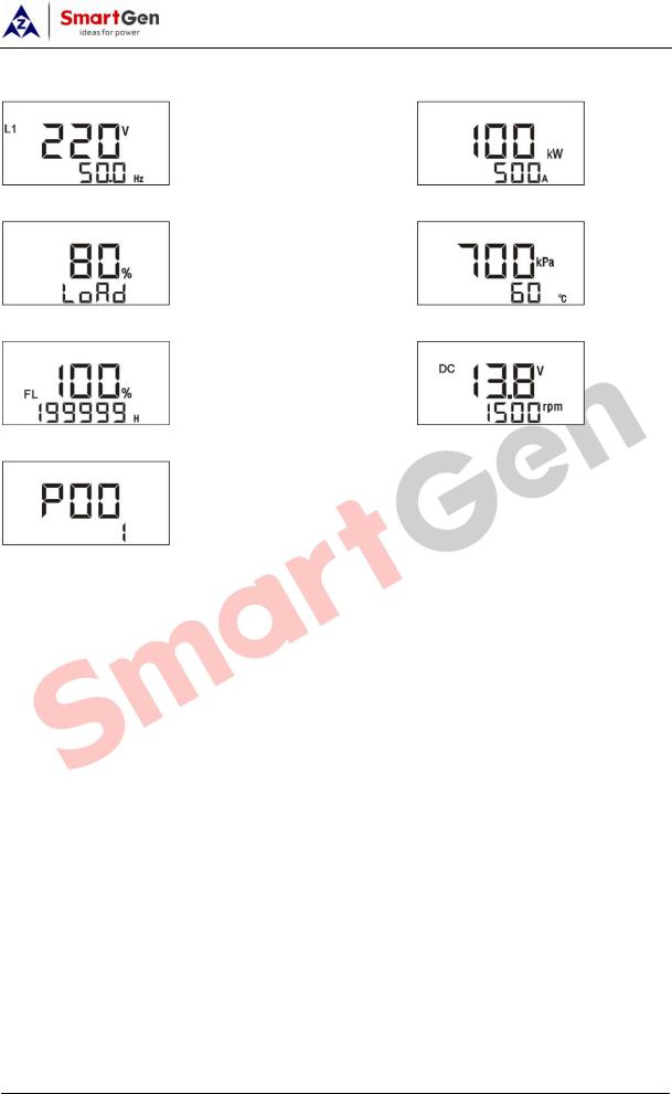
4.5. DISPLAY DESCRIPTION
Generator: phase voltage L1, frequency F |
Load: active power, current |
Load percentage |
Oil pressure, temperature |
Fuel level, total running time |
Battery voltage, generator speed |
Parameter setting
Remark:
1)When active power is “---”, which means active power is negative, please check voltage and current connection.
2)Pressure, temperature and liquid level sensors are not displayed, which means not used; when displayed “OFF” means sensors are open circuit.
3)When total running time are lower than 20000 hours, value before the decimal point is means running hours and value after the decimal point is means 1/10 hour.
HGM1790N Genset Controller |
2016-10-11 |
Version1.0 |
Page 9 of 27 |
 Loading...