

Page 1
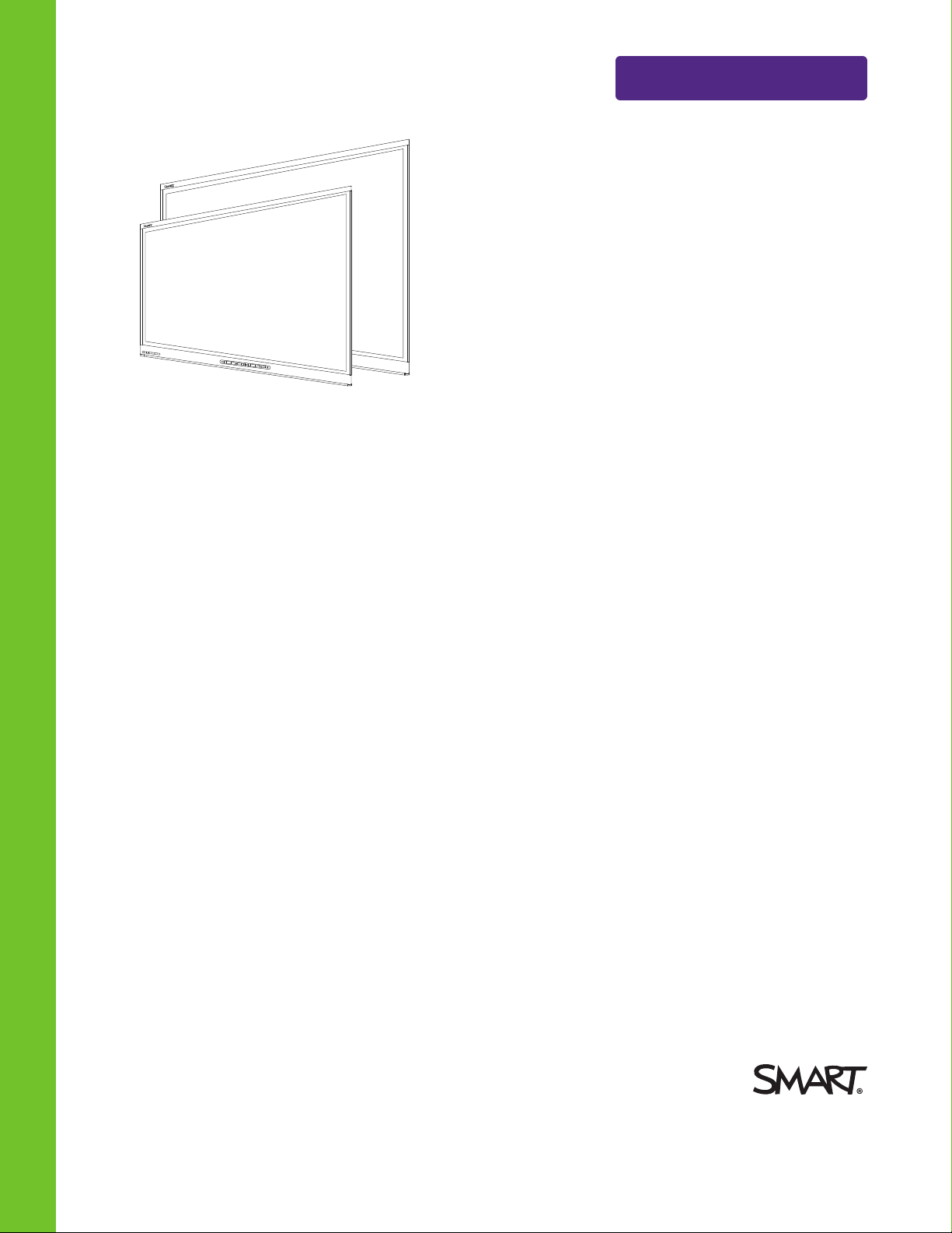
SMARTBoard® 6000 series
interactive flat panels
Help us make t hi s document better
smar ttech.com/docfeedback/170642
ADMINISTRATOR’S GUIDE
FOR MODELS SPNL-6055 AND SPNL-6065
Page 2

Product registration
If you register your SMART product, we’ll notify you of new features and software upgrades.
Register online at smarttech.com/registration.
Keep the following information available in case you need to contact SMARTSupport.
Serial number:
Date of purchase:
Licenses
The terms H DMI and HDMI Hi gh-Definition Multimedia Interface, and the H DMI log o are trademarks or regis tere d trade marks of HD MI Lice nsing LLC in the U nited
States and other co untrie s.
Trad emark no ti ce
SMARTBoard , SMARTInk, SMARTNo teboo k, DViT , smarttech, the S MART l ogo and all SMART tagli nes are trade marks o r r egi stere d trad emarks of
SMARTTe chnologie sU LC in the U.S . and/or o ther countries. All third-party pr od uct and company names may be trade marks o f their re sp ective owners.
Copyri gh t n ot ice
© 2 014–201 5SMARTTe chnologi esU LC. All rights r ese rve d. N o p art o f this p ublication may b e re pr od uced, transmitted, transcrib ed , store d i n a re trie val system
or translated into any language in any form by any means without the pr ior written co nsent o f S MARTTechnolog ie sULC. Information in this manual i s subje ct to
change without notice and d oe s not r ep re sent a co mmitment on the part o f S MART.
This p rod uct and/or use thereo f cove re d by one o r more of the foll owing U .S. patents.
www.smarttech.com/patents
01/2015
smar ttech.com/kb/170642
Page 3

Important information
WARNI NG
l Failure to follow the installation instructions shipped with your SMART product could result in
personal injury and product damage which may not be covered by your warranty.
l Do not open or disassemble the SMART product. You risk electrical shock from the high
voltage inside the casing. Opening the casing also voids your warranty.
l Do not stand (or allow children to stand) on a chair to touch the surface of your SMART
product. Rather, mount the product at the appropriate height.
l To reduce the risk of fire or electric shock, do not expose the SMART product to rain or
moisture.
l If your SMART product requires replacement parts, make sure the service technician uses
replacement parts specified by SMARTTechnologies or parts with the same characteristics
as the original.
l Ensure that any cables extending across the floor to your SMART product are properly
bundled and marked to avoid a trip hazard.
l Do not insert objects inside the cabinet ventilation holes, because they could touch
dangerous voltage points and cause electric shock, fire or product damage which may not
be covered by your warranty.
l Do not place any heavy objects on the power cable. Damage to the cable could cause
shock, fire or product damage which may not be covered by your warranty.
l Useonly extension cords and outlets into which this product’s polarized plug can be fully
inserted.
l Use the power cable provided with this product. If a power cable is not supplied with this
product, please contact your supplier. Use only power cables that match the AC voltage of
the power outlet and that comply with your country’s safety standards.
l If the glass is broken, do not touch the liquid crystal. To prevent injury, handle glass
fragments with care when disposing of them.
l Do not move or mount the interactive flat panel by connecting rope or wire to its handles.
Because the interactive flat panel is heavy, rope, wire or handle failure could lead to
personal injury.
i smar ttech.com/kb/170642
Page 4

IMP ORTAN T INFORMATI ON
l Use only VESA®-approved mounting hardware.
l Disconnect all power cables for your interactive flat panel from the wall outlet and seek
assistance from qualified service personnel when any of the following occurs:
o
The power cable or plug is damaged
o
Liquid is spilled into the interactive flat panel
o
Objects fall into the interactive flat panel
o
The interactive flat panel is dropped
o
Structural damage such as cracking occurs
o
The interactive flat panel behaves unexpectedly when you follow operating
instructions
CAUTION
l Before you clean your SMART product, shut down or disconnect the computer. Otherwise,
you may scramble the desktop icons or inadvertently activate applications when you wipe
the screen.
l Avoid setting up and using the SMART product in an area with excessive levels of dust,
humidity and smoke.
l Make sure an electrical socket is near your SMART product and remains easily accessible
during use.
l The external power supply needs to meet the Limited Power Source (LPS) requirements of
CSA/UL/IEC/EN 60950-1, when required.
l This SMART product should be used only with European TN and TT power distribution
systems.
It is not suitable for older, IT-type power distribution systems found in some European
countries. “This system (IT-type) is widely used isolated from earth, in some installations in
France, with impedance to earth, at 230/400V, and in Norway, with voltage limiter, neutral
not distributed, at 230V line-to-line.” (IEC 60950:1999)
Contact qualified personnel if you’re uncertain of the type of power system available where
you’re installing your SMART product.
l You must connect the USB cable that came with your interactive flat panel to a computer
that has a USB compliant interface and that bears the USB logo. In addition, the USB source
computer must be compliant with CSA/UL/EN 60950 and bear the CE mark and CSA and/or
UL Mark(s) for CSA/UL 60950. This is for operating safety and to avoid damage to the
interactive flat panel.
ii smar ttech.com/kb/170642
Page 5
IMP ORTAN T INFORMATI ON
IMPORTANT
l The following are the power requirements for your interactive flat panel:
Model Power requirements
SPNL-6055 90V to 240V AC, 50Hz to 60 Hz, 122 W
SPNL-6065 100V to 240V AC, 50 Hz to 60 Hz, 190 W
l For additional requirements and other information, refer to your interactive flat panel’s
specifications (see
Resources for decision makers
on page7).
iii smar ttech.com/kb/170642
Page 6

Page 7

Contents
Important information i
Chapter 1: Welcome 1
About this guide 1
About your interactive flat panel 2
About SMART software 6
Resources for administrators 6
Resources for others 7
Chapter 2: Mounting your int eractive flat panel 9
Before mounting your interactive flat panel 9
Choosing a location 10
Choosing a height 11
Chapter 3: Connecting power and devices 13
Connector panel 13
Connecting power 14
Connecting the roomcomputer 14
Connecting external speakers 15
Chapter 4: Sett ing up your interact ive flatpanel and the roomcomputer 17
Turning on your interactive flat panel and the room computer for the first time 17
Installing SMART software 18
Running the connection wizard 19
Chapter 5: Maintaining your in t eractiveflatpanel 21
Resetting your interactiveflatpanel 21
Maintaining your interactive flat panel software and firmware 22
Maintaining your interactive flat panel hardware 25
Removing and transporting your interactiveflatpanel 27
Chapter 6: Troubleshooting 29
Locating the interactive flat panel serial number 29
Resolving common issues using the indicator light 29
Resolving image issues 30
Resolving touch issues 30
Resolving connected computer issues 31
Using the SMARTConnectionWizard 32
Using SMARTBoard Diagnostics 33
v smarttech.com/kb/170642
Page 8

CONTENTS
Appendix A: Using t he on-screen display menu 35
Changing settings in the on-screen display menu 35
On-screen display menu options 36
Appendix B: Remot ely managing your interact iveflatpanel 39
Connecting and configuring a roomcontrolsystem 39
Power modes 41
Room control system programming commands and responses 41
Commands 43
Appendix C: Hardware environmental compliance 49
Waste Electrical and Electronic Equipment (WEEE) 49
More information 49
Index 51
vi smarttech.com/kb/170642
Page 9

Chapter 1
About this guide 1
About your interactive flat panel 2
Models 2
Features 2
Components 3
Screen 3
Cameras and reflective tape channel 4
Front control panel 4
Pens with erasers 5
Speakers 5
About SMART software 6
Resources for administrators 6
Training 6
Support center and knowledge base 6
Resources for others 7
Resources for decision makers 7
Resources for installers 7
Resources for users 7
This chapter introduces you to your SMARTBoard® interactive flat panel and this guide.
About this guide
This guide explains how to set up and maintain your interactive flat panel. It includes the following
information:
l How to mount your interactive flat panel
l How to connect power and devices
l How to set up your interactive flat panel
l How to maintain your interactive flat panel for years of use
l How to troubleshoot issues with your interactive flat panel
1 smar ttech.com/kb/170642
Page 10

CHAPTER 1
WEL COME
In addition, this guide includes information on your interactive flat panel’s on-screen display menu
and remote management support.
This guide is intended for individuals who are responsible for installing and maintaining interactive
flat panels in their organizations. Other documentation and resources are available for individuals
who use interactive flat panels.
About your interactive flat panel
Your SMARTBoard® interactive flat panel features SMART’s proprietary DViT®
(DigitalVisionTouch) technology on an LCD screen with e-LED backlight.
Models
The SMARTBoard 6000 series interactive flat panels consists of two models:
l SMARTBoard 6055 interactive flat panel
l SMARTBoard 6065 interactive flat panel
Differences between these models are noted in this guide.
Features
Your interactive flat panel includes the following features:
Feature Description
Touch support You can do everything on your interactive flat panel that you can
do at your computer—open and close applications, meet with
others, create new documents or edit existing ones, visit websites,
play and manipulate videos, and so on—by touching the interactive
flat panel’s surface.
You can use an array of gestures within applications, including
panning, scaling, rotating and zooming in and out.
The interactive flat panel’s support for at least four simultaneous
touches enables you and other users to interact with objects on the
screen at the same time.
Writing and drawing
support
You can write over any application in digital ink using one of the
supplied pens, and then erase the digital ink using the eraser on the
pen or your palm.
You and another writer can write or draw digital ink on the screen at
the same time. The Pen ID feature enables you to assign different
ink appearances to each pen.
Audio support Your interactive flat panel includes integrated speakers for
presenting audio from connected input sources.
2 smar ttech.com/kb/170642
Page 11
CHAPTER 1
WEL COME
Components
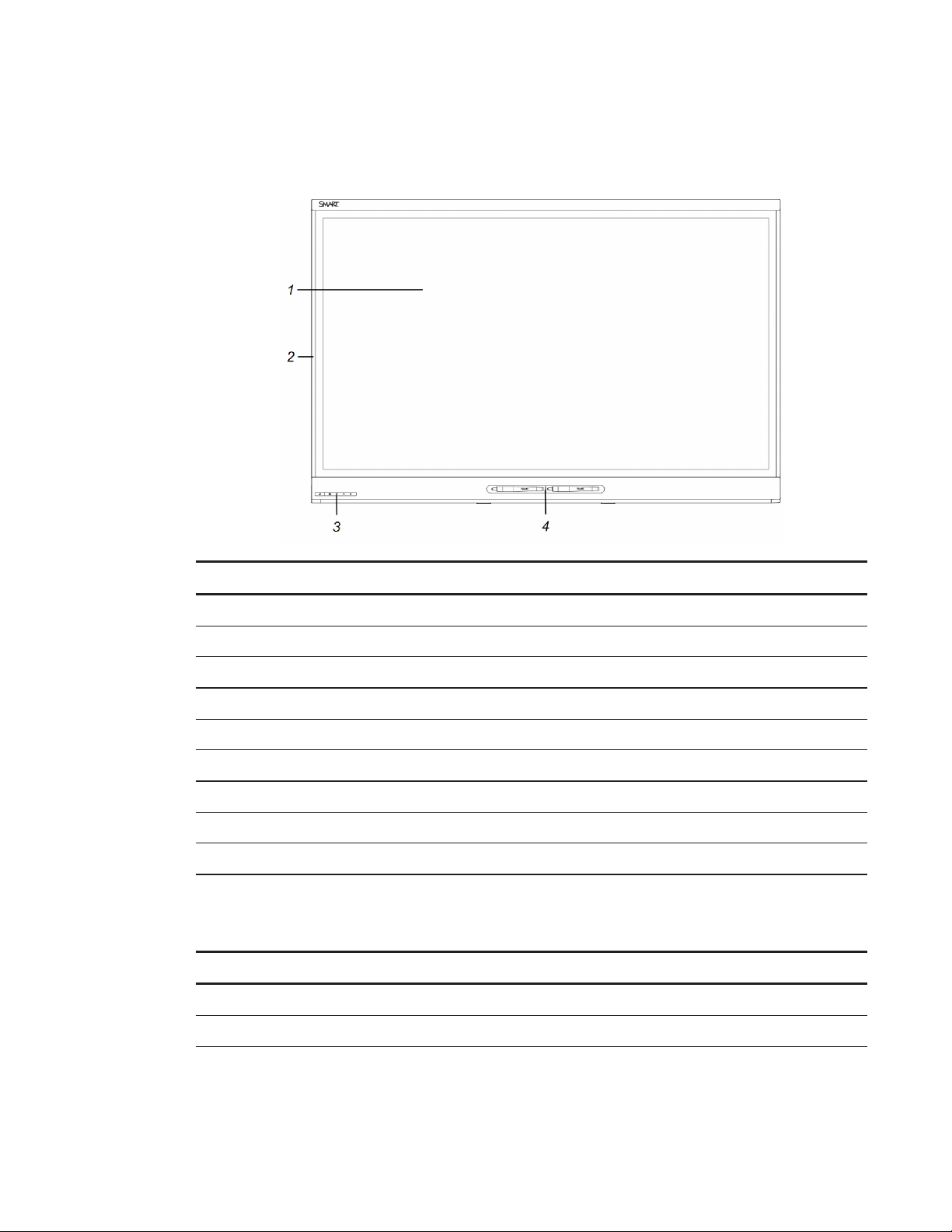
Your interactive flat panel consists of the following components:
No. Name More informat ion
Pict ured
1 Screen Page3
2 Cameras and reflective tape channel Page4
3 Front control panel Page4
4 Pen with eraser (×2) Page5
Not pict ured
5 Speakers Page5
6 Connector panel Page13
7 Menu control panel Page35
Screen
The screen specifications vary by model:
Models Diagonal Widt h Height Aspect rat io
SPNL-6055 54 1/2" (138.4 cm) 47 5/8" (121 cm) 26 3/4" (68 cm) 16:9
SPNL-6065 64 1/2" (163.9 cm) 56 1/4" (142.8 cm) 31 5/8" (80.4 cm) 16:9
For information on cleaning the screen, see
3 smarttech.com/kb/170642
Cleaning the screen
on page25.
Page 12
CHAPTER 1
WEL COME
Cameras and reflective tape channel
In the corners of the screen, there are cameras that track finger and pen positions across the
screen. The screen is bordered by a channel that contains reflective tape.
For information on cleaning the camera windows and reflective tape, see
Cleaning the screen
page25.
CAUTION
l Keep the reflective tape dry.
l Do not remove or damage the reflective tape.
IMPORTANT
l Do not attach items such as adhesive notes to the screen because they will interfere with
the cameras.
l Do not place anything in the channel because it will interfere with the cameras.
Front cont rol panel
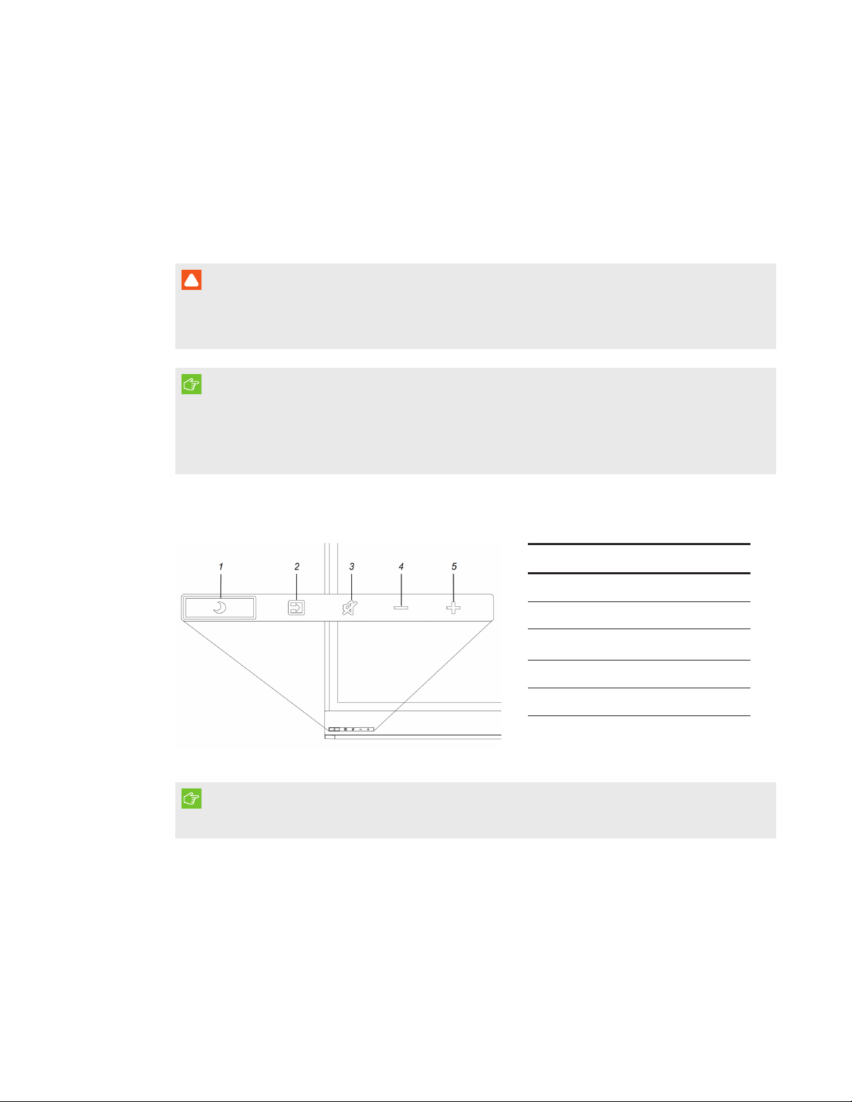
The front control panel contains the Standby, Input Select, Mute and volume control buttons.
No. Name
1 Standby button
2 Input Select button
on
3
Mute button
4 Volume decrease
5 Volume increase
IMPORTANT
If there is a film over the front control panel, remove the film before using the front control panel.
In normal operation, all buttons are white.
4 smarttech.com/kb/170642
Page 13
CHAPTER 1
WEL COME
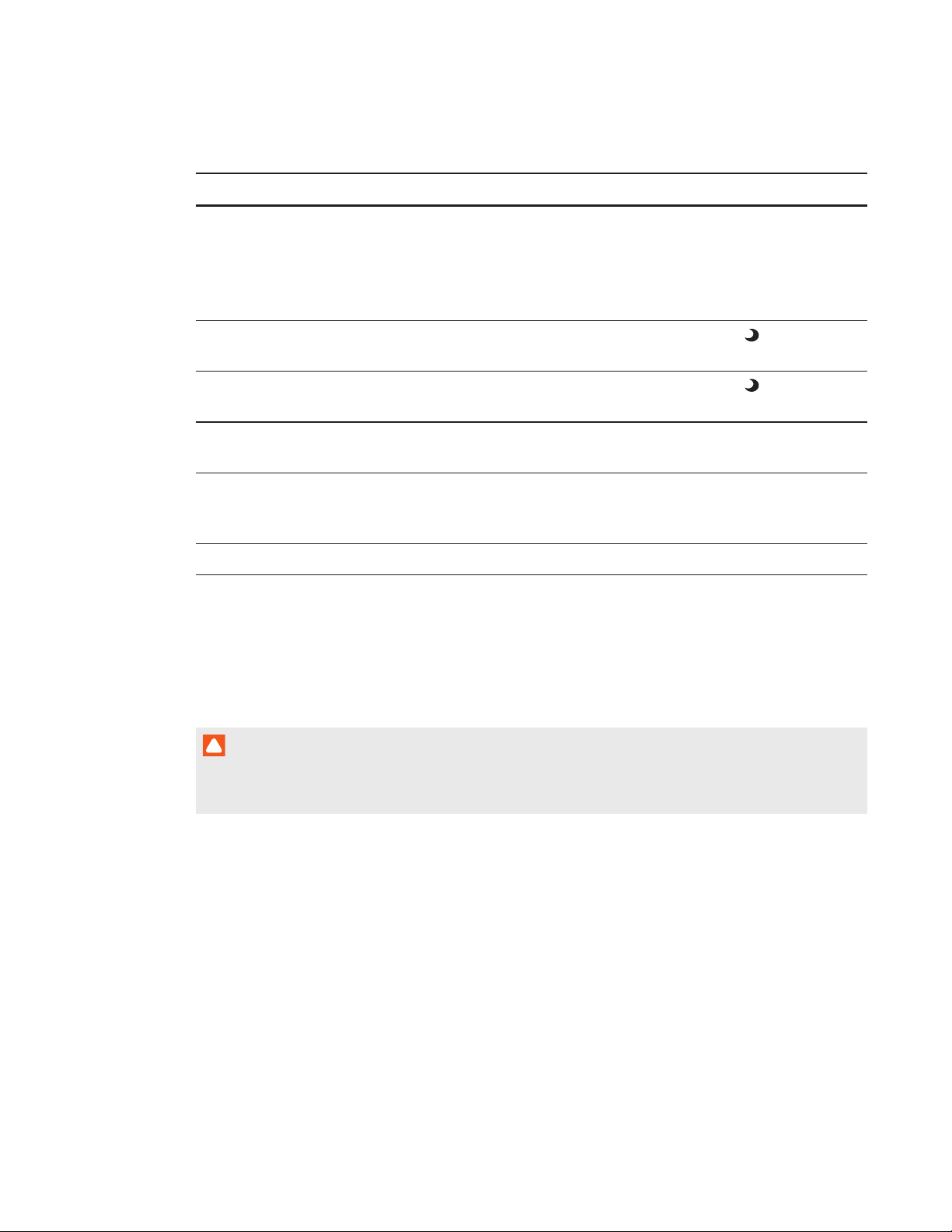
The Standby button also functions as an indicator light:
Indicator light Interact ive flat panel status Troubleshooting
Off Not receiving power Confirm the interactive flat panel’s power
cable is connected to the power outlet
(see page14).
Flick the power switch to the ON (I)
position (see page17).
Solid amber DPMS (power management)
mode
Slowly flashing
Standby mode Press the Standby button to exit
amber
Flashing amber No USB connection from the
Press the Standby button to exit
DPMSmode.
Standby mode.
Verify your connections (see page14).
connected computer
Slowly flashing
white
SMARTBoard service not
running on the connected
computer
Ensure that SMARTProductDrivers is
installed and that the SMARTBoard
service is running.
Solid white Normal operation [N/A]
Pens with erasers
Your interactive flat panel comes with two pens with erasers attached.
The bottom bezel of the interactive flat panel includes magnetic holders for the pens. Removing a
pen from the holders activates it and enables you to either draw or erase digital ink.
CAUTION
When returning the pen to the magnetic holder, ensure that it is centered in its holder to prevent
it from falling and potentially being damaged.
Speakers
Your interactive flat panel includes two 10 W integrated side firing speakers.
You can connect external speakers if desired (see
5 smar ttech.com/kb/170642
Connecting external speakers
on page15).
Page 14

CHAPTER 1
WEL COME
About SMART software
You can install the following SMART software on the computers connected to your interactive flat
panel to take full advantage of the interactive flat panel’s features:
Soft ware Description
SMARTProductDrivers SMARTProductDrivers enables connected computers to detect
input from your interactive flat panel.
SMARTInk™ SMARTInk enables you to write and draw in digital ink over open
applications, files, folders, websites and any other open window on
your computer. When you write outside the open windows on your
computer, a SMARTInk Note appears and you can write inside the
note.
When you open an application that has its own ink tools, you can
turn off SMARTInk, and then use the application’s ink tools to write
in the content.
SMARTNotebook®
collaborative learning
software
SMARTNotebook software enables you to use your interactive flat
panel in a classroom.
Resources for administrators
In addition to this guide, there are other resources for administrators.
Training
The SMART training website (smarttech.com/training) includes an extensive library of training
resources you can refer to when learning how to set up and maintain your interactive flat panel.
Support center and knowledge base
The Support center (smarttech.com/support) contains a library of documents, including this guide,
and a knowledge base that you can search when troubleshooting issues.
6 smar ttech.com/kb/170642
Page 15

CHAPTER 1
WEL COME
Resources for others
SMART provides resources for decision makers, installers and users as well as administrators.
Resources for decision makers
Decision makers can refer to the specifications for detailed information on the interactive flat
panels.
Int eractive flat panel Specifications
SMARTBoard 6055 interactive flat panel smarttech.com/kb/170817
SMARTBoard 6065 interactive flat panel smarttech.com/kb/170640
Resources for installers
Installers can refer to the installation instructions included with your interactive flat panel when
installing the product. If installers have misplaced these installation instructions, they can download
a PDF version from smarttech.com/kb/170641.
Resources for users
Users can refer to the SMARTNotebook software Help for information on using the software with
the interactive flat panel. To open the Help, users can select Help > Cont ents in the
SMARTNotebook software window.
7 sm arttech.com/kb/170642
Page 16

Page 17
Chapter 2
Before mounting your interactive flat panel 9
Choosing a location 10
Choosing a height 11
To mount your interactive flat panel on a wall, you require a team of professional installers.
This chapter is intended for installers. Installers should read this chapter along with the installation
instructions included with the interactive flat panel before they mount the interactive flat panel.
WARNI NG
Improper mounting of your interactive flat panel can result in personal injury and product
damage.
Before mounting your interactive flat panel
Do the following before mounting your interactive flat panel:
l Review the environmental requirements in the interactive flat panel’s specifications (see
Resources for decision makers
l Save all product packaging so that it’s available if you need to transport the interactive flat
panel. If the original packaging isn’t available, you can purchase new product packaging from
your authorized SMART reseller (smarttech.com/where).
l Refer to local building codes to ensure the wall can support the weight of the interactive flat
panel specified in the following table and mounting equipment.
Model Weight
SPNL-6055 104 lb. (47.4 kg)
SPNL-6065 135 lb. 6 oz. (61.4 kg)
l Use a standard VESA 400 mm × 400 mm mounting plate (not included) to mount the
interactive flat panel on a wall.
on page7).
9 smar ttech.com/kb/170642
Page 18
CHAPTER 2
MOUN TING YOUR INTERACTIVE FLATP ANEL
l Use M8 screws to fasten the wall bracket.
Screw length 20 mm + x mm < M8 < 45 mm + xmm
where x is the total thickness of the wall bracket and washer
Fasten force
97.36–177.01 in-lb. (11–20 N·m)
CAUTION
Do not over-tighten the screws.
NOTE
SMART recommends M8 × 30 mm mounting screws for standard installations where the
total wall mount bracket and washer thickness is less than 7 mm.
l Because the receptacles might not be easily accessible after the installers mount the
interactive flat panel, consider connecting cables for power, computers and other devices
while the interactive flat panel is still in its packaging (see
Connecting power and devices
page13).
l Before turning on the interactive flat panel for the first time, clean the camera windows and
reflective tape following the instructions in
Cleaning the camera windows a nd reflective tape
on page26.
Choosing a location
Do the following when choosing a location for the interactive flat panel:
on
l Do not install the interactive flat panel in a location where a door or gate could hit it.
l Do not install the interactive flat panel in an area where it will be subjected to strong vibrations
or dust.
l Choose a location that’s far from bright light sources, such as windows and strong overhead
lighting. IR lighting can cause issues with the performance of the cameras and can lead to
unintentional or missed touches.
l Do not install the interactive flat panel near where the main power supply enters the building.
l Ensure adequate ventilation or provide air conditioning around the interactive flat panel so
that heat can flow away from the unit and the mounting equipment.
l If you mount the interactive flat panel in a recessed area, leave at least 4" (10 cm) of space
between the interactive flat panel and the recessed walls to enable ventilation and cooling.
10 smarttech.com/kb/170642
Page 19
CHAPTER 2
MOUN TING YOUR INTERACTIVE FLATP ANEL
Choosing a height
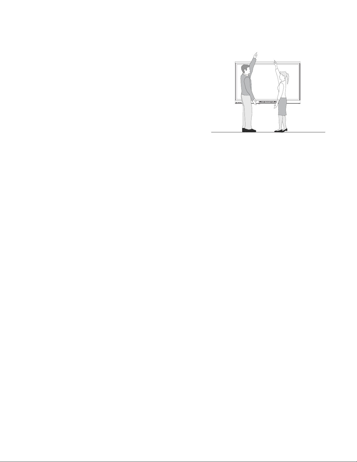
Consider the general height of the user community
when you choose the height for the interactive flat
panel.
11 smar ttech.com/kb/170642
Page 20

Page 21
Chapter 3
Connector panel 13
Connecting power 14
Connecting the roomcomputer 14
Connecting external speakers 15
This chapter includes information on connecting your interactive flat panel to power, computers
and other devices.
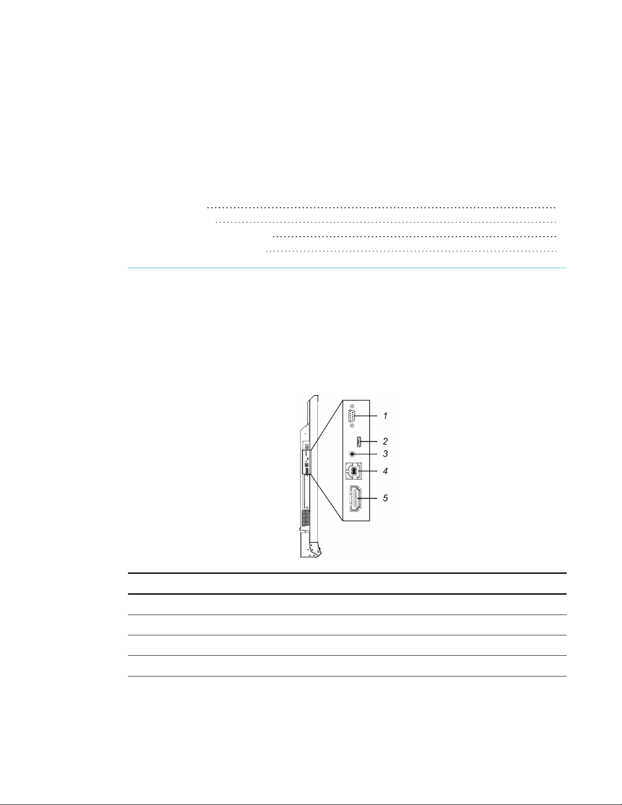
Connector panel
The following diagram and table present the connectors on the interactive flat panel:
No. Connect or Connect s t o Notes (if any)
1 RS-232 Room control system See page39.
2 USB Micro-B [N/A] This connector is a service port.
3 Stereo 3.5 mm External speakers See page15.
4 USB Type-B Room computer (data) See page14.
13 smar ttech.com/kb/170642
Page 22
CHAPTER 3
CONNECTING P OWER AND DEVICES
No. Connect or Connect s t o Notes (if any)
5 HDMI® Room computer (video) The HDMI cable should be HDMI 1.4
compliant and no longer than 16'5"
(5m).
For more information, see below.
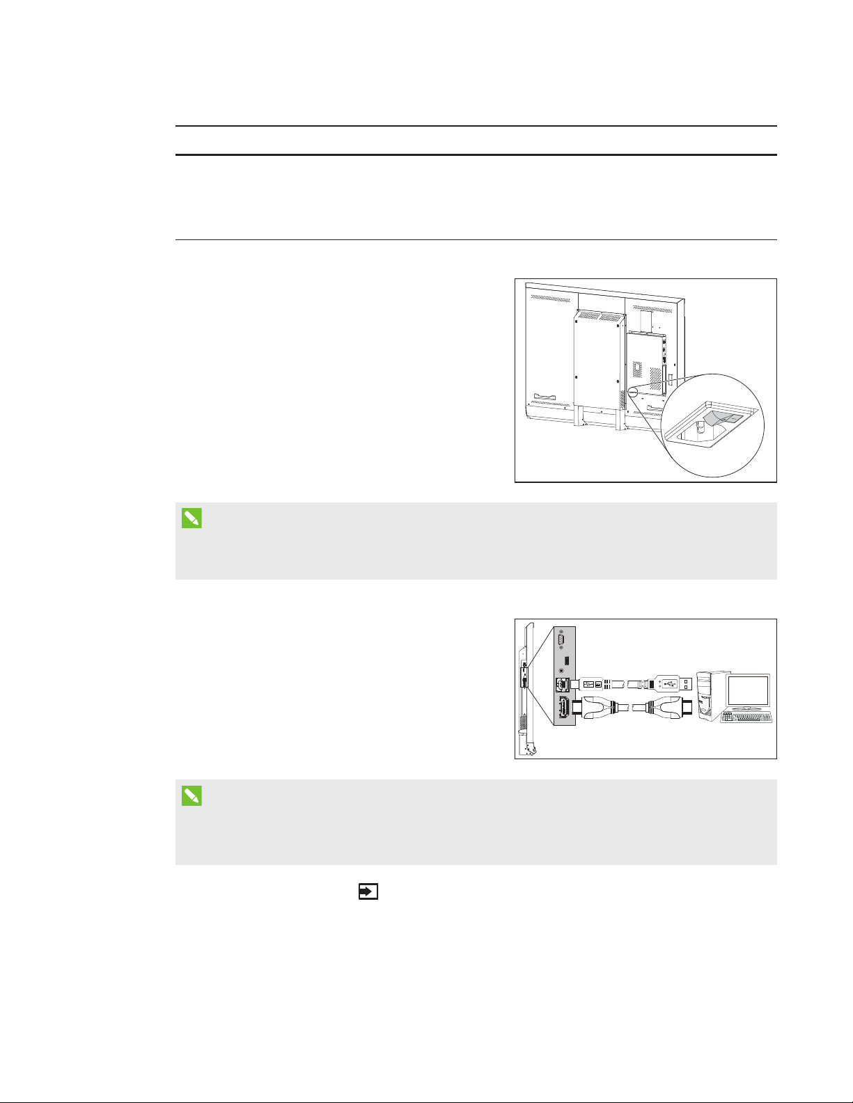
Connecting power
Connect the supplied power cable from the AC
power inlet on the bottom of the interactive flat panel
to a power outlet.
NOTE
Refer to your interactive flat panel’s specifications for power requirements and power
consumption information (see
Resources for decision makers
on page7).
Connecting the
roomcomputer
Using USB and HDMI cables, connect the room
computer to the appropriate connectors on the
interactive flat panel.
NOTES
l You can use the interactive flat panel with up to two USB-XT extenders.
l If you use a CAT 5 USB extender, the maximum length of the Cat 5 cable is 52' (16 m).
Press the Input Select button on the front control panel until the input source is HDMI.
14 smar ttech.com/kb/170642
Page 23
CHAPTER 3
CONNECTING P OWER AND DEVICES
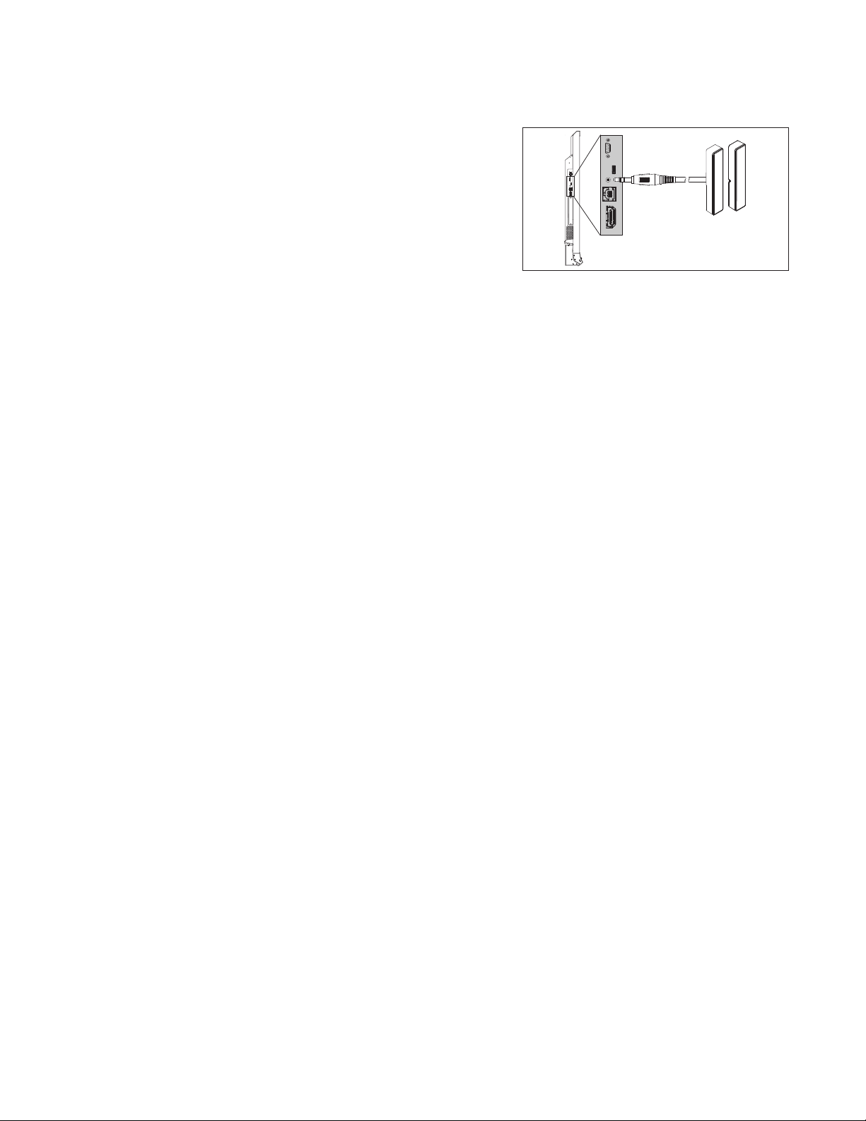
Connecting external speakers
Your interactive flat panel includes two 10 W
speakers. However, you can connect external active
speakers using the stereo 3.5 mm connector.
15 smarttech.com/kb/170642
Page 24

Page 25
Chapter 4
and the roomcomputer
Turning on your interactive flat panel and the room computer for the first time 17
Installing SMART software 18
Running the connection wizard 19
This chapter explains how to set up your interactive flat panel and the room computer after
mounting your interactive flat panel and connecting power and devices.
Turning on your interactive flat panel and the room computer for the first time
After connecting the room computer to the interactive flat panel (see
roomcomputer
flatpanel
on page14) and mounting the interactive flat panel (see
on page9), you can turn on both devices.
Connecting the
Mounting your interactive
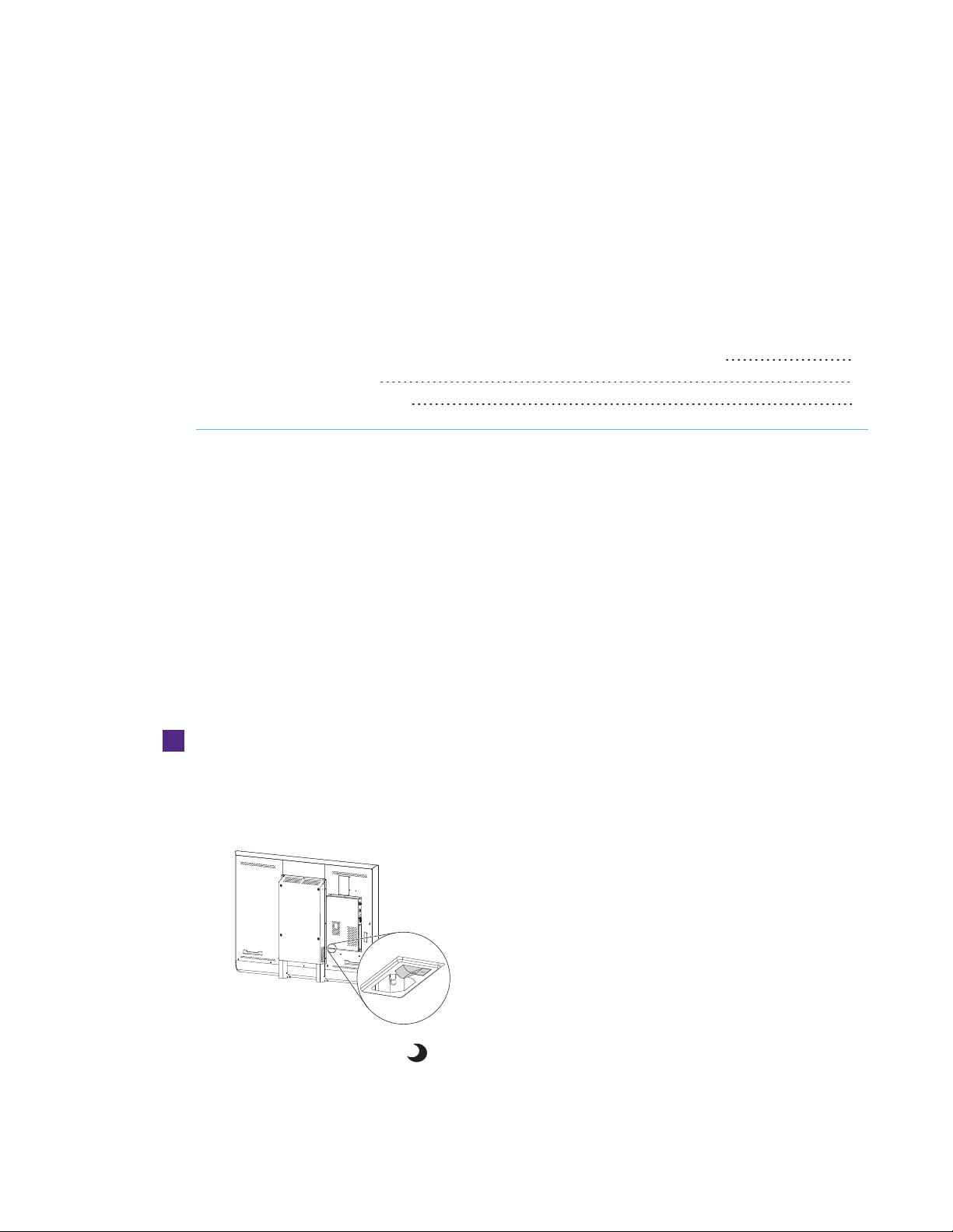
To t u rn on your int eractive flat panel and t he room computer for t h e first t ime
1. Turn on the room computer.
2. Turn on your interactive flat panel by flicking the power switch beside the AC power inlet to
the ON (I) position.
Press the Standby button on the front control panel.
3.
17 sma rttech.com/kb/170642
Page 26

CHAPTER 4
SETTING U P YOUR IN TERACTIVE FL ATP ANEL AND THE R OOMCOMP UTER
Installing SMART software
To take full advantage of your interactive flat panel’s features, you must download and install
SMART software on the room computer.
The purchase of your interactive flat panel includes a license for SMARTNotebook software and a
one-year subscription to the SMARTNotebook Advantage software maintenance plan. See
smarttech.com/notebook for more information.
TIP
You can also install SMARTNotebook software from the DVD included with your interactive flat
panel.
To download and install SMAR T soft ware
1. Go to smarttech.com/downloads.
2. Scroll to the
3. Click Choose a version, and then select the most recent version.
4. Click Download.
5. Follow the on-screen instructions to save the installer to a temporary location.
6. Double-click the installer.
7. Follow the on-screen instructions to install SMART software.
SMARTNotebook software
section.
18 smarttech.com/kb/170642
Page 27

CHAPTER 4
SETTING U P YOUR IN TERACTIVE FL ATP ANEL AND THE R OOMCOMP UTER
Running the connection wizard
After turning on your interactive flat panel and the room computer for the first time and installing
SMART software, run the connection wizard to orient the interactive flat panel.
To run t he connection wizard
1. Access the SMARTConnection Wizard by opening SMARTSettings (see
OpeningSMARTSettings
2. Press Con nection Wizard.
The
SMART Connection Wizard
3. Select the interactive flat panel from the list of connected SMART interactive products, and
then press Next .
4. Select Product is being set up for the first time, and then press Next.
5. Follow the on-screen instructions to orient the interactive flat panel for the firsttime.
on page22).
appears.
19 smarttech.com/kb/170642
Page 28

Page 29

Chapter 5
interactiveflatpanel
Resetting your interactiveflatpanel 21
Maintaining your interactive flat panel software and firmware 22
OpeningSMARTSettings 22
Updating firmware 22
Updating software 23
Orienting your interactive flat panel 23
Calibrating your interactive flat panel 24
Maintaining your interactive flat panel hardware 25
Checking the interactive flat panel installation 25
Cleaning the screen 25
Cleaning the camera windows and reflective tape 26
Maintaining ventilation 26
Preventing condensation 27
Maintaining pens 27
Removing and transporting your interactiveflatpanel 27
Removing your interactive flat panel 27
Transporting your interactive flat panel 28
This chapter includes common maintenance procedures for your interactive flat panel.
Resetting your interactiveflatpanel
You can reset your interactive flat panel using the front control panel.
To reset your interact ive flat panel
Press the Standby button on the front control panel.
1.
A message appears on the screen, prompting you to either press the button again to enter
Standby mode or press and hold the button to reset the interactive flat panel.
21 smarttech.com/kb/170642
Page 30

CHAPTER 5
MAIN TAINING YOUR INTERACTIVEFLATPANEL
Press and hold the St andby button until the screen turns black.
2.
The interactive flat panel resets and then your computer’s logon screen or desktop appears
on your interactive flat panel.
Maintaining your interactive flat panel software and firmware
This section includes common maintenance procedures for your interactive flat panel software and
firmware.
OpeningSMARTSettings
Several maintenance and troubleshooting procedures in this guide require you to open
SMARTSettings.
To open SMARTSettings on Windows 7 operating syst em
Select St art > All Programs > SMART Technologies > SMART Tools > SMART Sett ings.
SMARTSettings appears.
To open SMARTSettings on Windows 8 operat ing syst em
1. Open the
2. Press SMARTSett ings.
SMARTSettings appears.
To open SMARTSettings on MacOS operat ing system software
Press the SMAR TBoard icon on the Mac menu bar.
1.
2. Press SMARTSett ings.
SMARTSettings appears.
Apps
screen.
Updating firmware
Your interactive flat panel uses firmware on its processor. You can update the firmware. For more
information, see
(knowledgebase.force.com/?q=000015055).
Updating the firmware on your SMARTBoard 6065 interactive flat panel
22 sma rttech.com/kb/170642
Page 31
CHAPTER 5
MAIN TAINING YOUR INTERACTIVEFLATPANEL
Updating software
SMARTProductUpdate (SPU) is included in the SMART software you installed to use your
interactive flat panel (see
updates to the SMART software posted on the SMART website. You can configure SPU to prompt
users to install updates or to install updates automatically.
NOTE
If you didn’t install SPU, you can download updates to SMART software from
smarttech.com/downloads.
Installing SMART software
on page18). SPU periodically checks for
Orienting your interactive flat panel
If the location of your touch is misinterpreted (the pointer appears a distance from the actual
contact), orient your interactive flat panel.
NOTE
You can use your finger or an interactive flat panel pen to orient your interactive flat panel.
To orient the int eractive flat panel
1. Open SMARTSettings (see
2. Press Orient.
3. Press the red targets as they appear. Hold your finger or the tip of the pen at the center of
each target, and then lift the pen or finger. When you lift the pen or finger, the target moves to
the next orientation point.
IMPORTANT
Hold the pen perpendicular to the screen.
4. Continue until you’ve pressed all the targets.
The orientation window closes.
5. If this doesn’t correct inaccurate touch, calibrate your interactive flat panel (see
your interactive fla t panel
OpeningSMARTSettings
on the next page).
on the previous page).
Calibrating
23 sm arttech.com/kb/170642
Page 32

CHAPTER 5
MAIN TAINING YOUR INTERACTIVEFLATPANEL
Calibrating your interactive flat panel
Digital cameras in the corners of the interactive flat panel track the position of the pens, eraser and
your finger on the interactive surface, and then send the information to the SMART software, which
interprets this information as mouse clicks, digital ink or ink removal in the appropriate location.
Calibration determines the position and angles of the cameras to accurately identify the location of
touches on your interactive flat panel.
IMPORTANT
If an error message appears while you are calibrating your interactive flat panel, contact
SMARTSupport (smarttech.com/contactsupport).
To calibrate your interact ive flat panel
1. Open SMARTSettings (see
OpeningSMARTSettings
on page22).
2. Press SMART Hardware Sett ings.
3. If you have more than one SMART product connected, select the interactive flat panel.
4. Select Advanced Settings from the drop-down list.
5. Press Calibrate.
The calibration screen appears. This can take a few moments.
6. Press the red target with the tip of an interactive flat panel pen. Hold the tip at the center of
the target until the target turns green, and then lift the pen.
The target moves to the next location.
NOTE
You can calibrate a target again by pressing the LEFT ARROW key on your keyboard.
7. Continue pressing targets until the second calibration screen and a grid appears.
An example appears briefly to demonstrate how to draw across the screen to calibrate the
interactive surface.
8. Use a pen to draw a spiral horizontally across the grid. As you draw, the ink is blue. As you
complete each square, the square becomes green.
9. When all the squares are green, a progress bar appears.
When the progress bar is full, the interactive flat panel displays the message
Calibrationsuccessful
10. Orient your interactive flat panel (see
.
Orienting your interactive flat pa nel
page).
24 smarttech.com/kb/170642
on the previous
Page 33

CHAPTER 5
MAIN TAINING YOUR INTERACTIVEFLATPANEL
Maintaining your interactive flat panel hardware
If you properly maintain your interactive flat panel hardware, it will provide years of use.
Checking the interactive flat panel installation
Inspect your interactive flat panel installation frequently to ensure that it remains securely installed.
l Check the mounting location for signs of damage or weakness that can occur over time.
l Check for loose screws, gaps, distortions or other issues that could occur with the mounting
apparatus.
If you find an issue, contact a professional installer.
Cleaning the screen
Follow these instructions to clean the interactive flat panel screen without damaging its anti-glare
coating or other product components.
CAUTION
l Do not use permanent or dry-erase markers on the screen. If dry-erase markers are used on
the screen, remove the ink as soon as possible with a lint-free, non-abrasive cloth.
l Do not rub the screen with a dense or rough material.
l Do not apply pressure to the screen.
l Do not use cleaning solution or glass cleaner on the interactive flat panel screen, because
they can deteriorate or discolor the screen.
l Avoid touching the reflective tape between the screen and the bezel, and ensure that this
strip stays dry. Damage to this strip affects touch interactivity.
To clean the screen
1. Turn off the room computer.
Press the Standby button on the front control panel twice.
2.
3. Flick the power switch beside the AC power inlet.
4. Wipe the screen with a lint-free, non-abrasive cloth.
25 sma rttech.com/kb/170642
Page 34

CHAPTER 5
MAIN TAINING YOUR INTERACTIVEFLATPANEL
Cleaning the camera windows and reflective tape
The DViT technology in your interactive flat panel uses four cameras in the corners of the frame
and the reflective material between the screen and the bezels. Excessive dust buildup on the
camera windows or reflective tape can impair touch performance.
These areas should be inspected regularly for dust and should be cleaned if any obvious dust
buildup has occurred.
CAUTION
l Do not use compressed air to clean the camera windows or borders.
l Do not use water, chemicals or cleaning agents.
l Applying too much pressure when cleaning the tape or cameras can damage the tape and
cause performance issues or errors.
To clean the camera windows and reflective tape
1. With a clean lint-free cloth, gently wipe the camera windows in the top corners and the
reflective tape along the top of your interactive flat panel screen using the cloth.
2. Gently wipe the reflective tape along the sides of your interactive flat panel screen.
3. Gently wipe the camera windows in the bottom corners and the reflective strip across the
bottom of your interactive flat panel screen.
Maintaining ventilation
Your interactive flat panel requires ventilation to function. Dust buildup in the ventilation holes
compromises cooling and leads to product failure.
l Clean accessible ventilation holes monthly with a dry cloth.
l Use a vacuum cleaner with a narrow hose end fitting to clear the back ventilation holes
regularly. You might have to remove the interactive flat panel from your wall. For more
information on removing your interactive flat panel see
on the next page.
CAUTION
Removing your interactive flat pa nel
Avoid setting up or using your interactive flat panel in an area with excessive levels of dust,
humidity or smoke.
26 sma rttech.com/kb/170642
Page 35

CHAPTER 5
MAIN TAINING YOUR INTERACTIVEFLATPANEL
Preventing condensation
Your interactive flat panel screen contains layers of glass that can collect condensation, especially
in the following conditions:
l Temperature extremes with high humidity
l Rapid changes in humidity, which can occur when you operate the product near water, such as
a pool, kettle or air conditioner ventilator
l Direct exposure to sunlight
To evaporate condensation from your interact ive flat panel
1. Remove the humidity source from the interactive flat panel, if possible.
2. Turn off the interactive flat panel.
3. Remove any moisture from the interactive flat panel with a smooth, dry cloth.
4. Leave the interactive flat panel turned off for 48 hours.
Maintaining pens
To prevent damage to your interactive flat panels’ anti-glare coating, replace a pen if its nib
becomes worn. You can purchase replacement pens from the Store for SMARTParts
(seesmarttech.com/Support/PartsStore).
Removing and transporting your
interactiveflatpanel
On occasion, you might need to remove your interactive flat panel from its current location and
transport it to another location.
Removing your interactive flat panel
To safely remove your interactive flat panel, use two or more professional installers.
WARNI NG
l Do not attempt to move the interactive flat panel using your own strength. The interactive
flat panel is very heavy.
l Do not move the interactive flat panel by connecting a rope or wire to the handles on the
back. The interactive flat panel can fall and cause personal injury and product damage.
27 smar ttech.com/kb/170642
Page 36
CHAPTER 5
MAIN TAINING YOUR INTERACTIVEFLATPANEL
IMPORTANT
Follow the instructions included with the floor stand or mounting apparatus.
To remove your interact ive flat panel
1. Turn off the room computer.
Press the Standby button on the front control panel twice.
2.
3. Flick the power switch beside the AC power inlet.
4. Remove all accessible cables and connectors.
5. Lift your interactive flat panel from its mounting location.
WARNI NG
Do not place the interactive flat panel on a sloping or unstable cart, stand or table, because
the interactive flat panel could fall, resulting in injury and severe product damage.
CAUTION
Do not leave the interactive flat panel face up, face down or upside down for an extended
period of time, because it could cause permanent damage to the screen.
6. Remove the mounting brackets.
Transporting your interactive flat panel
Save your original packaging so that you can repack your interactive flat panel with as much of the
original packaging as possible. This packaging was designed with optimal shock and vibration
protection. If your original packaging isn’t available, you can purchase the same packaging directly
from your authorized SMART reseller (smarttech.com/where).
CAUTION
Transport your interactive flat panel only in original or replaced packaging. Transporting your
interactive flat panel without correct packaging voids your warranty and could lead to product
damage.
28 smarttech.com/kb/170642
Page 37

Chapter 6
Locating the interactive flat panel serial number 29
Resolving common issues using the indicator light 29
Resolving image issues 30
Resolving touch issues 30
Resolving connected computer issues 31
Using the SMARTConnectionWizard 32
Using SMARTBoard Diagnostics 33
This chapter provides you with the information necessary to solve simple issues that can occur with
your interactive flat panel. If issues persist, or aren’t covered in this chapter, contact
SMARTSupport (smarttech.com/contactsupport).
Locating the interactive flat panel serial number
When you contact SMARTSupport, you might be asked to provide the interactive flat panel
serialnumber. The serial number is located in two places:
l The on-screen display menu (see
l Underneath the bottom bezel
Serial Number
on page38)
Resolving common issues using the indicator light
The Standby button on the front control panel also functions as an indicator light. You can use the
indicator light to resolve common issues with the interactive flat panel. For more information, see
Front control panel
29 sma rttech.com/kb/170642
on page4.
Page 38
CHAPTER 6
TROUBLESHOOTING
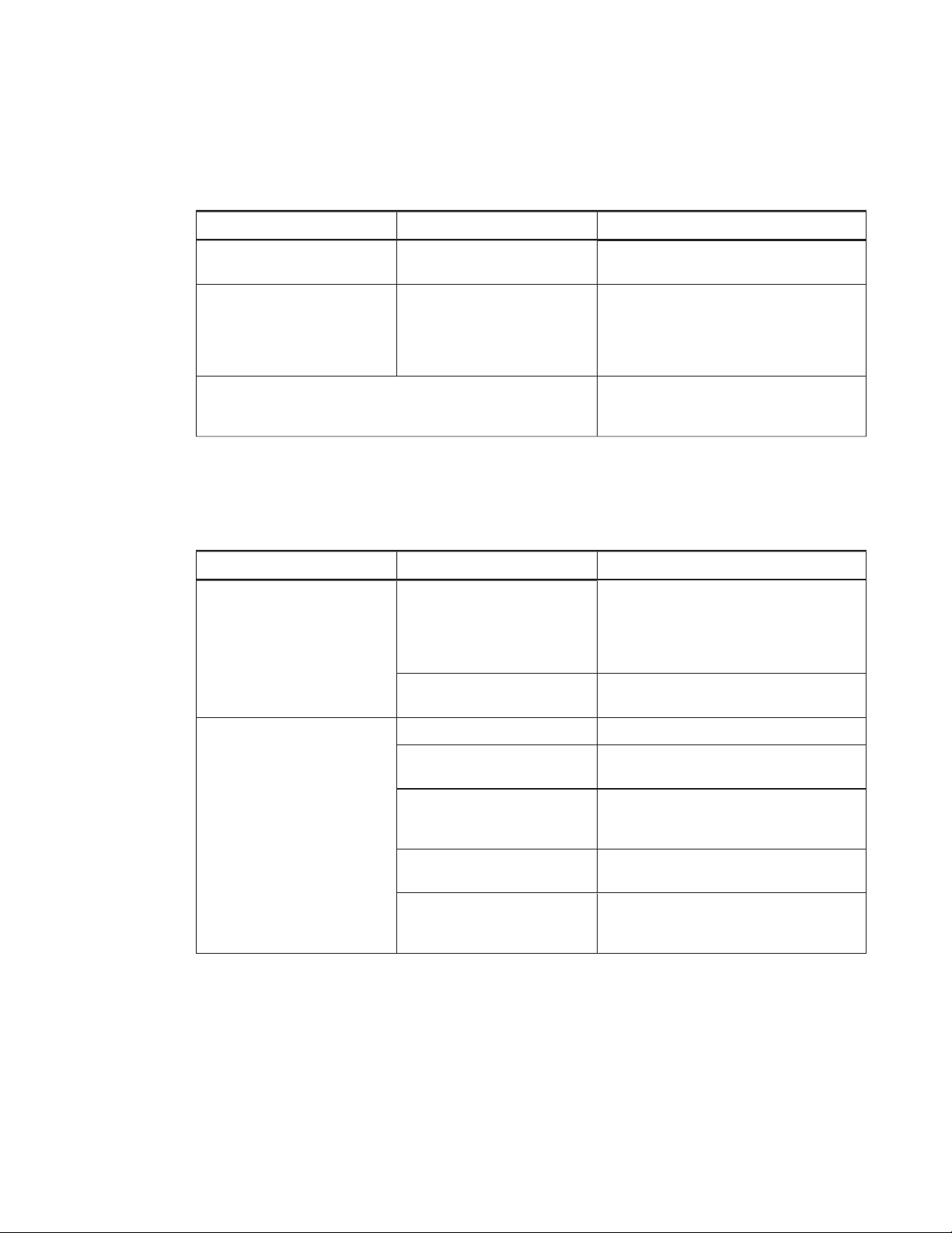
Resolving image issues
Use the following table to resolve image issues:
Symptom Cause Solut ion
The image is too light, too dark or
has poor ima ge quality.
There is a persistent image on the
screen.
There are other ima ge issues. Return all on-screen display menu
Your interactive flat panel’s picture
settings might be set incorrectly.
An image was displayed for too
long.
Adjust the Picture options (see
page36).
l Turn off your interactive flat panel and
leave it turned off for as long as the image
was on the screen.
l Set up screen savers on any connected
computers to prevent persistent images.
settings to their default values (see
page38).
Resolving touch issues
Use the following table to resolve touch issues:
Symptom Cause Solut ion
When you touch the screen, the
pointer a ppears in the wr ong
location.
You ar en’t touching the screen at a
right angle.
Your interactive flat panel isn’t
oriented.
For more information,see
drawing on your SMART Board interactive
whiteboard is inaccurate
(knowledgebase.force.com/
?q=000013976).
Orient your interactive flat panel (see
page23.)
Touching and
Picture
on
An area of the screen doesn’t
respond to your touch or when you
draw digital ink, the lines are
broken.
30 smarttech.com/kb/170642
Something is blocking the camer as. Ensure nothing is taped to the screen.
Something is on the reflective tape
channel.
Your finger or pen is skipping as
you draw. This is most common on
the upstroke.
Bright lights are interfering with the
cameras.
Your cameras require calibration,
possibly because of a temperature
change in the room.
Remove items from the reflective tape
channel.
Use consistent pressure while drawing
digital ink.
Close blinds or shades or dim allhalogen
lights and LEDs.
Calibrate your interactive flat panel (see
page24).
Page 39

CHAPTER 6
TROUBLESHOOTING
Resolving connected computer issues
Use the following table to resolve connected computer issues:
Symptom Cause Solut ion
The connected computer’s display
is too large, too small or doesn’t
completely fill the screen.
The connected computer’s screen
resolution is correct, but the image
is sur rounded by black bars.
The connected computer’s video
resolution settings don’t match
your interactive flat panel’s native
resolution.
The connected computer’s video
card is underscanning the image.
You have a poor quality video
cable.
You connected two video cables
together.
The interactive flat panel’s native
resolution doesn’t m atch the
resolution on the computer’s
display adapter.
l The native resolution is 3840×2160 at
30Hz.
l If the connected computer can’t support
the above resolution,consider
1920×1080 at 60Hz as an alternative.
l Turn off or adjust the
overscan/underscan feature in the video
card driver software until the image fits
the screen resolution. Refer to the
computer’s videocard Help for m ore
information.
l Select the 4K UHD option fr om the video
card driver’s advanced menu (if available).
This should provide a pixel-perfect image
for your intera ctive flat panel.
Replace the video cable with a better
quality video cable.
l Replace your two cables with one longer
cable.
OR
l Move the computer so tha t it’swithin a
single cable length of your interactive flat
panel.
Checkthe resolution on the computer’s
display adapter and change your
interactive flat panel’s r esolution to match.
The connected computer’s display
is unstable or unfocused.
31 smar ttech.com/kb/170642
The video connection is loose. Secure the video cable to both the
computer and your interactive flat panel.
You have a poor quality video
cable.
You connected two video cables
together.
Replace the video cable with a better
quality video cable.
l Replace your two cables with one longer
cable.
OR
l Move the computer so tha t it’swithin a
single cable length of your interactive flat
panel.
The connected computer’s video
display card is defective.
Connect a different computer to your
interactive flat panel. If this improves the
image quality,consider replacing the
videocard in the original computer.
Page 40
CHAPTER 6
TROUBLESHOOTING
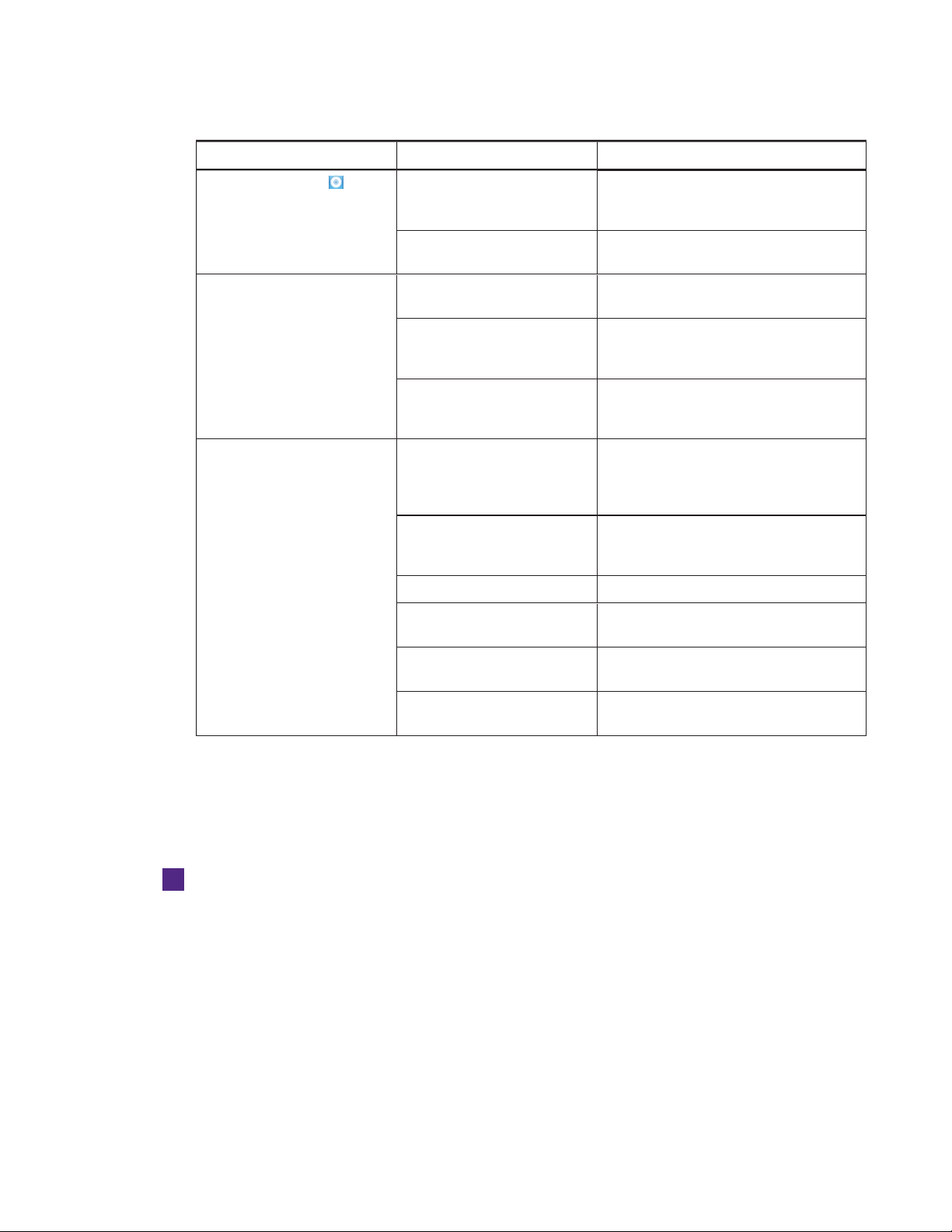
Symptom Cause Solut ion
The SMARTBoard icon doesn’t
appear.
Touch interactivity is slow. The connected computer is
Sound doesn’t play when you play
an audio file.
SMARTProductDrivers isn’t
installed.
SMARTProductDrivers isn’t
running.
running too many applications.
The connected computer doesn’t
meet SMART r equirements.
You haven’tused a USB 2.0 cable
to connect your interactive flat
panel to the computer.
The connected computer’s
playbackdevice isn’t set correctly
The interactive flat panel’s a udio
input isn’t set corr ectly.
The connected computer is muted. Turn off the mute setting.
The connected computer’s volume
is too low.
Download and install
SMARTProductDrivers from
smar ttech.com/downloads.
Start SMARTProductDrivers following the
steps in the Help.
Close some open applications.
Upgrade the computer or replace it with
another computer that meets system
requirements.
Use a USB 2.0 cable and ensure it’s
connected to the correct USB r eceptacle
(see page14).
Ensure the connected computer’s
playbackdevice is set as the interactive
flat panel (see the connected computer’s
documentation).
Ensure the intera ctiveflat panel’s audio
input is set as the computer’s audio
connector (see page37).
Turn up the volume on the computer.
Your interactive flat panel is muted. Turn off the mute setting using the front
control panel.
Your interactive flat panel’s volume
is too low.
Turn the volume up using the front control
panel.
Using the SMARTConnectionWizard
You can resolve a variety of issues using the SMART Connection Wizard found in SMARTSettings.
To use t h e SMAR T Connection Wizard
1. Access the SMART Connection Wizard by opening SMARTSettings (see
OpeningSMARTSettings
2. Press Con nection Wizard.
The
SMART Connection Wizard
3. Select your interactive flat panel from the list of connected SMART interactive products, and
then press Next .
on page22).
appears.
32 sm arttech.com/kb/170642
Page 41

CHAPTER 6
TROUBLESHOOTING
4. Select the option that best describes the issue you’re encountering, and follow the on-screen
instructions to troubleshoot your interactive flat panel.
Using SMARTBoard Diagnostics
If you touch the interactive flat panel’s surface and nothing happens, or if there is no digital ink or
the ink appears in some locations and not in others, use SMARTBoard Diagnostics to help identify
and resolve these issues.
IMPORTANT
Do not change diagnostic settings unless asked to do so by SMARTSupport.
To check camera views
1. Open SMARTSettings (see
2. Select About Soft ware and Product Support > Tools > Diagnostics.
SMARTBoard Diagnostics opens.
3. Select View > SPNL-6000/SBI D8000-G5 Bar.
The group box appears.
4. Press View.
The camera view screen appears.
5. Click Get image to display the four camera views. This could take a few moments.
If one of the camera views doesn’t appear, the camera is blocked or can’t locate the
reflective tape on the interactive flat panel’s inner frame.
NOTE
You can compare the camera view to examples of normal camera views.
6. Check the camera lens and ensure that nothing is blocking its view and that nothing is affixed
to the interactive surface.
OpeningSMARTSettings
on page22).
33 smarttech.com/kb/170642
Page 42

Page 43
Appendix A
Changing settings in the on-screen display menu 35
On-screen display menu options 36
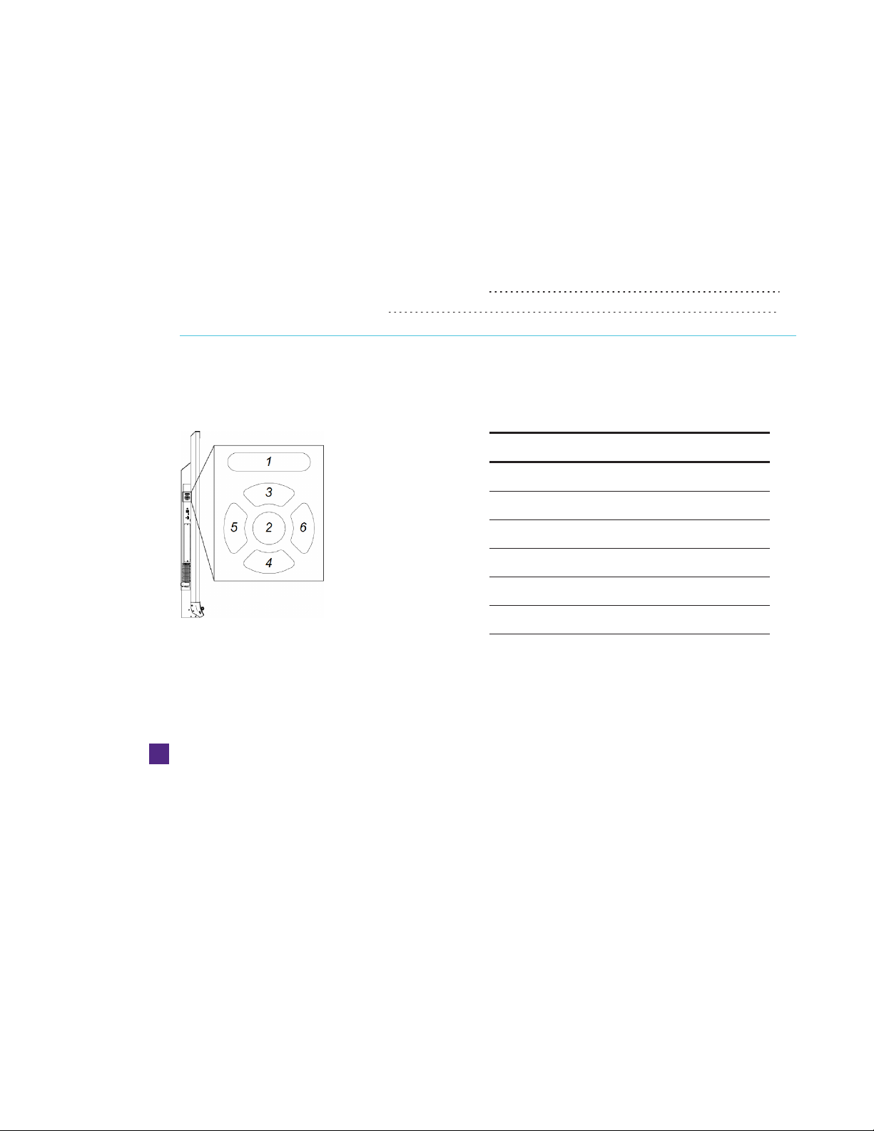
You can access the on-screen display menu using the menu control panel located on the side of
the interactive flat panel.
No. Name
1 MENU
2 SET
3 [Up]
4 [Down]
5 [Left]
6 [Right]
Changing settings in the on-screen display menu
To change sett ings in the on-screen display menu
1. Press the MENU button on the menu control panel.
The on-screen display menu appears.
2. Press the up and down arrows to highlight a menu, and then press SET.
3. Press the up and down arrows to highlight a menu option.
35 smarttech.com/kb/170642
Page 44
APPENDIX A
USING THE ON-SCREEN DI SPL AY M ENU
4. Press the left and right arrows to change the menu option’s setting.
OR
Press the right arrow to open the menu option’s submenu. (Repeat steps 3 and 4 to change
settings in the submenu.)
5. Press MENU until the on-screen menu closes.
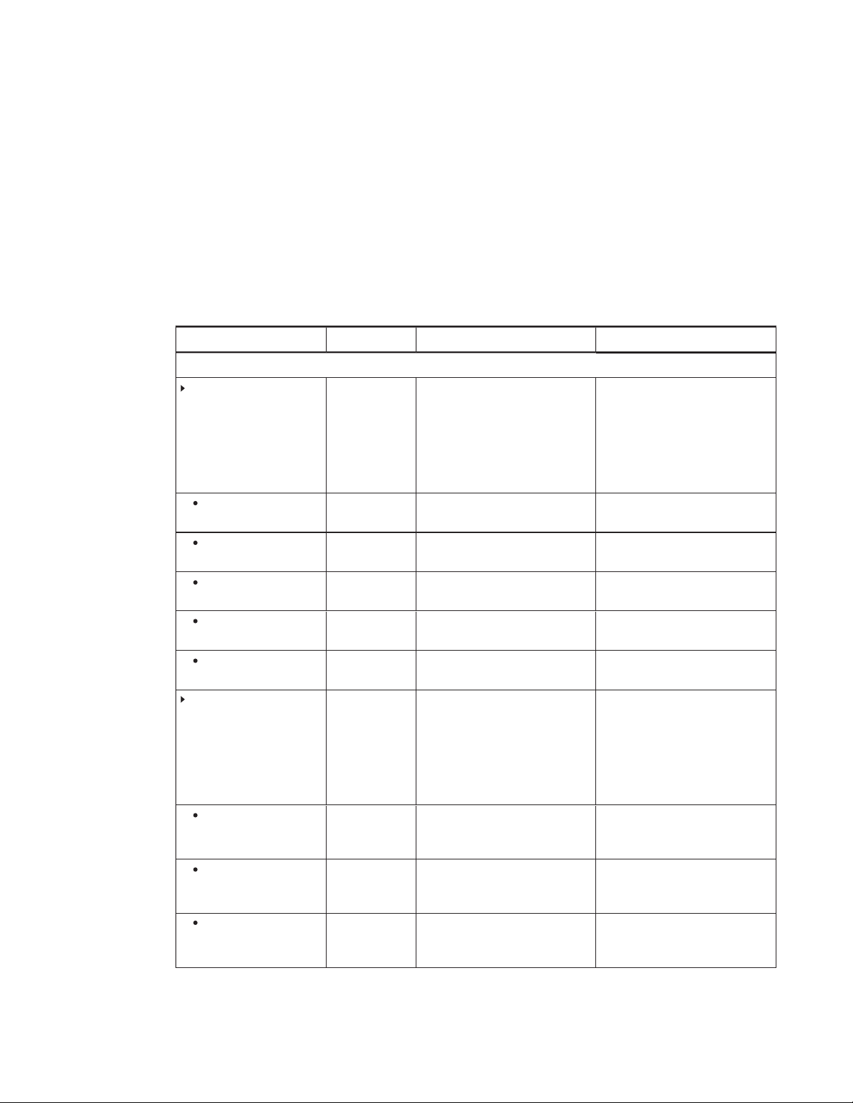
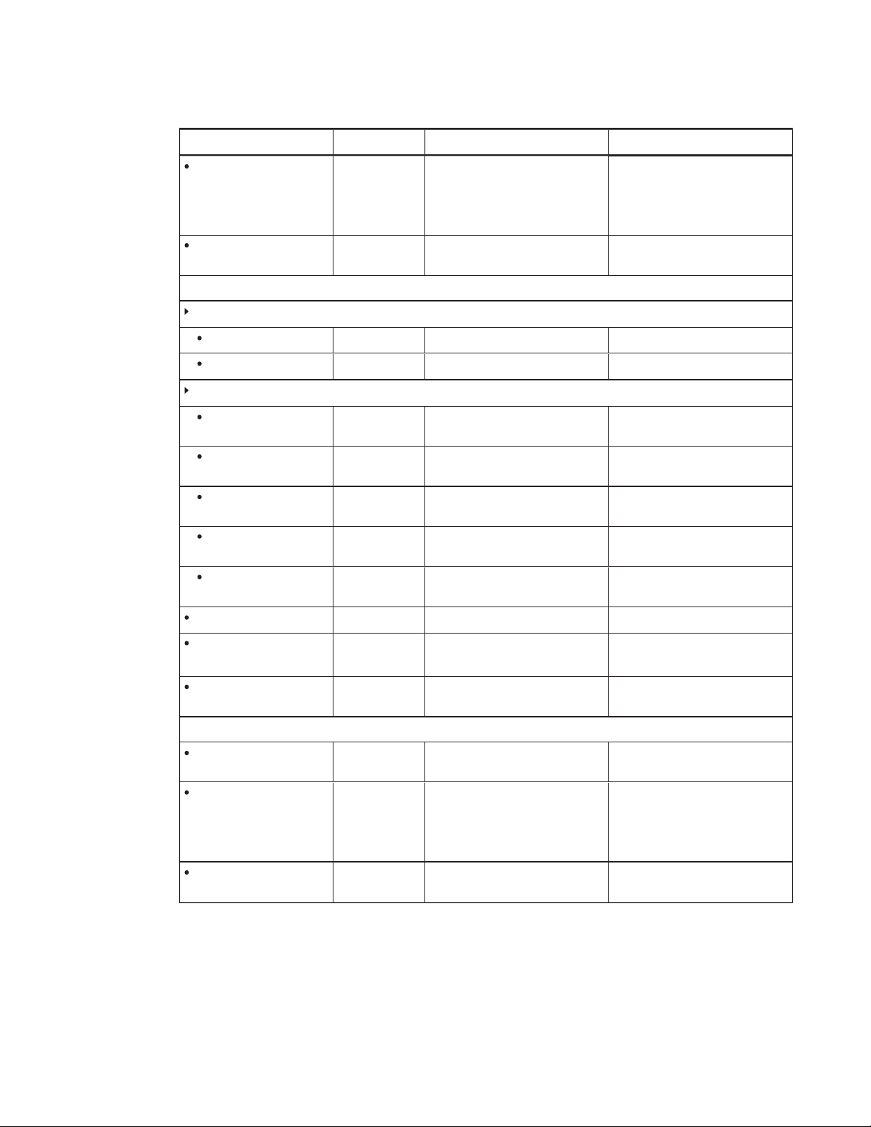
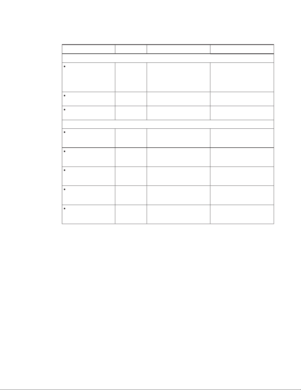
On-screen display menu options
Opti on Values Function Not es (i f any)
Pi cture
Picture Mode
Brightness
Contrast
Black Level
Color
Sharpness
Color temper ature
Standard
User
Dynamic
0–100 Sets the overall brightness of the
0–100 Sets the brightness of the image in
0–100 Sets the level of brightness in the
0–100 Sets the image color depth You can modifythis option only if
0–100 Sets the image sharpness You can modify this option only if
Norm al
Warm
User
Cool
Sets the picture mode Select User to customize
brightness, contrast, shar pness
and other
Select one of this option’s other
values to set brightness,contrast,
sharpness and other
options to default values.
You can modifythis option only if
image and background
relation to the background
darkest parts of the image
Sets the color temperature Select User to customize the
you select User in
You can modifythis option only if
you select User in
You can modifythis option only if
you select User in
you select User in
you select User in
amount of r ed, green and blue in
the image.
Select one of this option’s other
values to set the amount of red,
green and blue in the image to
default values.
Picture
options.
Picture
Picture Mode
Picture Mode
Picture Mode
Picture Mode
Picture Mode
.
.
.
.
.
Red
Green
Blue
36 smarttech.com/kb/170642
0–100 Sets the amount of red in the
image
0–100 Sets the amount of green in the
image
0–100 Sets the amount of blue in the
image
You can modifythis option only if
you select User in
Temperature
You can modifythis option only if
you select User in
Temperature
You can modifythis option only if
you select User in
Temperature
Color
.
Color
.
Color
.
Page 45
APPENDIX A
USING THE ON-SCREEN DI SPL AY M ENU
Opti on Values Function Not es (i f any)
Movie Mode
Picture Reset
Sound
Sound Mode
Treble
Bass
EQ
120 Hz
500 Hz
1.2 kHz
7.5 kHz
12 kHz
Off
Low
Middle
High
[N/A] Resets all options in the
L50–R50 Sets the high frequency sound
L50–R50 Sets the low frequency sound
0–100 Sets the sound equalization at
0–100 Sets the sound equalization at
0–100 Sets the sound equalization at
0–100 Sets the sound equalization at
0–100 Sets the sound equalization at
Sets the brightness,contrast, black
level, color and sharpness for
movie watching
Picture
menu to their default values
120Hz
500Hz
1.5kHz
5kHz
10kHz
Balance
Audio Input
Sound Reset
OSD
Language
OSDTurn Off
OSDReset
L50–R50 Balances the left and right volume
HDMI
USB
[N/A] Resets all options in the
[Languages] Sets the on-screen display menu’s
Off
5 seconds
10 seconds
15 seconds
[N/A] Resets all options in the
Sets the audio input source
Sound
menu to their default values
language
Sets the time of inactivity before the
on-screen display menu turns off
(in seconds)
OSD
menu
to their default values
37 smarttech.com/kb/170642
Page 46
APPENDIX A
USING THE ON-SCREEN DI SPL AY M ENU
Opti on Values Function Not es (i f any)
Setup
Power Save
Setup Reset
Factory Reset
About
Model Number
Serial N umber
Scalar firmware version
Touch firmware version
OPS Infor mation
On
Off
[N/A] Restores the setup settings to their
[N/A] Resets options in all menus to their
[N/A] Displays the interactive flat panel’s
[N/A] Displays the interactive flat panel’s
[N/A] Displays the interactive flat panel’s
[N/A] Displays the interactive flat panel’s
[N/A] Displays whether the OPS is
Enables or disables PowerSave
mode
default value
default values
model number
serial number
scalar firmware version
touch firmware version
installed
When Power Save mode is enabled
and there isn’tvideoinput, the
interactive flat panel displays
NoSignal
turning off.
This option only provides
information. You’re unable to
modify it.
This option only provides
information. You’re unable to
modify it.
This option only provides
information. You’re unable to
modify it.
This option only provides
information. You’re unable to
modify it.
This option only provides
information. You’re unable to
modify it.
for 25 seconds before
38 sm arttech.com/kb/170642
Page 47

Appendix B
interactiveflatpanel
Connecting and configuring a roomcontrolsystem 39
Connecting a computer to an interactive flat panel 40
Configuring the computer’s serial interface settings 40
Power modes 41
Room control system programming commands and responses 41
Command inventory 42
Viewing a list of available commands 42
Identifying current values 42
Assigning a specific value 42
Increasing a value for a setting 42
Decreasing a value for a setting 42
Designating video control settings for a specific video input 42
Identifying the value for a video control setting 43
Assigning a value for a video control setting 43
Commands 43
Power state 43
Source 44
Video control 44
Audio control 45
System information 47
This appendix includes detailed instructions on how to set up your computer or room control
system to remotely manage your interactive flat panel using an RS-232 serial interface.
Connecting and configuring a
roomcontrolsystem
Connect a computer to the room control input on the interactive flat panel to remotely select video
inputs, turn on or turn off the interactive flat panel and request information such as contrast, power
state and current settings.
39 smarttech.com/kb/170642
Page 48
APPENDIX B
REMOTEL Y MANAGING YOUR INTERACTIVEFL ATP ANEL
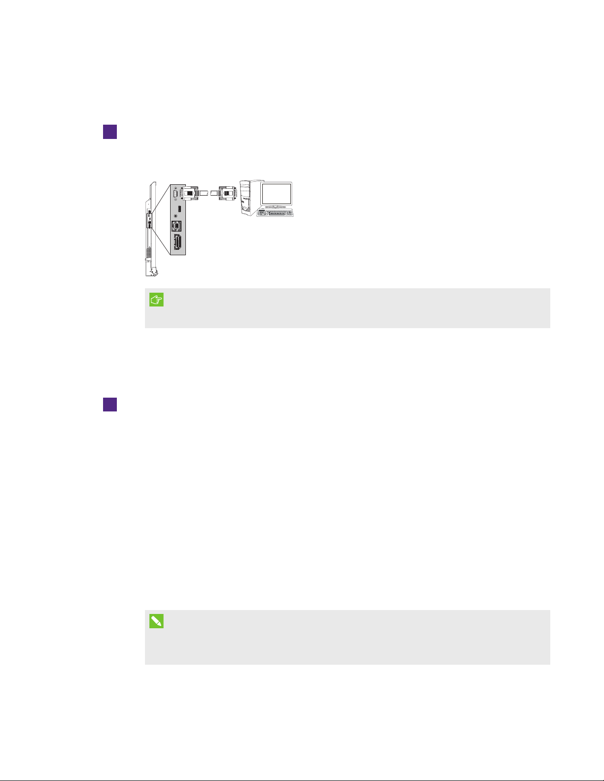
Connecting a computer to an interactive flat panel
To connect a comput er t o t he interact ive flat panel
Connect an RS-232 cable from the serial output on the computer to the room control input on
the connector panel.
IMPORTANT
Do not use a null modem cable. Use only a standard RS-232 cable.
Configuring the computer’s serial interface settings
You need to configure the computer’s serial interface before sending commands.
To configure t he comput er’s serial interface
1. Turn on the interactive flat panel.
2. Turn on the computer, and then start the serial communications program or terminal emulation
program.
3. Activate local echo.
4. Configure the serial interface settings using the following values, and then press ENTER.
Baud rate 19200
Data length 8
Parity bit None
Stop bit 1
A command prompt (>) appears on the following line.
NOTE
If no message appears or an error message appears, the serial interface configuration isn’t
correct. Repeat steps 3 and 4.
5. Type commands to configure the interactive flat panel.
40 smarttech.com/kb/170642
Page 49
APPENDIX B
REMOTEL Y MANAGING YOUR INTERACTIVEFL ATP ANEL
Power modes
An interactive flat panel has three distinct power modes:
l On
l Power Save
l Standby
All commands are available when the interactive flat panel is on. Some commands are available
when the interactive flat panel is in Standby mode.
Room control system programming commands and responses
To access interactive flat panel information or to adjust interactive flat panel settings using the
room control system, type commands after the command prompt (>), and then wait for the
response from the interactive flat panel.
CORR ECT
>get contrast
contrast=55
If you type a command that the room control system doesn’t recognize, you receive an invalid
command response.
In the example below the user included a space in the contrast command.
INCORRECT
>set con trast=65
invalid cmd=set con trast=65
NOTES
l Use ASCII formatted commands.
l Commands aren’t case-sensitive.
l Review each entry carefully before you press ENTER.
l Don’t send another command until you receive the response and the next command
prompt.
41 smar ttech.com/kb/170642
Page 50

APPENDIX B
REMOTEL Y MANAGING YOUR INTERACTIVEFL ATP ANEL
Command inventory
The interactive flat panel responds to the commands in the tables on the following pages.
Viewing a list of available commands
You can view a list of available commands by typing ? at the command prompt.
Identifying current values
You can identify the current value for each setting. In the example below, the user wants to identify
the contrast level for the interactive flat panel.
>get contrast
contrast=55
Assigning a specific value
You can assign a specific value for a setting within the command’s target range. In the example
below, the user wants to set the contrast level for the interactive flat panel to 65.
>set contrast=65
contrast=65
Increasing a value for a sett ing
You can increase a setting by a designated number. In the example below, the user wants to
increase the contrast level for the interactive flat panel by 5.
>set contrast +5
contrast=70
Decreasing a valu e for a sett ing
You can decrease a setting by a designated number. In the example below, the user wants to
decrease the contrast level for the interactive flat panel by 15.
>set contrast -15
contrast=55
Designating video control settings for a specific video input
When you connect multiple video inputs to the interactive flat panel, you can designate different
settings for each video input. You can also specify which video input you want to get information
about or assign values to.
NOTE
You must connect the video input to the interactive flat panel to identify or assign a value for it,
but the video input doesn’t need to be in use.
42 smarttech.com/kb/170642
Page 51
APPENDIX B
REMOTEL Y MANAGING YOUR INTERACTIVEFL ATP ANEL
Identifying the value for a video control setting
Use the get command to identify values for a video control setting. In the example below, the user
wants to identify the contrast for the HDMI1 video input.
>get contrast hdmi1
contrast hdmi1=65
Assigning a value for a video cont rol setting
Use the set command to assign values for a video control setting. In the example below, the user
wants to set the contrast to 70 for the HDMI1 video input.
>set contrast hdmi1=70
contrast hdmi1=70
Commands
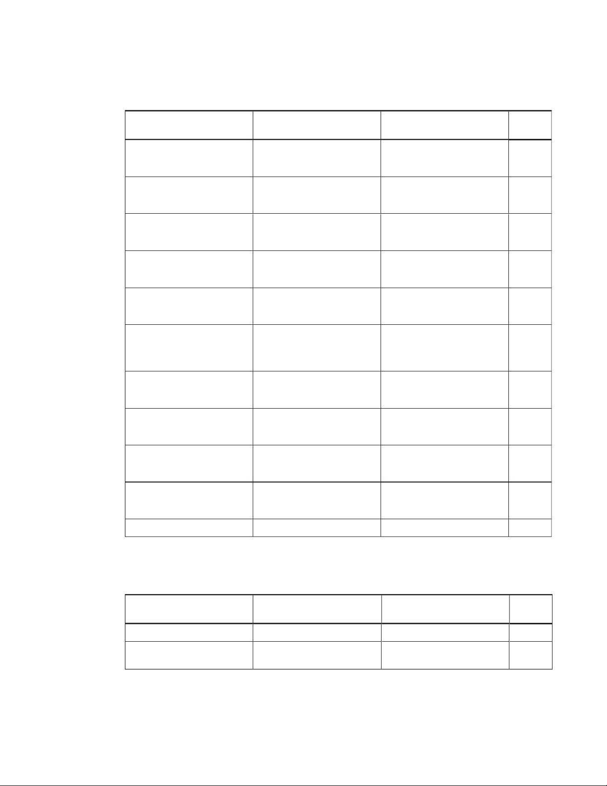
The following tables contain commands for your interactive flat panel.
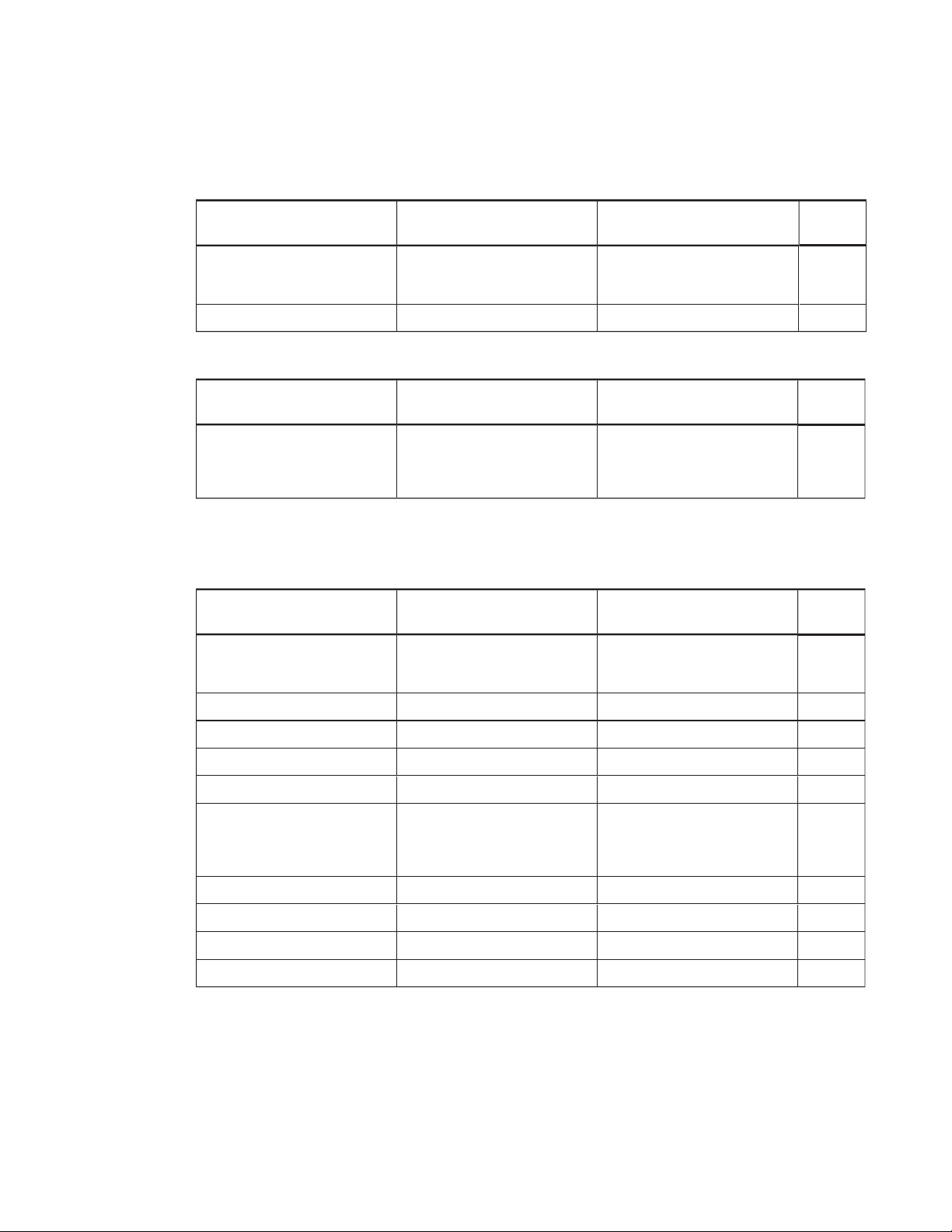
Power state
Use the following commands to identify power state settings.
Command Response P ossibl e values Standby
mode
get intpowerstate intpowerstate=
get powerstate powerstate=
Use the following commands to assign power state settings.
Command Possi ble values Response Standby
set power state
[Value]
l =on
l =off
l =standby
[Value]
[Value]
l on
l standby
l dpms
l novideo
l confirm
l proximitywait
l welcome
l on
l off
l standby
powerstate=
[Value]
Yes
Yes
mode
Yes
43 smarttech.com/kb/170642
Page 52
APPENDIX B
REMOTEL Y MANAGING YOUR INTERACTIVEFL ATP ANEL
Source
Use the following commands to identify source settings.
Command Response P ossible values Standby
mode
get input input=
get videoinputs videoinputs=
[Value]
[Value]
l hdmi1
l ops/hdmi2
l displayport
hdmi1,ops/hdmi2,displayport Yes
Yes
Use the following commands to assign source settings.
Command Possi ble values Response Standby
mode
set input
[Value]
l =hdmi1
l =ops/hdmi2
l =displayport
l =next
input=
[Value]
Yes
Video control
Use the following commands to identify video control settings.
Command Response P ossible values Standby
mode
get displaymode displaymode=
get contrast contrast=
[Value]
[Value]
l standard
l user
l dynamic
0–100 No
No
get brightness brightness=
get tint tint=
[Value]
get sha rpness sharpness=
get colortemp colortemp=
get red red=
get green green=
get blue blue=
[Value]
[Value]
[Value]
get blacklevel blacklevel=
44 smarttech.com/kb/170642
[Value]
[Value]
[Value]
[Value]
0–100 No
0–100 No
0–100 No
l normal
l warm
l cool
l user
0–100 No
0–100 No
0–100 No
0–100 No
No
Page 53
APPENDIX B
REMOTEL Y MANAGING YOUR INTERACTIVEFL ATP ANEL
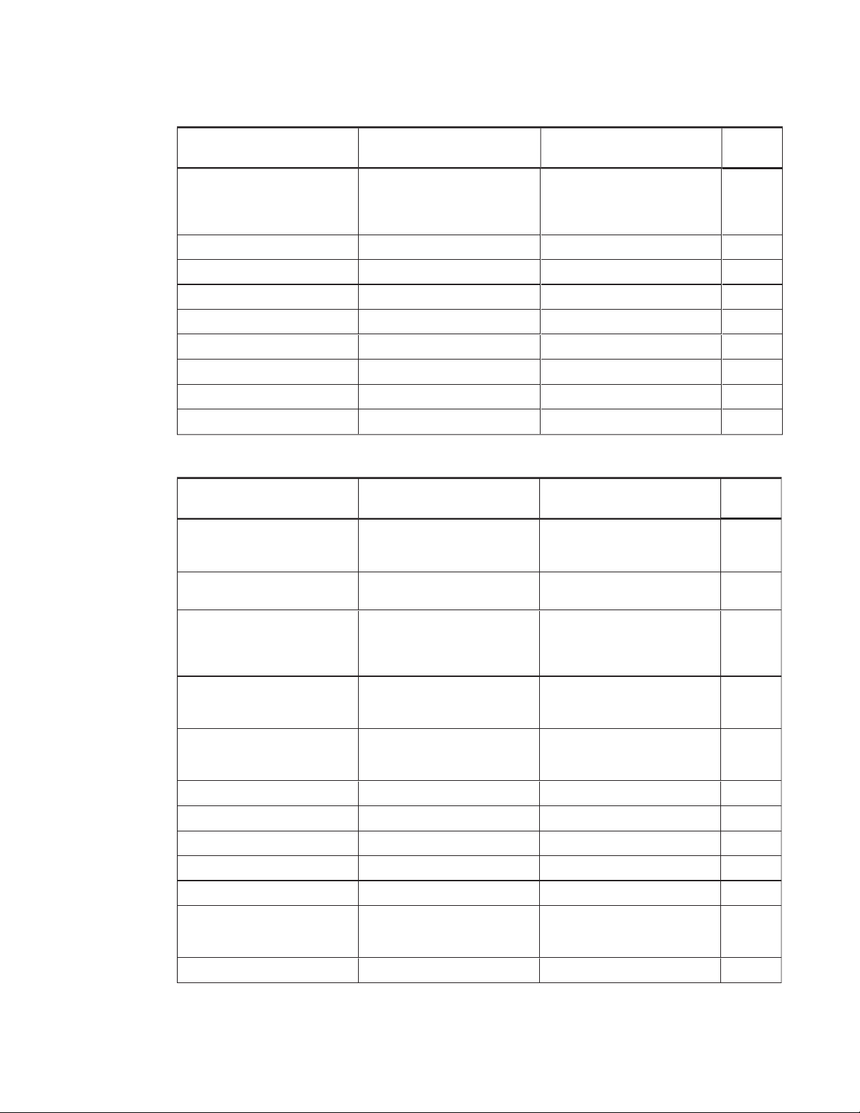
Use the following commands to assign video control settings.
Command Possi ble values Response Standby
mode
set displaymode
set contrast
[Value]
set br ightness
set tint
[Value]
set sharpness
set colortemp
set r ed
[Value]
set gr een
[Value]
[Value]
[Value]
[Value]
[Value]
l =standar d
l =user
l =dynamic
l +
[Incremental value]
l -
[Incremental value]
l =0–10 0
l +
[Incremental value]
l -
[Incremental value]
l =0–10 0
l +
[Incremental value]
l -
[Incremental value]
l =0–10 0
l +
[Incremental value]
l -
[Incremental value]
l =0–10 0
l =normal
l =war m
l =cool
l =user
l +
[Incremental value]
l -
[Incremental value]
l =0–10 0
l +
[Incremental value]
l -
[Incremental value]
l =0–10 0
displaymode=
contrast=
[Value]
brightness=
tint=
[Value]
sharpness=
colortemp=
red=
green=
[Value]
[Value]
[Value]
[Value]
[Value]
[Value]
No
No
No
No
No
No
No
No
set blue
[Value]
set blacklevel
set picturereset
[Value]
[Value]
l +
[Incremental value]
l -
[Incremental value]
l =0–10 0
l +
[Incremental value]
l -
[Incremental value]
l =0–10 0
blue=
blacklevel=
=yes picturereset=
[Value]
[Value]
[Value]
No
No
No
Audio control
Use the following commands to identify audio control settings.
Command Response P ossibl e values Standby
mode
get volume volume=
get mute mute=
45 smarttech.com/kb/170642
[Value]
[Value]
0–100 No
l on
l off
No
Page 54
APPENDIX B
REMOTEL Y MANAGING YOUR INTERACTIVEFL ATP ANEL
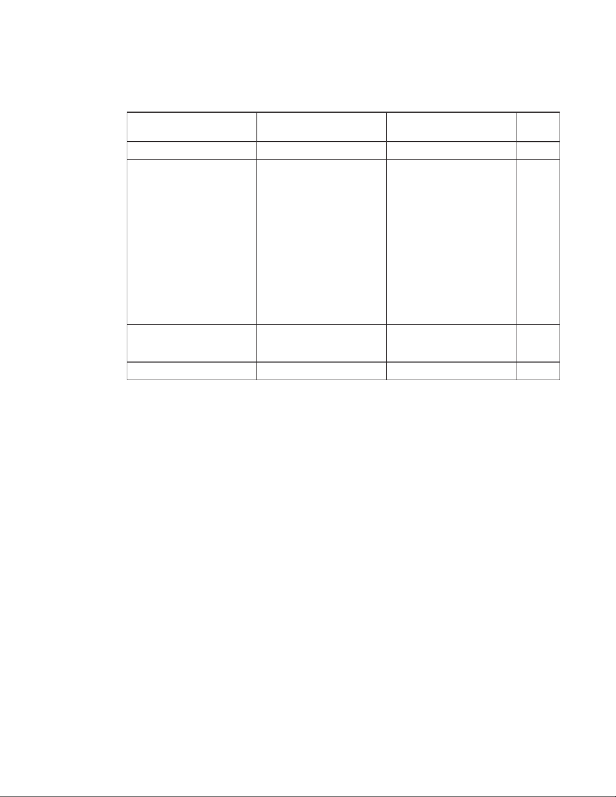
Command Response P ossibl e values Standby
mode
get audioinput audioinput=
get treble treble=
get bass bass=
get audioeq120 audioeq120=
get audioeq500 audioeq500=
get audioeq1200 audioeq1200=
get audioeq7500 audioeq7500=
get audioeq12k audioeq12k=
get balance balance=
[Value]
[Value]
[Value]
[Value]
[Value]
[Value]
[Value]
[Value]
[Value]
l usbaudio
l HDMI
l DisplayPort
l OPSdigital
0–100 No
0–100 No
0–100 No
0–100 No
0–100 No
0–100 No
0–100 No
0–100 No
No
Use the following commands to assign audio control settings.
Command Possi ble values Response Standby
mode
set volume
set m ute
[Value]
[Value]
l +
[Incremental value]
l -
[Incremental value]
l =0–10 0
l =on
l =off
volume=
mute=
[Value]
[Value]
No
No
set a udioinput
set tr eble
set bass
[Value]
[Value]
[Value]
set a udioeq120
set a udioeq500
set a udioeq1200
set a udioeq7500
set a udioeq12k
set balance
[Value]
set soundreset
[Value]
[Value]
[Value]
[Value]
[Value]
[Value]
l =usbaudio
l =HDMI
l =DisplayPort
l =OPSDigital
l +
[Incremental value]
l -
[Incremental value]
l =0–10 0
l +
[Incremental value]
l -
[Incremental value]
l =0–10 0
audioinput=
treble=
bass=
[Value]
=0–100 audioeq120=
=0–100 audioeq500=
=0–100 audioeq1200=
=0–100 audioeq7500=
=0–100 audioeq12k=
l +
[Incremental value]
l -
[Incremental value]
l =0–10 0
balance=
=yes soundreset=
[Value]
[Value]
[Value]
[Value]
[Value]
[Value]
[Value]
[Value]
[Value]
No
No
No
No
No
No
No
No
No
No
46 smarttech.com/kb/170642
Page 55

APPENDIX B
REMOTEL Y MANAGING YOUR INTERACTIVEFL ATP ANEL
System information
Use the following commands to identify system information settings.
Command Response P ossible values Standby
mode
get fwverscr fwverscr=
[Value] [Scaler version firmware
get fwvertouch fwvertouch=
get ser ialtouch serialtouch=
get opsinfo opsinfo=
[Value]
get language language=
get modelnum modelnum=
number]
[Value] [Touch controller firm war e
version number]
[Value] [Touch controller serial
number]
l OPS
l NO OPS
[Value]
l English
l Arabic
l Danish
l German
l Spanish
l Finnish
l French
l Hebrew
l Italian
l Dutch
l Norwegian
l Portuguese
l Russian
l Swedish
l Turkish
l Chinese_sim
[Value] [Model number ]
Yes
Yes
No
No
get ser ialnum serialnum=
[Value] [Serial num ber]
get proximityinstalled proximityinstalled=
get monitorid monitorid=
[Value]
47 smarttech.com/kb/170642
[Value]
No
l yes
l no
1–100 No
Page 56
APPENDIX B
REMOTEL Y MANAGING YOUR INTERACTIVEFL ATP ANEL
Use the following commands to assign system information settings.
Command Possi ble values Response Standby
mode
set fa ctoryreset
set language
set m onitorid
[Value]
[Value]
set touchdetected
[Value]
[Value]
=yes factoryreset=
l =English
l =Arabic
l =Danish
l =German
l =Spanish
l =Finnish
l =French
l =Hebrew
l =Italian
l =Dutch
l =Norwegian
l =Portuguese
l =Russian
l =Swedish
l =Turkish
l =Chinese_sim
l +
[Incremental value]
l -
[Incremental value]
l =1–100
l =yes touchdetected=
language=
monitorid=
[Value]
[Value]
[Value]
Yes
No
No
[Value]
48 sm arttech.com/kb/170642
Page 57

Appendix C
compliance
SMARTTechnologies supports global efforts to ensure that electronic equipment is manufactured,
sold and disposed of in a safe and environmentally friendly manner.
Waste Electrical and Electronic Equipment (WEEE)
Electrical and electronic equipment contain substances that can be harmful to the
environment and to human health. The crossed-out wheeled bin symbol indicates that
products should be disposed of in the appropriate recycling stream and not as regular
waste.
More information
See smarttech.com/compliance for more information.
49 smarttech.com/kb/170642
Page 58

Page 59

Index
A
air conditioning 10, 27
aspect ratio 3
audio
about 2
configuring 37, 45
controlling volume 4
muting 4
troubleshooting 32
B
balance, audio 37, 46
bass 37, 46
batteries 49
black level 36, 44
brightness 36, 44
C
contrast 36, 44
control panels
front Seefront control panel
menu Seemenu control panel
D
DisplayPort 44
documentation 7
doors 10
dry-erase markers 25
dust 10, 26
E
ECO Standby mode 41
eraser 5
F
calibration 19, 23-24, See alsoorientation
cameras
about 4
cleaning 26
chemicals 26
cleaning
camera windows 26
reflective tape 26
screen 25
color temperature 44
computer
connecting 14
condensation 27
connection wizard 19
connector panel 13
51 smarttech.com/kb/170642
factory reset 38
firmware updates 22
front control panel
about 4
G
gates 10
gestures 2
glass cleaner 25
H
hardware installation 9, 25
hardware removal 27
HDMI 14, 44
Page 60

INDEX
height for mounting your interactive flat
panel 11
humidity 26-27
I
installation
hardware Seehardware installation
software Seesoftware installation
installation instructions 7
K
knowledge base 6
L
languages 37, 47
local building codes 9
location for mounting your interactive flat
panel 10
M
M8 screws 10
maintenance 21
markers 25
menu control panel 35
mounting instructions 9
multitouch capabilities 2
multiuser sketch support 2
mute Seeaudio
O
object awareness 2
on-screen display menu 35
orientation 19, 23-24, See alsocalibration
P
packaging 28
Pen ID 2
pens
about 5
maintaining 27
permanent markers 25
power 10, 14, 17, 41, 43
presence detection sensors
configuring 47
R
recessed areas 10
reflective tape channel 4, 26
remote management 39
reset 21
room control 39
RS-232 39
S
serial number 47
serial numbers 29, 38
sharpness 36, 44
SMART Ink
about 6
installing 18
updating 23
SMART Notebook software
about 6
installing 18
updating 23
SMART Product Drivers
about 6
installing 18
updating 23
SMART Product Update 23
SMART Settings 22
smoke 26
software installation 18
software updates 23
sound Seeaudio
speakers
external 15
52 sma rttech.com/kb/170642
Page 61

INDEX
included with your interactive flat
panel 2, 5, 45
specifications 7
stand 28
Standby mode 38, 41, 43
sunlight 27
Support center 6
system administrator’s guides 7
T
tint 44
training 6
transportation 28
treble 37, 46
U
updates
firmware 22
software 23
USB cables and connectors 14
V
vacuum cleaners 26
ventilation 10, 26
VESA mounting plate 9
vibrations 10
volume Seeaudio
W
wall mounting instructions Seemounting
instructions
water 26
WEEE Directives 49
53 smarttech.com/kb/170642
Page 62

Page 63

Page 64

SMAR TTECHNOLOGI ES
smar ttech.com/support
smar ttech.com/contactsupport
smar ttech.com/kb/170642
 Loading...