

Page 1
WATCHDOG
Cinema Status Monitor for
up to 32 cinemas
Easy-to-see LED indication
of cinema status
Serial Data Buss for simple
wiring
Multiple units from same
data buss.
Works with SMART
Showmation and Panalogic
Automation Systems
Audible and Visual film
break alarms
UL Approved power pack
and electrical mounting box
watchdog manual D.p65
CINEMA STATUS PANEL
INSTALLATION AND
OPERATION MANUAL
Devices, Inc.
Copyright 2000 by SMART Devices, Inc.
5945 Peachtree Corners East
Norcross, GA 30071-1337
1-800-45-SMART
or
770-449-6698
Page 2

WATCHDOG STATUS PANEL
Devices, Inc.
CONTACT
SMART can be reached by telephone from 8:00 AM to 5:00 PM Monday - Friday if you have ques-
tions or need technical support regarding this or any other SMART product. The phone number is
toll free, 1-800-45-SMART (1-800-457-6278). The FAX number is 1-770-449-6728.
SMART is also available by e-mail at the following addresses:
service@smartdev.com for service questions or tech support
sales@smartdev.com for sales questions
engineering@smartdev.com for tech support
Visit the SMART WEB site at
http://www.smartdev.com
for new product information, on-line manuals, the SMART bulletin board,
and other information that may interest you.
LIMITED WARRANTY
SMART products and accessories are warranted against malfunction or failure due to defects in workmanship or
materials for a period of one year from the date of shipment. If a problem occurs during the warranty period, the unit
will be repaired, or replaced at our option, without charge for materials or labor. If air freight is requested by the dealer,
the difference between air and surface charges will be billed to the dealer. This limited warranty does not cover products that have been abused, altered, modified, or oper ated in other than specified conditions. Prior factory appro val is
required on all returns. Returned equipment or defective parts must be shipped freight prepaid to us by the dealer or
customer. Our limited warranty does not cover damages resulting from accident, misuse or abuse, lack of responsible
care, or failures not attributable to manufacturing defects, except as provided herein. SMART Devices, Inc. makes no
warranties, express or implied, including warranties of mer c hantability or fitness for a particular purpose. RETURN
POLICY: Factory authorization MUST be obtained before returning any product. A 15% restocking charge will be
issued on unused equipment (in original box) that is returned for credit. Credit is issued to the dealers account. The
credit may be used against future purc hases and no cash tr ansactions are offered. All returns must be shipped freight
prepaid by the dealer. Equipment returned without a factory RA (Return Authorization) will be refused.
Page 2
Page 3

INSTALLATION AND OPERATION MANUAL
Contents
CONTACT............................................................................................................................................. 2
LIMITED W ARRANTY........................................................................................................................... 2
INTRODUCTION ................................................................................................................................. 4
Specifications........................................................................................................................................ 4
INSTALLATION .................................................................................................................................... 5
Initial .................................................................................................................................................... 5
Configuration........................................................................................................................................ 5
Data Cable Wiring ................................................................................................................................ 6
RS232 Data Conncetions ...................................................................................................................... 6
Power Pack Connections....................................................................................................................... 6
Front Panels .......................................................................................................................................... 6
Final Assembly ...................................................................................................................................... 6
OPERATION ......................................................................................................................................... 6
Data Connection Terminals................................................................................................................... 6
Data Cable Routing and Connections ................................................................................................... 7
Page 3
Page 4
WATCHDOG STATUS PANEL
INTRODUCTION
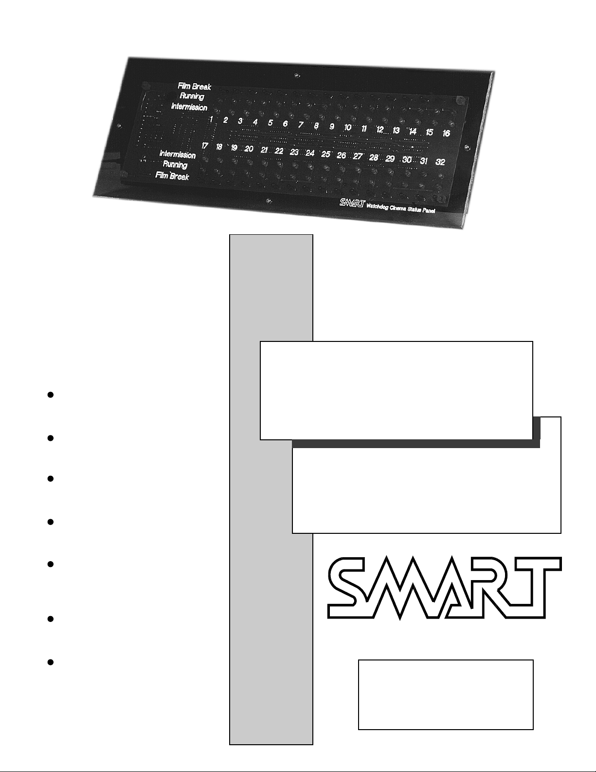
The SMART Watchdog Cinema Status Panel is the perfect complement to the SMART Showmation
Cinema Automation System. It provides a visual as well as an audible indication of the show status
in up to thirty two cinemas. Multiple Status Panels can be used in a multiplex, mounted in the
booth, at the concession stand, in the manager’s office, and anywhere else status information is
desired. The front panel is smoked acrylic through which a series of LED’s light to indicate either
INTERMISSION, RUNNING, or FILM BREAK. The front panel is available in either a horizontal or
vertical mounting configuration. A UL listed power pack and UL listed flush mount metal enclosure
is provided for the Status Panel. During a film break, a Red LED flashes and an audible alarm
sounds to alert the cinema staff to the break. The LED continues to flash until the film is repaired
and re-started. The audible alarm sounds for either 5 seconds or 10 seconds (alarm time is set by
the installer). The wiring interface is extremely simple consisting of only a 4 conductor + shield
cable (such as Belden 8723).
Specifications
The Watchdog Cinema Status Panel is a microcontroller based indicator panel which monitors
the show status of multiple cinemas.
Number of Cinemas 32 Screens max
Refresh Rate 3 Seconds max
Intermission Indication Orange LED
Serial Data Showmation
Formator
Panalogic Format
Configuration Master or Slave
Mounting Horizontal or
Vertical
Po wer Requirements 12 VDC to 16 VDC
300 mA
Running Indication Green LED
Film Break Indication Flashing Red LED
and Audible Alarm
Alarm Time 5 or 10 Seconds
Page 4
AC Line * 120 VAC,
0.5 Amps max
* P ower is supplied through a 120 VAC to 12
VDC Power Pack. For 220 VAC to 240 VAC
Page 5

INSTALLATION AND OPERATION MANUAL
INSTALLATION
Initial
The first step in the installation process is to determine the locations where the Status Panels will be
mounted. After this has been done, remov e the 4
thumbscrews that attach the front panels to the metal
enclosures, and set the front panels aside. The metal
enclosures must be placed into cutouts in the wall
using standard practices for mounting electrical
enclosures, and an electrician must provide 120 VAC
service to the duplex outlets located inside the metal
enclosures. The current requirement is less than 1/2
Ampere per Status Panel. The box may also be
surface mounted if desired, but this does not provide
very good cosmetics and should be av oided if
possible.
When the metal enclosure is installed, the outlet box
inside the enclosure must be located to the right if
horizontally mounted or to the bottom if vertically
mounted. If this is not done properly, the panel will
not fit in the enclosure.
The first option is Master/Slave. Only ONE of the
Status Panels can be set as Master, and the others
must be set as Slaves. Setting SW1-5 do wn selects
Slave mode. Up is Master Mode (factory setting)
The second option is the timer for the audible alarm.
This can be set for 5 seconds or 10 seconds. Setting
SW1-4 down selects 5 seconds. Up selects 10
seconds (factory setting).
The third option is for Horizontal or Vertical mounting. Setting SW1-3 down selects V ertical mounting.
Up selects Horizontal mounting (factory setting).
The fourth option is for Sho wmation data or RS232
data. This option is reserved for future use with other
automation systems (such as the Panalogic) or
computerized theatre information systems. Setting
SW1-2 down selects RS232 data. Up selects
Showmation data (factory setting). If you change this
factory setting, the unit will not work with the
SMART Showmations.
Configuration
The Status Panels ha ve several options which must
be set by the installer. Setting these options consists
of turning DIP switches ON or OFF. See Figure 1 for
DIP switch details.
SW1-1 is used for factory testing but may also be
used as a field troubleshooting aid. If SW1-1 is
down, then the LEDS will light up 8 at a time and
will sequence through 12 rows and repeat. This is a
good test to see if the basic hardware is operating
properly. Up is normal mode (factory setting).
DIP Switch Up Function Down Function
SW1-1 Normal Test
SW1-2 Showmation Data RS232 Data
SW1-3 Horizontal Ver tical
SW1-4 10 Second Alarm 5 Second Alar m
SW1-5 Master S l ave
DIP Switch SW1 located
near terminal strip end of
printed circuit board
FIGURE 1
Power Jack
Page 5
Page 6

WATCHDOG STATUS PANEL
Data Cable Wiring
If the data wiring has not previously been done, then
the wiring must be run from each automation system
to the Status Panel(s). See the section on Page 7
titled Data Cable Routing and Connections for
details. See Figure 2 on this page for the location of
the Data Connection Terminals on the Watchdog
printed circuit board.
RS232 Data Conncetions
If you ha ve ordered the Watchdog Panels for use
with a Panalogic Automation System, there will be a
separate page enclosed with this manual detailing
the connection procedures to follow for hookup.
Power Pack Connections
Connect the Power Pac k plug to J1 (sho wn in Figure
1). Plug the Po wer pack into the AC outlet mounted
inside the metal enclosure.
Front Panels
If you ha ve ordered horizontal and vertical front
panels, select the one which matches the mounting
orientation you hav e chosen. The Watchdog normally ships with the horizontal panels in place if
both panel types have been ordered. If vertical
mounting is desired, remove the circuit board from
the horizontal panel, and mount it on the vertical
panel.
Be careful to not overtorque the screws which
mount the pc board to the front panel as the acrylic
standoffs may be sheared off if too much torque is
applied.
Final Assembly
Dress the wires inside the metal enclosure, and
secure the front panel/pc board assembly to the
metal enclosure with the 4-40 thumb screws.
OPERATION
The Watchdog Cinema Status Panel is completely
automatic in normal operation. It is only necessary to
look at the panel to see the status in all cinemas. In the
event of a film break, the red LED will flash and the
audible alarm will sound. The alarm will stop after the
time out period (5 or 10 seconds as set up by the
installer). The LED will continue to flash until the break
has been repaired and the projector re-started. Inter mission is indicated by an orange LED and running by
a green LED.
Page 6
FIGURE 2
Data Connection Terminals
Page 7

INSTALLATION AND OPERATION MANUAL
Data Cable Routing and Connections
PLEASE NOTE:
It is necessary to minimize the total length of wiring between all Watchdog Panels and Showmation boards.
This is to keep signal degr adation to a minimum. If there is too much total cable length which causes the cable
capacitance to rise too high, then the system will cease working. Also remember that different types of cables
exhibit different capacitance per foot, so a total length of one type of cable may not work w hile another type
of cable of the same length may work properly.
We recommend the use of a four conductor cable suc h as Belden 8723 or its equivalent. Note that in ALL
cases, the SHIELD of the cable is cut off and not connected at all. This has been found to significantly reduce
cable capacitance and allow longer lengths of cable to be run.
Please refer to the typical wiring diagrams on this page and on Page 8 for a good overview of proper cable
routing and connections.
FIGURE 3
Page 7
Page 8

WATCHDOG STATUS PANEL
Page 8
FIGURE 4
Devices, Inc.
watchdog manual D.p65
 Loading...