

Page 1
SSM-TEN103132 | 98-4000932 | Version 3.2
EN
Accessories for Central inverter
SUNNY STRING-MONITOR
Technical Description
Page 2

Page 3

SMA Solar Technology AG Table of Contents
Technical Description SSM-TEN103132 3
Table of Contents
1 Notes on this manual. . . . . . . . . . . . . . . . . . . . . . . . . . . . . . 7
1.1 Validity . . . . . . . . . . . . . . . . . . . . . . . . . . . . . . . . . . . . . . . . . . . . 7
1.2 Target Group . . . . . . . . . . . . . . . . . . . . . . . . . . . . . . . . . . . . . . . 7
1.3 Additional Information . . . . . . . . . . . . . . . . . . . . . . . . . . . . . . . . 7
1.4 Symbols Used . . . . . . . . . . . . . . . . . . . . . . . . . . . . . . . . . . . . . . . 8
2 Safety . . . . . . . . . . . . . . . . . . . . . . . . . . . . . . . . . . . . . . . . . . 9
2.1 Appropriate Usage. . . . . . . . . . . . . . . . . . . . . . . . . . . . . . . . . . . 9
2.2 Parallel Connection of Strings. . . . . . . . . . . . . . . . . . . . . . . . . . 10
2.2.1 Maximum Number of Connections per Measurement Input. . . . . . . . . . . . . 10
2.2.2 Reverse Current. . . . . . . . . . . . . . . . . . . . . . . . . . . . . . . . . . . . . . . . . . . . . . . 11
2.3 Safety instructions . . . . . . . . . . . . . . . . . . . . . . . . . . . . . . . . . . . 12
2.3.1 Short-circuit current . . . . . . . . . . . . . . . . . . . . . . . . . . . . . . . . . . . . . . . . . . . . 12
2.3.2 Information on Grounded PV Plants . . . . . . . . . . . . . . . . . . . . . . . . . . . . . . . 13
2.3.3 Reverse Voltage . . . . . . . . . . . . . . . . . . . . . . . . . . . . . . . . . . . . . . . . . . . . . . 13
2.4 Personnel . . . . . . . . . . . . . . . . . . . . . . . . . . . . . . . . . . . . . . . . . 13
2.5 General Information . . . . . . . . . . . . . . . . . . . . . . . . . . . . . . . . . 13
3 Packing list . . . . . . . . . . . . . . . . . . . . . . . . . . . . . . . . . . . . . 14
3.1 Sunny String-Monitor . . . . . . . . . . . . . . . . . . . . . . . . . . . . . . . . 14
3.2 Identification of the Sunny String-Monitor. . . . . . . . . . . . . . . . . 14
3.3 Checking the Sunny String-Monitor for Transport Damage . . . 14
3.4 Storing the Sunny String-Monitor . . . . . . . . . . . . . . . . . . . . . . . 14
3.5 Structure of the Sunny String-Monitor . . . . . . . . . . . . . . . . . . . . 15
4 Mounting. . . . . . . . . . . . . . . . . . . . . . . . . . . . . . . . . . . . . . . 17
4.1 Selecting the Mounting Location. . . . . . . . . . . . . . . . . . . . . . . . 17
4.2 Assembling the Sunny String-Monitor . . . . . . . . . . . . . . . . . . . . 18
5 Electrical Connection . . . . . . . . . . . . . . . . . . . . . . . . . . . . . 20
Page 4

Table of Contents SMA Solar Technology AG
4 SSM-TEN103132 Technical Description
5.1 Safety . . . . . . . . . . . . . . . . . . . . . . . . . . . . . . . . . . . . . . . . . . . . 20
5.2 Overview of the Connection Area . . . . . . . . . . . . . . . . . . . . . . 21
5.3 Closing and Opening the Sunny String-Monitor. . . . . . . . . . . . 23
5.4 Connecting the PV strings . . . . . . . . . . . . . . . . . . . . . . . . . . . . . 24
5.4.1 Connect the PV Strings to the Spring Clamp Terminals. . . . . . . . . . . . . . . . . 24
5.4.2 Connect the PV Strings to the SUNCLIX DC Plug Connectors. . . . . . . . . . . . 24
5.4.3 Connect the PV Strings to the Tyco, MC3 and MC4 Plugs. . . . . . . . . . . . . . 26
5.5 Connecting the DC Main Cable. . . . . . . . . . . . . . . . . . . . . . . . 26
5.6 Connecting to Ground . . . . . . . . . . . . . . . . . . . . . . . . . . . . . . . 27
5.7 Connecting the Data Cable . . . . . . . . . . . . . . . . . . . . . . . . . . . 28
5.7.1 Data Cable Properties. . . . . . . . . . . . . . . . . . . . . . . . . . . . . . . . . . . . . . . . . . 28
5.7.2 Connect the Data Cable Shield Contact. . . . . . . . . . . . . . . . . . . . . . . . . . . . 28
5.7.3 Connecting the Data Cable in the Sunny String-Monitor . . . . . . . . . . . . . . . 28
5.7.4 Connecting the Data Cable in the Sunny Central . . . . . . . . . . . . . . . . . . . . . 30
5.7.5 Terminating the Data Cable . . . . . . . . . . . . . . . . . . . . . . . . . . . . . . . . . . . . . 31
5.8 Connecting the Remote Tripping for the DC Circuit Breaker. . . 32
5.8.1 Dimensioning the Connection Cable for the Operating Current Release . . . 32
5.8.2 Dimension the Connection Cable for the Undervoltage Release . . . . . . . . . 34
5.8.3 Connect Shunt Release . . . . . . . . . . . . . . . . . . . . . . . . . . . . . . . . . . . . . . . . . 35
5.8.4 Connecting the Feedback Contact . . . . . . . . . . . . . . . . . . . . . . . . . . . . . . . . 35
5.9 Install Anti-Theft Protection . . . . . . . . . . . . . . . . . . . . . . . . . . . . 36
5.10 Identification of the Piggy-Back for Data Processing. . . . . . . . . 36
6 Commissioning . . . . . . . . . . . . . . . . . . . . . . . . . . . . . . . . . . 37
6.1 Commissioning the Sunny String-Monitor . . . . . . . . . . . . . . . . . 37
6.2 Switching On the Sunny String-Monitor . . . . . . . . . . . . . . . . . . 38
6.3 Disconnecting the Sunny String-Monitor . . . . . . . . . . . . . . . . . . 39
6.4 Reconnect the DC Circuit Breaker after Tripping . . . . . . . . . . . 40
7 Configure Sunny String-Monitor . . . . . . . . . . . . . . . . . . . . 41
7.1 Configure the Sunny String-Monitor via Sunny Central Control 41
Page 5

SMA Solar Technology AG Table of Contents
Technical Description SSM-TEN103132 5
7.1.1 Organizing the Configuration. . . . . . . . . . . . . . . . . . . . . . . . . . . . . . . . . . . . 41
7.1.2 Check the Serial Interface Settings at the Sunny Central Control . . . . . . . . . 42
7.1.3 Detecting Sunny String-Monitor. . . . . . . . . . . . . . . . . . . . . . . . . . . . . . . . . . . 42
7.1.4 Setting the Device Address . . . . . . . . . . . . . . . . . . . . . . . . . . . . . . . . . . . . . . 43
7.1.5 Deleting detected Sunny String-Monitor . . . . . . . . . . . . . . . . . . . . . . . . . . . . 43
7.2 Configure the Sunny String-Monitor with Sunny Data Control . 44
7.2.1 Setting the Required Values . . . . . . . . . . . . . . . . . . . . . . . . . . . . . . . . . . . . . 44
7.2.2 Configuring Sunny String-Monitor. . . . . . . . . . . . . . . . . . . . . . . . . . . . . . . . . 46
8 Function of the String Current Monitoring . . . . . . . . . . . . 48
8.1 Requirements for Activating the String Current Monitoring. . . . 48
8.2 Functionality of the String Current Monitoring . . . . . . . . . . . . . 48
8.3 Setting the Parameters Using Sunny Central Control . . . . . . . . 51
8.3.1 Setting the Number of Strings per Measuring Channel . . . . . . . . . . . . . . . . 51
8.3.2 Setting the Groups . . . . . . . . . . . . . . . . . . . . . . . . . . . . . . . . . . . . . . . . . . . . 52
8.3.3 Setting the Tripping Time. . . . . . . . . . . . . . . . . . . . . . . . . . . . . . . . . . . . . . . . 52
8.3.4 Setting the Tolerance. . . . . . . . . . . . . . . . . . . . . . . . . . . . . . . . . . . . . . . . . . . 53
8.3.5 Setting the Time Window . . . . . . . . . . . . . . . . . . . . . . . . . . . . . . . . . . . . . . . 53
8.3.6 Setting overnight shutdown . . . . . . . . . . . . . . . . . . . . . . . . . . . . . . . . . . . . . . 53
8.3.7 Setting Anti-Theft Protection . . . . . . . . . . . . . . . . . . . . . . . . . . . . . . . . . . . . . . 53
8.4 Setting the Parameters Using Sunny Data Control . . . . . . . . . . 54
8.4.1 Overview of the Program Window . . . . . . . . . . . . . . . . . . . . . . . . . . . . . . . . 54
8.4.2 Setting the Number of Strings per Measuring Channel . . . . . . . . . . . . . . . . 54
8.4.3 Setting the groups . . . . . . . . . . . . . . . . . . . . . . . . . . . . . . . . . . . . . . . . . . . . . 55
8.4.4 Setting the Time Window . . . . . . . . . . . . . . . . . . . . . . . . . . . . . . . . . . . . . . . 55
8.4.5 Setting the Tripping Time. . . . . . . . . . . . . . . . . . . . . . . . . . . . . . . . . . . . . . . . 55
8.4.6 Setting the Tolerance. . . . . . . . . . . . . . . . . . . . . . . . . . . . . . . . . . . . . . . . . . . 55
8.4.7 Setting overnight shutdown . . . . . . . . . . . . . . . . . . . . . . . . . . . . . . . . . . . . . . 56
8.4.8 Setting Anti-Theft Protection . . . . . . . . . . . . . . . . . . . . . . . . . . . . . . . . . . . . . . 56
8.5 Reading the Measurement Values in Sunny Central Control . . 56
8.5.1 Reading the Mean Values of the Groups . . . . . . . . . . . . . . . . . . . . . . . . . . . 56
8.5.2 Reading the Mean Values for the Individual Measurement Channels . . . . . 56
Page 6

Table of Contents SMA Solar Technology AG
6 SSM-TEN103132 Technical Description
8.6 Reading the Measurement Values in Sunny Data Control . . . . 57
8.7 Reading the Messages in Sunny Central Control . . . . . . . . . . . 58
8.7.1 Reading and Confirming Current Messages. . . . . . . . . . . . . . . . . . . . . . . . . 58
8.7.2 Reading and Confirming the Event History . . . . . . . . . . . . . . . . . . . . . . . . . . 58
9 Troubleshooting . . . . . . . . . . . . . . . . . . . . . . . . . . . . . . . . . 59
10 Technical data. . . . . . . . . . . . . . . . . . . . . . . . . . . . . . . . . . . 60
11 Contact . . . . . . . . . . . . . . . . . . . . . . . . . . . . . . . . . . . . . . . . 65
Page 7

SMA Solar Technology AG 1Notes on this manual
Technical Description SSM-TEN103132 7
1 Notes on this manual
1.1 Validity
This technical description describes the installation and operation the Sunny String-Monitor.
1.2 Target Group
This manual is intended for installers and operators of PV plants equipped with the Sunny Central and
Sunny String-Monitor.
1.3 Additional Information
You will find further information on the Sunny String-Monitor in the download area of
www.SMA.de/en. Keep the documentation of the Sunny String-Monitor and of the installed
components with the system documentation. They must be accessible at all times.
The documents listed below are included in the delivery of your Sunny String-Monitor. The following
information is contained in these documents.
• Technical Description Installation and operation of the Sunny String-Monitor
• Additional documentation
Page 8
1Notes on this manual SMA Solar Technology AG
8 SSM-TEN103132 Technical Description
1.4 Symbols Used
The following types of safety instructions and general information appear in this document:
☑ This symbol indicates the result of an action.
✖ This symbol indicates a possible error.
%"/(&3
"DANGER" indicates a hazardous situation which, if not avoided, will result in death or
serious injury.
8"3/*/(
"WARNING" indicates a hazardous situation which, if not avoided, could result in death
or serious injury.
$"65*0/
"CAUTION" indicates a hazardous situation which, if not avoided, could result in minor
or moderate injury.
/05*$&
NOTICE indicates a situation that can result in property damage if not avoided.
Information
Information provides tips that are important for the optimal operation of your product.
Page 9
SMA Solar Technology AG 2Safety
Technical Description SSM-TEN103132 9
2Safety
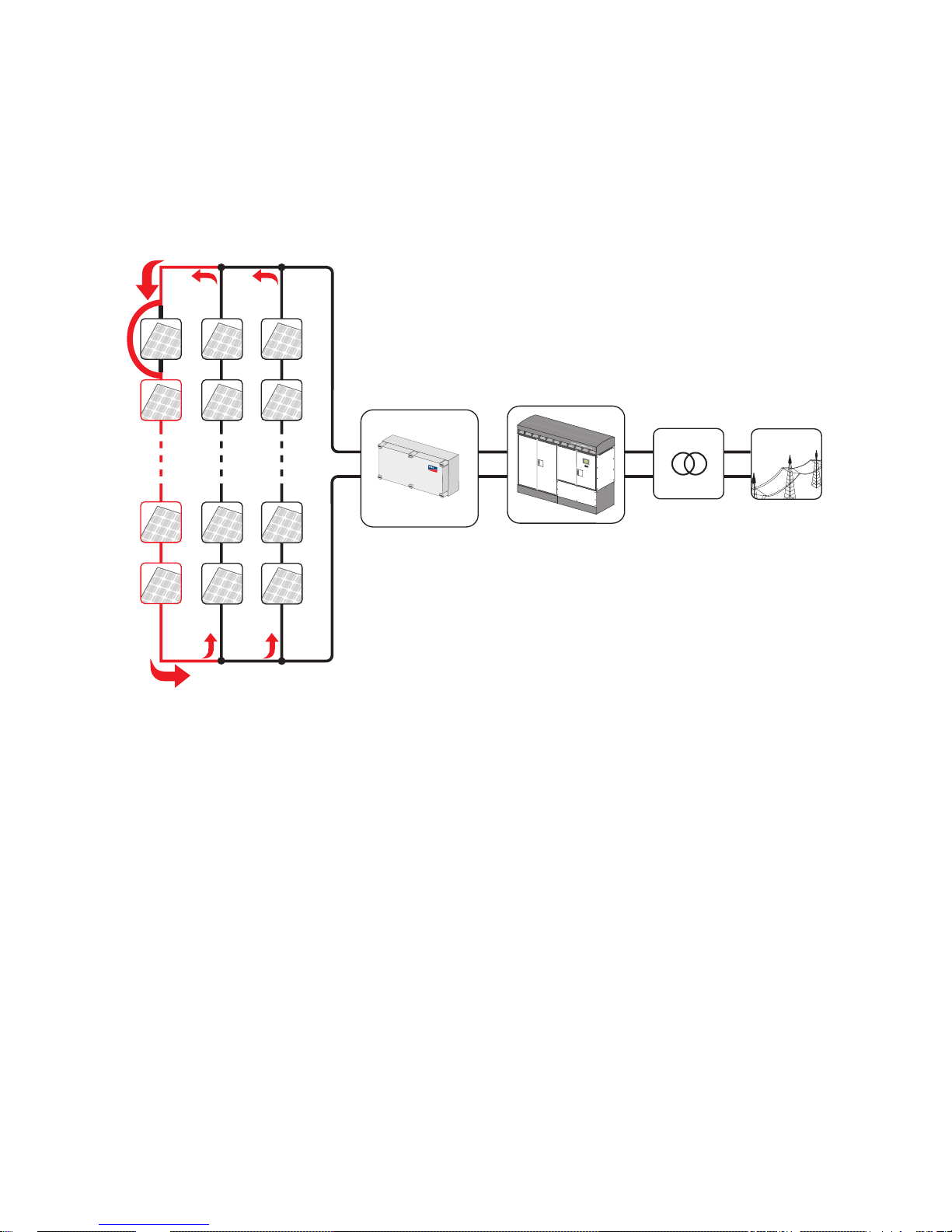
2.1 Appropriate Usage
The Sunny String-Monitor is an accessory for the Sunny Central central inverter. The DC subdistributor
offers the possibility of connecting several strings in parallel. The Sunny String-Monitor monitors and
recognizes outages and thus prevents loss of power and output. The string fuses in the Sunny StringMonitor disconnect defective strings which, for example, have been damaged due to a short-circuit
in the module or in the cabling of the PV array.
The Sunny String-Monitor allows monitoring of the integrated overvoltage protectors. The overvoltage
protectors protect the inverters from transient overvoltages.
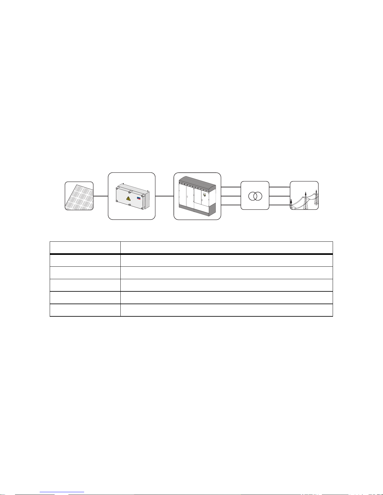
Figure1:Principle of a grid-tied PV plant
Position Description
APV array
B Sunny String-Monitor SSM
C Sunny Central
D Transformer
EPublic grid
A
B
C
D
E
S
M
A
S
U
N
N
Y
C
E
N
T
R
A
L
8
0
0
C
P
S
M
A
Page 10
2Safety SMA Solar Technology AG
10 SSM-TEN103132 Technical Description
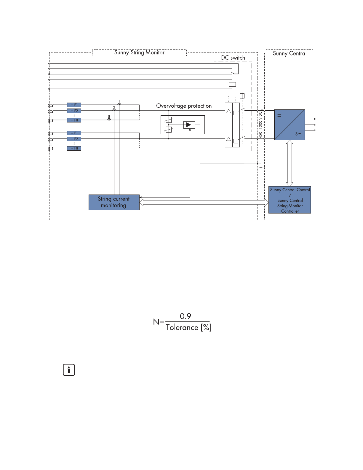
Figure2:Block circuit diagram of the Sunny String-Monitor in the PV system
2.2 Parallel Connection of Strings
2.2.1 Maximum Number of Connections per Measurement Input
Several PV strings can be connected in parallel in the Sunny String-Monitor. The maximum number of
PV strings connected in parallel depends on the adjustable tolerance, and can be determined as
follows:
N = maximum number of PV strings that can be connected in parallel.
The parameter "tolerance" can be adjusted in the Sunny Central Control.
Maximum Number of Strings
The maximum number of PV strings that can be connected in parallel is limited to 9, if the
tolerance is set to 10 %. If more than 9 PV strings are connected in parallel at this level
of tolerance, the failure of a PV string cannot be recognized.
• Adhere to the maximum number of PV strings which can be connected in parallel.
Page 11
SMA Solar Technology AG 2Safety
Technical Description SSM-TEN103132 11
2.2.2 Reverse Current
A reverse current may arise when different open circuit voltages are present at modules mounted in
parallel. In this event, the reverse current can be much higher than the module's short circuit current.
The higher the reverse current, the higher the heat will rise in the modules of the faulty PV strings.
Pronounced warming can destroy the modules of the faulty PV strings.
Figure3:Possible reverse currents in the PV array
The following points can cause a reverse current:
• Short circuit in one or more modules,
• Short circuit in one or more cells in a module
• Double ground fault in a module
• Double ground fault in the cabling
The Sunny String-Monitor contains string fuses. They trip when the string current is too high and thus
protect the modules of the faulty PV strings. The Sunny String-Monitor informs Sunny Central Control
of the failure of the PV strings. The Sunny Central Control displays the warning "SMU".
Page 12
2Safety SMA Solar Technology AG
12 SSM-TEN103132 Technical Description
2.3 Safety instructions
2.3.1 Short-circuit current
The short circuit current of the PV array is only slightly higher than the maximum operating current and
also depends on irradiation conditions. If a short-circuit occurs in the system, the available fuses are
not guaranteed to switch off.
%"/(&3
Risk of lethal electric shock.
• Work on the Sunny String-Monitor may only be performed after switching off the power to the
unit in accordance with the regulations applicable to the installation site:
– Disconnect
– Ensure that the device cannot be reconnected
– Ensure that no voltage or current is present
– Cover or isolate adjacent live elements
%"/(&3
Risk of lethal electric shock. The fuse holders are also energized when the string fuse is
disconnected.
• The Plexiglas covers must always be mounted, to ensure protection against direct touching.
• Only insert the fuses when wearing personal protective equipment.
• Only plug in or unplug the Solar Plug when no current is present.
8"3/*/(
Danger of electric shock due to incorrect procedure. Serious injuries, burns and material
damage.
• All work on the Sunny String-Monitor must be carried out strictly according to the instructions
in this guide.
• Observe all safety precautions.
• Wear personal protective equipment during work on electrical devices.
• Immediately rectify failures that affect or limit the safety of the device.
• Unauthorized personnel must not have access to the devices.
Warning Signs
• Signs must always be attached in prominent positions and must be promptly replaced if
damaged.
Page 13

SMA Solar Technology AG 2Safety
Technical Description SSM-TEN103132 13
2.3.2 Information on Grounded PV Plants
The positive or negative pole of the PV array can be grounded within the Sunny Central via a GFDI
(Ground Fault Detection Interruption) fuse.
• Additional grounding within the PV array or floor-mounted distribution board is not permissible.
The grounding of the PV array can be automatically interrupted by the GFDI at any time.
• The GFDI ensures plant protection, but does not protect persons.
You will find additional information on grounded PV plants in the Sunny Central documentation and
in the download area of www.SMA.de/en.
2.3.3 Reverse Voltage
On the main DC cables in the Sunny String-Monitor there is a permanent reverse voltage present of
up to 1000 VDC of the Sunny Central. When the power is off, the reverse voltage can be interrupted
by pulling the DC fuses in the Sunny Central.
2.4 Personnel
Only qualified technical personnel may perform work on the Sunny String-Monitor. Qualified means
that the personnel must possess training relevant to the activity performed and must be familiar with
the content of this manual.
2.5 General Information
Communication between Sunny String-Monitor and Sunny Central
Alongside the Sunny String-Monitor SSM one can also install the Sunny String-Monitor SSM16-11 as
well as the Sunny String-Monitor SSM24-11 for string monitoring These have various numbers of
Piggy-Backs for data processing.
Maximum number of Piggy-Backs for data processing
There are two communications connections in each Sunny Central, to which up to 10
Piggy-Backs each can be connected. The number of Piggy-Backs for data processing is
thus determined by the combination possibilities between the Sunny String-Monitor SSM,
Sunny String-Monitor SSM16-11 and Sunny String-Monitor SSM24-11. The following
summary shows the number of Piggy-Backs for data processing in the various Sunny
String-Monitor:
• Sunny String-Monitor SSM: 1 Piggy-Back for data processing.
• Sunny String-Monitor SSM16-11: 2 Piggy-Backs for data processing.
• Sunny String-Monitor SSM24-11: 3 Piggy-Backs for data processing.
Page 14
3Packing list SMA Solar Technology AG
14 SSM-TEN103132 Technical Description
3Packing list
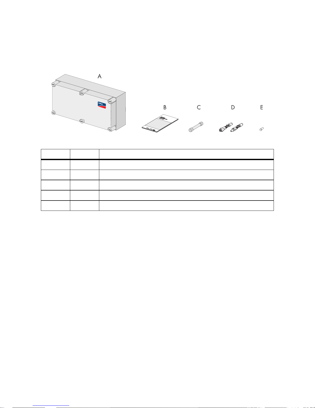
3.1 Sunny String-Monitor
Figure4:Packing list
3.2 Identification of the Sunny String-Monitor
The type label serves to identify the Sunny String-Monitor. The type label is found on the mounting
plate in the upper middle, next to the big measurement circuit board. On the type label there is the
following information:
• Type (Type / Model)
•Serial number (Serial No.) of the Sunny String-Monitor.
3.3 Checking the Sunny String-Monitor for Transport Damage
• Check the device and its packaging for damage.
• Compare the delivery contents against the delivery papers.
• If the device is damaged or if there are discrepancies in the content of the delivery, contact your
supplier.
3.4 Storing the Sunny String-Monitor
• Only store the Sunny String-Monitor in areas where it is protected from dust and dampness.
Position Number Description
A 1 Sunny String-Monitor
B 1 Technical description
C 8 / 16 Fuses
D 8 / 16 DC plug connector
*
*
optional
E 8 / 16 Sealing plugs for DC plug connectors
*
Page 15
SMA Solar Technology AG 3Packing list
Technical Description SSM-TEN103132 15
3.5 Structure of the Sunny String-Monitor
Depending on the option chosen, the Sunny String-Monitor may have a DC circuit breaker and may
be equipped with a different number or string connections. For the selection of Sunny String-Monitor
options or fittings use the option code in the price list. It determines both the assembly and recognition
of the Sunny String-Monitor.
Terminals, for the connection of the RS485 communication and the +55 V
DC
power supply are
provided in the connection area. In addition, the connection area provides a contact for the data
cable shield.
String monitoring takes place via the measurement circuit board in the Sunny String-Monitor, where a
Piggy-Back for data processing (SMU8HV-DVPB) is integrated. The SMU8HV-DVPB assumes string
current management and the measurement board's parameter settings. Two bolt clamps are
integrated into the Sunny String-Monitor to connect the DC main cable to the inverter.
The DC circuit breaker offers the option of disconnecting the Sunny String-Monitor on the inverter side.
In the case of grounded PV arrays, the positive or the negative pole can be grounded at the inverter.
In this case, cylindrical bridges are used instead of fuses in the Sunny String-Monitor.
For protection from transient overvoltages caused by lightning strikes, overvoltage protectors are built
into the Sunny String-Monitor. A grounding terminal is provided for connection of the equipotential
bonding.
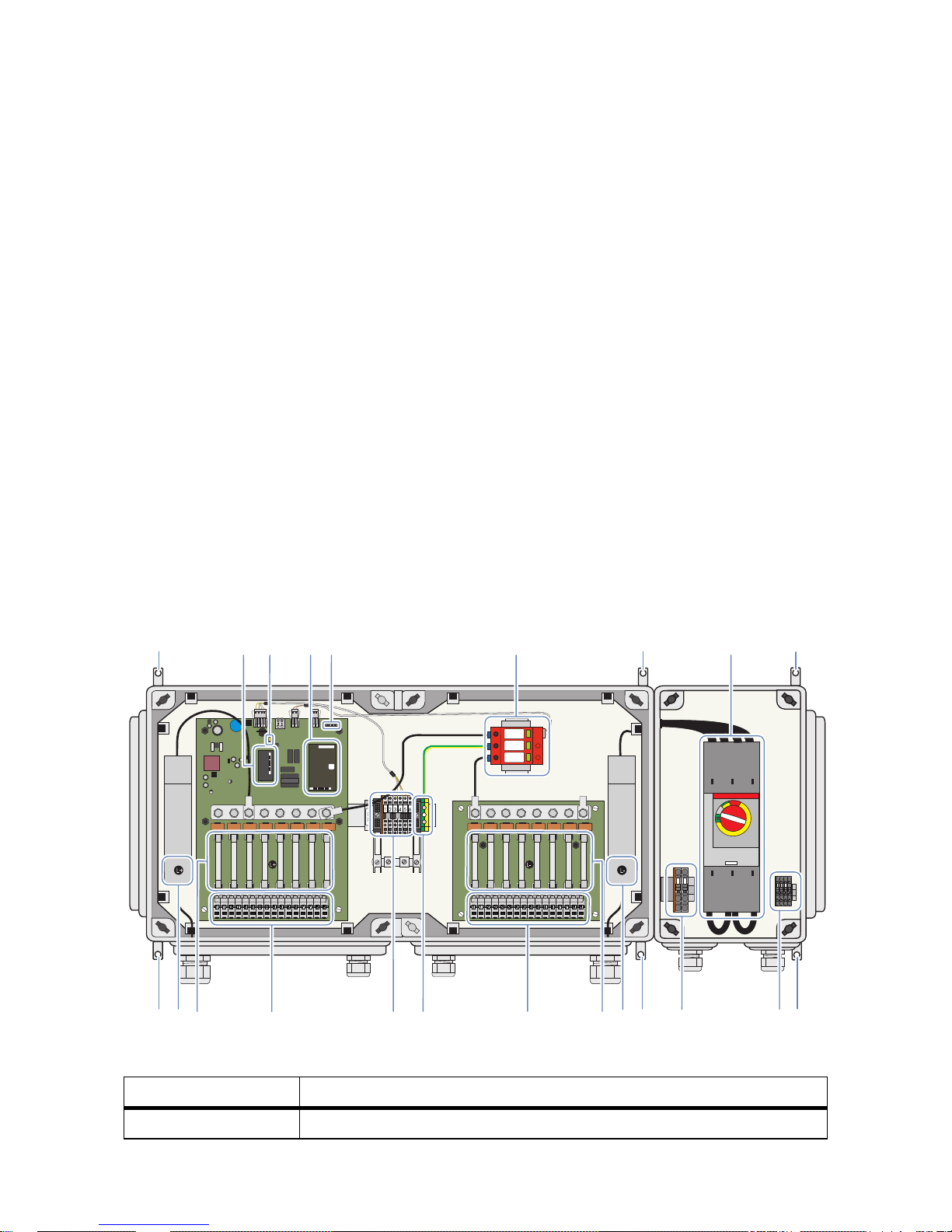
Depending on the selected fittings, the interior view of a Sunny String-Monitor can differ from the
depicted maximum assembly options.
Figure5:Main components inside
Position Description
A Mounting brackets
BC
DE
F
KLMNOPR
1 2
3 4 5 6
G
A
QA
A
A
A AHI
Page 16

3Packing list SMA Solar Technology AG
16 SSM-TEN103132 Technical Description
B Communication Piggy-Back
C Jumper for data cable termination
D Piggy-Backs for data processing
E Operating status LEDs
F Overvoltage protector
GDC circuit breaker
H Connection of the feedback signal contact
I Shunt release drive connection
K Main DC cable connection, ‒ pole
L DC fuses or cylindrical bridges
MString connections, ‒ pole
NGround connection
O Communication Connection
P String connections, + pole
Q DC fuses or cylindrical bridges
R Main DC cable connection, + pole
Position Description
Page 17
SMA Solar Technology AG 4Mounting
Technical Description SSM-TEN103132 17
4Mounting
4.1 Selecting the Mounting Location
• Do not install the Sunny String-Monitor in an emergency exit path, or in a living or office area.
• Choose a location which can support the weight of the Sunny String-Monitor.
• Choose a location with low interference field strengths.
• Mount the Sunny String-Monitor so as to allow easy access for service work.
• Mount the Sunny String-Monitor so that it is protected from direct irradiation.
• Mount the Sunny String-Monitor so that it is as protected from rain as is possible.
• Provide for external strain relief.
• Mount the Sunny String-Monitor level on a wall or a stand, so that the connection area is
pointing downward.
• Do not mount the Sunny String-Monitor flat on its back or leaning.
%"/(&3
Danger to life due to fire or explosion.
• Do not install the Sunny String-Monitor on flammable construction materials.
• Do not install the Sunny String-Monitor near highly flammable materials.
• Do not install the Sunny String-Monitor in potentially explosive areas.
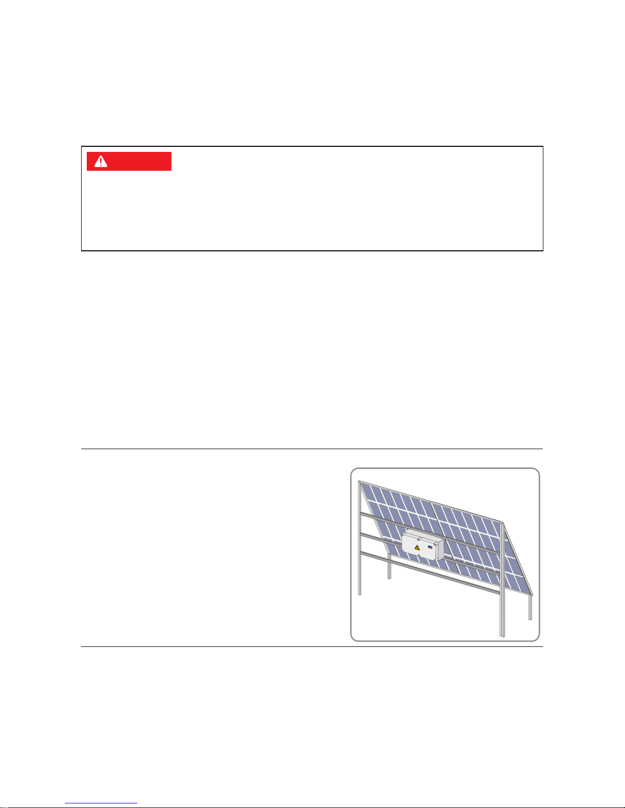
Example:
In the case of a rack-mounted PV array, the Sunny StringMonitor can ideally be positioned directly behind the PV
array in the shadow.
SM
A
Page 18
4Mounting SMA Solar Technology AG
18 SSM-TEN103132 Technical Description
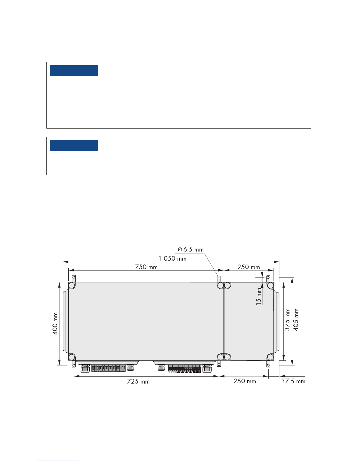
4.2 Assembling the Sunny String-Monitor
Required material:
• 6 screws, 6 mm diameter, 4 screws if no DC circuit breaker Consider the wall properties when
choosing the screws.
• 6 washers, 4 if no DC circuit breaker
• 6 dowels, 4 if no DC circuit breaker
The following graphic shows the dimensions of the Sunny String-Monitor with DC circuit breaker.
/05*$&
Damage to the cable glands and plug connections due to improper transport and
installation.
The cable glands and plug connections protrude from the enclosure.
• When transporting and mounting the Sunny String-Monitor, ensure that the cable glands and
plugs are not damaged.
/05*$&
Damage to the electronics due to moisture penetration.
• Carry out installation work only under favorable weather conditions.
Page 19
SMA Solar Technology AG 4Mounting
Technical Description SSM-TEN103132 19
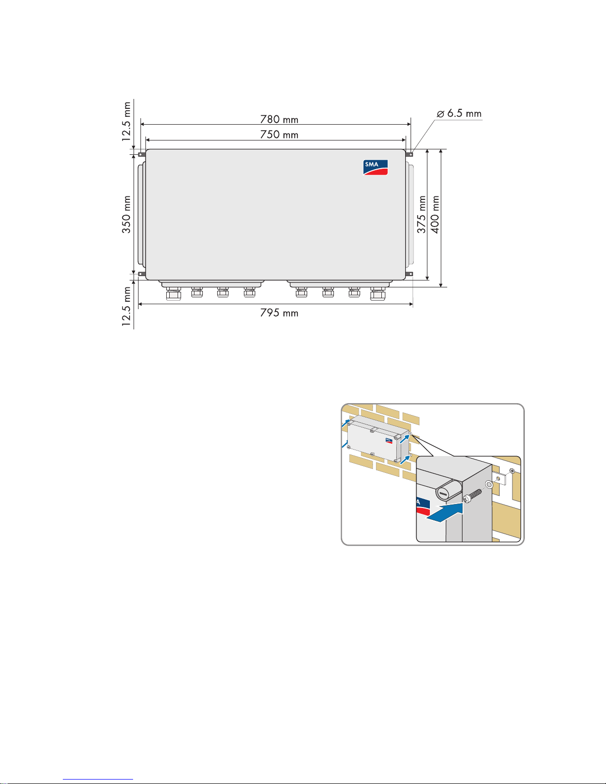
The following graphic shows the dimensions of the Sunny String-Monitor without DC circuit breaker.
1. Mark the position of the drill holes.
2. Drill holes at the marked positions.
3. Insert floor anchors.
4. Fasten the Sunny String-Monitor to the wall or stand
using suitable screws and washers.
5. Make sure that the device is securely in place.
Page 20
5Electrical Connection SMA Solar Technology AG
20 SSM-TEN103132 Technical Description
5 Electrical Connection
5.1 Safety
%"/(&3
Risk of lethal electric shock if the DC cable connected to the PV array is touched. The PV
modules exposed to light have voltages present.
•Cover the PV modules.
• Follow all safety instructions of the module manufacturer.
• Remove the appropriate DC fuses in the Sunny Central, and, if present, the Sunny Main Box.
• Disconnect the Sunny Central.
/05*$&
Damage to the electronics due to moisture penetration.
• Installation work should be carried out only during favorable weather conditions.
Page 21
SMA Solar Technology AG 5Electrical Connection
Technical Description SSM-TEN103132 21
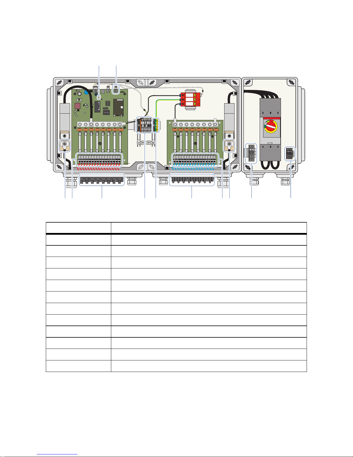
5.2 Overview of the Connection Area
Figure6:Terminals and plugs for connections
Position Description
A Jumper for data cable termination
BSignal contact for the anti-theft protection
C Terminals for the connection of the feedback signal contact
*
*
optional
D Terminals for the connection of the shunt release drive
E Bolt clamp to connect the DC main cable, - pole
F Spring-type terminals for the string connections, - pole
**
**
if connecting the strings directly
G Plug for the connection of the strings, - pole
H Terminals for the ground connection
I Terminals for the connection of the data cable and voltage supply
K Plug for the connection of the strings, + pole
L Spring-type terminals for the string connections, + pole**
M Bolt clamp to connect the DC main cable, + pole
A
EFGHIM
1 2
3 4 5 6
L+
L+
L
K
DC
B
Page 22

5Electrical Connection SMA Solar Technology AG
22 SSM-TEN103132 Technical Description
Figure7:Cable glands for direct connection of the PV strings to the disconnect terminals
Position Description
A Cable gland for connection of the DC main cable, + pole
B Cable glands for the string connections, + pole
C Cable glands for the ground connection
DVent plug
E Cable glands for the communications connection
F Cable glands for the string connections, - pole
G Cable gland for connection of the DC main cable, - pole
H Cable gland for the connection of the remote control
*
*
optional
I Cable gland for the connection of the feedback signal contact
*
Page 23

SMA Solar Technology AG 5Electrical Connection
Technical Description SSM-TEN103132 23
Figure8:Operating status LEDs
5.3 Closing and Opening the Sunny String-Monitor
Opening the Sunny String-Monitor
1. Turn all screw plugs 1/4 counterclockwise with a
screwdriver. Push lightly while doing this.
2. Remove the cover.
LED Function
LED 1, green Digital input, optional for anti-theft protection
LED 2, green Overvoltage protector
LED 3, orange Data transfer
LED 4, red Failure of the control board
L-
1 1 2 2 3 3 4 4 5 5 6 6 7 7 8 8
L+
1 2
1 1 2 2 3 3 4 4 5 5 6 6 7 7 8 8
L-
L+
12 3 4 5 6
Z9-X9
1234
Page 24

5Electrical Connection SMA Solar Technology AG
24 SSM-TEN103132 Technical Description
Closing the Sunny String-Monitor.
1. Replace the cover
2. Turn all screw plugs 1/4 clockwise with a
screwdriver. Push lightly while doing this.
3. Ensure that the cover is correctly in place.
5.4 Connecting the PV strings
5.4.1 Connect the PV Strings to the Spring Clamp Terminals
1. For each cable feed-through, remove filter plugs from the cable glands.
2. Guide the string cables through the cable gland into the enclosure interior. Make sure polarity
is correct when doing this.
3. Cut the insulated conductors to length and strip 12 mm off the insulation.
4. Connect the insulated conductors to the string-type terminals. Make sure polarity is correct when
doing this.
5. Tighten the cable glands.
5.4.2 Connect the PV Strings to the SUNCLIX DC Plug Connectors
Requirements:
☐ All cables of the PV modules are equipped with the SUNCLIX plug connectors included in
delivery.
Procedure:
• Assemble the SUNCLIX DC plug connectors
• Connect the SUNCLIX DC plug connectors to the Sunny String-Monitor
Page 25

SMA Solar Technology AG 5Electrical Connection
Technical Description SSM-TEN103132 25
Assemble the SUNCLIX DC plug connectors
1. Cut the insulated conductors to length and strip 12 mm off the insulation.
2. Insert the stripped cables into the plug connector
as far as they will go. Ensure the correctness of the
polarity assignment and of the type of plug.
3. Push the clamping bracket downward.
☑ The clamping bracket snaps audibly into place.
☑ The stranded wire can be seen inside the
clamping bracket chamber:
✖ Is the stranded wire not visible in the chamber?
The stranded wire is not correctly in place.
• Remove the clamping bracket with a
screwdriver. To do this insert the screwdriver
into the clamping bracket and pry it out.
• Remove the insulated conductor and start
again from step 2.
4. Push the threaded joint towards the thread and
screw into place.
Page 26

5Electrical Connection SMA Solar Technology AG
26 SSM-TEN103132 Technical Description
Connect the SUNCLIX DC plug connectors to the Sunny String-Monitor
1. Remove all transport plugs from all DC plug connectors.
2. Connect the assembled DC plug connectors.
3. Insert the sealing plugs provided into the DC plug
connectors that are not needed. This way you seal
the DC plug connectors.
4. Insert the DC plug connectors with sealing plugs in the remaining DC inputs on the Sunny StringMonitor. This way you seal the Sunny String-Monitor.
5.4.3 Connect the PV Strings to the Tyco, MC3 and MC4 Plugs
1. Remove the sealing plugs from the plugs.
2. Connect the DC plug connectors.
5.5 Connecting the DC Main Cable
Sealing plug
The sealing plugs included in the delivery are meant only for the DC plug connectors.
• Do not insert the sealing plugs into the DC inputs on the Sunny String-Monitor.
/05*$&
Damage to the electronics due to wrong cable installation.
In order for the Sunny String-Monitor and Sunny Central to work properly, EMC guidelines must be
observed.
• Lay the DC main cable and the data cable separately and at a distance greater than 400 mm
from one another.
8"3/*/(
Fire hazard due to faulty connections and rusted contact surfaces.
• Use special Al/Cu terminal lugs to connect an aluminum cable to the bolt clamp's copper bolt.
• Before connecting the cables clean the contact surfaces.
• Do not touch the contact surfaces after cleaning.
Page 27

SMA Solar Technology AG 5Electrical Connection
Technical Description SSM-TEN103132 27
Procedure:
• Clean the contact surfaces of the terminal lugs
• Connecting the DC Main Cable
Clean the contact surfaces of the terminal lugs
1. Clean the contact surfaces with a clean cloth and ethanol cleaner.
2. Clean the contact surfaces with an abrasive fabric. Avoid damage to the coated contact
surfaces.
3. If the contact surfaces have a light metallic shine, then they are sufficiently cleaned.
4. Remove metal dust with a clean cloth and ethanol cleaner.
Connecting the DC Main Cable
1. Remove the filler-plugs from the cable glands.
2. Guide the DC main cable through the cable glands into the enclosure interior. Make sure
polarity is correct when doing this.
3. Fit the DC main cable with terminal lugs.
4. Connect the DC main cable to the bolt clamp.
Observe the correct polarity when doing this and
tighten the bolt clamp with 20 Nm torque.
5. Make sure the DC main cable sits firmly in place.
6. Tighten the cable glands.
5.6 Connecting to Ground
To guarantee the functionality of the integrated overvoltage protectors, they must be connected to an
external ground.
1. Remove the filler-plugs from the cable gland.
2. Guide the ground cable through the cable gland into the enclosure interior.
3. Strip the ground cable 14 mm.
4. Connect the ground cable to the ground terminal. Tighten the ground terminal to 3.5 Nm torque.
5. Tighten the cable gland.
6. Ground the grounding cable in the vicinity of the Sunny String-Monitor, for example, with a
ground rod.
Page 28

5Electrical Connection SMA Solar Technology AG
28 SSM-TEN103132 Technical Description
5.7 Connecting the Data Cable
5.7.1 Data Cable Properties
The data cable of the RS485 communication and the power supply connects the Sunny StringMonitor to the Sunny Central.
• Use a shared cable of type Li2YCYv (TP) 4 x 2 x 0.5 mm for the data cable of the RS 485
communication and the +55 V
DC
voltage supply.
• Observe the component identification sign (CIS) inside the device.
5.7.2 Connect the Data Cable Shield Contact
1. Remove the filler-plugs from the cable glands.
2. Guide the data cables through the cable glands into the enclosure interior.
3. Remove the data cable cover.
4. Fit the cable shield on the shield rails. The shield rails are underneath the connection terminals.
5. Set down the shield clamps until they click into place,
and tighten by hand.
6. Tighten the cable glands.
5.7.3 Connecting the Data Cable in the Sunny String-Monitor
/05*$&
Damage to the electronics due to wrong cable installation.
In order for the Sunny String-Monitor and Sunny Central to work properly, EMC guidelines must be
observed.
• Lay the DC main cable and the data cable separately and at a distance greater than 400 mm
from one another.
• Lay the data cable shield on both sides - in the Sunny Central and in the Sunny String-Monitor.
Limited number of Piggy-Backs for data processing per hub
• Connect a maximum of 10 Piggy-Backs for data processing per hub.
Page 29

SMA Solar Technology AG 5Electrical Connection
Technical Description SSM-TEN103132 29
Figure9:Connection of the data cables between the Sunny String-Monitor
1. Strip 8 mm off each insulated conductor in the data cable.
2. Remove the label from the communication terminal strip.
3. Connect the insulated conductors of data cable to the connection terminals. Observe the
terminal allocation.
4. Carry the wiring between the individual Sunny String-Monitors SSM in a bus. Observe the
terminal allocation of the data cable.
Parallel Connection of the Data Cables
If several Sunny String-Monitor are being used, connect them in parallel. This way there will
be an incoming and an outgoing data cable at every Sunny String-Monitor. The final
Sunny String-Monitor is an exception. There will be only an incoming data cable connected
there.
L-
1 1 2 2 3 3 4 4 5 5 6 6 7 7 8 8
L+
12
1 1 2 2 3 3 4 4 5 5 6 6 7 7 8 8
L-
L+
12 34 5 6
Z9-X9
L-
1 1 2 2 3 3 4 4 5 5 6 6 7 7 8 8
L+
12
1 1 2 2 3 3 4 4 5 5 6 6 7 7 8 8
L-
L+
12 34 5 6
Z9-X9
L-
1 1 2 2 3 3 4 4 5 5 6 6 7 7 8 8
L+
12
1 1 2 2 3 3 4 4 5 5 6 6 7 7 8 8
L-
L+
12 34 5 6
Z9-X9
1 2 3 4 5 6
1 2 3 4 5 6
Page 30

5Electrical Connection SMA Solar Technology AG
30 SSM-TEN103132 Technical Description
5.7.4 Connecting the Data Cable in the Sunny Central
On all Sunny Central inverters the connection of the data cable from the Sunny String-Monitor is done
at the hub. Exception: in the case of the CP series Sunny Central, the Sunny String-Monitor is
connected to its own terminal strip. You will find detailed information in the installation manual of the
CP series Sunny Central.
Figure10:Connection of the data cables between the Sunny Central and the Sunny String-Monitor
1. Insert the data cable into the Sunny Central The Sunny Central installation manual contains
instructions for the cable insertion.
2. Strip 8 mm off each insulated conductor in the data cable.
3. Remove the sticker on the connection area of the hub.
4. Connect the insulated conductors of the data cable to the connection terminals on the hub in
accordance with the Sunny Central circuit diagram. Observe the terminal allocation of the data
cable.
L-
1 1 2 2 3 3 4 4 5 5 6 6 7 7 8 8
L+
12
1 1 2 2 3 3 4 4 5 5 6 6 7 7 8 8
L-
L+
123 45 6
Z9-X9
1 2 3 4 5 6
Z9-X9
55V
SSM
Power
SCC
Data-
Data+
GND
GND
+55V
+55V
RS485
OUT
RS485
IN
S
tring M
o
n
ito
r
P
o
w
e
r
S
u
p
p
l
y
U
n
i
t
/
H
u
b
F
U
S
E
L
L
N
N
N
C
P
E
P
E
A
C
+
5
5
V
S
S
M
P
o
w
e
r
S
C
C
D
a
t
a
D
a
t
a
+
G
N
D
G
N
D
+
5
5
V
+
5
5
V
R
S
4
8
5
O
U
T
R
S
4
8
5
I
N
U
1
-
A
6
Page 31

SMA Solar Technology AG 5Electrical Connection
Technical Description SSM-TEN103132 31
5.7.5 Terminating the Data Cable
In each case, the last Sunny String-Monitor of a string and the last hub in the Sunny Central are
terminated.
The Sunny String-Monitor are not terminated on delivery, therefore they can be configured freely onsite. The hub in the Sunny Central is terminated on delivery.
Figure11:Termination of the data cable (example)
Requirements:
☐ All Sunny String-Monitor on a string are connected to the RS485 bus (see chapter
5.7.3”Connecting the Data Cable in the Sunny String-Monitor”,page28 and chapter
5.7.4”Connecting the Data Cable in the Sunny Central”,page30).
Page 32

5Electrical Connection SMA Solar Technology AG
32 SSM-TEN103132 Technical Description
1. Plug the jumper on the measuring board in the last
Sunny Central of each string.
2. Remove the remaining jumpers from the measuring
boards of the remaining Sunny String-Monitor.
3. Make sure that the terminating resistor at the hub in the Sunny Central is plugged into the "485
Out" RJ45 socket.
5.8 Connecting the Remote Tripping for the DC Circuit Breaker
5.8.1 Dimensioning the Connection Cable for the Operating
Current Release
Depending on the order, the Sunny String-Monitor includes a DC circuit breaker with a remote trigger.
In this case, the DC circuit breaker is equipped with a shunt release. Depending on the order, the
Sunny String-Monitor includes as a shunt release an operating current release or an undervoltage
release.
By means of the shunt release it is possible to disconnect the PV array from the inverter through the
DC switch.
The shunt release is used to switch off the DC switch in an electrically-controlled fashion. Action of the
operating current release is guaranteed at a voltage between 70 % and 110 % of the nominal
voltage of the operating current release UN. If there is voltage present at the operating current
release, the DC switch is triggered. This is controlled via a normally make contact. In the event of wire
breakage, loose connection, undervoltage or loss of voltage supply, the function of the operating
current release is not guaranteed. We recommend the use of an uninterrupted voltage supply. The
activation time for secure tripping of the operating current release is at least 3 seconds.
1. Determine the number of DC switches.
2. Determine the greatest distance between the Sunny String-Monitor or voltage supply and the
first Sunny String-Monitor.
3. Determine the minimum cable cross section according to figure 12.
1
1
2
2
3
3
4
4
5
5
6
6
7
7
8
8
L+
1 2
1
1
2
2
3
3
4
4
5
5
6
6
7
7
8
8
L-
L+
1
2
3
4
5
6
Z9-X9
Page 33

SMA Solar Technology AG 5Electrical Connection
Technical Description SSM-TEN103132 33
Figure12:Relationship between cable length, number of Sunny String-Monitor connected and cable crosssection.
Example: Dimensioning a Connection Cable
In order to achieve secure tripping, the minimum cross-section of the connection cable must be
determined. The cable cross-section to be selected depends on the number of connected Sunny
String-Monitor, the cable length to the voltage supply and the cable lengths between the connected
Sunny String-Monitor.
In a PV plant there are 20 DC switches. The greatest distance between the Sunny String-Monitor or
the voltage supply is 150 m.
According to figure 12 the cable cross section must be at least 4 mm
2
.
Page 34

5Electrical Connection SMA Solar Technology AG
34 SSM-TEN103132 Technical Description
5.8.2 Dimension the Connection Cable for the Undervoltage
Release
Depending on the order, the Sunny String-Monitor includes a DC circuit breaker with a remote trigger.
In this case, the DC circuit breaker is equipped with a shunt release. Depending on the order, the
Sunny String-Monitor includes as a shunt release an operating current release or an undervoltage
release.
By means of the shunt release it is possible to disconnect the PV array from the inverter through the
DC switch.
The undervoltage release is used to switch off the DC switch in an electrically-controlled fashion. The
DC switch is triggered when there is no voltage at the undervoltage release, or if the voltage falls
below 85 % of the release nominal voltage UN. After tripping, the circuit breaker can be connected
again after the voltage rises above 85 % of the undervoltage release nominal voltage UN. The DC
switch can be switched on manually only if there is voltage at the undervoltage release. In order to
avoid an inadvertent tripping, an uninterrupted power supply is recommended. The undervoltage
release is designed for continual operation. Activation takes place via a normally break contact. The
undervoltage release is the suitable tripping element for secure shutdowns or locks, for example, an
emergency stop, because there is always a disconnection if there is a fault. The minimum interruption
time for secure tripping of the undervoltage release is 1 second.
☐ Cable cross section: at least 2.5 mm
2
.
☐ Total cable length: 1 000 m maximum.
Page 35

SMA Solar Technology AG 5Electrical Connection
Technical Description SSM-TEN103132 35
5.8.3 Connect Shunt Release
Depending on the order, the Sunny String-Monitor includes a DC circuit breaker with a remote trigger.
In this case the DC circuit breaker is equipped with a shunt release and a feedback contact.
By means of the shunt release it is possible to disconnect the PV array from the inverter through the
DC switch.
1. Remove the filler-plugs from the cable gland.
2. Guide the connection cable through the cable gland into the enclosure interior.
3. Strip the connection cable 14 mm.
4. Connect the connection cable to the terminal strip.
5. Tighten the cable gland.
5.8.4 Connecting the Feedback Contact
Depending on the order, the Sunny String-Monitor includes a DC circuit breaker with a remote trigger.
In this case the DC circuit breaker is equipped with a shunt release and a feedback contact.
The switch status can be displayed via the feedback contact, for example by the connection of an
indicator lamp. The feedback contact is a toggle switch and can be used as an NC or as an NO
contact.
1. Remove the filler-plugs from the cable gland.
2. Guide the connection cable through the cable gland into the enclosure interior.
3. Strip the connection cable 11 mm.
4. Connect the connection cable to the terminal strip.
5. Tighten the cable gland.
/05*$&
Destruction of the operating current release due to faulty cable dimensioning.
A cable cross section which is too small can lead to strong overheating of the operating current
release. Strong overheating can destroy the operating current release.
• Observe the indications regarding cable dimensioning (see chapter 5.8.1”Dimensioning the
Connection Cable for the Operating Current Release”,page32).
Cable protection
• Furnish the connection cable of the remote trigger with a suitable cable protector.
Page 36

5Electrical Connection SMA Solar Technology AG
36 SSM-TEN103132 Technical Description
5.9 Install Anti-Theft Protection
The Sunny String-Monitor allows activation of anti-theft protection for the PV modules. Here, the
contacts at the PV modules are connected to form a signal chain. Upon interruption of the signal chain,
an anti-theft warning appears in the Sunny Central Control display, and an e-mail message is sent
immediately.
Installation of the cable gland and wiring is carried out by the customer.
1. Implement the contacts at the PV modules as NC contacts and connect to form a signal chain.
2. Integrate the signaling contact for the anti-theft protection on the measuring board into the
monitoring circuit (see chapter 5.2”Overview of the Connection Area”,page21).
5.10 Identification of the Piggy-Back for Data Processing
The serial number serves to identify the Piggy-Backs for data processing. The position of the serial
number depends on the production version of the Piggy-Back for data processing.
All serial numbers of the Piggy-Backs for data processing of the measuring circuit boards in all Sunny
String-Monitor must be written down in the commissioning report. You need the serial numbers for the
settings on the Sunny Central Control and for grouping the individual measuring boards.
Figure13:Possible position of the serial number
Requirements:
☐ The Sunny String-Monitor is activated (see chapter 6.3”Disconnecting the Sunny String-
Monitor”,page39).
• Identify the serial numbers and write them down.
Maximum Loop Resistance
The signal chain may not exceed a loop resistance of 300 Ohms so as to prevent the
alarm contact from being overloaded.
Position Description
A Serial number above in the middle line
B Serial number in the middle
C Serial number below
L-
1 1 2 2 3 3 4 4 5 5 6 6 7 7 8 8
L+
12
1 1 2 2 3 3 4 4 5 5 6 6 7 7 8 8
L-
L+
12 3 45 6
Z9-X9
FA:2349566
SER: 20326
SMU8HV-DVPB
A3
Page 37

SMA Solar Technology AG 6Commissioning
Technical Description SSM-TEN103132 37
6Commissioning
6.1 Commissioning the Sunny String-Monitor
The commissioning report must be filled out during commissioning. The commissioning report form is
enclosed with the Sunny Central.
Requirements:
☐ The DC circuit breaker is disconnected.
☐ The DC main cables are connected to the inverter or DC distribution box and are activated.
There is no reverse voltage from the inverter.
☐ All connections are made according to this manual (see chapter 5”Electrical
Connection”,page20).
Check the following points and document them in the commissioning report:
• Polarity of the DC voltages at the string inputs and at the DC main cables.
• All strings have similar voltage values.
• Check for the absence of ground faults on the strings and the DC main cables.
• Inspect the screw connections visually.
• Fuses correspond to the system design.
•The terminal allocation of the data cable is correct.
• All covers have been replaced.
Page 38

6Commissioning SMA Solar Technology AG
38 SSM-TEN103132 Technical Description
6.2 Switching On the Sunny String-Monitor
1. Remove the plexiglass covers.
2. Insert the string fuses.
3. Replace the plexiglass covers.
4. Activate the DC circuit breaker.
☑ After the inverter has been commissioned, on the control circuit board LEDs 1 and 2 glow green
and LED 3 glows orange periodically.
Anti-theft protection, overvoltage protector are intact, data cable and control circuit board
are OK.
✖ After the inverter has been commissioned, does LED 1 or 2 not light up, is LED 3 off for more
than 5 minutes, does LED 4 light up red?
• see section 9”Troubleshooting”,page59
%"/(&3
Risk of lethal electric shock.
• Work on the Sunny String-Monitor may only be performed after switching off the power to the
unit in accordance with the regulations applicable to the installation site.
– Disconnect
– Ensure that the device cannot be reconnected
– Ensure that no voltage or current is present
– Cover or isolate adjacent live elements
Page 39

SMA Solar Technology AG 6Commissioning
Technical Description SSM-TEN103132 39
6.3 Disconnecting the Sunny String-Monitor
1. If there is a DC circuit breaker on the Sunny String-Monitor, disconnect it. This way the Sunny
String-Monitor is free of current and voltage.
2. If there is no DC circuit breaker, disconnect the Sunny Central (see the installation manual for
the Sunny Central).
3. Remove the fuses in the Sunny Central.
4. If there are no fuses in the Sunny Central, remove the fuses in the DC main distributor (e.g.,
Sunny Main Box).
5. Cover the modules.
6. Disconnect all solar plugs.
%"/(&3
Risk of lethal electric shock.
• Observe the following safety rules when disconnecting:
– Disconnect
– Ensure that the device cannot be reconnected
– Ensure that no voltage or current is present
– Cover or isolate adjacent live elements
%"/(&3
Risk of lethal electric shock. The discharge time of the capacitors is longer than 5 minutes.
• After disconnection, wait until the capacitors have discharged.
8"3/*/(
Danger of burns by touching hot components.
• Wear safety gloves during all work on the device.
Page 40

6Commissioning SMA Solar Technology AG
40 SSM-TEN103132 Technical Description
6.4 Reconnect the DC Circuit Breaker after Tripping
If the PV array was disconnected from the inverter by means of the remote trip in the Sunny StringMonitor, you must switch on the DC circuit breaker again.
1. Search for the cause of the tripping, and remove it.
2. Open the Sunny String-Monitor (see chapter 5.3”Closing and Opening the Sunny StringMonitor”,page23).
3. Switch the DC circuit breaker manually from the triggered position to the off position.
4. Switch the DC circuit breaker manually from the off position to the on position.
✖ The DC circuit breaker cannot be switched on?
The shunt release is activated.
• If the shunt release is an operating current release, make sure there is no current at the
operating current release.
• If the shunt release is an undervoltage release, make sure that there is a voltage at the
undervoltage release.
5. Close the Sunny String-Monitor (see chapter 5.3”Closing and Opening the Sunny StringMonitor”,page23).
Page 41

SMA Solar Technology AG 7Configure Sunny String-Monitor
Technical Description SSM-TEN103132 41
7 Configure Sunny String-Monitor
7.1 Configure the Sunny String-Monitor via Sunny Central Control
7.1.1 Organizing the Configuration
The Sunny Central Control operation is described in the Sunny Central user manual.
Password Protection
The installer password must be entered in order to configure the Sunny Central String-Monitor
in the Sunny Central Control. Please refer to the Sunny Central user manual for detailed
information.
Procedure See
1 Check the serial interface settings at the Sunny Central
Control
section 7.1.2
2 If Sunny String-Monitor are to be detected for the first time:
Deleting detected Sunny String-Monitor
section 7.1.5
3 Detect Sunny String-Monitor section 7.1.3
4 Setting the device address section 7.1.4
Page 42

7Configure Sunny String-Monitor SMA Solar Technology AG
42 SSM-TEN103132 Technical Description
7.1.2 Check the Serial Interface Settings at the Sunny Central
Control
Parameters of the COM1 interface are predefined and factory-set.
• Medium RS485
• Baudrate 19200 Baud
•SMA-Net protocol
1. Select Device Set-up > Interfaces > Communication > COM1:SMUs.
☑ The interface parameters appear:
2. Make sure that the correct parameters are set.
☑ The parameters are set correctly.
✖ Are the parameters set incorrectly?
• Set the parameters for medium, baudrate and protocol correctly.
7.1.3 Detecting Sunny String-Monitor
1. Select Device Set-up > SMUs > Devices > Detection.
☑ The Sunny Central Control begins detection of new devices automatically.
2. Adopt the changes and save.
3. Check whether all the serial numbers of the Piggy-Backs for data processing are registered
correctly by the measurement circuit boards of the respective Sunny String-Monitor.
–Select Device Set-up > SMUs > Devices > Registration.
☑ The registered serial numbers match the actual serial numbers on the Piggy-Backs for data
processing.
✖ Not all indicated serial numbers are on the list?
• Start again with step 2.
✖ Are there any problems in detecting the Sunny String-Monitor?
• See Section .9”Troubleshooting”,page59
Page 43

SMA Solar Technology AG 7Configure Sunny String-Monitor
Technical Description SSM-TEN103132 43
7.1.4 Setting the Device Address
To identify the measuring circuit boards in the Sunny String-Monitor, each Piggy-Back for data
processing is assigned a number as "SSM identifier". This makes troubleshooting easier, for example,
in the event of a string failure, or deviating string currents. The "SSM Identifier" does not correspond
to the network address which is automatically assigned upon detection. The Sunny Central Control
supports up to 40 "SSM Identifiers".
1. Select Device Setup > SMUs > Devices > Parameters.
2. Select Sunny String-Monitor.
3. Select the device address SSM Identifier.
4. Assign the Sunny String-Monitor a number between 1 and 40.
5. Adopt all changes.
7.1.5 Deleting detected Sunny String-Monitor
1. Select Device Set-up > SMUs > Devices > Registration.
2. Select Sunny String-Monitor.
3. Select the ID submenu.
4. Set the ID number to 99.
5. Adopt all changes.
Page 44

7Configure Sunny String-Monitor SMA Solar Technology AG
44 SSM-TEN103132 Technical Description
7.2 Configure the Sunny String-Monitor with Sunny Data Control
7.2.1 Setting the Required Values
Sunny Data Control is a PC program by SMA Solar Technology AG with which you can store your
PV plant data in the long term and visualize it. Sunny Data Control can be downloaded at
www.SMA.de/en free of charge. Please refer to the Sunny Data Control user manual for detailed
information on its use.
If you install Sunny Data Control anew, or a current version of it, on your PC, default values are set
for this new version. For the communication with Sunny Central Control, the following values are
needed:
Password Protection
In order to change certain parameters, entering the installer password is required. For this,
contact the SMA Serviceline. Further information on password protection can be found in the
Sunny Data Control user manual.
Feature Default Value Value for Sunny Central Control
Channel request 10 s 200 s
Storage Time Refresh 10 s 200 s
First detection 5 s 10 s
Further detection 7 s 10 s
Page 45

SMA Solar Technology AG 7Configure Sunny String-Monitor
Technical Description SSM-TEN103132 45
Figure14:Window for setting of required values
1. Choose Options > Settings
☑The "Settings" window opens.
2. In the tree structure, select "Timing".
3. In the area "Properties", select Meanval Request > Channel Request
4. In the box "Value", enter 200.
5. In the area "Properties", select Meanval Request > Storage Time Request
6. In the box "Value", enter 200.
7. In the area "Properties", select Device Detection > Detection Find First
8. In the box "Value", enter 10.
9. In the area "Properties", select Device Detection > Detection Find Next.
10. In the box "Value", enter 10.
11. Select [OK].
Position Description
A Tree structure
B"Properties" area
C Parameters to be set
D"Value" box for entering values
E[OK] button to save the values
Page 46

7Configure Sunny String-Monitor SMA Solar Technology AG
46 SSM-TEN103132 Technical Description
7.2.2 Configuring Sunny String-Monitor
Figure15:Buttons and input windows for configuring the Sunny String-Monitor
Requirements:
☐ Piggy-Backs for data processing are detected in Sunny Central Control (see chapter
7.1.3”Detecting Sunny String-Monitor”,page42).
Position Description
A[Search] button to detect devices
B Labeling of the Sunny String-Monitor with the serial number of the Piggy-
Back for data processing in the system tree
C"Parameters" tab
D"Parameters" area
E"Channel value" area to enter or select values
F[Set] button to save the values
Page 47

SMA Solar Technology AG 7Configure Sunny String-Monitor
Technical Description SSM-TEN103132 47
1. Select [Search].
☑ Sunny Data Control starts detecting new devices.
2. Compare the detected serial numbers in the system tree with the actual serial numbers on the
Piggy-Back for data processing.
☑ The compared serial numbers are identical.
✖ The compared serial numbers are not identical?
• Start again with step 2.
✖ Are there any problems in detecting the Sunny Central String-Monitors?
• See Section .9”Troubleshooting”,page59
3. Setting of the Device Address for each Sunny Central String-Monitor.
– Sunny String-Monitor in the system tree.
–In the "Parameters" area, click on SSM Identifier.
– In the area "Channel value" enter a value between 1 and 40.
– To save, select [Set].
Page 48

8Function of the String Current Monitoring SMA Solar Technology AG
48 SSM-TEN103132 Technical Description
8 Function of the String Current Monitoring
8.1 Requirements for Activating the String Current Monitoring
☐ The DC power of the PV array exceeds 5 % of the AC nominal power of the Sunny Central.
P
DC
> 0.05 P
AC,Nom
☐ The string current mean value of the individual groups is equal/greater than 0.5 A.
I
String
≥ 0.5A
8.2 Functionality of the String Current Monitoring
The string current monitoring measures the string currents and compares them to a mean value. If a
string current exceeds or falls short of the mean value by the set tolerance, the Sunny Central Control
displays warning 380 "SMU". The information below describes how the mean value is established,
what intervals are used to transmit data, and how the string current monitoring is configured.
Polling intervals
The Sunny String-Monitor continually measures the string currents and saves them in cycles.
SunnyCentralControl reads these values every 5 minutes.
Group strings
Individual strings can be grouped in up to 4 groups in Sunny Central Control. Sunny Central Control
creates mean values for the groups 1, 2, and 3. These mean values are then used as reference values
for string current monitoring. The strings that are not monitored are grouped in group 0.
Tripping Time
The tripping time is the time span between the occurrence of a fault and the fault indication. The
tripping time is set to 180 minutes as default. The tripping time can be set between 2 and
1 440 minutes for each group.
Tolerance
The tolerance indicates how much the string current may deviate from the mean value. When the string
current is outside the tolerance limits, Sunny Central Control detects the deviation. The tolerance can
be set between 10 % and 100 %.
Value Description
P
DC
PV generator output
P
AC, nom
AC nominal power of the Sunny Central
Value Description
I
String
String current of the individual groups
Page 49

SMA Solar Technology AG 8Function of the String Current Monitoring
Technical Description SSM-TEN103132 49
Error sum
The error sum is a measure of the sensitivity of the string current monitoring. It can be parameterized
via the tripping time and tolerance, and is described by the following formula:
Comparison
Every 5 minutes, the Sunny Central Control compares the string current with the reference value for
the group. When the string current is outside the tolerance limits, Sunny Central Control records the
deviation. When the deviation exceeds the error sum, the Sunny Central Control displays the "SMU"
warning.
If the deviation is smaller than the error sum, the Sunny Central Control records the deviation. If a
deviation between the string current and the reference value persists, the deviations are recorded. As
soon as the deviations exceed the error sum, the Sunny Central Control displays the "SMU" warning.
The submenu "SMUs…Failure" shows which Sunny String-Monitor and which measuring channels
deviate too much from the group mean value. Upon confirmation at the Sunny Central Control, the
error sum is reset, and the warning disappears from the display.
With the flexible parameterization, the Sunny String-Monitor can detect the complete failure of a
string within one polling interval. Slightly elevated string currents are reliably detected in several
polling intervals and distinguished from typical current fluctuations of the PV array.
Page 50

8Function of the String Current Monitoring SMA Solar Technology AG
50 SSM-TEN103132 Technical Description
Example:
It is assumed that at t0 the mean value of a group is 5 A. All string currents are now compared to
this mean value. If no string current lies outside the set tolerance of (e. g.) 10 %, totaling is not
performed. The tolerance in this example ranges from 4.5 A to 5.5 A.
If, however, a string shows a string current of 6 A, then the difference between the actual string
current of 6 A and the tolerance limit of 5.5 A is added to the total. The difference is thus 0.5 A,
which is a deviation of 10 % from the mean value. This difference of 10 % is now added to the total
until the error sum is reached. Assuming that the string current lies at 6 A for a longer period of time,
and the tripping time is set to 10 minutes, then the error sum can be calculated as follows:
Page 51

SMA Solar Technology AG 8Function of the String Current Monitoring
Technical Description SSM-TEN103132 51
On the basis of this example and the calculation formula, the sensitivity of the string current monitoring
can now be set by using the two parameters tripping time and tolerance. The parameters for String
Current Monitoring can be set via Sunny Central Control or the Sunny Data Control software.
8.3 Setting the Parameters Using Sunny Central Control
8.3.1 Setting the Number of Strings per Measuring Channel
The number of strings per channel is freely selectable for the 8 measuring channels. The default setting
is "1". The maximum number of strings per channel is limited to 4.
The optimal allocation for a measuring channel is intended to be 2 strings, nevertheless one can,
depending on the system design, connect more strings in parallel outside the Sunny String-Monitor
and append them to a measuring channel (see chapter 2.2”Parallel Connection of
Strings”,page10).
TIP:
In the submenu No. of Str. All you can assign all channels of the Sunny String-Monitor to a string
number of 1 to 4. This avoids having to set the number of strings for each of the individual channels,
since this is automatically set for all the individual channels.
Based on the calculation in this example, a value of 20 % is calculated for the error sum. In this
manner, the current difference of 0.5 A, which equates to a deviation of 10 % of the mean value, is
added to the total for each query interval of 5 minutes, until the error sum of 20 % is reached. In this
example, the error value is reached after two polling intervals. The Sunny Central Control displays
the warning "SMU".
If a string fails, the current difference in the above example is 4.5 A, which equates to a deviation
of 90 % from the mean value. If the settings in the above example remain the same, i.e. tolerance
at 10 % and tripping time at 10 minutes, the error sum of 20 % is already reached after the first
polling interval of 5 minutes. The Sunny Central Control now displays the warning "SMU".
No strings in a measuring channel
• If there are no strings connected to a measuring channel, assign this channel to the
0 group (see chapter 8.3.2”Setting the Groups”,page52).
Page 52

8Function of the String Current Monitoring SMA Solar Technology AG
52 SSM-TEN103132 Technical Description
1. Select Device Setup > SMUs > Devices > Parameters.
2. Select Sunny String-Monitor.
3. In the submenu No. Of Strings or No. of Str. All set the number of strings connected per
measuring channel used.
8.3.2 Setting the Groups
With Sunny Central Control one can subdivide the individual measuring channels of the connected
measuring boards into 3 groups, to make it possible to compare only the measuring channels which
have the same properties. The groups are monitored independently of each other, and each
individual measuring channel can be allocated freely to any group. An individual group must include
at least 4 measuring channels.
TIP:
In the Group all chan. all the measuring channels of the measuring circuit board can be assigned
to a group.` This avoids having to allocate the individual measuring channels to a group as this then
occurs automatically for all the individual measuring channels.
If you wish not to include individual channels from the measuring board in the string current
monitoring, these should be assigned to the 0 group, since string monitoring is deactivated for this
group. This way, this measuring channel is not included in the average value calculation.
1. Select Device Setup > SMUs > Devices > Parameters.
2. Select Sunny String-Monitor.
3. In the Group channel or Group all chan. submenu, set the group numbers for the measuring
channels.
8.3.3 Setting the Tripping Time
Using the tripping time, you can set the sensitivity of the string current monitoring, since it is included
in the calculation of the error sum (see chapter 8.2”Functionality of the String Current
Monitoring”,page48).
1. Select Device Set-up > SMUs > Parameters.
2. In the Error report time submenu, set the value in minutes.
Page 53

SMA Solar Technology AG 8Function of the String Current Monitoring
Technical Description SSM-TEN103132 53
8.3.4 Setting the Tolerance
Using the tripping time, you can set the sensitivity of the string current monitoring, since it is included
in the calculation of the error sum (see chapter 8.2”Functionality of the String Current
Monitoring”,page48).
Since only a clear deviation of a measuring channel from a mean value is an indication of a faulty
string, whereas minor deviations can be considered normal, the tolerance value should be set
accordingly high.
1. Select "Device Set-up > SMUs > Parameters".
2. In the submenu Tolerance Grp, set the value per group.
8.3.5 Setting the Time Window
In order to filter out temporary effects (such as shadowing on an individual string, it is possible to
define a time window for every individual channel of the Sunny Central String-Monitor. For each time
window, the defined string will only be monitored starting at and until the respective times of day set.
TIP:
Under Monitoring On and Monitoring Off, one can set a specific time window for all measurement
channels of the Sunny String-Monitor for string current monitoring.
1. Select Device Set-up > SMUs > Devices > Parameters.
2. Select Sunny String-Monitor.
3. In the submenu under Monitoring On and Monitoring Off, set a specific time window per
measurement channel or for all measurement channels of the Sunny String-Monitor.
8.3.6 Setting overnight shutdown
Overnight shutdown in the Sunny Central is activated by default. Thus, the power supply to the
SunnyString-Monitors is deactivated in the Sunny Central as soon as the PV voltage has been under
250 V for one hour. The supply voltage is activated as soon as the PV voltage of 250 V is reached.
If overnight shutdown is deactivated, supply voltage to the Sunny String-Monitor remains on at night.
This means that theft protection can be activated and evaluated, see section 8.3.7”Setting Anti-Theft
Protection”,page53.
1. Select Device Set-up > SMUs > Parameters.
2. In the submenu SMU Overn. Shut, set the nighttime disconnection.
8.3.7 Setting Anti-Theft Protection
Anti-theft protection is deactivated by default in Sunny Central Control.
1. Select Device Set-up > SMUs > Parameters.
2. In the SMU Theft. submenu, set the anti-theft protection.
Page 54

8Function of the String Current Monitoring SMA Solar Technology AG
54 SSM-TEN103132 Technical Description
8.4 Setting the Parameters Using Sunny Data Control
8.4.1 Overview of the Program Window
Figure16:Buttons and input windows for parameterization of the Sunny String-Monitor
8.4.2 Setting the Number of Strings per Measuring Channel
1. Sunny String-Monitor in the system tree.
2. In the "Parameters" area, click No. Of Strings for the desired channel, or No. of Str. All.
3. In the area "Channel value", enter the number of PV strings per channel or for all channels.
4. To save, select [Set].
Position Description
A Second-tier designation of the device in the system tree
B Labeling of the Sunny String-Monitor with the serial number of the Piggy-
Back for data processing in the system tree
C"Parameters" tab
D"Parameters" area
E"Channel value" area to enter or select values
F[Set] button to save the values
Page 55

SMA Solar Technology AG 8Function of the String Current Monitoring
Technical Description SSM-TEN103132 55
8.4.3 Setting the groups
1. Sunny String-Monitor in the system tree.
2. In the "Parameters" area, click Group channel for the desired channel, or Group all chan.
3. In the area "Channel value", enter the number the group per channel of for all channels.
4. To save, select [Set].
8.4.4 Setting the Time Window
1. Sunny String-Monitor in the system tree.
2. In the area "Parameter", Monitoring (X) On for the desired channel or Monitoring. On for
the complete Sunny String-Monitor.
3. In the area "Channel value" enter the desired time of day starting at which the measuring
channel or the Sunny String-Monitor should be monitored.
4. To save, select [Set].
5. In the area "Parameter", Monitoring (X) Off for the desired channel or Monitoring Off for
the complete Sunny String-Monitor.
6. In the area "Channel value" enter the desired time of day up to which the measuring channel or
the Sunny String-Monitor should be monitored.
7. To save, select [Set].
8.4.5 Setting the Tripping Time
1. Click on the device label at the second level in the system tree.
2. In the area "Parameter", click on SMU_Error Report Time.
3. In the area "Channel value" enter the desired value in minutes.
4. To save, select [Set].
8.4.6 Setting the Tolerance
1. Click on the device label at the second level in the system tree.
2. In the "Parameter" area click SMU_Tolerance Grp for the desired group.
3. In the area "Channel value" enter the desired value in percent.
4. To save, select [Set].
Page 56

8Function of the String Current Monitoring SMA Solar Technology AG
56 SSM-TEN103132 Technical Description
8.4.7 Setting overnight shutdown
1. Click on the device label at the second level in the system tree.
2. In the area "Parameter", click on SMU_Overn. Shut.
3. In the area "Channel value", select On or Off from the drop-down list.
4. To save, select [Set].
8.4.8 Setting Anti-Theft Protection
1. Click on the device label at the second level in the system tree.
2. In the area "Parameter", click on SMU Theft.
3. In the area "Channel value", select On or Off from the drop-down list.
4. To save, select [Set].
8.5 Reading the Measurement Values in Sunny Central Control
8.5.1 Reading the Mean Values of the Groups
The mean values of the measuring channels are displayed for each group, and updated at 5 minute
intervals.
•Select Device Setup > SMUs > Measured Values and read the values.
8.5.2 Reading the Mean Values for the Individual Measurement
Channels
The mean values for the individual measurement channels are updated and displayed at 5-minute
intervals.
•Select Device Set-up > SMUs > Devices > Measured Values and read the values.
Page 57

SMA Solar Technology AG 8Function of the String Current Monitoring
Technical Description SSM-TEN103132 57
8.6 Reading the Measurement Values in Sunny Data Control
There are different presentation possibilities for the display of the measurement spot values in Sunny
Data Control. Detailed information on the settings for the device overview and other possibilities for
the presentation of values are described in the Sunny Data Control manual.
Figure17:Program window for reading spot values (example)
The Sunny String-Monitor window shows the average of the individual spot values.
The Sunny Central Control window shows the average values of the measurement values for each
group.
Position Description
A"Spot values" tab
B Sunny String-Monitor window with the list of spot values
C Sunny Central Control window with the list of spot values
Page 58

8Function of the String Current Monitoring SMA Solar Technology AG
58 SSM-TEN103132 Technical Description
8.7 Reading the Messages in Sunny Central Control
The individual meanings of the warnings and failures in the Sunny Central Control can be found in the
Sunny Central user manual.
Sunny Central Control resets messages which appear during a day automatically at 0:00 o'clock.
These messages can be read the next day in the event history. The individual error sums of the
measurement channels are reset at 0:00 o'clock.
8.7.1 Reading and Confirming Current Messages
1. Select Device Set-up > SMUs > Failure > Actual Failures.
2. To confirm the message, select the submenu SMU Error quit By doing this, you reset the error
sum.
8.7.2 Reading and Confirming the Event History
1. Select Device Set-up > SMUs > Failure > Hist. Failures.
2. To confirm the message, select the submenu SMU Error quit. By doing this, you reset the error
sum.
Page 59

SMA Solar Technology AG 9Troubleshooting
Technical Description SSM-TEN103132 59
9Troubleshooting
Symptom Cause Corrective measures
None of the LEDs is
glowing.
Problems with the power
supply.
• Check the +55 V power supply at
the connection area of the
respective Sunny String-Monitor.
LED 1 does not glow. Anti-theft protection is activated. • Check the wiring of the anti-theft
protection.
LED 2 does not glow. Overvoltage protector has
tripped.
• Replace a protection module in
the overvoltage protector.
LED 3 does not light up
for more than
5 minutes.
Problems with the data cable. • Check data cable between Sunny
Central and Sunny String-Monitor,
and between the individual Sunny
String-Monitor.
LED 4 glows red. Failure of the control board of
the string current monitoring.
• Contact the SMA Serviceline.
Problems in Detecting
the Sunny StringMonitor.
The Piggy-Back for data
processing is either missing or it
is not properly plugged.
The COM1 interface is not
configured properly.
The data cable in the last Sunny
String-Monitor of a string is not
terminated. Problems with
Sunny Central Control.
• Check that the RS485 Piggy-Back
is correctly mounted on the
measuring board.
• Check that the COM1 in the
Sunny Central Control is correctly
configured (see section
7.1.2”Check the Serial Interface
Settings at the Sunny Central
Control”,page42).
• Check termination in the last
Sunny String-Monitor. The jumper
on the last measuring board of a
string must be plugged (see
chapter 5.7.5”Terminating the
Data Cable”,page31).
• Check that the jumper has been
removed from the other measuring
boards in the individual Sunny
String-Monitor.
• Check that the bridge (PIN 7 – 9)
at the side of the Sunny Central
Control is mounted.
• Check that the COM1 at the
Sunny Central Control is equipped
with an RS485 Piggy-Back.
Page 60

10Technical data SMA Solar Technology AG
60 SSM-TEN103132 Technical Description
10 Technical data
Enclosure
Mechanical Data of the Enclosure without DC Circuit Breaker
Mechanical Data of the Enclosure with DC Circuit Breaker
General Data
Outdoor installation Only shaded
Wall mounting Yes
Material Glass-fiber reinforced plastic
UV resistance Yes
Combustion properties Self-extinguishing, halogen-free
Color Gray
Protective insulation Yes
Width x height x depth 795 mm x 400 mm x 230 mm
Weight 13 kg
Width x height x depth 1 050 mm x 400 mm x 230 mm
Weight 16 kg
DC circuit breaker
*
*
Direct drive
130 A
DC
Pollution degree
**
**
according to DIN EN 50178:1997
2
Page 61

SMA Solar Technology AG 10Technical data
Technical Description SSM-TEN103132 61
Input Parameters
DC Main Connection
Maximum permissible DC voltage U
DC, max
1 000 V
Maximum permissible DC voltage with a
25 A fuse
U
DC, max
950 V
Maximum permissible DC current I
DC,max
130 A
Number of measurement inputs 8
Maximum number of connections per
measurement input
*
*
optional
2
Possible string fuse sizes 10A/12A/ 16A/ 20A/ 25A
Maximum string current per measuring
channel with 10 A string fuse
**
**
Reduction factor 0.7
7A
Maximum string current per measuring
channel with 12 A string fuse
**
8.4 A
Maximum string current per measuring
channel with 16 A string fuse
**
11.2 A
Maximum string current per measuring
channel with 20 A string fuse
**
14 A
Maximum string current per measuring
channel with 25 A string fuse
***
***
Reduction factor 0.65
16.25 A
Measurement voltage supply U
DC
35 VDC… 55 V
DC
Type of terminal Bolt clamp
Torque 20 Nm
Bolt diameter M10
Maximum cable cross-section 150 mm
2
Sealing range 13 mm … 26 mm
Cable gland M40
Page 62

10Technical data SMA Solar Technology AG
62 SSM-TEN103132 Technical Description
String Connection to MC4 Plug Connector
String Connection to MC3 Plug Connector
String Connection to Plug Connector Tyco / Electronic
String connection to Plug Connector SUNCLIX
String Connection to Spring Clamp Terminals
Grounding Connection
Diameter 6 mm
2
Maximum rated current 30 A
Diameter 4 mm
2
Maximum rated current 20 A
Diameter 4 mm
2
Maximum rated current 20 A
Cable type PV1-F
Cable cross-section 2.5 mm
2
…6mm
2
Cable diameter 5 mm … 8 mm
Maximum rated current 40 A
Cable cross-section 0.2 mm2 … 6 mm
2
Multiple cable gland M32
Cable support sleeve 3 x 5 mm / 3 x 7 mm / 3 x 9 mm
Type of terminal Ground terminal
Maximum cable cross-section 35 mm
2
Cable gland M25
Sealing range 8 mm … 17 mm
Page 63

SMA Solar Technology AG 10Technical data
Technical Description SSM-TEN103132 63
Communication Connection
Remote Tripping with Shunt Release
Remote Tripping with Undervoltage Release
Feedback contact with Remote Tripping
Interfaces
Type of terminal 4-conductor through terminal
Cable cross-section 0.08 mm
2
…2.5mm
2
Cable gland M25
Sealing range 8 mm … 17 mm
Cable type 4x2x0.5mmLi2YCYv(TP)
Number of shield clamps 2
Maximum shield diameter 8 mm
Nominal voltage 220 V
AC
… 240 V
AC
Extended operating range ‒30 % … +10 %
Nominal frequency 50 Hz / 60 Hz
Power consumption 100 VA
Nominal voltage 220 V
AC
… 240 V
AC
Extended operating range ‒15 % … +10 %
Nominal frequency 50 Hz / 60 Hz
Power consumption 3 VA
Nominal voltage 250 V
AC/DC
Nominal current 5 AAC / 0.15 A
DC
Format 1 x toggle switch
Communication RS485
Transmission rate 19200 Baud
Monitored overvoltage protectors type II Yes
String current measurement Yes
Page 64

10Technical data SMA Solar Technology AG
64 SSM-TEN103132 Technical Description
Protection Rating and Ambient Conditions
Protection rating
*
*
Per DIN EN 60529
IP 54
Permissible ambient temperature –25 °C ... +40 °C
Rel. air humidity 15 % … 95 %
Maximum altitude above sea level, AMSL 1 000 m
Page 65

SMA Solar Technology AG 11Contact
Technical Description SSM-TEN103132 65
11 Contact
If you have technical problems with our products, please contact our Serviceline. We require the
following information in order to provide you with the necessary assistance:
• Type of the Sunny String-Monitor
• Serial number of the Sunny String-Monitor.
• Type and number of the PV modules connected
•Communication method
• Fault or warning number displayed
• Display message of the Sunny Central Control
SMA Solar Technology AG
Sonnenallee 1
34266 Niestetal, Germany
www.SMA.de
SMA Serviceline
Tel. +49 561 9522 299
Fax +49 561 9522 3299
E‑Mail: SunnyCentral.Service@SMA.de
Page 66

Page 67

SMA Solar Technology AG Legal Restrictions
Technical Description SSM-TEN103132 67
The information contained in this document is the property of SMA Solar Technology AG. Publishing its content, either partially or
in full, requires the written permission of SMA Solar Technology AG. Any internal company copying of the document for the
purposes of evaluating the product or its correct implementation is allowed and does not require permission.
Exclusion of liability
The general terms and conditions of delivery of SMA Solar Technology AG shall apply.
The content of these documents is continually checked and amended, where necessary. However, discrepancies cannot be
excluded. No guarantee is made for the completeness of these documents. The latest version is available online at www.SMA.de
or from the usual sales channels.
Guarantee or liability claims for damages of any kind are excluded if they are caused by one or more of the following:
• Damages during transportation
• Improper or inappropriate use of the product
• Operating the product in an unintended environment
• Operating the product whilst ignoring relevant, statutory safety regulations in the deployment location
• Ignoring safety warnings and instructions contained in all documents relevant to the product
• Operating the product under incorrect safety or protection conditions
• Altering the product or supplied software without authority
• The product malfunctions due to operating attached or neighboring devices beyond statutory limit values
• In case of unforeseen calamity or force majeure
The use of supplied software produced by SMA Solar Technology AG is subject to the following conditions:
• SMA Solar Technology AG rejects any liability for direct or indirect damages arising from the use of software developed by
SMA Solar Technology AG. This also applies to the provision or non-provision of support activities.
• Supplied software not developed by SMA Solar Technology AG is subject to the respective licensing and liability agreements
of the manufacturer.
SMA Factory Warranty
The current guarantee conditions come enclosed with your device. These are also available online at www.SMA.de and can be
downloaded or are available on paper from the usual sales channels if required.
Trademarks
All trademarks are recognized even if these are not marked separately. Missing designations do not mean that a product or brand
is not a registered trademark.
The Bluetooth
®
word mark and logos are registered trademarks owned by Bluetooth SIG, Inc. and any use of such marks by SMA
Solar Technology AG is under license.
SMA Solar Technology AG
Sonnenallee 1
34266 Niestetal
Germany
Tel. +49 561 9522-0
Fax +49 561 9522-100
www.SMA.de
E-Mail: info@SMA.de
© 2004 to 2010 SMA Solar Technology AG. All rights reserved
Page 68

XXX4."4PMBSDPN
4."4PMBS5FDIOPMPHZ
4."4PMBS5FDIOPMPHZ"(
XXX4."EF
4.""NFSJDB--$
XXX4.""NFSJDBDPN
4."5FDIOPMPHZ"VTUSBMJB1UZ-UE
XXX4.""VTUSBMJBDPNBV
4."#FOFMVY413-
XXX4."#FOFMVYDPN
4."#FJKJOH$PNNFSDJBM$P-UE
XXX4."$IJOBDPN
4."$[FDI3FQVCMJDTSP
XXX4."$[FDIDPN
4."'SBODF4"4
XXX4."'SBODFDPN
4.")FMMBT"&
XXX4.")FMMBTDPN
4."*C©SJDB5FDOPMPHB4PMBS4-
XXX4."*CFSJDBDPN
4."*UBMJB4SM
XXX4."*UBMJBDPN
4."5FDIOPMPHZ,PSFB$P-UE
XXX4.",PSFBDPN
 Loading...