

SMA Sunny Mini Central 9000TL, Sunny Mini Central 11000TL, Sunny Mini Central 10000TL Installation Manual
PV Inverter
SUNNY MINI CENTRAL 9000TL / 10000TL / 11000TL
Installation Guide
SMC9-11TL-IEN083620 | IME-SMCTL_9_10_11 | Version 2.0
EN


SMA Solar Technology AG Table of Contents
Table of Contents
1 Notes on this manual. . . . . . . . . . . . . . . . . . . . . . . . . . . . . . 7
1.1 Area of validity . . . . . . . . . . . . . . . . . . . . . . . . . . . . . . . . . . . . . . 7
1.2 Target group . . . . . . . . . . . . . . . . . . . . . . . . . . . . . . . . . . . . . . . . 7
1.3 Storage of Manuals . . . . . . . . . . . . . . . . . . . . . . . . . . . . . . . . . . 7
1.4 Additional Information . . . . . . . . . . . . . . . . . . . . . . . . . . . . . . . . 7
1.5 Symbols Used . . . . . . . . . . . . . . . . . . . . . . . . . . . . . . . . . . . . . . . 8
2 Security . . . . . . . . . . . . . . . . . . . . . . . . . . . . . . . . . . . . . . . . . 9
2.1 Appropriate Usage. . . . . . . . . . . . . . . . . . . . . . . . . . . . . . . . . . . 9
2.2 Safety Precautions. . . . . . . . . . . . . . . . . . . . . . . . . . . . . . . . . . . 10
3 Unpacking. . . . . . . . . . . . . . . . . . . . . . . . . . . . . . . . . . . . . . 11
3.1 Delivery Scope . . . . . . . . . . . . . . . . . . . . . . . . . . . . . . . . . . . . . 11
3.2 Check for Transport Damage . . . . . . . . . . . . . . . . . . . . . . . . . . 12
3.3 Identifying the Sunny Mini Central . . . . . . . . . . . . . . . . . . . . . . 12
4 Mounting. . . . . . . . . . . . . . . . . . . . . . . . . . . . . . . . . . . . . . . 13
4.1 Selection of the Mounting Location . . . . . . . . . . . . . . . . . . . . . 13
4.1.1 Dimensions and Weight . . . . . . . . . . . . . . . . . . . . . . . . . . . . . . . . . . . . . . . . 13
4.1.2 Ambient Conditions. . . . . . . . . . . . . . . . . . . . . . . . . . . . . . . . . . . . . . . . . . . . 14
4.1.3 Safety Clearances. . . . . . . . . . . . . . . . . . . . . . . . . . . . . . . . . . . . . . . . . . . . . 14
4.1.4 Position . . . . . . . . . . . . . . . . . . . . . . . . . . . . . . . . . . . . . . . . . . . . . . . . . . . . . 15
4.2 Mounting Instructions . . . . . . . . . . . . . . . . . . . . . . . . . . . . . . . . 16
5 Electrical Connection . . . . . . . . . . . . . . . . . . . . . . . . . . . . . 19
5.1 Overview of the Connection Area . . . . . . . . . . . . . . . . . . . . . . 19
5.1.1 View from Below. . . . . . . . . . . . . . . . . . . . . . . . . . . . . . . . . . . . . . . . . . . . . . 19
5.1.2 View from Inside . . . . . . . . . . . . . . . . . . . . . . . . . . . . . . . . . . . . . . . . . . . . . . 20
5.2 Connection to the Public Grid (AC) . . . . . . . . . . . . . . . . . . . . . 22
5.3 Installing the String Fuses . . . . . . . . . . . . . . . . . . . . . . . . . . . . . 26
Installation Guide SMC9-11TL-IEN083620 3

Table of Contents SMA Solar Technology AG
5.4 PV Generator (DC) Connection . . . . . . . . . . . . . . . . . . . . . . . . 28
5.5 Power Balancer Connection . . . . . . . . . . . . . . . . . . . . . . . . . . . 31
5.5.1 Configuration . . . . . . . . . . . . . . . . . . . . . . . . . . . . . . . . . . . . . . . . . . . . . . . . 32
5.5.2 Cabling . . . . . . . . . . . . . . . . . . . . . . . . . . . . . . . . . . . . . . . . . . . . . . . . . . . . . 36
5.5.3 Functionality Test . . . . . . . . . . . . . . . . . . . . . . . . . . . . . . . . . . . . . . . . . . . . . . 39
5.6 Slot for Communication Interfaces . . . . . . . . . . . . . . . . . . . . . . 40
6 Commissioning . . . . . . . . . . . . . . . . . . . . . . . . . . . . . . . . . . 42
6.1 Display . . . . . . . . . . . . . . . . . . . . . . . . . . . . . . . . . . . . . . . . . . . 43
6.1.1 Setting the Display Language . . . . . . . . . . . . . . . . . . . . . . . . . . . . . . . . . . . . 44
6.2 LED Display. . . . . . . . . . . . . . . . . . . . . . . . . . . . . . . . . . . . . . . . 45
7 Opening and Closing. . . . . . . . . . . . . . . . . . . . . . . . . . . . . 48
7.1 Opening the Sunny Mini Central . . . . . . . . . . . . . . . . . . . . . . . 48
7.2 Closing the Sunny Mini Central . . . . . . . . . . . . . . . . . . . . . . . . 50
8 Maintenance. . . . . . . . . . . . . . . . . . . . . . . . . . . . . . . . . . . . 52
8.1 Checking Heat Dissipation . . . . . . . . . . . . . . . . . . . . . . . . . . . . 52
8.1.1 Cleaning the Fans . . . . . . . . . . . . . . . . . . . . . . . . . . . . . . . . . . . . . . . . . . . . . 52
8.1.2 Checking the Fans. . . . . . . . . . . . . . . . . . . . . . . . . . . . . . . . . . . . . . . . . . . . . 53
8.1.3 Cleaning the Handle Covers. . . . . . . . . . . . . . . . . . . . . . . . . . . . . . . . . . . . . 54
8.2 Inspection of the Electronic Solar Switch (ESS). . . . . . . . . . . . . 55
9 Troubleshooting . . . . . . . . . . . . . . . . . . . . . . . . . . . . . . . . . 56
9.1 The Red LED is Continuously Illuminated (Ground Fault) . . . . . 56
9.2 The Red LED is Flashing . . . . . . . . . . . . . . . . . . . . . . . . . . . . . . 57
9.2.1 Checking the Varistors (<Check Varistor>) . . . . . . . . . . . . . . . . . . . . . . . . . . 57
9.2.2 Replacing the String Fuses (<DC fuse>) . . . . . . . . . . . . . . . . . . . . . . . . . . . . 59
4 SMC9-11TL-IEN083620 Installation Guide

SMA Solar Technology AG Table of Contents
10 Decommissioning . . . . . . . . . . . . . . . . . . . . . . . . . . . . . . . . 61
10.1 Disassembly . . . . . . . . . . . . . . . . . . . . . . . . . . . . . . . . . . . . . . . 61
10.2 Packaging . . . . . . . . . . . . . . . . . . . . . . . . . . . . . . . . . . . . . . . . . 61
10.3 Storage . . . . . . . . . . . . . . . . . . . . . . . . . . . . . . . . . . . . . . . . . . . 61
10.4 Disposal . . . . . . . . . . . . . . . . . . . . . . . . . . . . . . . . . . . . . . . . . . 61
11 Technical Data . . . . . . . . . . . . . . . . . . . . . . . . . . . . . . . . . . 62
12 Contact . . . . . . . . . . . . . . . . . . . . . . . . . . . . . . . . . . . . . . . . 65
Installation Guide SMC9-11TL-IEN083620 5

Table of Contents SMA Solar Technology AG
6 SMC9-11TL-IEN083620 Installation Guide

SMA Solar Technology AG Notes on this manual
1 Notes on this manual
1.1 Area of validity
This installation guide describes the installation and commissioning of SMA Mini Central 9000TL
(SMC 9000TL-10), 10000TL (SMC 10000TL-10) and 11000TL (SMC 11000TL-10) type inverters.
1.2 Target group
Only qualified electricians may install and commission Sunny Mini Central units.
1.3 Storage of Manuals
All manuals for the Sunny Mini Central and the installed components must be stored with the system
documentation and be accessible at all times.
1.4 Additional Information
You will find further information on special topics such as designing a line circuit breaker or the
description of the operating parameters in the download area at www.SMA.de.
Installation Guide SMC9-11TL-IEN083620 7
Notes on this manual SMA Solar Technology AG
1.5 Symbols Used
The following types of safety instructions and general information appear in this document:
DANGER!
DANGER indicates a hazardous situation which, if not avoided, will result in death or
serious injury.
WARNING!
WARNING indicates a hazardous situation which, if not avoided, could result in death or
serious injury.
CAUTION!
CAUTION indicates a hazardous situation which, if not avoided, could result in minor or
moderate injury.
NOTICE!
NOTICE indicates a situation that can result in property damage if not avoided.
Information
Information provides tips that are valuable for the optimal operation of the product.
8 SMC9-11TL-IEN083620 Installation Guide
SMA Solar Technology AG Security
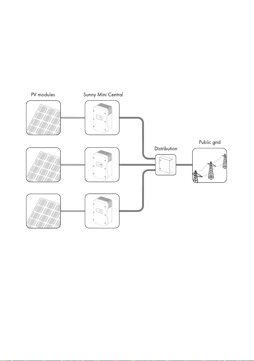
2 Security
2.1 Appropriate Usage
The Sunny Mini Central is a PV inverter that converts the DC current of solar cells to AC current and
feeds it into the public grid.
Principle of a PV System with the Sunny Mini Central
L1
L2
L3
The Sunny Mini Central may only be operated with PV generators (modules and cabling) of
protection class II. Do not connect any sources of energy other than PV modules to the Sunny Mini
Central.
PV modules with large capacities relative to ground, such as thin-film modules with cells on a metallic
substrate, are therefore only to be implemented if their coupling capacitance is below 50 nF/kWp.
During grid feeding, a leakage current flows from the cells to the earth. The magnitude of this current
depends on the manner in which the modules are installed and, to no small extent, on the weather
(rain, snow). This operational leakage current is not to exceed 50 mA.
When designing the PV system, ensure that the values comply with the permitted operating range of
all components at all times. The free design program "Sunny Design" (www.SMA.de/SunnyDesign)
will assist you. The manufacturer of the PV modules must have approved the modules for use with this
Sunny Mini Central unit. You must also ensure that all measures recommended by the module
manufacturer for long-term maintenance of the module properties are taken (see also Technical
Information "Module Technology", in the download area of www.SMA.de).
Installation Guide SMC9-11TL-IEN083620 9
Security SMA Solar Technology AG
Do not use the Sunny Boy for purposes other than those described here. Alternative uses,
modifications to the Sunny Boy or the installation of components not expressly recommended or sold
by the manufacturer void the warranty claims and operating license.
2.2 Safety Precautions
DANGER!
Danger to life due to high voltages in the Sunny Mini Central!
All work on the Sunny Mini Central must be carried out by a qualified electrician.
DANGER!
Danger of burn injuries due to hot housing parts!
• Do not touch the housing body during operation.
• Only touch the cover during operation.
NOTICE!
Dust or water entering the Sunny Mini Central can damage the device!
If the Electronic Solar Switch has been pulled out, the Sunny Mini Central only has a
protection rating of IP21.
If the device has been temporarily decommiss ioned, proceed a s follows to restore the IP65
protection rating:
• Unplug all DC plug connectors and seal them with the protecting caps provided.
• Attach the Electronic Solar Switch.
Grounding the PV generator
Comply with the local requirements for grounding the modules and the PV generator.
SMA Solar Technology recommends connecting the generator frame and other electricity
conducting surfaces such that there is continuous conduction and to connect them to the
ground in order to reach maximum protection for property and persons.
10 SMC9-11TL-IEN083620 Installation Guide
SMA Solar Technology AG Unpacking
3 Unpacking
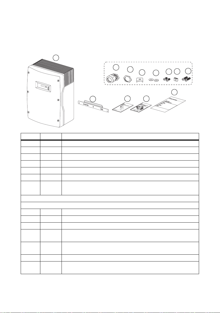
3.1 Delivery Scope
A
F
G
H
B
Object Quantity Description
A 1 Sunny Mini Central
B1 wall mounting bracket
C1 installation guide
D1 user manual
E 1 set of documents with explanations and certificates
1 Inverter accessories bag
1 Communication accessories bag (optional),
for packing list see separate communication manual
C
D
J
A
L
K
E
Contents of inverter accessories bag:
F 1 cable screw connection for AC connection:
G 1 nut for AC connection cable screw connection
H 1 clamping clip for additional connection to ground
I 2 washers: 1 x for cover screws (replacement), 1 x for ground connection
cable terminal
J 2 cylinder head screws (M6 x 16): 1 x for cover (replacement),
1 x for ground connection cable terminal
K 1 jumper for fan test
L 2 cylinder head screws (M6 x 8) for securing the Sunny Mini Central on the
wall mounting bracket
Installation Guide SMC9-11TL-IEN083620 11
Unpacking SMA Solar Technology AG
3.2 Check for Transport Damage
Check the Sunny Mini Central for visible external damage, such as cracks in the housing or display.
Please contact your dealer if you find any damage.
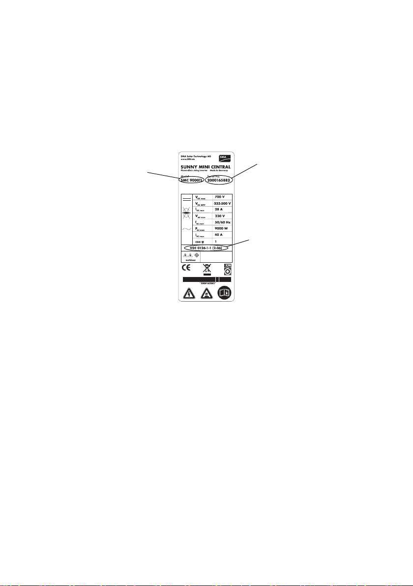
3.3 Identifying the Sunny Mini Central
You can identify the Sunny Mini Central using the type label. The type label is on the right side of the
housing.
Devicetype
Serial number
Country-specific
standard for the grid
isolation point
according to which
the device may be
preset
12 SMC9-11TL-IEN083620 Installation Guide
SMA Solar Technology AG Mounting
4 Mounting
4.1 Selection of the Mounting Location
DANGER!
Danger to life due to fire or explosion!
Despite careful construction, a fire can occur with electrical devices.
• Do not mount the Sunny Mini Central on flammable construction materials.
• Do not mount the Sunny Mini Central in areas where highly flammable materials are
stored.
• Do not mount the Sunny Mini Central in areas where there is a risk of explosion.
CAUTION!
Danger of burn injuries due to hot housing parts!
• Mount the Sunny Mini Central such that it cannot be touched inadvertently.
4.1.1 Dimensions and Weight
m
m
3
1
6
4
6
8
m
m
35 kg
Installation Guide SMC9-11TL-IEN083620 13
m
m
2
4
2
Mounting SMA Solar Technology AG
4.1.2 Ambient Conditions
• The mounting location and mounting method must be suitable for the weight and dimensions of
the Sunny Mini Central.
• Mounting on a solid surface.
• The mounting location must be accessible at all times.
• The ambient temperature should be below 40 °C at all times to guarantee optimal operation.
• Do not expose the Sunny Mini Central to direct sunlight to avoid a power reduction due to
excessive heating.
• In a living area, do not mount the unit on
plasterboard etc. walls as otherwise audible
vibrations are likely to result.
The Sunny Mini Central can make noises when in
us e which can be se en a s a nuis anc e when i nst alled
in a living area.
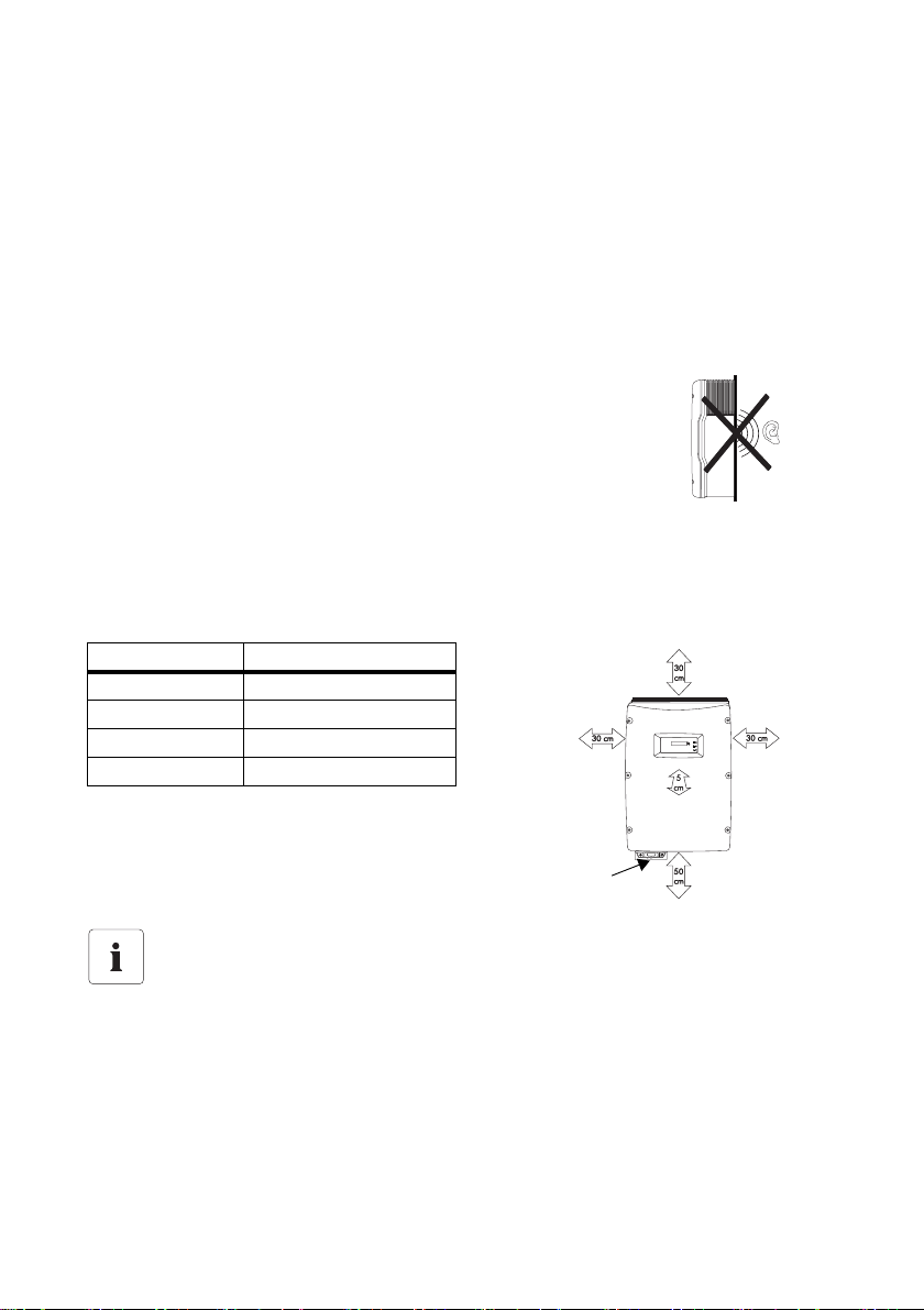
4.1.3 Safety Clearances
Observe the following minimum clearances to walls, other devices or objects to guarantee sufficient
heat dissipation and enough space for pulling the Electronic Solar Switch handle.
Direction Minimum Clearance
Sidewise 30 cm
Above 30 cm
Bottom 50 cm
Front 5 cm
Electronic
Solar
Switch
Multiple Sunny Mini Centrals installed in areas with high ambient temperatures
The individual Sunny Mini Central units must be far enough apart to ensure that the
individual Sunny Mini Central units do not take in the cooling air of the neighboring unit.
If necessary, increase the clearance and ensure that the supply of cool air is sufficient to
cool the Sunny Mini Centrals.
14 SMC9-11TL-IEN083620 Installation Guide
SMA Solar Technology AG Mounting
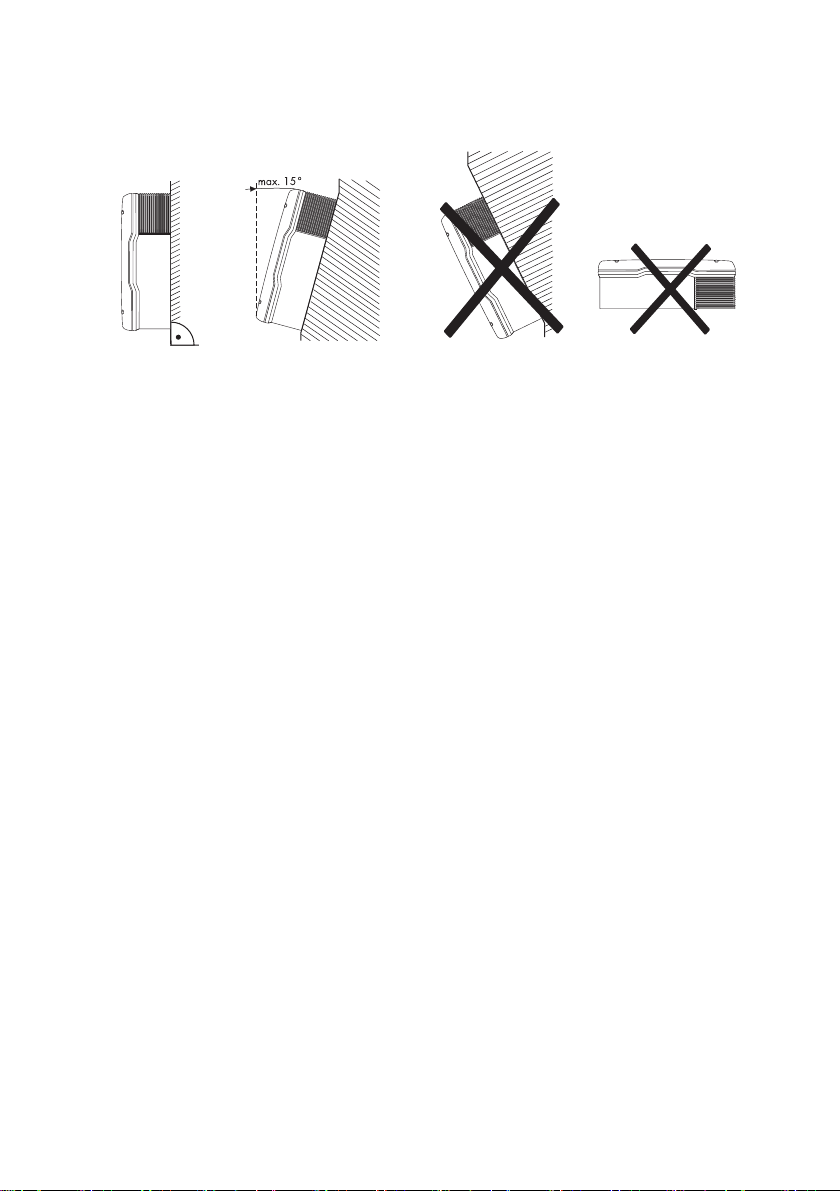
4.1.4 Position
• Vertical installation or tilted backwards by max. 15°.
• Never install the unit with a forward tilt.
• Do not install horizontally.
• Install at eye level to allow operating modes to be read at all times.
Installation Guide SMC9-11TL-IEN083620 15
Mounting SMA Solar Technology AG
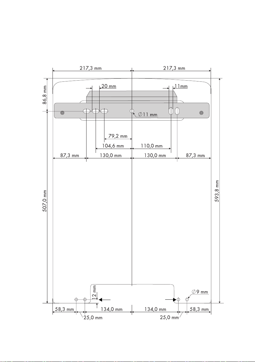
4.2 Mounting Instructions
1. Mark the position of the drill holes using the wall mounting bracket and drill the holes. In doing
so, use two to four of the six holes in the middle.
Holes for optional
single-use screws as anti-theft
protection
16 SMC9-11TL-IEN083620 Installation Guide
SMA Solar Technology AG Mounting
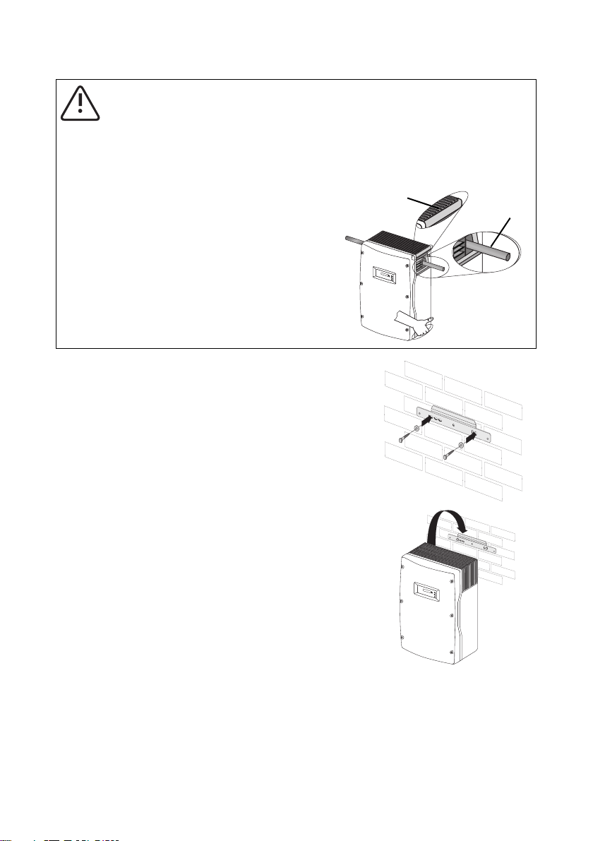
CAUTION!
Risk of injury due to the heavy weight of the Sunny Mini Central!
The Sunny Mini Central weighs approximately 35 kg
• Attach the wall mounting bracket with the corresponding mounting material
(depending on the surface).
• Use the side handles above and below
(A) or place a steel rod in the housing
opening (B, max. diameter 30 mm) for
A
B
transport and assembly.
2. Secure the wall mounting bracket using suitable
screws and washers.
3. Attach the Sunny Mini Central to the wall mounting
bracket using the mounting opening in the rear wall
of the housing.
Installation Guide SMC9-11TL-IEN083620 17

Mounting SMA Solar Technology AG
4. Screw the Sunny Mini Central onto the wall
mounting bracket on both sides using the
M6 x 8 mm screws provided.
Only fasten the screws using your hand!
5. Check that the unit is securely in place.
6. Close the recessed grips with the handle covers
provided in the accessories kit.
2.
The handle covers prevent dirt and insects from
entering the device and if necessary, can be
reordered from SMA Solar Technology
1.
(SMA order number: 45-7202, contact: see
Page 65).
Optional Anti-theft Protection
To protect the Sunny Mini Central against
theft, the rear face can be secured to the wall
at the bottom using two single-use bolts.
The other two holes are spares.
18 SMC9-11TL-IEN083620 Installation Guide
SMA Solar Technology AG Electrical Connection
5 Electrical Connection
NOTICE!
Electrostatic discharges can damage the Sunny Mini Central!
Internal components of the Sunny Mini Central can be irreparably damaged by static
discharge.
• Ground yourself before you touch a component.
5.1 Overview of the Connection Area
5.1.1 View from Below
The following figure shows the assignment of the individual housing openings on the base of the
Sunny Mini Central.
A
A Plug connectors for connecting the PV strings
B Socket for the connection of the Electronic Solar Switch (ESS) DC load disconnection unit
C Cable openings for optional communication via RS232, RS485 or radio (PG16)
D Power Balancer Connection
E Cable opening for grid connection (AC) (18 mm - 32 mm)
B
A
C
D E
Installation Guide SMC9-11TL-IEN083620 19
Electrical Connection SMA Solar Technology AG
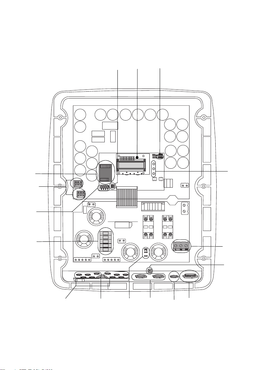
5.1.2 View from Inside
The following diagram gives a schematic overview of the various components and connection points
inside the Sunny Mini Central with the cover removed.
A
P
B
C
D
O
N
M
E
F
L
20 SMC9-11TL-IEN083620 Installation Guide
K
J
I
G
H

SMA Solar Technology AG Electrical Connection
A Jumper for communication (Page 43)
B Display (Page 45)
C Jumper for fan testing (Page 55)
D Operating status LEDs (Page 48)
E Connection terminals for mains cable (AC) (Page 24)
F Screwing device for shield clamp for communication cable (Page 43)
G Cable opening for mains cable (AC) (Page 24)
H Connection socket for Power Balancer (Page 34)
I Cable openings for communication (Page 43)
J Tab for grounding the cable shield with communication (Page 43)
K Connection socket for “Electronic Solar Switch (ESS)” DC load disconnection unit (Page 30)
L PV input plug (DC) (Page 30)
M Slot for string fuses (Page 28)
N Connection terminal for communication (Page 43)
O Varistors (Page 60)
P Slot for communication interface (Page 43)
Installation Guide SMC9-11TL-IEN083620 21
 Loading...