

Page 1
Stand-alone grid inverter
Sunny Island 2012/2224
Technical Description
SI2012_2224-TEN082311 | 98-2005110 | Version 1.1
EN
Page 2
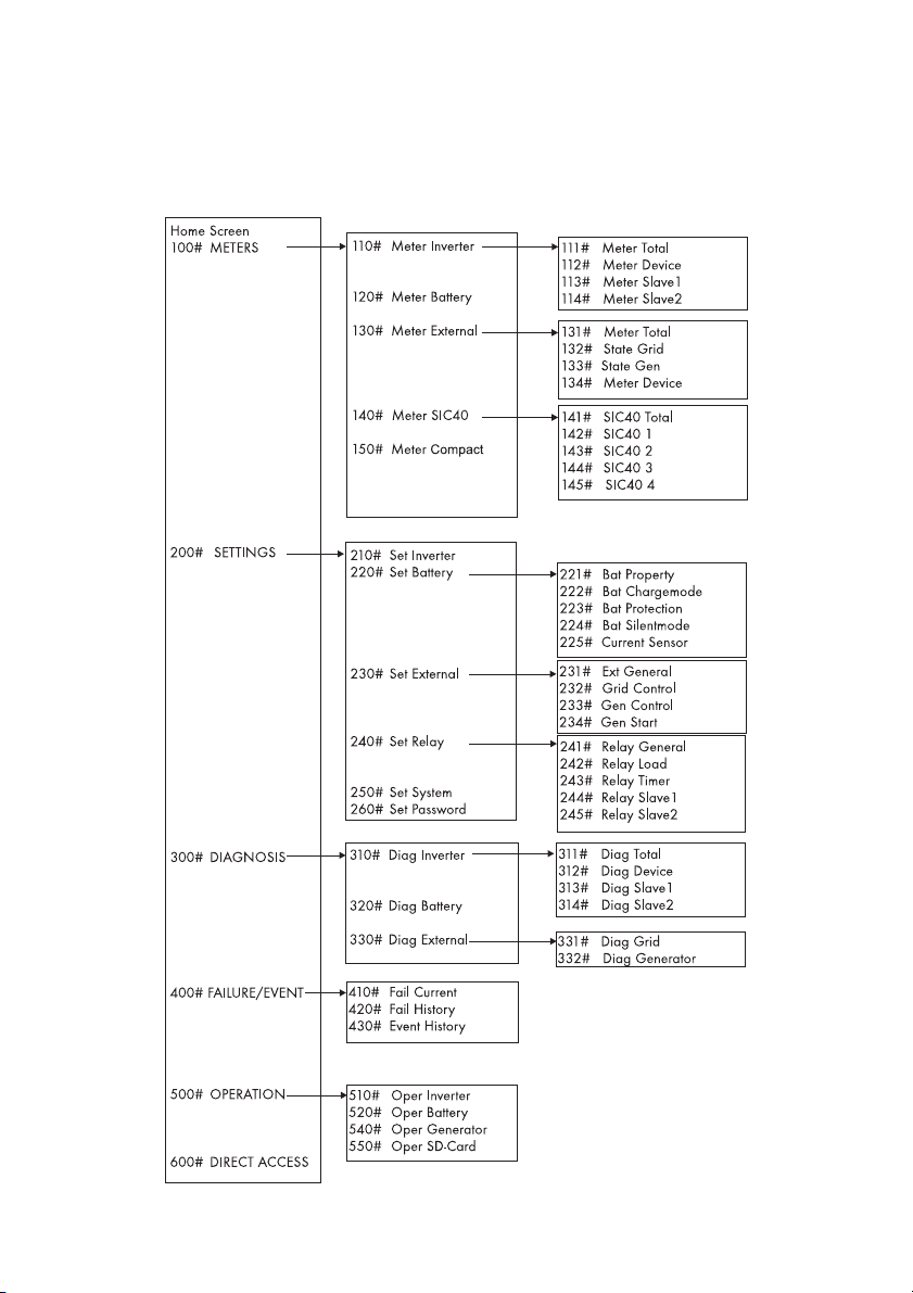
Overview of the menu area:
Main menu
Submenu 1
Submenu 2
Page 3

SMA Solar Technology AG Table of Contents
Table of Contents
1 Notes on this Manual. . . . . . . . . . . . . . . . . . . . . . . . . . . . . . 9
1.1 Validity . . . . . . . . . . . . . . . . . . . . . . . . . . . . . . . . . . . . . . . . . . . . 9
1.2 Target Group . . . . . . . . . . . . . . . . . . . . . . . . . . . . . . . . . . . . . . 10
1.3 Storage of the Documentation . . . . . . . . . . . . . . . . . . . . . . . . . 10
1.4 Explanation of the Symbols Used . . . . . . . . . . . . . . . . . . . . . . 10
1.5 Syntax. . . . . . . . . . . . . . . . . . . . . . . . . . . . . . . . . . . . . . . . . . . . 11
2 System Overview. . . . . . . . . . . . . . . . . . . . . . . . . . . . . . . . 12
3 Safety Instructions . . . . . . . . . . . . . . . . . . . . . . . . . . . . . . . 16
4 Unpacking. . . . . . . . . . . . . . . . . . . . . . . . . . . . . . . . . . . . . . 17
4.1 Scope of delivery . . . . . . . . . . . . . . . . . . . . . . . . . . . . . . . . . . . 18
4.1.1 Sunny Island 2012/2224 . . . . . . . . . . . . . . . . . . . . . . . . . . . . . . . . . . . . . . 18
4.1.2 Sunny Remote Control 1 . . . . . . . . . . . . . . . . . . . . . . . . . . . . . . . . . . . . . . . 19
4.2 Name Plate/Firmware Version . . . . . . . . . . . . . . . . . . . . . . . . 20
4.2.1 Sunny Island 2012/2224 . . . . . . . . . . . . . . . . . . . . . . . . . . . . . . . . . . . . . . 20
4.2.2 Sunny Remote Control 1 . . . . . . . . . . . . . . . . . . . . . . . . . . . . . . . . . . . . . . . 21
5 Installation . . . . . . . . . . . . . . . . . . . . . . . . . . . . . . . . . . . . . 22
5.1 Required Tools and Resources. . . . . . . . . . . . . . . . . . . . . . . . . 22
5.2 Sunny Island 2012/2224. . . . . . . . . . . . . . . . . . . . . . . . . . . . 23
5.2.1 Dimensions . . . . . . . . . . . . . . . . . . . . . . . . . . . . . . . . . . . . . . . . . . . . . . . . . . 23
5.2.2 Choosing a Mounting Location . . . . . . . . . . . . . . . . . . . . . . . . . . . . . . . . . . 24
5.2.3 Observe minimum clearances . . . . . . . . . . . . . . . . . . . . . . . . . . . . . . . . . . . 25
5.2.4 Mounting Position. . . . . . . . . . . . . . . . . . . . . . . . . . . . . . . . . . . . . . . . . . . . . 26
5.2.5 Mounting the Sunny Island with a Wall Mounting Bracket. . . . . . . . . . . . . 27
5.3 Sunny Remote Control 1 . . . . . . . . . . . . . . . . . . . . . . . . . . . . . 31
5.3.1 Dimensions . . . . . . . . . . . . . . . . . . . . . . . . . . . . . . . . . . . . . . . . . . . . . . . . . . 31
5.3.2 Choosing a Mounting Location . . . . . . . . . . . . . . . . . . . . . . . . . . . . . . . . . . 31
5.3.3 Wall Mounting . . . . . . . . . . . . . . . . . . . . . . . . . . . . . . . . . . . . . . . . . . . . . . . 32
5.4 Installing Batteries. . . . . . . . . . . . . . . . . . . . . . . . . . . . . . . . . . . 33
Technical Description SI2012_2224-TEN082311 3
Page 4

Table of Contents SMA Solar Technology AG
6 Opening and Closing. . . . . . . . . . . . . . . . . . . . . . . . . . . . . 36
6.1 Opening the Sunny Island . . . . . . . . . . . . . . . . . . . . . . . . . . . . 37
6.2 Closing the Sunny Island . . . . . . . . . . . . . . . . . . . . . . . . . . . . . 38
7 Sunny Island Electrical Connection. . . . . . . . . . . . . . . . . . 39
7.1 At a Glance . . . . . . . . . . . . . . . . . . . . . . . . . . . . . . . . . . . . . . . 40
7.2 DC connection . . . . . . . . . . . . . . . . . . . . . . . . . . . . . . . . . . . . . 43
7.2.1 Grounding . . . . . . . . . . . . . . . . . . . . . . . . . . . . . . . . . . . . . . . . . . . . . . . . . . 43
7.2.2 Connecting the Battery. . . . . . . . . . . . . . . . . . . . . . . . . . . . . . . . . . . . . . . . . 44
7.2.3 Connecting the Sunny Island . . . . . . . . . . . . . . . . . . . . . . . . . . . . . . . . . . . . 45
7.3 AC Connection. . . . . . . . . . . . . . . . . . . . . . . . . . . . . . . . . . . . . 46
7.3.1 Grounding . . . . . . . . . . . . . . . . . . . . . . . . . . . . . . . . . . . . . . . . . . . . . . . . . . 47
7.3.2 AC1 (Loads/Sunny Boys) . . . . . . . . . . . . . . . . . . . . . . . . . . . . . . . . . . . . . . 48
7.3.3 AC2 (Gen/Grid) . . . . . . . . . . . . . . . . . . . . . . . . . . . . . . . . . . . . . . . . . . . . . 50
7.4 Sunny Remote Control 1 . . . . . . . . . . . . . . . . . . . . . . . . . . . . . 51
7.5 Communication . . . . . . . . . . . . . . . . . . . . . . . . . . . . . . . . . . . . 53
7.5.1 Communication with Sunny Island . . . . . . . . . . . . . . . . . . . . . . . . . . . . . . . . 53
7.5.2 Communication With External Devices . . . . . . . . . . . . . . . . . . . . . . . . . . . . 56
7.6 Additional Connections . . . . . . . . . . . . . . . . . . . . . . . . . . . . . . 59
7.6.1 Battery Temperature Sensor . . . . . . . . . . . . . . . . . . . . . . . . . . . . . . . . . . . . . 59
7.6.2 Battery Current Sensor . . . . . . . . . . . . . . . . . . . . . . . . . . . . . . . . . . . . . . . . . 61
7.6.3 Multi-function Relays 1 and 2 . . . . . . . . . . . . . . . . . . . . . . . . . . . . . . . . . . . 63
7.6.4 BatVtgOut Power Supply . . . . . . . . . . . . . . . . . . . . . . . . . . . . . . . . . . . . . . . 66
7.6.5 DigIn Digital Input. . . . . . . . . . . . . . . . . . . . . . . . . . . . . . . . . . . . . . . . . . . . . 66
7.7 Configuring a System with Several Sunny Islands. . . . . . . . . . 68
7.8 Concluding Tasks . . . . . . . . . . . . . . . . . . . . . . . . . . . . . . . . . . . 69
8 Control Elements . . . . . . . . . . . . . . . . . . . . . . . . . . . . . . . . 70
8.1 Sunny Island. . . . . . . . . . . . . . . . . . . . . . . . . . . . . . . . . . . . . . . 70
8.1.1 Control Panel on the Enclosure . . . . . . . . . . . . . . . . . . . . . . . . . . . . . . . . . . 70
8.1.2 Control Panel Buttons . . . . . . . . . . . . . . . . . . . . . . . . . . . . . . . . . . . . . . . . . . 70
8.1.3 Meaning of the Light-Emitting Diodes (LEDs) . . . . . . . . . . . . . . . . . . . . . . . . 70
8.2 Sunny Remote Control 1 . . . . . . . . . . . . . . . . . . . . . . . . . . . . . 72
4 SI2012_2224-TEN082311 Technical Description
Page 5

SMA Solar Technology AG Table of Contents
8.2.1 Display Messages . . . . . . . . . . . . . . . . . . . . . . . . . . . . . . . . . . . . . . . . . . . . 73
8.2.2 Key . . . . . . . . . . . . . . . . . . . . . . . . . . . . . . . . . . . . . . . . . . . . . . . . . . . . . . . . 73
8.2.3 Rotating Pushbutton . . . . . . . . . . . . . . . . . . . . . . . . . . . . . . . . . . . . . . . . . . . 74
8.2.4 MMC/SD card. . . . . . . . . . . . . . . . . . . . . . . . . . . . . . . . . . . . . . . . . . . . . . . 74
9 (First) Commissioning. . . . . . . . . . . . . . . . . . . . . . . . . . . . . 75
9.1 Requirements . . . . . . . . . . . . . . . . . . . . . . . . . . . . . . . . . . . . . . 75
9.2 Starting the Quick Configuration Guide (QCG) . . . . . . . . . . . 76
9.3 Commissioning the Battery Current Sensor . . . . . . . . . . . . . . . 81
10 Operating the Sunny Island . . . . . . . . . . . . . . . . . . . . . . . 83
10.1 Switching On and Off . . . . . . . . . . . . . . . . . . . . . . . . . . . . . . . 83
10.1.1 Switching On/Starting . . . . . . . . . . . . . . . . . . . . . . . . . . . . . . . . . . . . . . . . . 83
10.1.2 Stopping . . . . . . . . . . . . . . . . . . . . . . . . . . . . . . . . . . . . . . . . . . . . . . . . . . . . 85
10.1.3 Switching Off . . . . . . . . . . . . . . . . . . . . . . . . . . . . . . . . . . . . . . . . . . . . . . . . 87
10.1.4 Disconnecting the Device from Voltage Sources . . . . . . . . . . . . . . . . . . . . . 87
10.1.5 Restarting the System after Automatic Shutdown. . . . . . . . . . . . . . . . . . . . . 88
10.2 Navigation Area . . . . . . . . . . . . . . . . . . . . . . . . . . . . . . . . . . . 89
10.2.1 Standard View 1 . . . . . . . . . . . . . . . . . . . . . . . . . . . . . . . . . . . . . . . . . . . . . 92
10.2.2 Standard View 2 . . . . . . . . . . . . . . . . . . . . . . . . . . . . . . . . . . . . . . . . . . . . . 93
10.2.3 Select menu . . . . . . . . . . . . . . . . . . . . . . . . . . . . . . . . . . . . . . . . . . . . . . . . . 97
10.2.4 Selecting Parameters . . . . . . . . . . . . . . . . . . . . . . . . . . . . . . . . . . . . . . . . . . 99
10.2.5 Selecting Events . . . . . . . . . . . . . . . . . . . . . . . . . . . . . . . . . . . . . . . . . . . . . . 99
10.2.6 Selecting Warnings and Faults. . . . . . . . . . . . . . . . . . . . . . . . . . . . . . . . . . 100
10.3 Making adjustments . . . . . . . . . . . . . . . . . . . . . . . . . . . . . . . .101
10.3.1 Adjusting parameters . . . . . . . . . . . . . . . . . . . . . . . . . . . . . . . . . . . . . . . . . 101
10.3.2 Setting the Installer Password. . . . . . . . . . . . . . . . . . . . . . . . . . . . . . . . . . . 102
10.3.3 Accessing Parameters Directly . . . . . . . . . . . . . . . . . . . . . . . . . . . . . . . . . . 105
10.3.4 Meter Compact . . . . . . . . . . . . . . . . . . . . . . . . . . . . . . . . . . . . . . . . . . . . . 105
10.4 Saving Data onto a MMC/SD Card. . . . . . . . . . . . . . . . . . . 107
10.4.1 Inserting the Card. . . . . . . . . . . . . . . . . . . . . . . . . . . . . . . . . . . . . . . . . . . . 111
10.4.2 Removing the Card. . . . . . . . . . . . . . . . . . . . . . . . . . . . . . . . . . . . . . . . . . . 112
10.4.3 Loading and Saving Parameters . . . . . . . . . . . . . . . . . . . . . . . . . . . . . . . . 112
10.4.4 Writing Log Data . . . . . . . . . . . . . . . . . . . . . . . . . . . . . . . . . . . . . . . . . . . . 113
Technical Description SI2012_2224-TEN082311 5
Page 6

Table of Contents SMA Solar Technology AG
10.4.5 Show Status . . . . . . . . . . . . . . . . . . . . . . . . . . . . . . . . . . . . . . . . . . . . . . . . 113
10.4.6 Updating Firmware. . . . . . . . . . . . . . . . . . . . . . . . . . . . . . . . . . . . . . . . . . . 114
11 Additional Functions . . . . . . . . . . . . . . . . . . . . . . . . . . . . 117
11.1 Load shedding . . . . . . . . . . . . . . . . . . . . . . . . . . . . . . . . . . . . 117
11.2 Sleep Mode . . . . . . . . . . . . . . . . . . . . . . . . . . . . . . . . . . . . . . 118
11.3 Search Mode . . . . . . . . . . . . . . . . . . . . . . . . . . . . . . . . . . . . . 118
11.4 Time-controlled Operation . . . . . . . . . . . . . . . . . . . . . . . . . . . 119
11.5 Overload and Short Circuit Behavior . . . . . . . . . . . . . . . . . . 119
11.6 Device Failure and Autostart . . . . . . . . . . . . . . . . . . . . . . . . . 119
12 Battery management . . . . . . . . . . . . . . . . . . . . . . . . . . . . 120
12.1 Battery temperature. . . . . . . . . . . . . . . . . . . . . . . . . . . . . . . . 120
12.2 Start Options . . . . . . . . . . . . . . . . . . . . . . . . . . . . . . . . . . . . . 121
12.3 Charge State/SOC and SOH . . . . . . . . . . . . . . . . . . . . . . . . 121
12.4 Charge Control . . . . . . . . . . . . . . . . . . . . . . . . . . . . . . . . . . .122
12.4.1 Boost Charge . . . . . . . . . . . . . . . . . . . . . . . . . . . . . . . . . . . . . . . . . . . . . . . 124
12.4.2 Full Charge . . . . . . . . . . . . . . . . . . . . . . . . . . . . . . . . . . . . . . . . . . . . . . . . . 124
12.4.3 Equalization Charge . . . . . . . . . . . . . . . . . . . . . . . . . . . . . . . . . . . . . . . . . 126
12.4.4 Manual Equalization Charge. . . . . . . . . . . . . . . . . . . . . . . . . . . . . . . . . . . 127
12.4.5 Silent Mode . . . . . . . . . . . . . . . . . . . . . . . . . . . . . . . . . . . . . . . . . . . . . . . . 127
12.5 Battery Preservation Mode . . . . . . . . . . . . . . . . . . . . . . . . . . 127
12.6 Battery Diagnostics. . . . . . . . . . . . . . . . . . . . . . . . . . . . . . . . . 129
13 Connecting External Sources . . . . . . . . . . . . . . . . . . . . . 130
13.1 Generator. . . . . . . . . . . . . . . . . . . . . . . . . . . . . . . . . . . . . . . . 130
13.1.1 Connecting Generator Connections in Parallel . . . . . . . . . . . . . . . . . . . . . 131
13.1.2 Generator Start Options. . . . . . . . . . . . . . . . . . . . . . . . . . . . . . . . . . . . . . . 131
13.1.3 Generator Operation . . . . . . . . . . . . . . . . . . . . . . . . . . . . . . . . . . . . . . . . . 135
13.1.4 Manual Generator Operation . . . . . . . . . . . . . . . . . . . . . . . . . . . . . . . . . . 135
13.1.5 Automatic Generator Operation . . . . . . . . . . . . . . . . . . . . . . . . . . . . . . . . 137
13.1.6 Limits and Power Adjustment . . . . . . . . . . . . . . . . . . . . . . . . . . . . . . . . . . . 141
13.1.7 Run Times . . . . . . . . . . . . . . . . . . . . . . . . . . . . . . . . . . . . . . . . . . . . . . . . . . 143
6 SI2012_2224-TEN082311 Technical Description
Page 7

SMA Solar Technology AG Table of Contents
13.1.8 Operation Together With Sunny Boys . . . . . . . . . . . . . . . . . . . . . . . . . . . . 144
13.1.9 Stopping the Generator . . . . . . . . . . . . . . . . . . . . . . . . . . . . . . . . . . . . . . . 145
13.1.10 Failures . . . . . . . . . . . . . . . . . . . . . . . . . . . . . . . . . . . . . . . . . . . . . . . . . . . . 146
13.2 Grid . . . . . . . . . . . . . . . . . . . . . . . . . . . . . . . . . . . . . . . . . . . . 146
13.2.1 Conditions. . . . . . . . . . . . . . . . . . . . . . . . . . . . . . . . . . . . . . . . . . . . . . . . . . 147
13.2.2 Stand-Alone Grid Operation . . . . . . . . . . . . . . . . . . . . . . . . . . . . . . . . . . . 147
13.2.3 Grid Reconnection . . . . . . . . . . . . . . . . . . . . . . . . . . . . . . . . . . . . . . . . . . . 147
13.2.4 Grid Operation. . . . . . . . . . . . . . . . . . . . . . . . . . . . . . . . . . . . . . . . . . . . . . 148
13.2.5 Grid Failure. . . . . . . . . . . . . . . . . . . . . . . . . . . . . . . . . . . . . . . . . . . . . . . . . 149
13.2.6 Failures . . . . . . . . . . . . . . . . . . . . . . . . . . . . . . . . . . . . . . . . . . . . . . . . . . . . 149
13.2.7 Limits and Power Adjustment . . . . . . . . . . . . . . . . . . . . . . . . . . . . . . . . . . . 149
13.2.8 Operation Together With Sunny Boys . . . . . . . . . . . . . . . . . . . . . . . . . . . . 150
13.3 Generator and Grid. . . . . . . . . . . . . . . . . . . . . . . . . . . . . . . . 151
14 Relay . . . . . . . . . . . . . . . . . . . . . . . . . . . . . . . . . . . . . . . . . 152
15 Sunny Boy in the Island Grid System . . . . . . . . . . . . . . . 154
15.1 Setting the Stand-alone Grid Parameters. . . . . . . . . . . . . . . . 154
15.2 Frequency Shift Power Control (FSPC) . . . . . . . . . . . . . . . . .156
16 Maintenance and Care . . . . . . . . . . . . . . . . . . . . . . . . . . 158
16.1 Enclosure . . . . . . . . . . . . . . . . . . . . . . . . . . . . . . . . . . . . . . . . 158
16.2 The Sunny Island's Control Panel. . . . . . . . . . . . . . . . . . . . . . 158
16.3 Sunny Remote Control 1 . . . . . . . . . . . . . . . . . . . . . . . . . . . . 158
16.4 Functional Test . . . . . . . . . . . . . . . . . . . . . . . . . . . . . . . . . . . . 158
16.5 Battery . . . . . . . . . . . . . . . . . . . . . . . . . . . . . . . . . . . . . . . . . .159
16.6 Disposal . . . . . . . . . . . . . . . . . . . . . . . . . . . . . . . . . . . . . . . . . 159
17 Parameter List Overview. . . . . . . . . . . . . . . . . . . . . . . . . 160
17.1 Display Values . . . . . . . . . . . . . . . . . . . . . . . . . . . . . . . . . . . . 162
17.2 Adjustable System Parameters . . . . . . . . . . . . . . . . . . . . . . . . 166
17.3 Diagnosis . . . . . . . . . . . . . . . . . . . . . . . . . . . . . . . . . . . . . . . . 178
17.4 Events, Warnings and Failures (History) . . . . . . . . . . . . . . . . 182
Technical Description SI2012_2224-TEN082311 7
Page 8

Table of Contents SMA Solar Technology AG
17.5 Functions During Operation. . . . . . . . . . . . . . . . . . . . . . . . . . 182
18 Troubleshooting/Problem Solving . . . . . . . . . . . . . . . . . 184
18.1 Error Confirmation . . . . . . . . . . . . . . . . . . . . . . . . . . . . . . . . . 184
18.2 Handling Autostart . . . . . . . . . . . . . . . . . . . . . . . . . . . . . . . . .184
18.3 Handling Failures Present During Startup . . . . . . . . . . . . . . . 184
18.4 Display of Failures and Events . . . . . . . . . . . . . . . . . . . . . . . . 184
18.5 Events . . . . . . . . . . . . . . . . . . . . . . . . . . . . . . . . . . . . . . . . . . . 185
18.6 Error Categories. . . . . . . . . . . . . . . . . . . . . . . . . . . . . . . . . . . 188
18.7 Warnings and Failure messages . . . . . . . . . . . . . . . . . . . . . . 188
18.8 Troubleshooting . . . . . . . . . . . . . . . . . . . . . . . . . . . . . . . . . . .192
19 Optional Devices . . . . . . . . . . . . . . . . . . . . . . . . . . . . . . . 195
19.1 External DC fuse. . . . . . . . . . . . . . . . . . . . . . . . . . . . . . . . . . . 195
19.2 External DC charge controllers (optional) . . . . . . . . . . . . . . . 195
19.3 Accessories (Optional). . . . . . . . . . . . . . . . . . . . . . . . . . . . . . 195
19.4 SMA Products (Optional). . . . . . . . . . . . . . . . . . . . . . . . . . . . 196
20 Technical Data . . . . . . . . . . . . . . . . . . . . . . . . . . . . . . . . . 197
20.1 Sunny Island 2012/2224. . . . . . . . . . . . . . . . . . . . . . . . . . . 197
20.2 Sunny Remote Control 1 . . . . . . . . . . . . . . . . . . . . . . . . . . . . 200
21 Contact . . . . . . . . . . . . . . . . . . . . . . . . . . . . . . . . . . . . . . . 201
22 Glossary . . . . . . . . . . . . . . . . . . . . . . . . . . . . . . . . . . . . . . 202
8 SI2012_2224-TEN082311 Technical Description
Page 9
SMA Solar Technology AG Notes on this Manual
1 Notes on this Manual
This technical description explains the functioning, correct installation and operation of a standalone grid system. It describes the Sunny Island 2012 / 2224 inverter as well as the Sunny Remote
Control 1 display.
Information on the following topics can be found in the respectively labeled sections:
- Installation: Chapter 2 "System Overview" (Page 12)
- Commissioning: Chapter 8 "Control Elements" (Page 70)
- Functions: Chapter 11 "Additional Functions" (Page 117)
- Appendix: Chapter 16 "Maintenance and Care" (Page 158)
1.1 Validity
The technical description applies to the Sunny Island 2012 / 2224 firmware versions 2.0 and later
(see chapter 4.2 "Name Plate/Firmware Version" (Page 20)).
You can read the firmware version of your Sunny Island 2012 / 2224 on the display using the
"312.02 FwVer" parameter (see section 17.3 "Diagnosis" (Page 178)).
Information
The following applications are only possible with firmware versions 3.0 and above:
• Connection of two or three Sunny Island 2012 / 2224 devices to a 1-phase
parallel system
• Connection of two or three Sunny Island 2012 / 2224 devices to a 3-phase
parallel system
The stand-alone grid system devices may only be operated within the intended area of application
described in this documentation.
• The use of a stand-alone grid system to power life-sustaining medical devices is not permitted.
• The Sunny Reomet Control 1 is suited only for installation in enclosed spaces (protection rating
IP20).
• The Sunny Island 2012 / 2224 has been designed for use at elevations of up to 2600 m
above sea level. Please contact SMA Solar Technology AG before using the device at
elevations above 2600 m.
A performance loss of 0.5 % per every 100 m is to be expected starting at an elevation of
2000 m above sea level.
Technical Description SI2012_2224-TEN082311 9
Page 10
Notes on this Manual SMA Solar Technology AG
Do not use the stand-alone grid system devices for purposes other than those indicated in this
technical description. Use of the devices for other purposes can void the warranty as well as
damage both the devices and the system.
For further questions, you can call the Sunny Island hotline at
• +49561 95 22 399
• E-Mail: [email protected].
1.2 Target Group
This technical description is meant both for the installer and the operator of the stand-alone grid
system. Some of the tasks described in this document must be performed only by qualified
electricians and are labeled accordingly with warnings.
1.3 Storage of the Documentation
The manuals for the stand-alone grid system and its installed components must be kept in the
immediate vicinity of the Sunny Island so as to be accessible at all times.
1.4 Explanation of the Symbols Used
The following types of safety warnings are used in this document:
DANGER!
"DANGER" indicates a hazardous situation which, if not avoided, will result in death or
serious injury.
WARNING!
"WARNING" indicates a hazardous situation which, if not avoided, could result in death
or serious injury.
CAUTION!
"CAUTION" indicates a hazardous situation which, if not avoided, could result in minor
or moderate injury.
10 SI2012_2224-TEN082311 Technical Description
Page 11
SMA Solar Technology AG Notes on this Manual
Notice!
"NOTICE!" designates a safety warning about a condition which can lead to property
damage if the warning is ignored.
Information
"Notice" designates information which is important for the optimal operation of the
product.
1.5 Syntax
The syntax specified here for menus and parameters applies throughout the entire document:
Menu: Menu number, hash and menu name (150# Meter Compact)
Parameter:
Menu number, dot, parameter number and parameter name
(150.01 GdRmgTm)
Information
The parameter names used are based on the international IEC 61850-7-4 and
61400-25 standards.
Technical Description SI2012_2224-TEN082311 11
Page 12
System Overview SMA Solar Technology AG
2 System Overview
The Sunny Island is a bi-directional battery inverter (battery inverter and charger) for off-grid
systems. The Sunny Island supplies consumers on the stand-alone grid side and charges battery
banks with the energy from grid-feeding units connected on the AC side.
High efficiency
The comfortable support of AC- and DC coupling as well as the expandability of the systems formed
with the Sunny Island guarantee highest flexibility. In addition, innovative technology allows the
Sunny Island to achieve a maximum efficiency of more than 93 %. Optimized for partial load
operation, its low open-circuit and standby consumption are convincing features. Because of its high
overload capability and integrated power management, overdimensioning of the Sunny Island is
not necessary.
Multiple Phase / Parallel Connection Capabilities
The parallel operation of up to three devices on a single phase of a battery or of three devices on
a three-phase system enables the Sunny Island to be used to set up stand-alone power supply
systems with outputs of up to 9 kW.
Automatic Generator Control
Thanks to its sophisticated generator management it can control connected diesel generators in a
particularly gentle and fuel-saving manner. It can also be integrated into the public grid. The Sunny
Island can also deactivate loads automatically if the battery does not provide sufficient electrical
energy.
Perfected Battery Management
The stand-alone grid's critical component, the battery, is monitored diligently and utilized optimally.
The intelligent battery management registers the battery's state of charge precisely. This makes
possible an improved utilization of the battery capacity, which means that smaller and thus more
cost-effective batteries can be used without affecting performance.
In order to prevent premature aging caused by incorrect charging and frequent deep discharge,
the Sunny Island has an intelligent charge control and reliable deep discharge protection. Because
of these functions the battery service life can be largely extended, in comparison with simpler
devices.
DC fuse
WARNING!
The Sunny Island 2012 / 2224 has no internal DC fuse.
Install an external DC fuse between the Sunny Island and the battery (see chapter 7.2
"DC connection" (Page 43)).
12 SI2012_2224-TEN082311 Technical Description
Page 13

SMA Solar Technology AG System Overview
As an external DC fuse, the BatFuse secures the Sunny Island's battery connection leads.
In addition, the BatFuse allows the disconnection of the inverter on the DC side. You will find more
information in the technical description of the BatFuse. You can obtain the BatFuse as an accessory
from the SMA Solar Technology AG.
Simple Installation and Configuration
Despite the complex function of this battery inverter, the Sunny Island is easy to install and configure.
All the settings required for operation can be quickly and easily programmed in ten steps using the
"Quick Configuration Guide". Using the central operation concept referred to as "Single Point of
Operation", the system/cluster parameters are only set on the master device; all other devices adopt
the configuration automatically.
Menu Navigation and Data Archiving
The easy-to-understand menu navigation allows quick access to all important data, even while the
system is running. The Sunny Island can be controlled easily with the Sunny Remote Control 1
(SRC-1) external display. An MMC/SD card provides simple system supervision and thus simplifies
any service tasks.
Saving Data
Always use the MMC/SD card for saving data and events. This way, in case of a failure,
the SMA Solar Technology AG can help you quickly.
The Sunny Island monitors the set voltage and frequency limits on the grid and generator. If these
limits are not observed, it disconnects from the external source without interruption and changes to
stand-alone grid operation. The Sunny Island also has an integrated anti-islanding process in order
to prevent unintended islanding on the public grid. If this process is triggered, the system will also
change to stand-alone mode without any interruption.
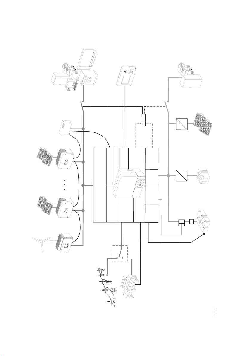
You can use the Sunny Island within various system configurations.
• The graphic on the following page shows which components can be integrated into a standalone grid system.
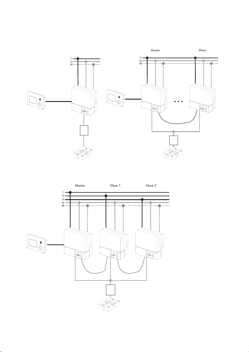
• The graphics on the page after next show the different wiring options (1-phase, 1-phase
parallel and 3-phase).
Technical Description SI2012_2224-TEN082311 13
Page 14
System Overview SMA Solar Technology AG
DC-Loads
Loads
Sunny Remote Control 1
Charge
controller
POWER
SYSTEM
REPORT
MEMORY
SMACOM
NETCOM
USBCOM
Sunny
WebBox
*)
=
=
PV x
PV
Sunny Boy
Com IN
Com OUT
Display
Relay1/2
BatVtgOut
DC
DC/DC
Charger
=
=
Fuel Cell
BatCur
PV 1
AC1 (Loads/Sunny Boys)
Battery
DigIn
BatTmp
Relay1/2
AC2
(Gen/Grid)
current sensor
Battery
DC-Fuse
Windy Boy Sunny Boy
Battery
temperature sensor
Public grid
Generator
Control voltage
Description
14 SI2012_2224-TEN082311 Technical Description
*) DC-supply contactor (not included in delivery)
Page 15
SMA Solar Technology AG System Overview
1-phasig 1-phasig parallel
3-phasig
Technical Description SI2012_2224-TEN082311 15
Page 16
Safety Instructions SMA Solar Technology AG
3 Safety Instructions
Please follow all operating and safety instructions in this manual. Failure to follow these instructions
could result in damage to the device and personal hazard.
DANGER!
Risk of lethal electric shock when opening the devices.
• Installation and repair of the devices in the stand-alone grid system must be carried
out exclusively by qualified personnel.
• Observe all provisions and safety notices.
• Before starting work disconnect all live components by using circuit breakers.
• Secure circuit breakers against accidental switching on.
Information
Be sure to observe all applicable regional standards and guidelines.
16 SI2012_2224-TEN082311 Technical Description
Page 17
SMA Solar Technology AG Unpacking
4 Unpacking
Before installing the Sunny Island and the Sunny Remote Control 1, make sure that all parts are
included in the delivery.
• Carefully check the packaging and the devices for any signs of damage.
• Ensure that all parts are included in the delivery (see section
4.1 "Scope of delivery" (Page 18)).
If something is missing or if the devices have been damaged during shipment, contact the SMA
Solar Technology AG immediately. Further information is provided in
section .21 "Contact" (Page 201).
Information
Keep the packaging in case you need to return the Sunny Island, the Sunny Remote
Control 1 or their accessories.
Technical Description SI2012_2224-TEN082311 17
Page 18
Unpacking SMA Solar Technology AG
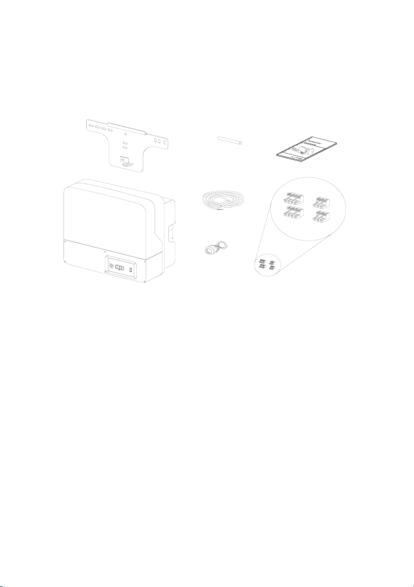
4.1 Scope of delivery
4.1.1 Sunny Island 2012/2224
The following elements are included:
G
F
B
A
C
H
A 1 Sunny Island 2012/2224 and lid.
B 1 Wall bracket
C 1 Battery temperature sensor
D 2 3-pin print terminals (for connecting relays 1 & 2)
E 2 4-pole print terminals for connecting battery temperature sensors
F 1 silicone tube 10 mm x 0.5 m
G 1 Technical Description (Manual)
H 1 M25 metric-thread cable screw
2x E
2x D
18 SI2012_2224-TEN082311 Technical Description
Page 19
SMA Solar Technology AG Unpacking
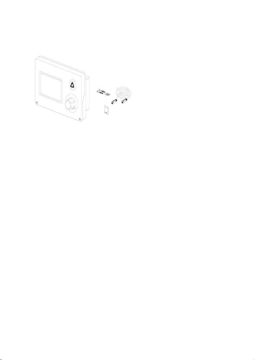
4.1.2 Sunny Remote Control 1
The following elements are included:
A
B
C
D
A 1 Sunny Remote Control 1 (SRC-1)
B 2 Screws and dowels
C 1 CAT5e-FTP patch cables (2 x RJ45 plugs, 5 m)
D1MMC/SD card
Technical Description SI2012_2224-TEN082311 19
Page 20
Unpacking SMA Solar Technology AG
4.2 Name Plate/Firmware Version
4.2.1 Sunny Island 2012/2224
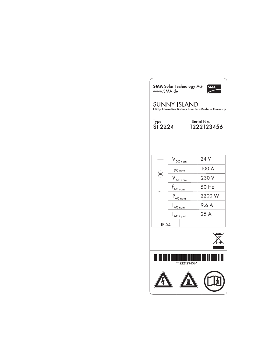
You can identify the Sunny Island by the type plate and firmware version. The following diagram
shows the type plate of the Sunny Island 2224.
• The name plate is located outside on the right side
of the housing.
• You can read the the firmware version of your
device on the display using the "331.02 FwVer"
parameter (see section
17.3 "Diagnosis" (Page 178).
20 SI2012_2224-TEN082311 Technical Description
Page 21
SMA Solar Technology AG Unpacking
4.2.2 Sunny Remote Control 1
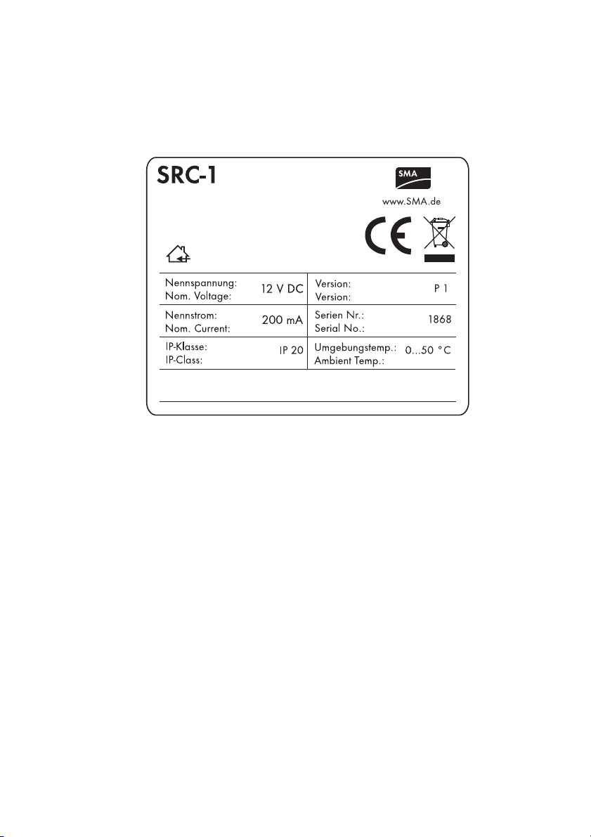
You can identify the display by the name plate. The type plate is located on the rear side of the
Sunny Remote Control 1.
.
Technical Description SI2012_2224-TEN082311 21
Page 22

Installation SMA Solar Technology AG
5 Installation
Take note of the required installation conditions specified in the sections below before mounting,
installing and commissioning the Sunny Island.
5.1 Required Tools and Resources
The following tools and materials are recommended for mounting and installing the island grid
system:
Tools (not included in delivery)
Stripping pliers
Drill (e.g. stone drill), Ø 6 to 10 mm
Drill
Crimping tool for cable lug
Torque wrench (4 Nm to 10 Nm), 13 mm socket wrench
4 mm allen wrench
Cable knife
Ratchet (including extension)
Combination pliers
13 mm open end/ring wrench
Multimeter
Diagonal cutting pliers
Phillips screwdriver, PH1and PH2
Flathead screwdriver, 0.4 x 2.5 mm/1.0 x 10 mm/1.0 x 5.5 mm
Spirit level
Material (not included in delivery)
Cable end sleeves
Wall anchors for the wall bracket (e.g. SX 10)
Cable ties
AC cable (3 leads, 2.5 mm² each)
DC cable (95 mm² max.)
Cable lug for DC cable
hexagon bolts, 8x60 mm, washers
22 SI2012_2224-TEN082311 Technical Description
Page 23
SMA Solar Technology AG Installation
Material (not included in delivery)
Heat shrink tubing
5.2 Sunny Island 2012/2224
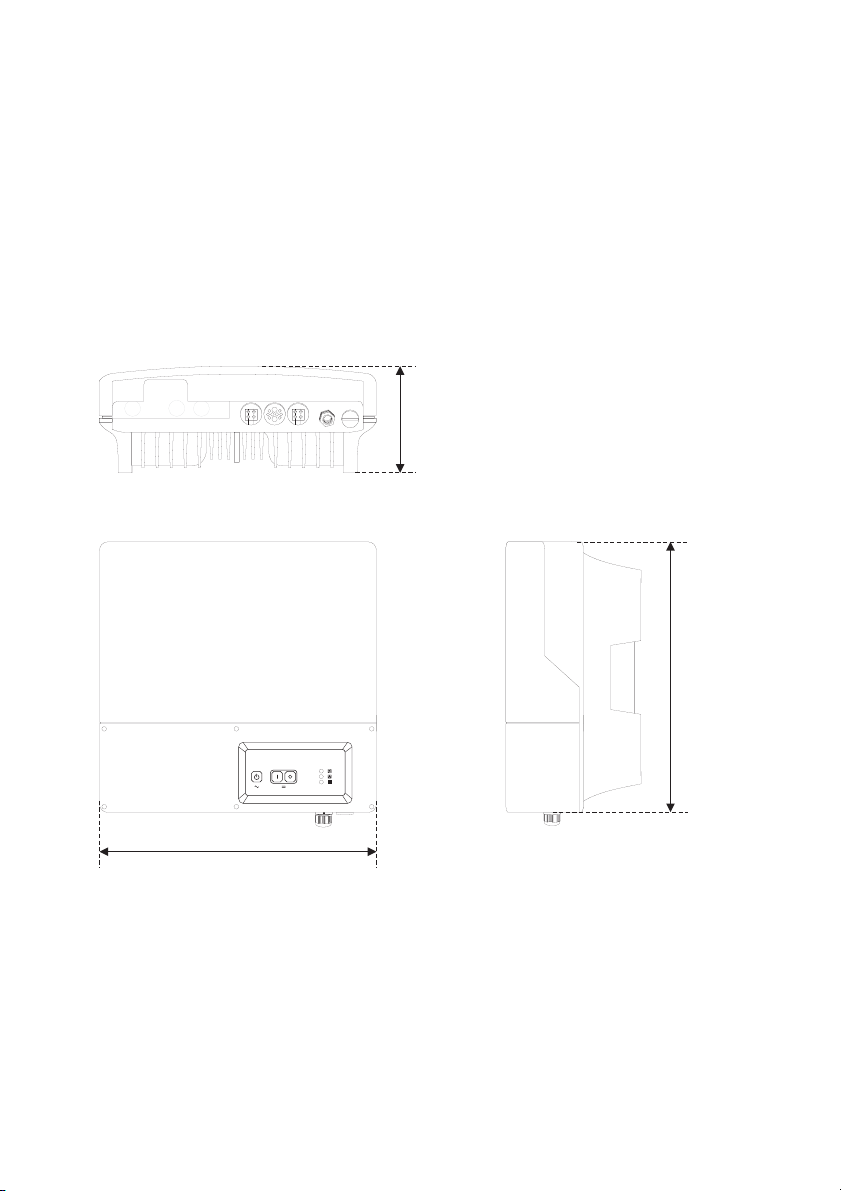
5.2.1 Dimensions
Housing:
185 mm
445 mm
470 mm
Technical Description SI2012_2224-TEN082311 23
Page 24
Installation SMA Solar Technology AG
5.2.2 Choosing a Mounting Location
DANGER!
Death hazard due to fire or explosions
The temperature of the enclosure can reach 60 C during operation.
Do not install the device
• on flammable construction materials,
• in areas where highly flammable materials are stored,
• in potentially explosive areas
CAUTION!
Touching these parts could result in severe burns.
The temperature of the enclosure can reach 60 C during operation.
• Mount the device in such a way that it cannot be touched inadvertently!
• The location for the installation must be suitable for the weight (ca. 18 kg) and the size.
• Choose a solid fundament for mounting.
• The installation location must be accessible at all times (do not mount in inaccessible places).
• An ambient temperature of between -25 °C to +60 °C guarantees optimal operation.
• Avoid direct solar radiation. Excessive heating could lead to a reduction in performance.
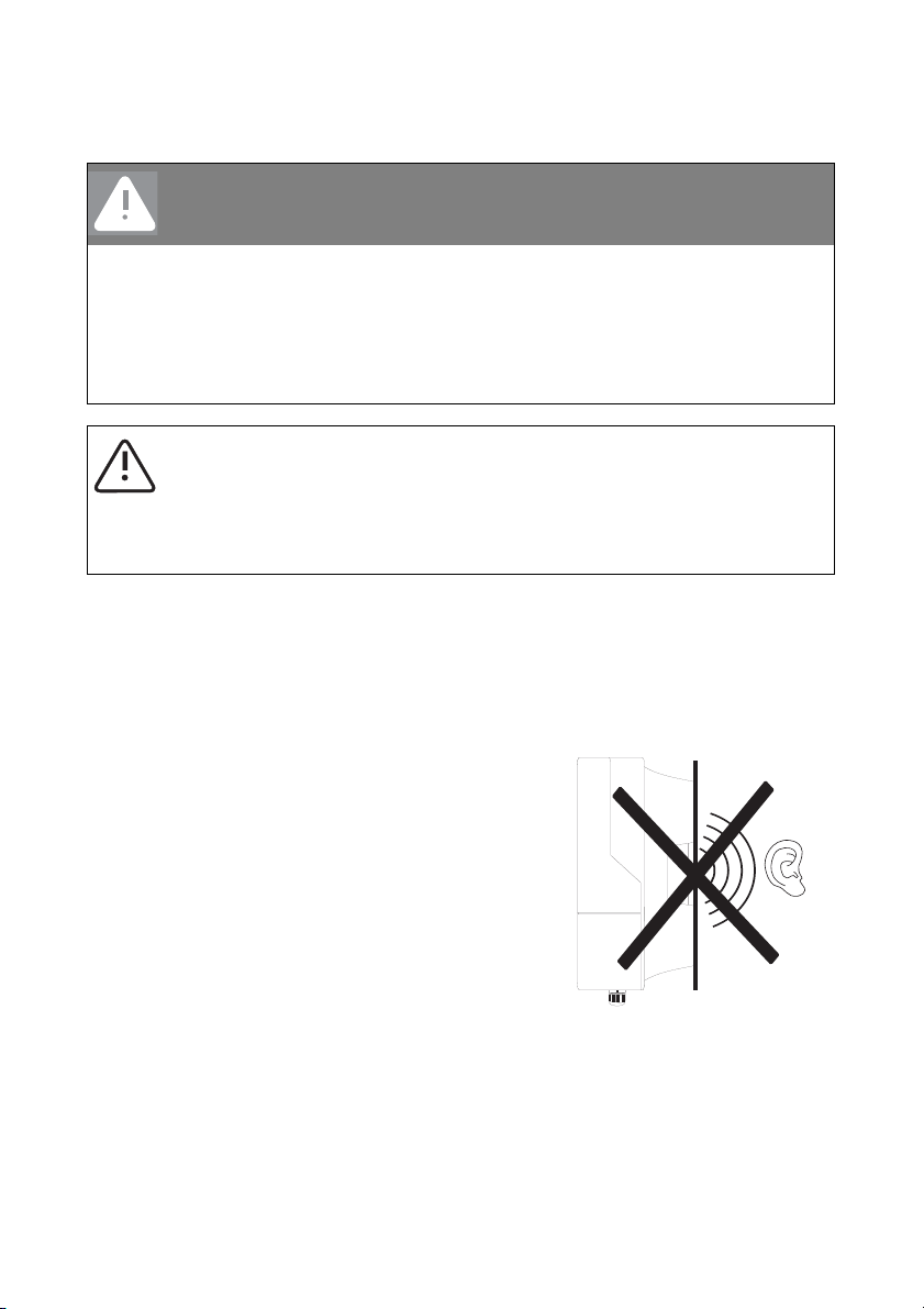
• In domestic installations, the unit should not be
mounted on plasterboard walls or similar materials in
order to avoid audible vibrations.
The Sunny Island can make noises when in use that
may be irritating in a domestic setting.
24 SI2012_2224-TEN082311 Technical Description
Page 25
SMA Solar Technology AG Installation
5.2.3 Observe minimum clearances
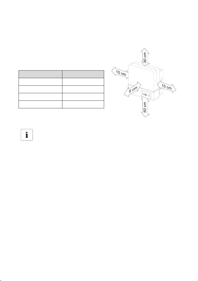
The following minimum clearances to walls, other devices or objects must be observed to guarantee
sufficient heat dissipation.
All external cables are connected through the
underside of the housing. This requires a minimum
clearance of at least 50 cm.
Direction Minimum clearance
sides 10 cm
above 30 cm
below 50 cm
in front 5 cm
Sufficient Ventilation
When installing the in smaller rooms, make sure that adequate ventilation is available.
During operation the device produces heat which must be dissipated.
Technical Description SI2012_2224-TEN082311 25
Page 26
Installation SMA Solar Technology AG
5.2.4 Mounting Position
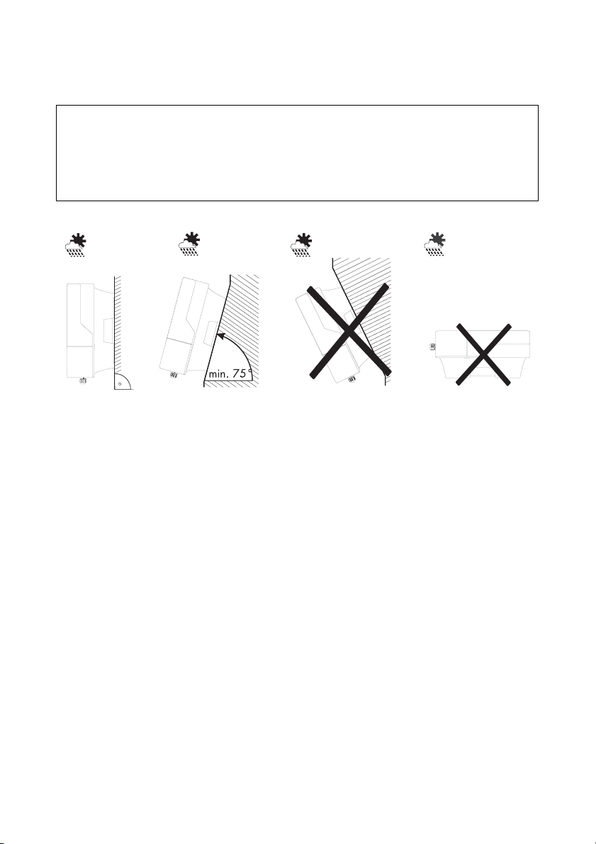
NOTICE!
Short-circuit due to condensation
If the device is in operation while lying flat, water can accumulate due to condensation.
• Operate the device only while it hangs vertically on a wall.
• Mount the device only vertically or with a backward inclination of at most 15°!
• Do not mount the device with a forward inclination!
• Do not mount the device lying flat on its back!
• Mount the device at eye level.
26 SI2012_2224-TEN082311 Technical Description
Page 27
SMA Solar Technology AG Installation
5.2.5 Mounting the Sunny Island with a Wall Mounting Bracket
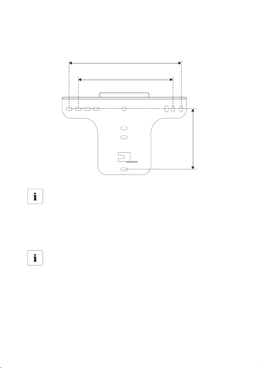
1. Use the wall bracket as a drilling template.
.
315.9 mm
260 mm
170 mm
Number of drilled holes used
• When mounting onto a wall, use at least two of the horizontal holes and the lowest
one in the middle.
• When mounting onto a post use at least three of the holes in the middle (use the
superior one in any case).
Mounting Material
When mounting the wall bracket use mounting material which is suited to the fundament.
In doing this, observe that the weight of the Sunny Island is approximately 18 kg.
Technical Description SI2012_2224-TEN082311 27
Page 28
Installation SMA Solar Technology AG
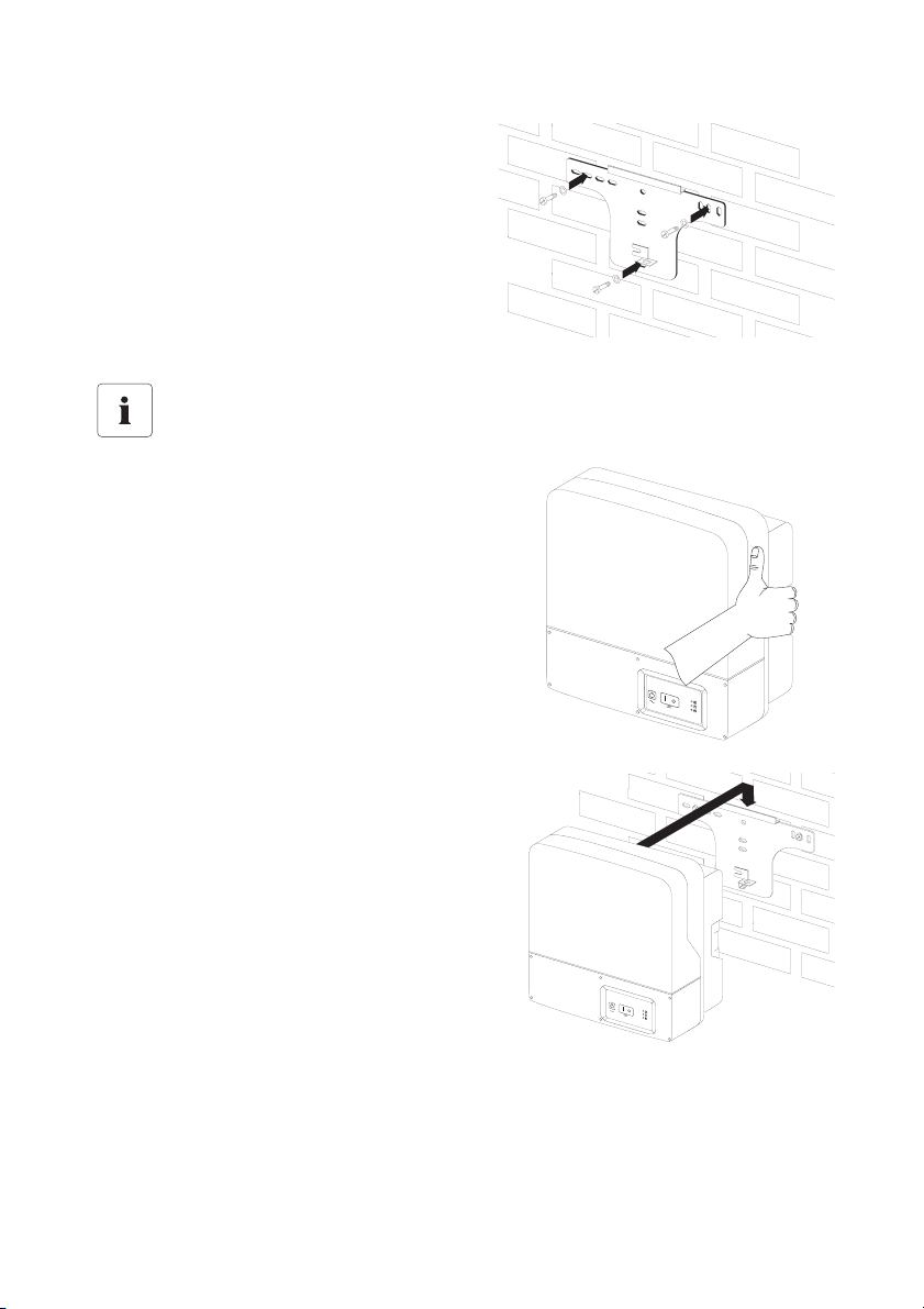
2. Mount the wall bracket.
Transporting the Sunny Central
For the transportation and the installation
of the Sunny Island use the handles at the
sides of its enclosure.
3. Hang the device onto the wall bracket with its
attachment plate somewhat displaced to the
left.
The right edge of the back side of the device
must be flush with the right edge of the wall
bracket.
28 SI2012_2224-TEN082311 Technical Description
Page 29
SMA Solar Technology AG Installation
4. Check on both sides to see that the device sits
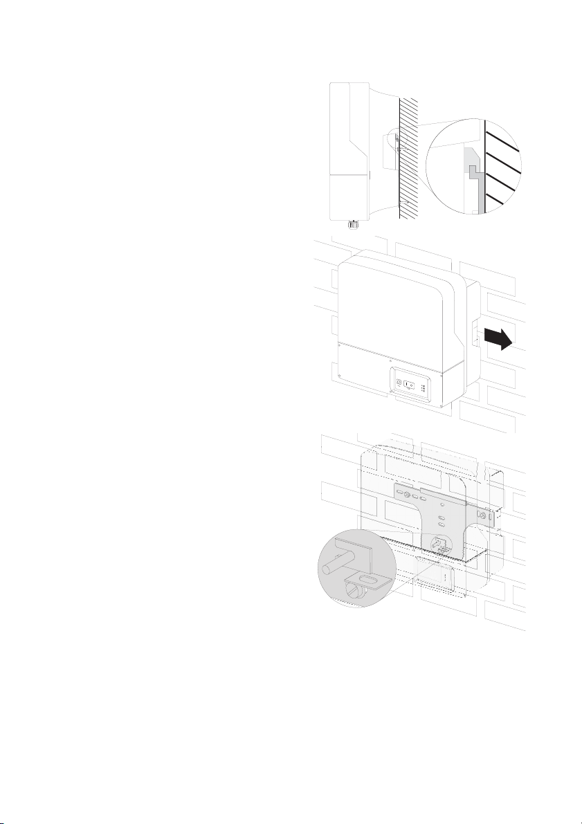
correctly.
5. Secure the enclosure so it cannot be
accidentally lifted up.
Shove the Sunny Island toward the right on the
wall bracket until it snaps into place with the
safety stud on its back side.
6. Check to see that the device sits correctly.
Technical Description SI2012_2224-TEN082311 29
Page 30
Installation SMA Solar Technology AG
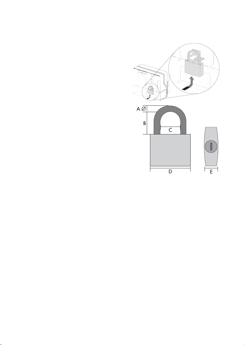
Optional anti-theft protection
Protect the device against theft. Secure the Sunny
Island with a lock onto the wall mounting bracket.
The lock must meet the following specifications:
•Size:
A: 6 mm - 10 mm in diameter
B: 21 mm - 35 mm
C: 20 mm – 33 mm
D: 40 mm – 60 mm
E: 13 mm – 21 mm
•stainless
• hardened shackle
• secured cylinder lock
30 SI2012_2224-TEN082311 Technical Description
Page 31
SMA Solar Technology AG Installation
5.3 Sunny Remote Control 1
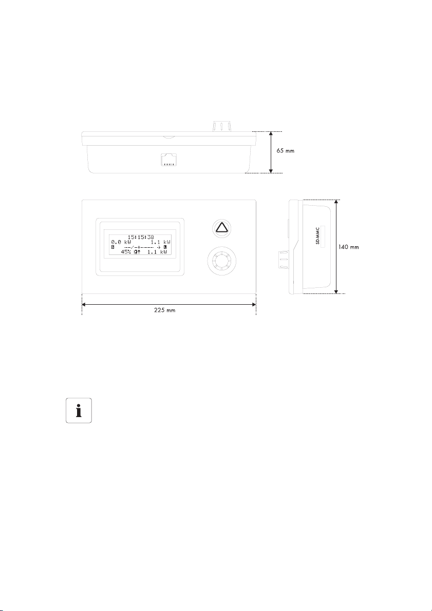
5.3.1 Dimensions
The external display has the following dimensions:
5.3.2 Choosing a Mounting Location
• The installation location must be easily accessible.
Using the display, you can control the Sunny Island and with it the island grid system.
Distance between the Sunny Remote Control 1 and the Sunny Island
The communication cable between the Sunny Island the Sunny Remote Control 1
must not exceed 20 m in length.
• Choose a solid fundament for mounting.
• Protect the Sunny Remote Control 1 from dust, wet conditions, corrosive substances and
vapors.
• An ambient temperature of between 0 °C to 50 °C guarantees optimal operation.
• Avoid direct solar radiation.
Technical Description SI2012_2224-TEN082311 31
Page 32
Installation SMA Solar Technology AG
5.3.3 Wall Mounting
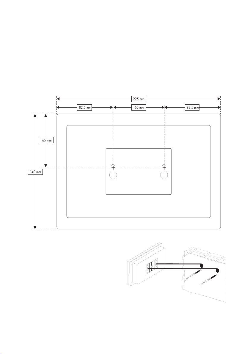
Mount the Sunny Remote Control 1 on the wall. Proceed as follows:
1. Allow enough room for installing a communications cable and a MMC/SD card.
2. Determine the position of the two holes to be drilled using the Sunny Remote Control's
mounting plate.
To do this, unscrew and remove the mounting plate from the back of the Sunny Remote
Control.
3. Draw the position of the holes to be drilled.
4. Install the dowels and screws included.
5. Install the dowels and screws included
Allow for the heads of the screws to
protrude about 6 mm from the surface of
the wall.
6. Screw the mounting plate onto the Sunny
Remote Control enclosure.
7. Hang the Sunny Remote Control onto the
screws.
8. Check to see it sits correctly.
32 SI2012_2224-TEN082311 Technical Description
Page 33
SMA Solar Technology AG Installation
5.4 Installing Batteries
Information
Observe the battery manufacturer's installation instructions, as provided with the battery
upon delivery, and the applicable standards and directives for installation of batteries
(EN 50272-2).
DANGER!
Death hazard due to
1. Explosion and fire
2. short circuit
3. Chemical burns due to leaking electrolytes
1. Smoking prohibited!
Do not allow open flames, embers, or sparks near the battery.
2. The metal parts of the battery carry voltages.
Do not place foreign objects or tools on the batteries!
Work on the battery with insulated tools exclusively!
3. Use protective clothing and eyewear when working on the battery.
4. During normal operation, it is not possible to accidentally touch the electrolyte.
Do not damage the enclosure of the battery! The electrolyte is extremely corrosive.
Dimensioning for the Battery Capacity
To ensure a faultless operation of the island grid system, the SMA Solar Technology AG
recommends a battery capacity of at least:
• 175 Ah per Sunny Island 2224 (24 V) at C
• 350 Ah per Sunny Island 2012 (12 V) at C
10
10
If an AC-coupled PV plant is to be connected to the system, the SMA Solar Technology
AG recommends a battery capacity of at least:
• 200 Ah (C
) per kW of AC nominal power of the Sunny Boy inverter in the case
10
of 24 V systems.
• 400 Ah (C10) per kW of AC nominal power of the Sunny Boy inverter in the case
of 12 V systems.
Technical Description SI2012_2224-TEN082311 33
Page 34

Installation SMA Solar Technology AG
Batteries must be accommodated in protected rooms, and sufficient ventilation of the installation
location must be ensured. In the case of batteries which are connected to one Sunny Island
exclusively, there is no need for protection against direct or indirect contact, due to the safety lowvoltage.
It is not necessary to install such batteries in a separate battery room, or in a self-contained electrical
facility.
The necessary air volume flow for ventilation of the room which accommodates the batteries is
calculated as per EN 50272-2 as follows:
Q = 0,05 * n * I
* C10/100 [m³/h]
Gas
Q = required air flow volume
n = Number of cells
I
= maximal finishing charge rate
Gas
with C10 as the 10 hour nominal capacity in [Ah].
The cross-sectional area of the ventilation inlets and outlets (in the case of natural ventilation) is
calculated according to the following formula:
A = 28 * Q [cm
2
]
Sufficient dissipation of explosive gases is not always ensured in the vicinity of the battery. Therefore,
a safety distance must be observed, in the form of an air clearance in which no sparks or smoldering
materials are allowed.
The clearance distance is calculated as follows:
d = 5,76 * (C10)
1/3
[cm]
Installation of a battery with liquid eletrolyte.
With closed batteries, installation in an acid-resistant collecting tray is to be provided for
so that, in the event of a fault, leaking electrolyte cannot cause further damage.
Finally, install the battery bank in accordance with the installation instructions provided by the
battery manufacturer.
34 SI2012_2224-TEN082311 Technical Description
Page 35
SMA Solar Technology AG Installation
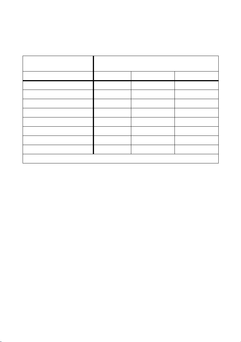
Refer to the following table for the preferred values for the finishing charge rates and charge
voltages for the battery types which may be used in the system, unless the battery manufacturer has
determined other values:
Maximal charging voltage in
[V/cell]
maximal finishing charge rate I
in [A/100 Ah]
Gas
Type FLA* VRLA NiCd
1.4 - - 0.5
1.55 - - 5
1.6 - - 5
1.65 - - 5
2.25 0.5 0.1 -
2.4 2 0.8 -
2.5 4 1.5 -
2.6 6 6 -
*These values are valid only for battery types with low antimony content (SB < 3 %)
Consult the appropriate battery manufacturer for other battery type values.
Technical Description SI2012_2224-TEN082311 35
Page 36
Opening and Closing SMA Solar Technology AG
6 Opening and Closing
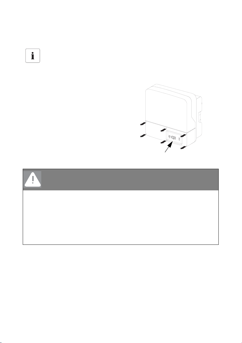
Enclosure lid
Only remove the lower enclosure lid from the Sunny Island when you want to mount,
install or maintain it.
- A = upper enclosure cover
- B = lower enclosure cover
- C = control area
DANGER!
Risk of lethal electric shock
A
B
C
High voltages are present in the device!
• Only qualified personnel should open the device!
• Do not open the lower enclosure cover!
After the system has been disconnected (see chapter 10.1.4 "Disconnecting the
Device from Voltage Sources" (Page 87)) there are still dangerous voltages present
for up to 15 minutes.
• Follow the instructions!
1. Shut down the Sunny Island.
2. Disconnect the Sunny Island from all voltage sources (battery, generator, grid). (see chapter
10.1.2 "Stopping" (Page 85) and 10.1.3 "Switching Off" (Page 87)).
3. Ensure that the system cannot be accidentally switched on again.
36 SI2012_2224-TEN082311 Technical Description
Page 37
SMA Solar Technology AG Opening and Closing
6.1 Opening the Sunny Island
NOTICE!
The components in the Sunny Island (e.g., communications interface) can be
damaged by an electrostatic discharge!
• When working on the Sunny Island and when handling the components observe all
ESD safety regulations.
• Eliminate static charge by touching the grounded metal casing.
• Only then should you begin any work.
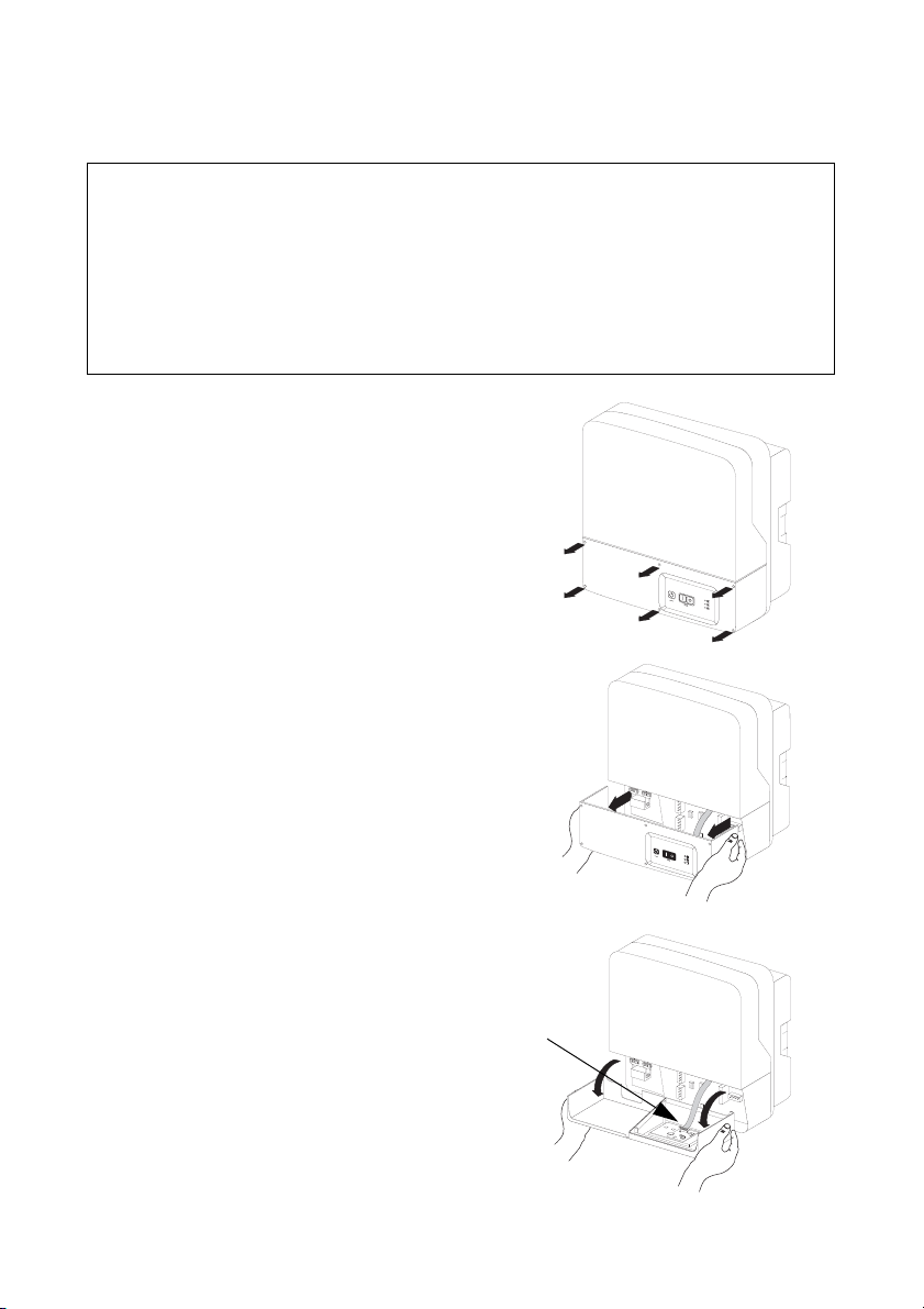
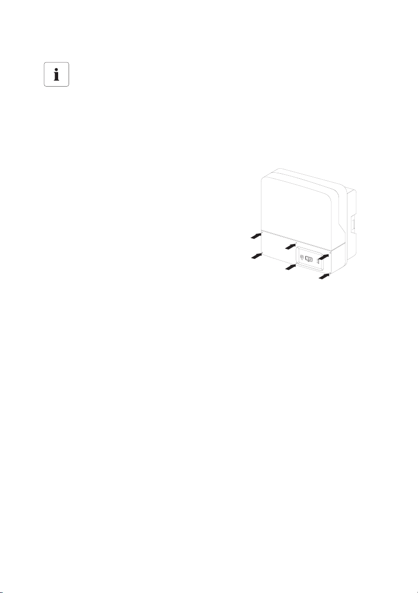
1. Loosen the six non-removable allen screws on the
lower cover (B).
B
2. Remove the cover carefully.
3. Unplug the control area cable from the inner side
of the enclosure cover (in the new devices the
cable is not in place).
D
4. Keep the cover in a safe place.
Technical Description SI2012_2224-TEN082311 37
Page 38
Opening and Closing SMA Solar Technology AG
Information
The cover screws can be loosened but not removed, which keeps them from getting lost.
6.2 Closing the Sunny Island
1. Ensure that all cables are properly laid and that all tools have been removed from within the
Sunny Island's enclosure (see chapter 7 "Sunny Island Electrical Connection" (Page 39)).
2. Plug the cable for the control area into the lower
enclosure cover.
3. Starting from the front, place the cover evenly on
the housing.
4. Screw all six screws in sequence and lightly into
their threads (one or two turns).
5. Tighten the screws in a crosswise sequence and
with 2.5 Nm of torque.
38 SI2012_2224-TEN082311 Technical Description
Page 39
SMA Solar Technology AG Sunny Island Electrical Connection
7 Sunny Island Electrical Connection
DANGER!
Risk of lethal electric shock due to wrong connection
• Only qualified personnel should install the devices' connections.
• Install line safety switches (max. 25 A) before the Sunny Island as seen from the grid
side.
• Follow every safety notice in this chapter during installation.
NOTICE!
The components in the Sunny Island (e.g., communications interface) can be
damaged by an electrostatic discharge!
• When working on the Sunny Island and when handling the components observe all
ESD safety regulations.
• Eliminate static charge by touching the grounded metal casing.
• Only then should you begin any work.
Technical Description SI2012_2224-TEN082311 39
Page 40
Sunny Island Electrical Connection SMA Solar Technology AG
7.1 At a Glance
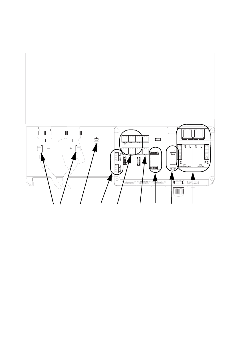
The following figure provides an overview of all connections of the Sunny Island:
BA
C
D
F
E
G
H
A DC connections
B Additional protective earth conductor
C Additional connection terminals (battery current sensor, battery temperature
sensor, etc.)
D Communication connection
E Sunny Remote Control connection
F Interface plug (Piggy Back) RS485
G Multi-function relay connections
H AC connections
40 SI2012_2224-TEN082311 Technical Description
Page 41
SMA Solar Technology AG Sunny Island Electrical Connection
Cable conduits in the enclosure.
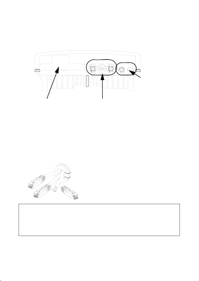
All cables are fed through the feed-troughs on the bottom side of the device (see following figure)
and connected to the appropriate connection terminals on the Sunny Island.
Cable screw joint with
metric thread
DC cable insertion
Cable conduit gasket
point
Cable screw joint with metric thread
Use the metric-thread cable screw connections provided to fasten the AC cables inside the Sunny
Island housing in a manner conforming to the appropriate norms. The metric-thread cable screw
connections guarantee a dust-free and waterproof installation of the cables in the housing and also
provide strain relief for the cable connection.
Close all unused openings in the housing using the appropriate dummy plugs.
Cable conduit gasket
The cable conduit gasket allows simple connection of the
pre-assembled communication and control cables (with
RJ45 plugs).
NOTICE!
Damage to device can be caused by penetrating moisture
• Install screw joints and cable conduit gaskets properly.
• Seal unused conduits.
Properly installed screw joints and cable conduit gaskets guarantee to provide protection rating
IP54.
Technical Description SI2012_2224-TEN082311 41
Page 42

Sunny Island Electrical Connection SMA Solar Technology AG
Obtain an overview of the different components and connection areas of the Sunny Island (see
section 7.1 "At a Glance" (Page 40)).
Detailed installation descriptions of the connections are provided in the following sections:
- DC connection Chapter 7.2 "DC connection" (Page 43)
- AC connection Chapter 7.3 "AC Connection" (Page 46)
- Grounding: Chapter 7.3.1 "Grounding" (Page 47)
- Sunny Remote Control 1 Chapter 7.4 "Sunny Remote Control 1" (Page 51)
- External communication: Chapter 7.5 "Communication" (Page 53)
- Battery temperature sensor: Chapter 7.6.1 "Battery Temperature Sensor" (Page 59)
- Multi-function Relays 1 and 2 Chapter 7.6.3 "Multi-function Relays 1 and 2" (Page 63)
42 SI2012_2224-TEN082311 Technical Description
Page 43
SMA Solar Technology AG Sunny Island Electrical Connection
7.2 DC connection
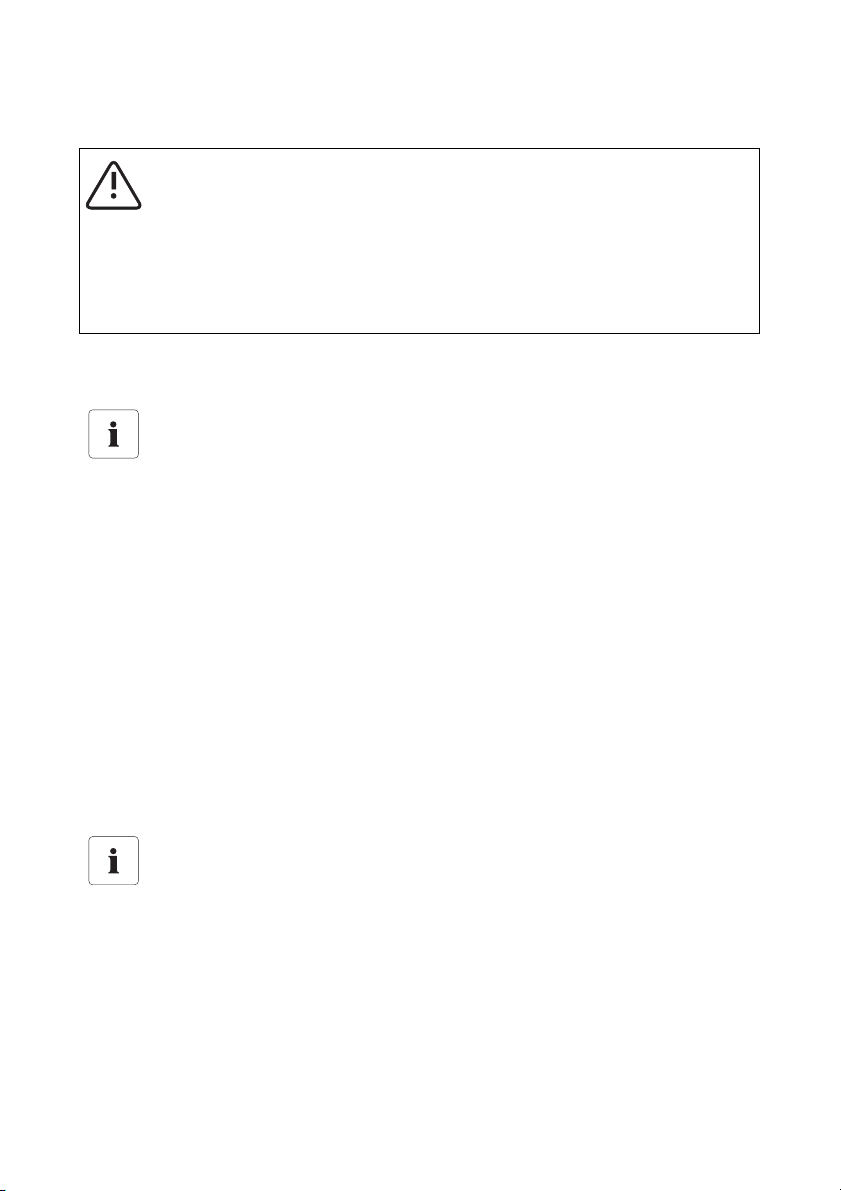
WARNING!
The Sunny Island 2012 / 2224 has no internal DC fuse.
Install an external DC fuse between the Sunny Island and the battery as a protective
conductor. Dimension the fuse in proportion to the cable cross-section used.
• Sunny Island 2012: fuse NH01, 250 A (BATFUSE-B.0x)
• Sunny Island 2224: fuse NH00, 125 A (BATFUSE-A.0x)
7.2.1 Grounding
External grounding.
• External grounding of the negative pole of the batteries is possible, because the
batteries and the grid side are galvanically isolated within the Sunny Island. In this
case, make sure that the high currents that may occur under fault conditions can be
adequately diverted.
• If a connection is required, then this must be made separately, external to the Sunny
Island, by an installer.
• When grounding the battery, the Sunny Island's enclosure must be additionally
grounded, also in the DC area (see chapter 7.3.1 "Grounding" (Page 47)).
Calculating the Required Grounding Conductor Cross-Section
The SMA Solar Technology AG cannot state generally valid values for the cross-section of the
conductor required for the external grounding of the battery. The conductor dimensions depend on
the type and size of the battery connected, the external fuse (DC side) and the material used for the
grounding conductor.
Determining the wire cross-section
Exact calculation of the grounding conductor cross-section must consider the regionally
applicable standards and guidelines (e.g., DIN VDE 0100 Part 540).
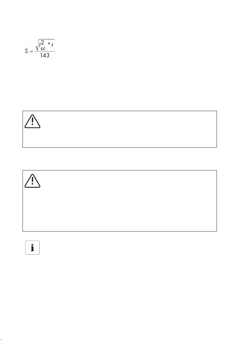
The required cross-section of a (copper) grounding conductor can be calculated using the following
formula. Trigger times, e.g., for the integrated DC circuit breaker and short-circuit currents of
between 2000 and 10,000, are typically about 25 ms.
Technical Description SI2012_2224-TEN082311 43
Page 44
Sunny Island Electrical Connection SMA Solar Technology AG
t = disconnection time in seconds
= max. battery current (short circuit) in Amperes
I
SC
S = cross section of the conductor in mm²
A grounding conductor of 10,000 mm² cross-section is thus adequate for short-circuit currents up to
16 A.
7.2.2 Connecting the Battery
Connect a suitable battery to the DC side (see section 20 "Technical Data" (Page 197)).
WARNING!
Risk of lethal electric shock when the battery is connected!
Connect the NH fuse to the BatFuse-A.01 bracket or close the DC fuse disconnector only
after completing all installation work on the island grid system.
The DC connection must be made observing all valid regulations (e.g., DIN EN 50272-2, "Safety
requirements for Batteries and Battery Systems - Part 2: Stationary Batteries").
WARNING!
Danger of burns or even death due to arcing and short-circuiting when
connecting the battery.
• All safety and maintenance instructions provided by the battery manufacturer must
be heeded.
• Use special (insulated) tools to mount and install the battery.
• Please observe the correct cross-section and polarity of the leads connected to the
battery.
DC Cables
The DC cables should be as short as possible (in any case < 30 m). Long cables and
insufficient cable cross-sections reduce the system efficiency as well as the overload
capabilities. Do not lay the battery feed cables under plaster or in armored plastic pipes.
High currents flow through the battery cables, so they can become very warm.
44 SI2012_2224-TEN082311 Technical Description
Page 45
SMA Solar Technology AG Sunny Island Electrical Connection
7.2.3 Connecting the Sunny Island
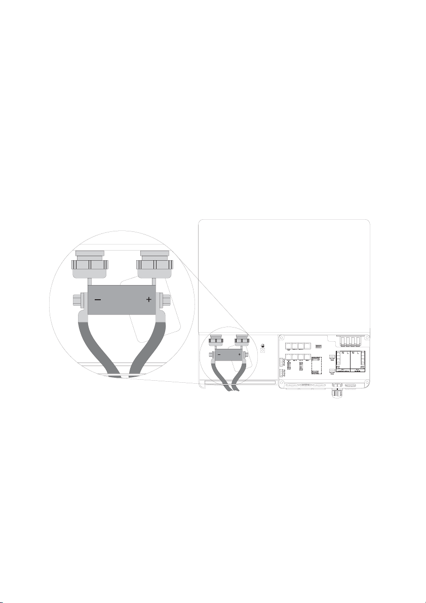
There is a "DC —" and a "DC +" connection provided for each ring cable lug (max. 95 mm²) for the
battery feed cables in the Sunny Island.
The following cable cross-sections are recommended for the DC cables:
Sunny Island 2224: 35 mm² min.
95 mm² max.
Sunny Island 2012: 70 mm² min.
95 mm² max.
Install the DC connections in the following sequence:
1. Remove the protective insulation from each DC cable.
2. Fit the bare cable ends with ringed cable lugs.
3. Introduce the DC cables into the enclosure from below and to the left.
4. Attach the "DC —" conductor with the ring cable lug to the "DC —" connection and tighten the
retaining screw firmly (torque 4.0 Nm to 10 Nm).
5. Then attach the "DC +" conductor with the ring cable lug to the "DC +" connection and tighten
the retaining screw firmly (torque 4.0 Nm to 10 Nm).
Technical Description SI2012_2224-TEN082311 45
Page 46
Sunny Island Electrical Connection SMA Solar Technology AG
7.3 AC Connection
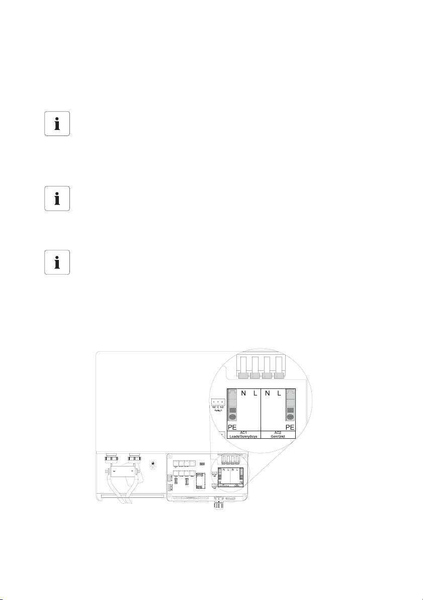
Connect the Sunny Island through a sub-distribution to the inland grid (loads, PV generator (Sunny
Boy)) and to any other external sources (generator, grid).
Information
The sub-distribution unit must be equipped with appropriate circuit breakers. Be sure to
observe all the applicable regional standards and guidelines.
Information
A maximum of 25 A should flow through the Sunny Island's AC input.
Information
The Sunny Island does not disconnect all 3 poles: the neutral conductor (N conductor) is
looped through the device; i.e., the AC1 and AC2 N connection terminals are connected
inside the device.
Use a maximum cross-section of 6 mm² for the AC installation. The nominal AC current is 9.6 A.
46 SI2012_2224-TEN082311 Technical Description
Page 47
SMA Solar Technology AG Sunny Island Electrical Connection
7.3.1 Grounding
Information
In stand-alone configurations, the (protective) ground of the Sunny Island and its
individual components must be wired as a TN grid only. All valid standards and
guidelines must be taken into account!
CAUTION!
Danger of injury due to leakage current against PE.
The N connection of the Sunny Island has NOT been connected with PE by default.
• Ground the island grid system outside the Sunny Island before commissioning (see
chapter 7.3.3 "AC2 (Gen/Grid)" (Page 50)).
• For safety technical reasons (leakage currents of over 3.5 mA),
- two protective ground wires with 6 mm² (double ground) or
- one protective ground wire >10 mm².
For the ground connection with two redundant protective leads use the PE connections in the AC
connection area of the Sunny Island.
For the ground connection with the protective lead of > 10 mm² use the addtional PE connection
(PE crown on the enclosure) in the DC connection area (see following segment).
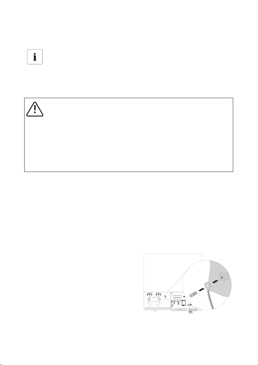
Additional Grounding of the Housing.
If the Sunny Island is used in a country which prescribes the use of a second protective ground (e.g.,
Switzerland), you can ground the enclosure additionally by using the PE crown in the DC
connection area.
Proceed as follows:
1. Strip the protective conductor.
2. Fit the protective conductor with a ringed cable
lug (max. cross-section 50 mm²).
3. Screw the ringed cable lug onto the enclosure's
PE crown (screw: M8 x 20 mm).
Technical Description SI2012_2224-TEN082311 47
Page 48
Sunny Island Electrical Connection SMA Solar Technology AG
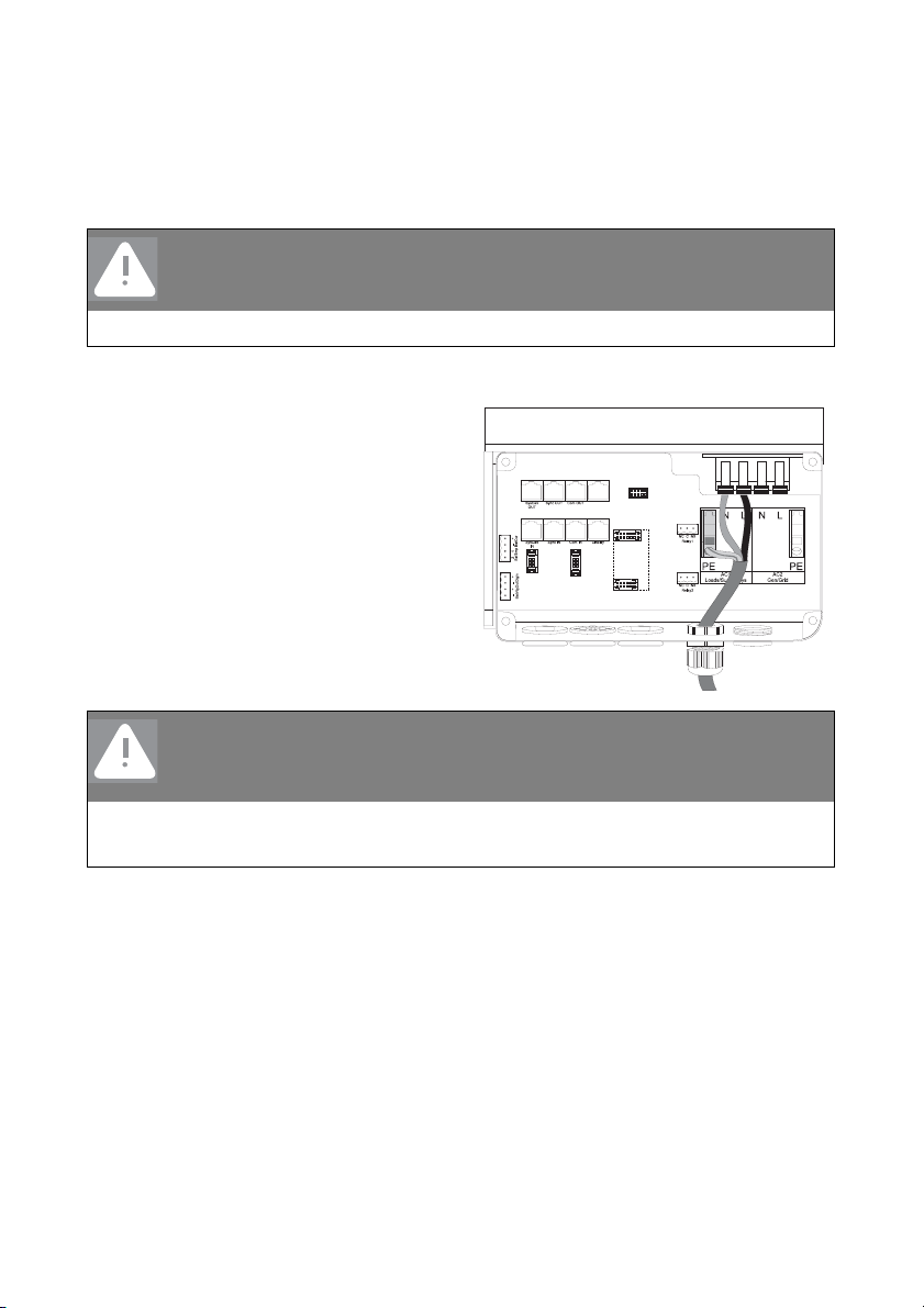
7.3.2 AC1 (Loads/Sunny Boys)
Connect, with three conductors via the subdistribution, for example, loads, PV generators (Sunny
Boy) and wind power plants (Windy Boy), to the Sunny Island's AC1 connection.
DANGER!
Death hazard due to residual currents
• Install an RCD circuit breaker between the Sunny Island and the loads.
Connection procedure for the Sunny Island:
1. Loosen the metric-threaded cable screw
joint on the right of the enclosure's
underside.
2. Insert the 3-conductor cable through the
threaded joint.
3. Draw the cable into the enclosure.
4. Flip the AC1's terminal connectors (N and
L conductors) all the way up.
DANGER!
Risk of lethal electric shock
Improperly laid cables can loosen out of the terminal connectors.
• Do not use end wire sleeves when connecting the AC cable.
5. Remove the protective insulation from each of the three wires.
48 SI2012_2224-TEN082311 Technical Description
Page 49
SMA Solar Technology AG Sunny Island Electrical Connection
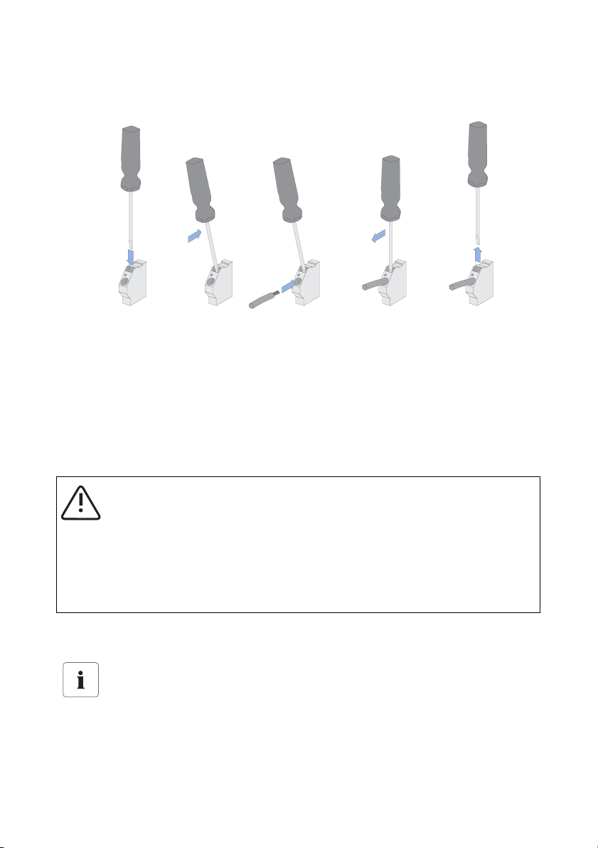
6. Fasten the protective earth (PE) cable onto the spring type terminal. Use a slot screwdriver (see
figure below).
- Stick the screwdriver into the spring type terminal's slit.
- Push the screwdriver upward. The spring type terminal is now open.
- Introduce the stripped PE cable into the terminal (round opening).
- Return the screwdriver to its original position. The spring type terminal is closed and the PE
cable is installed firmly.
7. Connect the N and L cables according to the labeling on the AC1 terminal connectors
"L" and "N" must not be swapped!
CAUTION!
Danger of crushing due to the terminal connectors snapping shut!
When closing, the terminal connectors snap back very fast and with force.
• Flick the clamps back down with care.
• Press down on the clamps with the thumb, and do not take hold of the whole clamp.
• Keep the fingers away from the range of motion of the clamp as it snaps down!
8. Tighten the cable screw joint's lock nut firmly.
Connection in a Single-Phase Parallel System
In a single phase system, connect all Sunny Boys using the same cable cross-sections and
lengths.
Technical Description SI2012_2224-TEN082311 49
Page 50
Sunny Island Electrical Connection SMA Solar Technology AG
Connection in a 3-Phase System
• In a 3-phase system, always connect the master to phase L1, slave 1 to phase L2
and slave 2 to phase L3. This circuitry results in a right rotating field.
• If a phase fails within a three-phase grid, the cluster continues to run. In order to
protect your loads, you may require phase monitoring or a motor overload switch.
7.3.3 AC2 (Gen/Grid)
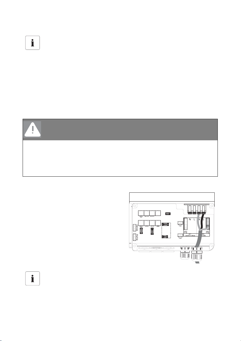
Via the distribution, connect the generator or the public grid using 3 conductors to the Sunny Island's
AC2 connector.
DANGER!
Death hazard due to residual current if the neutral wire is not grounded.
• Do not install an RCD circuit breaker (or similar) onto the island grid system's gridside supply cable.
• Ground the grid-side PEN conductor within the installation (before or at the
separation into N and PE conductors, e.g., the connection from the house's junction
box to the equipotential bonding rail).
Proceed as follows:
1. Remove the blank seals from the opening
on the underside of the enclosure and to
the right.
2. Introduce the metric-threaded cable
connection M25 (included in the delivery)
into the opening and tighten.
Do not forget the seal!
3. Wire up the AC2 cable as described in
chapter 7.3.2 "AC1 (Loads/Sunny Boys)"
(Page 48).
Connection in a Single-Phase Parallel System
• In single-phase parallel systems, connect each of the Sunny Islands via the AC2
terminal to the generator or the public grid.
• The cable cross-sections and cable lengths used must be identical.
50 SI2012_2224-TEN082311 Technical Description
Page 51
SMA Solar Technology AG Sunny Island Electrical Connection
Connection in a 3-Phase System
• In a 3-phase system, always connect the master to phase L1, slave 1 to phase L2
and slave 2 to phase L3. This circuitry results in a right rotating field.
• The system does not monitor additional fuses. Check any additional fuses regularly!
7.4 Sunny Remote Control 1
NOTICE!
The components in the Sunny Island (e.g., communications interface) can be
damaged by an electrostatic discharge!
• When working on the Sunny Island and when handling the components observe all
ESD safety regulations.
• Eliminate static charge by touching the grounded metal casing.
• Only then should you begin any work.
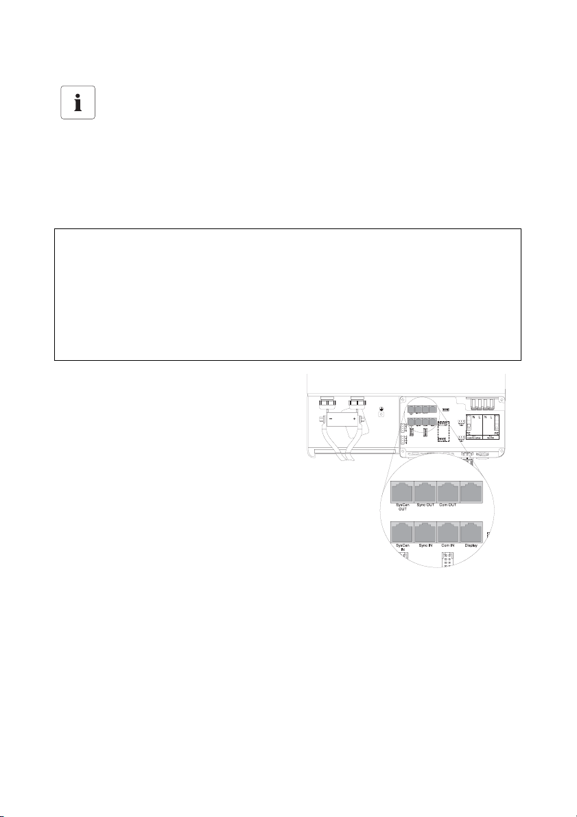
The Sunny Remote Control 1 is connected to the
"Display" terminal in the Sunny Island.
Technical Description SI2012_2224-TEN082311 51
Page 52
Sunny Island Electrical Connection SMA Solar Technology AG
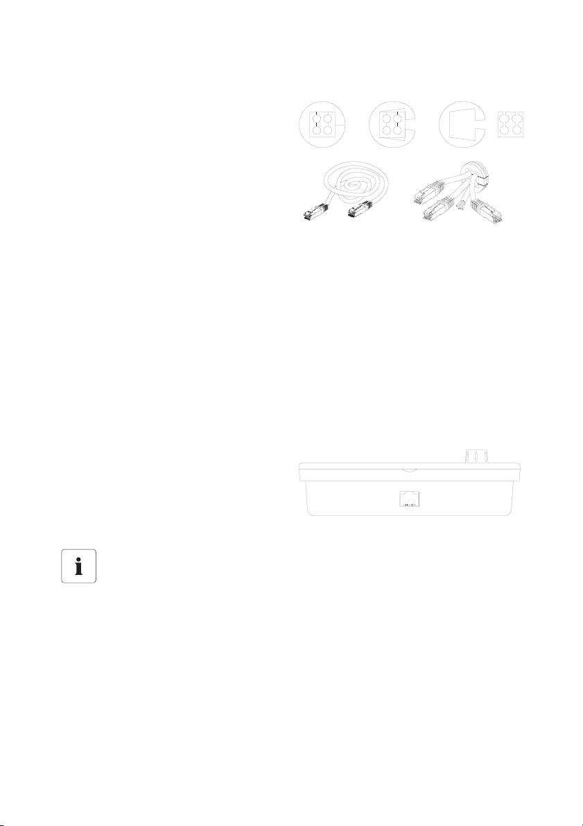
1. Dismantle the preinstalled cable conduit
on the enclosure floor.
2. Remove the feed-through element
completely from the mounting opening.
3. Lay the cable equipped with RJ45 plugs
through one of the openings in the inner
rubber element.
Plan a sufficient lead length from the
enclosure openings to the "Display" socket
on the conductor board.
4. Install all communication leads (see
chapter 7.5 "Communication" (Page 53)),
before you reassemble the rubber element
and refit it onto the Sunny Island.
5. Fit any unused openings on the enclosure
with blind seals.
6. Insert the RJ45 plug into the "Display"
socket in the Sunny Island. The plug snaps
audibly into place.
7. Connect the second RJ45 plug on the
cable (outside the Sunny Island) to the
Sunny Remote Control 1 Display socket.
Information
The communication cable can also be plugged into the Sunny Remote Control during
operation (hotplug-able).
52 SI2012_2224-TEN082311 Technical Description
Page 53
SMA Solar Technology AG Sunny Island Electrical Connection
7.5 Communication
7.5.1 Communication with Sunny Island
The Sunny Island can be connected in parallel or in a 3-phase system with up to two other Sunny
Islands in order to increase the overall power. The devices communicate through CATe-FTP patch
cables (with two RJ45 plugs each). A patch cable is referred to subsequently as a communication
lead.
Notes on the Installation
1. Lay the communication cable separately from the AC cables.
2. DO NOT feed the communication leads through the membranes with their plugs
mounted. Feeding the plugs through the membrane would overstretch it, so that
there would no longer be a tight seal around the cable itself, which is thinner.
3. If the length of the provided communication cables is insufficient, use commercially
available Cat5e FTP cables (single shield) with gold contacts.
4. The maximum cable length is 30 m. The cable cross-section is at least AWG26/7.
Installation in a Single-Phase, Parallel System or in a 3-Phase System
• A communication cable is included with each Sunny Island.
You need the cable in order to establish an (internal) communication between
several Sunny Islands. If you operate only one Sunny Island in the cluster the cable
is not required.
• If needed, choose a parallel/multiphase configuration in the Quick Configuration
Guide (see chapter 9 "(First) Commissioning" (Page 75)).
Install the communication cable as follows:
1. Lay the cable equipped with RJ45 plugs through one of the four openings in the inner rubber
element of the cable conduit seal.
Plan a sufficient lead length from the enclosure openings to the desired socket on the
conductor board.
2. Connect the Sunny Islands as follows:
Technical Description SI2012_2224-TEN082311 53
Page 54
Sunny Island Electrical Connection SMA Solar Technology AG
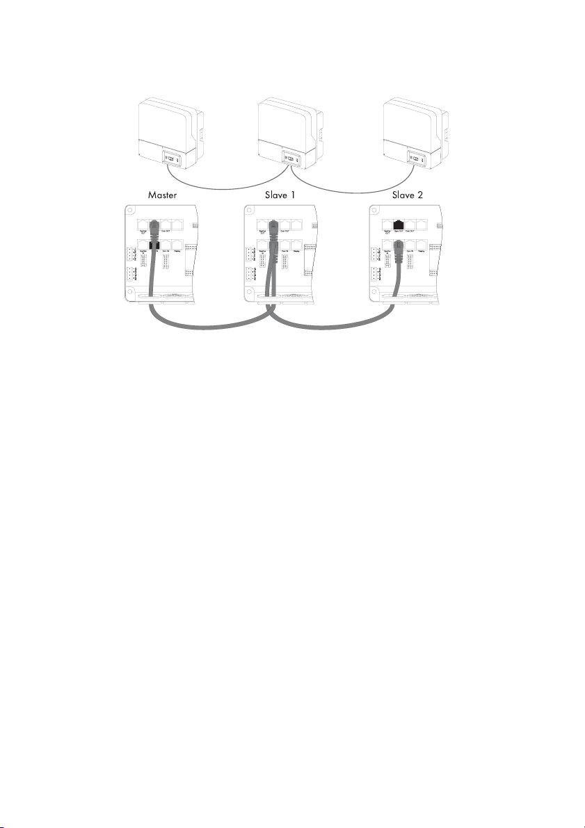
Upon delivery of a Sunny Island, the "SyncIn" socket is terminated.
- Master (first Sunny Island):
- A terminator is plugged into the "SyncIn" socket.
- Insert the communication cable's RJ45 plug in the "SyncOut" socket. The plug snaps
audibly into place.
- Lay the other end of the communication cable in the second Sunny Island.
- Slave 1 (second Sunny Island):
- Remove the terminator from the "SyncIn" socket.
- Plug the RJ45 plug of the communication cable from the master device in the "SyncIn"
socket of the slave 1. The plug snaps audibly into place.
-If no other Sunny Island (slave 2) is to be installed in the island grid system, plug a
terminator in the "SyncOut" socket of the slave 1. The terminator snaps audibly into
place.
-If a third Sunny Island (slave 2) is to be installed in the island grid system, plug the
RJ45 plug of another communication cable in the slave 1's "SyncOut" socket. The plug
snaps audibly into place.
- Lay the other end of the communication cable in the third Sunny Island.
54 SI2012_2224-TEN082311 Technical Description
Page 55
SMA Solar Technology AG Sunny Island Electrical Connection
- Slave 2 (third Sunny Island):
- Remove the terminator from the "SyncIn" socket.
- Plug the RJ45 plug of the communication cable from the slave 1 device in the "SyncIn"
socket of the slave 2. The plug snaps audibly into place.
- Plug a terminator in the "SyncOut" socket of the slave 2. The terminator snaps audibly
into place.
Please Note
The first and last Sunny Islands in a chain must always be terminated.
3. Install all communication leads before you reassemble the rubber element and conduit and
refit them onto the Sunny Island.
4. Fit any unused openings on the enclosure with blind seals.
Information
The "SysCanOut" and "SysCanIn" sockets have no function.
Technical Description SI2012_2224-TEN082311 55
Page 56
Sunny Island Electrical Connection SMA Solar Technology AG
7.5.2 Communication With External Devices
You can connect SMA communication devices (e.g., Sunny Boy Control, Sunny WebBox) or a PC
with the appropriate software to a communication interface. A detailed wiring diagram can be
found in the communication device manual, the software, or on the Internet at www.SMA.de.
This wiring diagram includes:
• Details on the required cable type
• Which of the Sunny Island's connections are used
• Whether or not the communications cables must be terminated
• Whether the PE needs to be connected to the cable shield
You can incorporate an RS485 communication interface into the Sunny Island.
Information
Communication via Powerline/Powerline modem (NLM) is not possible in an island grid
system.
NOTICE!
Electrostatic discharges may damage the communications interface.
• When working on the Sunny Island and when handling the components observe all
ESD safety regulations.
• Eliminate static charge by touching the grounded metal casing.
• Only then should you begin any work.
56 SI2012_2224-TEN082311 Technical Description
Page 57
SMA Solar Technology AG Sunny Island Electrical Connection
When installing the communications interface proceed as follows:
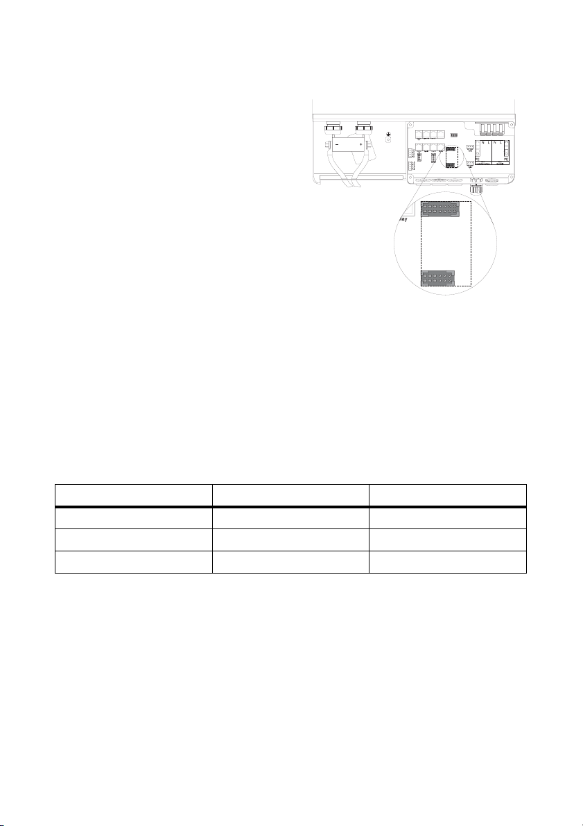
1. Lay the interface's communication cable in
one of the free openings of the cable conduit
seal's inner rubber element.
Plan a sufficient lead length from the
enclosure opening to the "ComOut" socket
on the conductor board in the Sunny Island.
2. Introduce the communication cable into the
enclosure from outside.
3. Insert the RJ45 plug into the "ComOut" socket
in the Sunny Island. The plug snaps audibly
into place.
4. Reassemble the cable conduit unit and
reinsert it into the opening on the floor of the
Sunny Island.
Interface port
(Piggy Back) RS485
5. Fit any unused openings on the enclosure
with blind seals.
6. Connect the other end of the communication
cable to the communication device.
Find the description of which three pins you should use in the installation instructions of the
communication device.
The following table shows the allocation of these pins to the corresponding pins of the RJ45
socket.
WebBox Pin Assignment RS485 RJ45 Socket
2A (Data+)3
7B (Data-)6
5GND2
7. Terminating the Sunny Island using RS485.
The RS485 data bus of Sunny Island is terminated with a plug. This plug is already preinstalled in your Sunny Island. Remove this plug only if you intend to connect another
communication device.
8. Plug the communications interface into the board.
Technical Description SI2012_2224-TEN082311 57
Page 58
Sunny Island Electrical Connection SMA Solar Technology AG
The Sunny Island can be operated at different transmission rates (1200 to 19200 bps), to
communicate with external devices. The parameter "250.06 ComBaud" must be set
correspondingly.
Setting the Baudrate
If Sunny Boys are connected to the communications bus, then the baud rate must be set
to 1200 bps (factory setting).
The Sunny Island uses the SMA-Net protocol for communication.
58 SI2012_2224-TEN082311 Technical Description
Page 59
SMA Solar Technology AG Sunny Island Electrical Connection
7.6 Additional Connections
7.6.1 Battery Temperature Sensor
The battery temperature sensor measures the temperature of the connected battery. This is necessary
since the optimum charging voltage for a battery largely depends on the temperature. Further
information is provided in section 12.4 "Charge Control" (Page 122). A battery temperature sensor
is provided with the Sunny Island (see the delivery scope description).
Defective Battery Temperature Sensor
If the battery temperature sensor is rendered inoperative, e.g., due to a short circuit or
broken cable, the Sunny Island works with a fixed setting which, however, leads to an
insufficient charge of the battery in the long run. In this case the Sunny Island's display
shows a warning.
• Replace the defective battery temperature sensor promptly.
• Always operate the Sunny Island with the battery temperature sensor (included in
the delivery).
NOTICE!
Damage to the battery due to faulty installation
• Always install the battery temperature sensor included in the delivery.
• Do not drill holes into the battery when installing the battery temperature sensor.
- Fasten the battery temperature sensor to the outside of one of the battery cells.
- Choose a position in the space between two cells or in the middle area of the
battery bank, where the heat generation during operation is greatest.
One battery temperature sensor per cluster!
A battery temperature sensor is provided with each Sunny Island.
Only one battery temperature sensor, which is connected to the corresponding master, is
required for a cluster.
Technical Description SI2012_2224-TEN082311 59
Page 60
Sunny Island Electrical Connection SMA Solar Technology AG
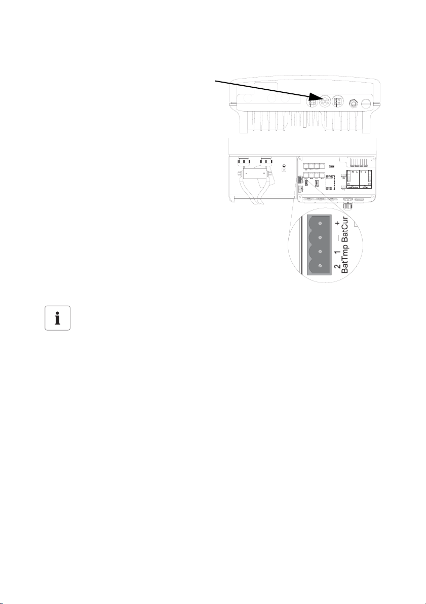
When connecting the battery temperature sensor proceed as follows:
1. Pierce the rubber plugs with a pointed tool.
2. Fit the cables with wire sleeves.
3. Introduce both cables from the outside
through the opening.
4. Plug one wire into each of the "BatTmp"
contacts of the 4-pole terminal included.
5. Tighten the screws of the contact.
6. If needed, install a battery current sensor
before you insert the plug into the "BatCur
BatTmp" socket on the board.
Installation notice
The polarity of the two conductors has no influence on the function of the battery
temperature sensor.
60 SI2012_2224-TEN082311 Technical Description
Page 61
SMA Solar Technology AG Sunny Island Electrical Connection
7.6.2 Battery Current Sensor
In addition to the internal measurement, the Sunny Island provides the possibility to measure the
battery current via a shunt. You need this function if you intend to operate additional DC generators
and DC loads in your island grid system.
NOTICE!
Damage to the battery due to the connection of additional DC generators or DC
loads to the island grid system.
In this operating situation, the Sunny Island's internal current measurement works
imprecisely; the charge state of the battery is not determined exactly.
• Install an external battery current sensor (shunt).
Battery Current Sensor
Install a battery current sensor if there are charge or discharge DC currents of over
200 A.
Connect the battery current sensor to the master.
Use cables of intrinsically safe circuits.
Always use cables of intrinsically safe circuits for the connection of battery current
sensors. "Intrinsically safe" means here that the cable is double-insulated and that the wire
melts but the insulation remains intact in the event of a short circuit. In addition, the cable
is not combustible. In order to avoid measuring errors, make sure to use twisted cables
(see DIN VDE 0100-430).
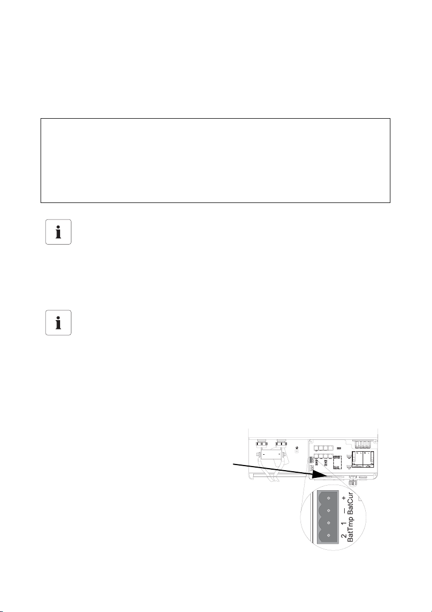
When connecting the battery current sensor proceed as follows:
1. Pierce the rubber plugs with a pointed tool.
2. Fit the cables with wire sleeves.
3. Introduce both cables from the outside through
the opening.
Technical Description SI2012_2224-TEN082311 61
Page 62
Sunny Island Electrical Connection SMA Solar Technology AG
Installation notice
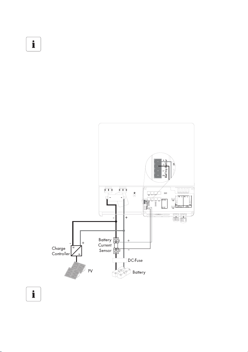
The battery current sensor must be looped around the negative pole of the battery. In
addition, the contact of that battery current sensor which is connected to the Sunny Island
(1) must be connected to the terminal "BatCur+" (see following diagram).
If the battery current sensor is connected as described above,
• positive battery current means that the battery is discharging (current from the
battery)
• negative battery current means that the battery is charging (current into the battery)
Information
Charge controller and PV in the illustration above are only examples.
62 SI2012_2224-TEN082311 Technical Description
Page 63
SMA Solar Technology AG Sunny Island Electrical Connection
4. Plug one wire into each of the "BatCur" contacts of the 4-pole terminal included.
5. Tighten the screws of the contact.
Observe the correct polarity of the leads (see also the installation notice above).
6. Insert the plug into the "BatCur BatTmp" socket on the board.
Commissioning the Battery Temperature Sensor
When connecting the battery temperature sensor, set up the internal offset on the Sunny
Island during the first commissioning of the island grid system (see chapter 9.3
"Commissioning the Battery Current Sensor" (Page 81)).
7.6.3 Multi-function Relays 1 and 2
DANGER!
Death hazard due to faulty insulation
Separate the relay cable safely away from the communication area.
• Strip the wires of the relay cable.
• Fit each individual wire with the silicon tube included in the delivery.
• The device should not be operated without the silicon tube.
The Sunny Island offers you several options for the control of internal and external processes. To this
end, the device is equipped with two multi-function relays to which you can assign functions with the
parameters "241.01 Rly1Op" and "241.02 Rly2Op" (see chapter 14 "Relay" (Page 152)).
Information
The slave devices' relays can also be used and programmed separately.
Information on the switching capacity of the relays is provided in section 20 "Technical
Data" (Page 197).
Technical Description SI2012_2224-TEN082311 63
Page 64
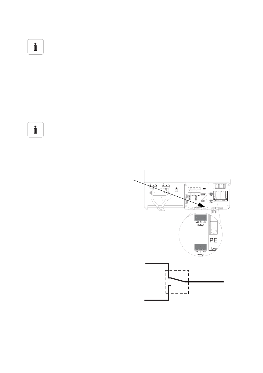
Sunny Island Electrical Connection SMA Solar Technology AG
Operating principles of the relays
The relays are changeover contacts; they can be used as normally closed contacts
(NCC) or as normally open contacts (NOC).
The relay functions are listed as NO contact functions, in other words, the contact is
closed if the relay is activated by selecting the function. An exception is "Alm" (alarm), in
which case the relay has a break function. This means that the relay is normally activated,
opening the contact. Only in case of a failure is it deactivated and closes the contact
(activating, for example, a warning light).
Please note:
You can only assign one function to the relay.
Proceed as follows when installing the relay connections:
1. Pierce the rubber plugs with a pointed tool.
2. Fit the cables with wire sleeves.
3. Introduce both cables from the outside
through the opening.
4. Insert the wires in the "Relay1" or "Relay2"
sockets of the 3-pole terminal clamps
provided.
5. Tighten the screws on the sockets.
6. Pay attention to the designation of the pins:
- NC: Normally closed (closed when
idle)
NC
C
- C: Contact (operation contact)
- NO: Normally opened (opened in
NO
standby)
7. Insert the plug into the appropriate socket
on the board.
64 SI2012_2224-TEN082311 Technical Description
Page 65
SMA Solar Technology AG Sunny Island Electrical Connection
Load shedding
The Sunny Island can automatically switch off loads to protect the batteries from deep discharge.
To do this, an external (AC or DC) power contactor must be installed between the Sunny Island and
the loads (see also chapter 19.3 "Accessories (Optional)" (Page 195)).
NOTICE!
If a relay is used for load shedding, the loads connected to the power contactor will no
longer be supplied with electricity in the event of a fault in the island grid system, even
when the grid is available.
Generator Start
The Sunny Island can control generators. It supports generators that can be started and stopped by
a single contact and generators that require more than one contact (in combination with the
optionally available generator manager (GenMan)).
Default Setting of the Relays
By default, relay 1 is set to the start generator function "AutoGn" and relay 2 is set to the
load shed function "AutoLodSoc".
The first figure in section 2 "System Overview" (Page 12) shows the principal connection.
Technical Description SI2012_2224-TEN082311 65
Page 66
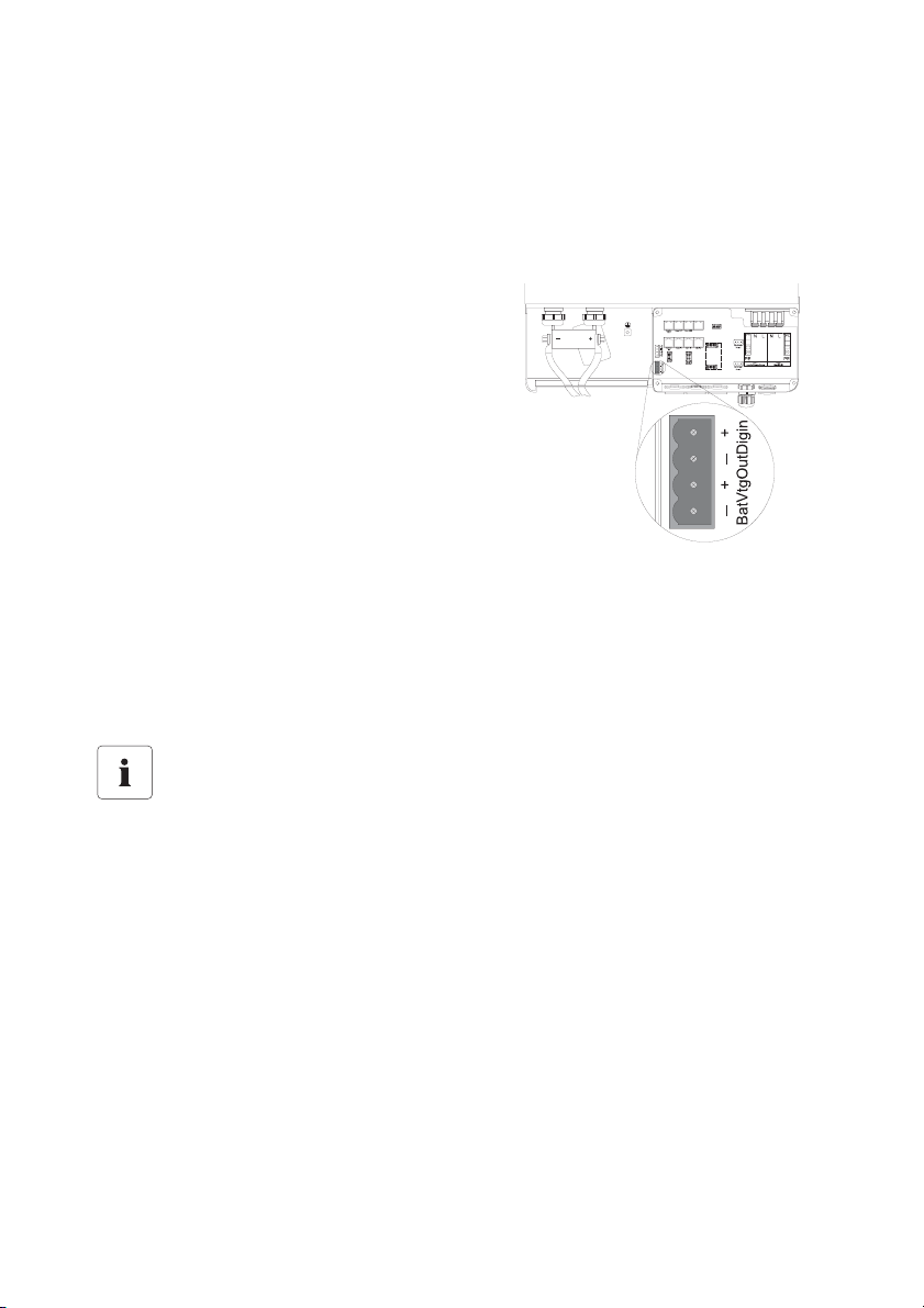
Sunny Island Electrical Connection SMA Solar Technology AG
7.6.4 BatVtgOut Power Supply
The battery voltage is conducted to the outside at these terminals. It is fused at both poles by PTC
thermistors (max. 0.75 A) and can fluctuate depending on the battery status. This connection can,
for example, be used to supply a DC contactor for load shedding.
Proceed as follows when connecting the power supply:
1. Pierce the rubber plugs with a pointed tool.
2. Fit the cables with wire sleeves.
3. Introduce both cables from the outside
through the opening.
4. Plug one wire into each of the "BatVtgOut"
contacts of the 4-pole terminal included.
5. Tighten the screws of the contact.
6. If needed, install DigIn before you insert
the plug into the "DigIn BatVtgOut" socket
on the board.
7.6.5 DigIn Digital Input
These terminals function as a digital input for external electric sources. For example, the feedback
contact for the GenMan (GenRn) is connected here.
Information
If you connect a GenMan, or operate the system with the generator and utility (GenGD)
in parallel, use the relays on the master device in order to activate the respective
functions.
66 SI2012_2224-TEN082311 Technical Description
Page 67
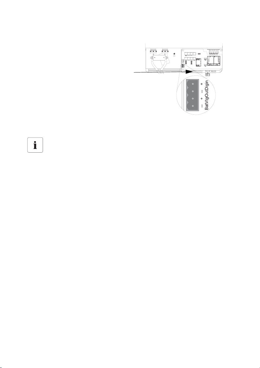
SMA Solar Technology AG Sunny Island Electrical Connection
Proceed as follows when connecting the digital input:
1. Pierce the rubber plugs with a pointed tool.
2. Fit the cables with wire sleeves.
3. Introduce both cables from the outside
through the opening.
4. Plug one wire into each of the "DigIn"
contacts of the 4-pole terminal included.
5. Tighten the screws of the contact.
6. Insert the plug into the "DigIn BatVtgOut"
socket on the board.
Further Information
For further information on connecting and operating the GenMan see the respective
product documentation.
Technical Description SI2012_2224-TEN082311 67
Page 68
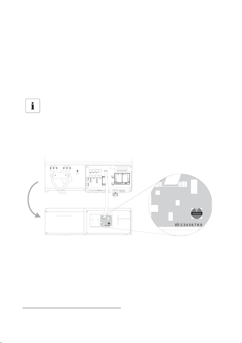
Sunny Island Electrical Connection SMA Solar Technology AG
7.7 Configuring a System with Several Sunny Islands
1)
The Sunny Island can be configured for various system combinations:
• Single-phase system with one Sunny Island
• Single-phase system witn two or three Sunny Islands connected in parallel
• 3-phase system with three Sunny Islands (one Sunny Island per phase)
Carry out the configuration before the first commissioning of the system. Each Sunny Island must be
configured with the aid of the rotary code switch. Upon delivery this rotary code switch is set to "0".
Please note:
The position of the rotary code switch must only be changed if you intend to operate more
than one Sunny Island in your system!
The rotary code switch is found on the back of the back of the display, on the inside of the lower
enclosure cover of the Sunny Island.
To configure the system proceed as follows:
With a screwdriver (2.5 mm), turn the mark on the rotary code switch to the desired position.
Set the rotary code switch to
-0 for master
- 1 for slave 1
- 2 for slave 2
1)
These applications are only possible with firmware versions 3.0 and above.
68 SI2012_2224-TEN082311 Technical Description
Page 69
SMA Solar Technology AG Sunny Island Electrical Connection
The configuration possibilities of the rotary code switch at a glance:
Parameter Meaning
0Master
1Slave 1
2Slave 2
7.8 Concluding Tasks
1. Remove all tools from the enclosure.
2. Have all cables been laid so as to be strain-relieved?
3. Are there no communication cables inside the Sunny Island which are touching a stripped
230 V wire?
4. Are all cable conduits on the Sunny Island sealed?
5. Have all unused openings been closed with blind seals?
6. Close the lower enclosure cover (see chapter 6.2 "Closing the Sunny Island" (Page 38)).
The installation of the Sunny Island and Sunny Remote Control 1 is complete.
Technical Description SI2012_2224-TEN082311 69
Page 70
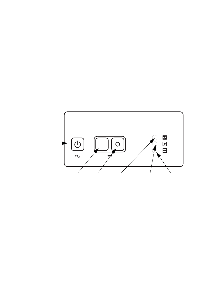
Control Elements SMA Solar Technology AG
8 Control Elements
Before commissioning the island grid system, familiarize yourself with the operation of the device.
The Sunny Island is operated with the control panel on the enclosure only under the standard setup
(for default values see chapter 17.2 "Adjustable System Parameters" (Page 166)).
To change the Sunny Island's parameter setup you need the Sunny Remote Control 1 (SRC-1)
external display.
8.1 Sunny Island
8.1.1 Control Panel on the Enclosure
The following diagram describes the elements of the control panel:
Start / Stop button
DC start
button
DC stop
button
Inverter LED
Grid LED
Battery LED
8.1.2 Control Panel Buttons
The Sunny Island's control panel has three buttons.
• Start / Stop starts and stops the inverter operation of the Sunny Island (see also chapter 10.1
"Switching On and Off" (Page 83)).
• DC start turns ont the Sunny Island (standby).
• DC stop turns off the Sunny Island
8.1.3 Meaning of the Light-Emitting Diodes (LEDs)
The three LEDs show, from top to bottom, state messages for
• Sunny Island (inverter LED)
• Grid / Generator (grid LED)
• Battery (battery LED)
70 SI2012_2224-TEN082311 Technical Description
Page 71
SMA Solar Technology AG Control Elements
Depending on the message, the corresponding LED glows red, green, orange, or not at all.
The following table describes the meanings of the color signals from the inverter LED:
Green Red Orange
Operating mode of the
Sunny Island
— — — Off (device has been switched off)
— — ON Standby (no inverter operation)
ON — — In operation
— ON — Failure or error
The following table describes the meanings of the color signals from the grid LED:
Green Red Orange
Operating mode
grid/generator
— — — if applicable, no grid/generator
(conduction possible)
— — ON Synchronization to the external grid /
generator
ON — — Operation with grid / generator
— ON — Failure or error
The following table describes the meanings of the color signals from the battery LED:
Green Red Orange Battery charge level
— — — Off (device has been switched off)
ON — — 100 % — 50 %
— — ON 50 % — 20 %
— ON — 20 % — 0 %
Technical Description SI2012_2224-TEN082311 71
Page 72
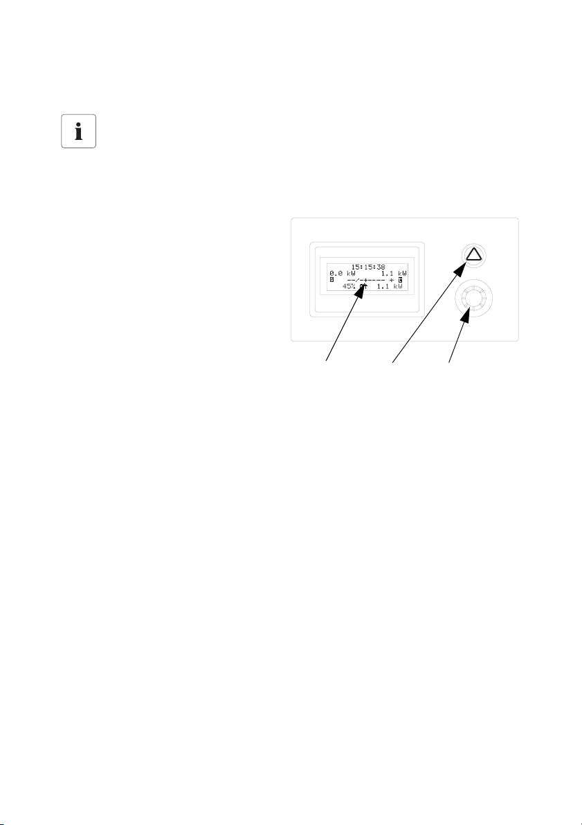
Control Elements SMA Solar Technology AG
8.2 Sunny Remote Control 1
Information
The Sunny Island is controlled via the external display (Sunny Remote Control 1).
You can navigate the Sunny Island's menus with the external display (Sunny Remote Control 1).
The Sunny Remote Control 1 consists of
•Display
•Key
• rotating pushbutton
Display
Key
rotating push
button
72 SI2012_2224-TEN082311 Technical Description
Page 73
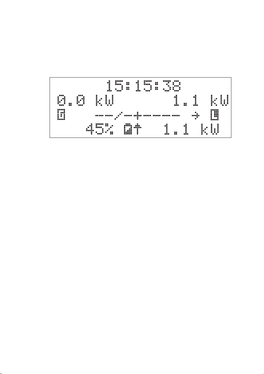
SMA Solar Technology AG Control Elements
8.2.1 Display Messages
The Sunny Remote Control 1 display consists of four lines with 20 characters each. You can find
details on the symbols shown in chapter 10.2.1 "Standard View 1" (Page 92).
1
2
3
4
1Row: Uhrzeit in [hh:mm:ss]
2Row: grid or generator power in kW ("TotExtPwrAt")
ggf. Pfeil in Energieflussrichtung (z. B. Š = Einspeiseleistung PV-Generator)
Load power in kW ("TotExtPwrAt" + "TotInvPwrAt")
3Row: Symbols for grid / generator
Loads
Generator relay or load shedding relay: On = - Off = /
ggf. Pfeil in Energieflussrichtung (z. B. ‡)
4Row: state of charge of battery (SOC)
Symbol for battery
Pfeil in Energieflussrichtung ( ‰ = Entladen, Š = Laden)
Inverter power in kW ("TotInvPwrAt")
- positive value: the battery is discharging/the Sunny Island is feeding the
loads
- negative value: the battery is charging
8.2.2 Key
If there is an error during operation, the back of the pushbutton glows red.
If you push the key, you acknowledge the error and the warning light goes off again (see also
chapter 18.1 "Error Confirmation" (Page 184)).
Technical Description SI2012_2224-TEN082311 73
Page 74

Control Elements SMA Solar Technology AG
8.2.3 Rotating Pushbutton
The Sunny Remote Control 1 is controlled via a rotating pushbutton. This pushbutton allows simple
navigation of the Sunny Island menus (see chapter 10.2 "Navigation Area" (Page 89)).
The rotating pushbutton can be pushed or turned.
•Turn:
- Moves up and down the menu
- Entering values
•Push:
- Open/close menu
- Select/cancel function
- Select value
- Confirm entry
- Answers yes/no
- Starts the device (hold down the button while on standby)
- Stops the device (hold down the button during operation)
Operation of the Sunny Island with the Sunny Remote Control 1 using the rotating pushbutton is
described in detail in chapter 10 "Operating the Sunny Island" (Page 83).
In the remainder of the manual, the "rotating pushbutton" will only be referred to as "button".
8.2.4 MMC/SD card
The Sunny Remote Control 1 provides an MMC/SD card for firmware updates and as a service
interface. For details, refer to section 10.4 "Saving Data onto a MMC/SD Card" (Page 107).
74 SI2012_2224-TEN082311 Technical Description
Page 75
SMA Solar Technology AG (First) Commissioning
9 (First) Commissioning
9.1 Requirements
Check the connections
Before starting the commissioning process, ensure that all electrical connections have the
correct polarity and make sure that everything is connected according to the instructions
in chapters 7 "Sunny Island Electrical Connection" (Page 39).
Always save data
Always use the MMC/SD card for saving data and events. This way, in case of a failure,
the SMA Solar Technology AG can help you quickly.
The Quick Configuration Guide (QCG) allows you to quickly install and commission your island
grid system.
• On the Sunny Island, choose one of the following positions:
- Start system
- New system
- New battery
• Set up the parameters of the desired system specifically.
QCG with Sunny Remote Control 1 only
You can read and set up lists of menus, parameters and errors only with the Sunny
Remote Control 1!
You can start up the Sunny Island without an external display as well. In this case the
Sunny Island works only with the default parameters
(see chapter 8 "Control Elements" (Page 70)).
Technical Description SI2012_2224-TEN082311 75
Page 76
(First) Commissioning SMA Solar Technology AG
9.2 Starting the Quick Configuration Guide (QCG)
Information
The QCG sets up all parameters values automatically. Reasonable operation is possible
this way, with little manipulation.
The QCG is automatically activated when the device is started for the first time. Please continue
reading under point 7, otherwise follow this list.
1. Insert the NH fuse in the BatFuse or close the
BatFuse's DC disconnector.
2. Start the Sunny Island.
Press the DC start key on the Sunny Island
3. The Sunny Island initiates the startup phase. Wait
for the following displays to finish.
HSI2012BFSBOOT V1.002
SI2224
@SMA 2007
4. "To init system hold <Enter>" is displayed after
the startup phase.
To init system
hold <Enter>
5. Press and hold the pushbutton on the Sunny
Control 1.
During this procedure a bar appears on the
display.
76 SI2012_2224-TEN082311 Technical Description
Page 77
SMA Solar Technology AG (First) Commissioning
6. When the bar on the display disappears and the
Sunny Remote control emits a tone signal:
Let go of the Sunny Remote Control pushbutton.
7. You are now in the Quick Configuration Guide
(QCG).
By turning the pushbutton you can now choose
between the following options:
001#01 ¿
Start Menu
Start System
- "Start System" (if you have accidentally
accessed the QCG and would only like to
restart the system)
- "New Battery" (if you would like to change
the main battery settings, but retain the system
configuration)
001#01 ¿
Start Menu
New Battery
- "New System" (if you would like to start a
new system or perform changes to the system
configuration)
001#01 ¿
Start Menu
New System
"New Battery"
When you want to install a new battery in the island grid system, you need the "New
Battery" option.
Only specific battery settings are reset and set to new values. The overall system settings
are not affected.
Technical Description SI2012_2224-TEN082311 77
Page 78

(First) Commissioning SMA Solar Technology AG
The following parameters must be set when "New Battery" is selected:
(default setting shown in bold)
- Battery type: 002#05 BatTyp (VRLA, FLA, NiCd)
- Battery voltage: 002#06 BatVtgLst (22 V, 24 V in 2 V increments for FLA and VRLA, 21.6
V, 22.8 V, 24 V in 1.2 V increments for NiCd), 24 V Sunny Island 2224, 12 V Sunny
Island 2012
- Nominal battery capacity: 002#07 BatCpyNom (100 Ah to 10000 Ah, preset 140 Ah
for Sunny Island 2224, )
The following parameters must be set when "New System" is selected:
(default setting shown in bold)
- System configuration: 003#01 (selection see "Overview of System Configurations:"
(Page 79)), presetting is "1phase 1SI"
a)
- Voltage / Frequency type: 003#02 AcVtgFrqSet (230V_50Hz, 220V_60Hz)
- Date: 003#03 Dt (dd.mm.yyyy)
- Time: 003#04 Tm (hh:mm:ss)
- Battery type: 003#05 BatTyp (VRLA, FLA, NiCd)
- Battery voltage: 003#06 BatVtgLst (22 V, 24 V in 2 V increments for FLA and VRLA, 21.6
V, 22.8 V, 24 V in 1.2 V increments for NiCd), 24 V Sunny Island 2224, 12 V Sunny
Island 2012
- Nominal battery capacity: 003#07 BatCpyNom (50 Ah bis 10000 Ah, 140 Ah)
- External power supply unit: 003#08 ExtSrc (PvOnly, Gen, Grid, GenGrid)
- Maximal grid current: 003#09 GdCurNom (0 to 25 A, 16 A)
- Maximal generator current: 003#10 GnCurNom (0 to 25 A, 16 A)
- Generator interface: 003#11 GnStrMod (Manual, GenMan, Autostart)
a)
These applications are only possible with firmware versions 3.0 and above.
78 SI2012_2224-TEN082311 Technical Description
Page 79
SMA Solar Technology AG (First) Commissioning
Overview of System Configurations:
2)
The system configuration is described extensively in chapter 7.7 "Configuring a System with Several
Sunny Islands" (Page 68).
Displayed Text Meaning
1phase 1SI single-phase system, 1 Sunny Island
1phase 2SI single-phase system, 2 Sunny Islands
1phase 3SI single-phase system, 3 Sunny Islands
Three 3SI 3-phase system, 3 Sunny Islands
8. After entering the parameters, the following
message appears on the display:
"Init Device OK
Init Device OK
START?
START?"
9. Confirm the question:
Press and hold the pushbutton on the Sunny
Remote Control 1.
10. The following message appears:
„ST(A)NDBY: To Start INV(erter) hold <Enter>“
The QCG is complete.
STNDBY: To Start
INV hold <Enter>
To start the Sunny Island:
11. Press and hold the pushbutton on the Sunny
Remote Control 1.
During this procedure a bar appears on the
display.
12. When the bar on the display disappears and the
Sunny Remote control emits a tone signal:
Let go of the Sunny Remote Control pushbutton.
13. The Sunny Island starts.
The Sunny Island is in operation.
2)
These applications are only possible with firmware versions 3.0 and above.
Technical Description SI2012_2224-TEN082311 79
Page 80
(First) Commissioning SMA Solar Technology AG
If there is an error message
If the device displays an error message, this error must be fixed before the device can be
put into operation. Use the information in section 18 "Troubleshooting/Problem Solving"
(Page 184).
Parameter Lists
Further details concerning the modifiable parameters are found in chapter 17 "Parameter
List Overview" (Page 160).
Note that you must first enter the installer password before some parameters can be
changed (see section 10.3.2 "Setting the Installer Password" (Page 102)). In addition,
some parameters can only be changed in standby mode (see section 10.1.2 "Stopping"
(Page 85)).
80 SI2012_2224-TEN082311 Technical Description
Page 81
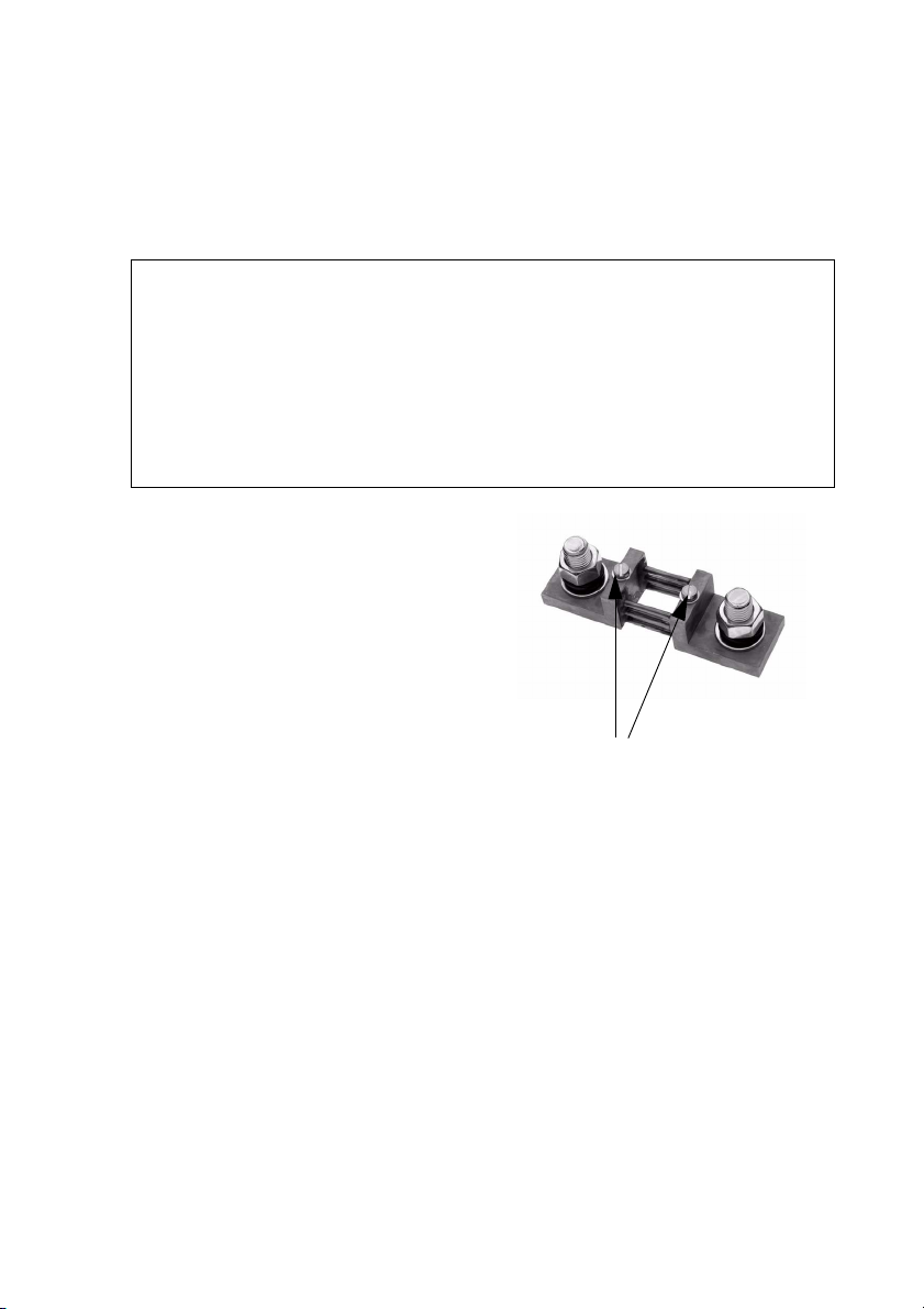
SMA Solar Technology AG (First) Commissioning
9.3 Commissioning the Battery Current Sensor
When connecting a battery current sensor to the Sunny Island the internal offset must be calibrated.
Proceed as follows:
1. Place the Sunny Island in standby mode (see section 10.1.2 "Stopping" (Page 85)).
2.
3. Remove the "BatCur+" wire from the terminall
clamp 1 of the battery current sensor.
4. Connect both the "BatCur+" and the "BatCur-"
wires to the terminal clamp 2.
5. Start the Sunny Island
6. Set the following parameters:
Choose the type of battery current sensor:
- "225.01 BatCurSnsTyp" (None / 50 mV /
Set the maximal current for the battery current
sensor (e.g., 400 A / 60 mV):
- "225.02 BatCurGain60": (for a 60 mV
- "225.03 BatCurGain50": (for a 50 mV
7. Start the self-calibration:
- "225.04 BatCurAutoCal" to "Start"
The Sunny Island conducts a self-calibration.
NOTICE!
System error due to wrong parameter entry
All parameter settings which could affect the operating safety of the island grid
system are protected/locked by the installer password.
• Only qualified personnel should change and set system parameters.
• Enter the installer password (see chapter 10.3.2 "Setting the Installer
Password" (Page 102)).
60 mV). Only after activation of the
parameter with 50 mV or 60 mV will other
Terminal clamps battery current sensor
parameters (02, 03 and 04 in the menu
"225 Battery Current Sensor") be shown
and activated.
output (EU-Standard))
output (US-Standard))
Technical Description SI2012_2224-TEN082311 81
Page 82
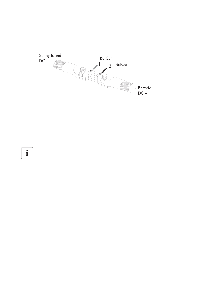
(First) Commissioning SMA Solar Technology AG
8. Subsequently, check the offset error
"120.06 TotBatCur" should be (close to) zero
9. Switch off the Sunny Island and remove all voltages (see chapter 10.1 "Switching On and
Off" (Page 83)).
10. Connect the "BatCur+" wire to the battery current sensor's terminal clamp 2 again.
Make sure the wires have the correct polarity.
- BatCur+ to terminal clamp 1
- BatCur- to terminal clamp 2
11. Start the Sunny Island (see chapter 10.1.1 "Switching On/Starting" (Page 83)).
12. Check the current direction: "120.06 TotBatCur"
Current direction
Battery discharge:
• no generator/grid connected
• Loads are being supplied
The value of the battery current is positive
Charging the battery
• Generator/grid connected
• Loads not being/being marginally supplied
• Battery is being charged
The value of the battery current is positive
82 SI2012_2224-TEN082311 Technical Description
Page 83
SMA Solar Technology AG Operating the Sunny Island
10 Operating the Sunny Island
10.1 Switching On and Off
10.1.1 Switching On/Starting
WARNING!
Danger due to incorrect wiring of the island grid system
Only qualified electricians should carry out the first commissioning. Check the island grid
system beforehand for
• correct electric cabling and connections
• voltages and polarities
Start the island grid system with the Sunny Island
Information
The island grid system can also be operated without an external display (Sunny Remote
Control 1). In this case the Sunny Island works only with the default parameters (see
chapter 17.2 "Adjustable System Parameters" (Page 166)).
Proceed as follows:
1. Insert the NH fuse in the BatFuse or close the BatFuse's DC disconnector.
2. Press the DC start key on the Sunny Island
Wait approx. 20 to 30 seconds.
The Sunny Island is switched on
3. Press and hold the start / stop button on the Sunny Island.
During the start procedure the inverter LED goes from orange to green.
4. Let go of the start / stop button
The inverter LED glows green continually.
The Sunny Island is in operation.
Technical Description SI2012_2224-TEN082311 83
Page 84

Operating the Sunny Island SMA Solar Technology AG
Start the island grid system with the Sunny Remote Control 1
1. Insert the NH fuse in the BatFuse or close the
BatFuse's DC disconnector.
2. Press the DC start key on the Sunny Island
The Sunny Island is switched on
3. The Sunny Island initiates the startup phase.
Wait for the following displays to finish.
HSI2012BFSBOOT V1.002
SI2224
@SMA 2007
4. "To init system hold <Enter>" is displayed after the
startup phase.
To init system
hold <Enter>
5. If you want to go into the QCG, press and hold
the Sunny Remote Control 1's pushbutton.
Instructions on how to proceed further can be
found in chapter 9.2 "Starting the Quick
Configuration Guide (QCG)" (Page 76).
6. If you do not press the pushbutton within 5
seconds, the Sunny Island skips the QCG.
The following message appears:
STNDBY: To Start
INV hold <Enter>
„ST(A)NDBY: To Start INV(erter) hold <Enter>“
84 SI2012_2224-TEN082311 Technical Description
Page 85
SMA Solar Technology AG Operating the Sunny Island
7. Press and hold the pushbutton on the Sunny Remote Control 1.
8. The Sunny Remote Control 1 emits a tone.
9. The Sunny Island starts.
10. Let go of the pushbutton.
The Sunny Island is in operation.
Starting the Sunny Island automatically
Even if the "250.01 AutoStr" parameter is set, the Sunny Island must be manually started
for inverter operation after each DC start once, each time the DC circuit breaker is started.
If there is an error message
If the device displays an error message, this error must be fixed before the device can be
put into operation. Use the information in section 18 "Troubleshooting/Problem Solving"
(Page 184).
10.1.2 Stopping
Stopping the system with the Sunny Island
Set the Sunny Island to standby.
Proceed as follows:
1. Press and hold the start / stop button on the Sunny Island until the inverter LED glows orange
continuously.
During the stop procedure the LED goes from green to orange.
2. Let go of the start / stop button
The Sunny Island has stopped.
The device is now in standby mode.
Technical Description SI2012_2224-TEN082311 85
Page 86
Operating the Sunny Island SMA Solar Technology AG
Stopping the system with Sunny Remote Control 1
Set the Sunny Island to standby using the external display.
Proceed as follows:
1. Press and hold the pushbutton on the Sunny
Remote Control 1.
The following display appears:
2. Hold the pushbutton as long as the remaining
time for the stop process is shown on the display
as bars.
3. The display changes
4. Let go of the pushbutton.
5. The Sunny Island has stopped.
DANGER!
Death hazard due to high voltages
The island grid system is in "standby" operating modus!
• Do not open the device!
• Do not work on the island grid system!
There are still voltages present on the Sunny Island (DC and AC sides).
• Switch off the Sunny Island
• Disconnecting the Sunny Island from Voltage Sources
Hold to stop...
¿¿¿¿¿¿¿¿¿¿¿¿¿¿¿¿
STNDBY: To Start
INV hold <Enter>
Consumption in standby mode
In standby mode the Sunny Island still requires about 6 W of power from the batteries.
86 SI2012_2224-TEN082311 Technical Description
Page 87
SMA Solar Technology AG Operating the Sunny Island
10.1.3 Switching Off
Switch off the Sunny Island in the following way:
1. Disconnect all loads.
2. Place the in standby mode (see section 10.1.2 "Stopping" (Page 85)).
3. Press the DC stop key on the Sunny Island
The Sunny Island is switched off
DANGER!
Death hazard due to high voltages
The island grid system is disconnected! There are still voltages present on the Sunny
Island (DC and AC sides).
• Disconnecting the Sunny Island from Voltage Sources
Information
You can only ensure that all internal meter readings/values are saved by using this
switching sequence.
Ensure that the device cannot be reconnected!
Wait 30 seconds before switching the device on again. Otherwise the smooth operation
of the Sunny Island cannot be guaranteed.
10.1.4 Disconnecting the Device from Voltage Sources
1. Switch off the Sunny Island (see chapter 10.1.3 "Switching Off" (Page 87)).
2. Remove the NH fuse from the BatFuse and/or open the BatFuse's DC disconnector.
The Sunny Island is disconnected from the battery
3. Separate the Sunny Island from all AC voltage sources.
4. Make sure that the Sunny Island has been disconnected securely from all voltage sources.
5. Wait at least 15 minutes.
The capacitors discharge and allow the voltage inside the device drops to a safe level.
6. The Sunny Island is now completely free of voltage.
7. You can now open the lower enclosure cover of the Sunny Island.
Technical Description SI2012_2224-TEN082311 87
Page 88
Operating the Sunny Island SMA Solar Technology AG
10.1.5 Restarting the System after Automatic Shutdown
NOTICE!
System shutdown due to, for example, wrong device settings
• Before and after recommissioning, inspect the whole island grid system for errors
- Wrong wiring?
- Have any components failed?
- Are there any wrong parameter settings on the Sunny Island?
• If applicable, clear the errors.
If the Sunny Island has swiched itself off due to batteries which are too deeply discharged, proceed
as follows to restart:
1. Press the DC stop key on the Sunny Island
Wait!
Wait a minute before you restart the Sunny Island with the DC start key. The capacitors
must discharge first.
2. After waiting for a minute, switch on the Sunny Island.
Press the DC start key on the Sunny Island
Information
If, as in rare cases, it is not possible to restart after one minute, wait a little longer. Try
again. A possible cause can be component tolerances.
3. Start the Sunny Island (see chapter 10.1.1 "Switching On/Starting" (Page 83)).
Charging the battery
Once the system is switched on again, it is important that the batteries are charged. If the
grid is available again, and/or the generator starts, the grid/generator will recharge the
batteries after a few minutes.
4. Monitor the Sunny Island connection in the charging process with the
Sunny Remote Control 1.
5. Check that all other energy generators in the island grid system are working correctly.
88 SI2012_2224-TEN082311 Technical Description
Page 89
SMA Solar Technology AG Operating the Sunny Island
If Sunny Island begins to operate in battery-preservation mode, disconnect the
loads!
If the Sunny Island enters the battery-preservation mode immediately after restarting see
chapter 12.5 "Battery Preservation Mode" (Page 127).
• Verify the availability of the grid.
• Reconnect the loads again only after the Sunny Island is operating in charge mode.
10.2 Navigation Area
The navigation area comprises the home screen as well as the main menu items
• 100# Meters (display values)
• 200# Settings
• 300# Diagnosis
• 400# Failure/Event (lists)
• 500# Operation (functions during operation)
• 600# Direct Access
A main menu is subdivided into submenus.
From a submenu you can select another submenu or a parameter.
NOTICE!
Damage to the system due to wrong parameter entry
• Only qualified personnel should change and set system parameters.
You can access the navigation area from two access levels:
•User level
• Installer level (only with password)
The menu items and parameters which allow the editing of system parameters are accessible after
entering the installer password (see chapter 10.3.2 "Setting the Installer Password" (Page 102)).
Technical Description SI2012_2224-TEN082311 89
Page 90
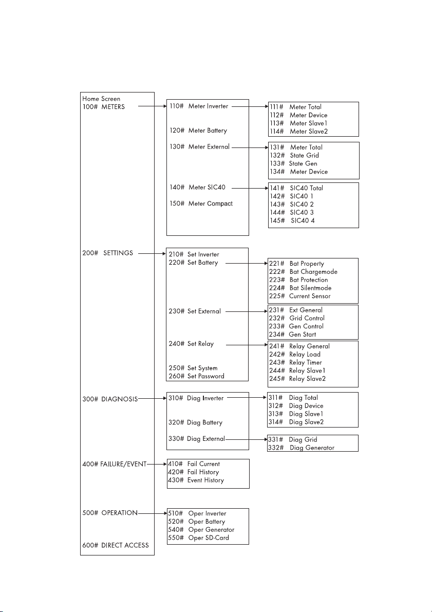
Operating the Sunny Island SMA Solar Technology AG
Overview of the menu area:
Main menu Submenu 1
Submenu 2
90 SI2012_2224-TEN082311 Technical Description
Page 91

SMA Solar Technology AG Operating the Sunny Island
100# Meters (display values): In this main menu you can find the displayed values of the
following components of the island grid system:
• 110# Meter Inverter - Sunny Island
• 120# Meter Battery
• 130# Meter External - grid/generator
• 140# Meter SIC40 - battery charge regulator
• 150# Meter Compact - compact display of the commissioning values
By opening the corresponding submenus or the second tier of submenus, you can see the
parameters (for example, Parameter "112.03 InvVtg").
200# Settings: In the following submenus you can see and edit the system parameters:
• 210# Set Inverter
• 220# Set Battery
• 230# Set External - grid/generator
• 240# Set Relay
• 250# Set System
• 260# Set Password
300# Diagnosis: In the following submenus you can see the system data:
• 310# Diag Inverter - device data (Sunny Island)
• 320# Diag Battery - battery data
• 330# Diag External - grid/generator
400# History: In the following submenus you can see various error and event lists:
• 410# Fail Current - present errors
• 420# Fail History - warnings and errors to date
• 430# Event History
500# Operation - functions during operation: In the following submenus you can see and
edit the operating parameters:
• 510# Oper Inverter
• 520# Oper Battery
• 540# Oper Generator
• 550# Oper SD Card - MMC/SD card
600# Direct Access: In this main menu you can access settings and display values directly (see
chapter 10.3.3 "Accessing Parameters Directly" (Page 105)).
Technical Description SI2012_2224-TEN082311 91
Page 92

Operating the Sunny Island SMA Solar Technology AG
10.2.1 Standard View 1
The standard view 1 (home screen) shows the operating states of the Sunny Island:
1
2
3
4
1Row: Uhrzeit in [hh:mm:ss]
2Row: grid or generator power in kW ("TotExtPwrAt")
ggf. Pfeil in Energieflussrichtung (z. B. Š = Einspeiseleistung PV-Generator)
Load power in kW ("TotExtPwrAt" + "TotInvPwrAt")
3Row: Symbols for grid / generator
Loads
Generator relay or load shedding relay: On = - Off = /
ggf. Pfeil in Energieflussrichtung (z. B. ‡)
4Row: state of charge of battery (SOC)
Symbol for battery
Pfeil in Energieflussrichtung ( ‰ = Entladen, Š = Laden)
Inverter power in kW ("TotInvPwrAt")
- positive value: the battery is discharging/the Sunny Island is feeding the
loads
- negative value: the battery is charging
92 SI2012_2224-TEN082311 Technical Description
Page 93
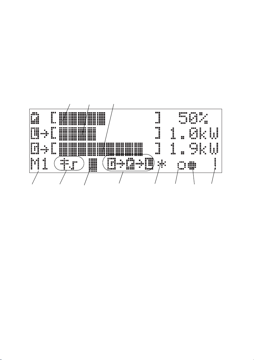
SMA Solar Technology AG Operating the Sunny Island
10.2.2 Standard View 2
The standard view 2 shows the operating states of the Sunny Island:
• Battery charge power
•Output power
• Power from the grid/generator
as well as various information items on the status line.
A
D
E
B
F
C
G
A Battery charge level in [%]
B Output power of consumers in [kW]
C Power drawn from the grid/generator (AC2) in [kW]
D Device hierarchy (master, slave 1, slave 2)
E grid/generator limits
F MMC/SD card in use
G Direction of energy flow and system status
H Status of grid/generator (alternates with GenReq)
IRelay 1 Status
JRelay 2 Status
K Warning message
H
I
K
J
Technical Description SI2012_2224-TEN082311 93
Page 94

Operating the Sunny Island SMA Solar Technology AG
Row 1
The bar shows the charge state of the battery
in [%]
The value of the charge state is also shown
digitally on the right.
[¿¿¿¿¿ ] 50%
Row 2
The bar shows the magnitude of the totall
output power in [kW] with which the
consumers are being supplied.
The arrow to the right, next to the describes
the direction of energy flow:
• ‡ Loads are being supplied
• † Sunny Boy (PV inverter) feeds into the
grid
The magnitude of the total output power [kW]
is also shown to the right digitally.
‡[¿¿¿¿ ] 1.0kW
Row 3
The bar shows the magnitude of the power
drawn fromt the grid/generator in [kW].
The arrow to the right, next to the describes
the direction of energy flow:
• ‡ The island grid system is being
supplied by the grid/generator
The magnitude of the total power [kW] is also
shown to the right digitally.
‡[¿¿¿¿¿¿¿¿¿ ] 1.9kW
Row 4 (status bar)
The following information is shown in the
status bar (from left to right):
1. Device hierarchy
• M1 = Master
• S1 = Slave1
• S2 = Slave2
M1 ¿ ‡‡ * oo !
94 SI2012_2224-TEN082311 Technical Description
Page 95

SMA Solar Technology AG Operating the Sunny Island
2. Connection to the public grid/a generator:
• = the Sunny Island monitors the grid limits (grid operation)
• x = the Sunny Island monitors the generator limits (operation with generator)
3. MMC/SD card (memory card) in the Sunny Remote Control 1:
• ¿ = card inserted
• = card missing
4. These indicators label the energy flow direction of the
• = grid/generator
• = battery
• = Consumers
There are four operative states:
• ‡‡ = the grid/generator charges the battery and supplies the consumers
• ‡‡‡ = the grid/generator supplies the consumers
• ‡ = the grid/generator charges the battery, there are no consumers connected
• ‡ = the battery supplies the consumers
5. The state of the external sources are described by the following symbols:
• * = The grid/generator voltage and frequency are within the set limits
• ? = Generator voltage and/or frequency are outside of the set limits. The Sunny
Island will not connect the generator to the stand-alone grid while this situation exists.
• ! = The maximal admissible grid/generator reverse power was exceeded, the
Sunny Island has disconnected the grid/generator from the stand-alone grid.
The following characters indicate why the generator was deployed:
• B = Battery = The generator was deployed due to the battery's state of charge.
• L = Load = The generator was deployed due to a load-dependent generator
requirement.
• S = Start = The generator was deployed due to the operator's manual switching of
the generator activation on the Sunny Island from "Auto" to "Start". The generator is
no longer controlled automatically nor switched off by the Sunny Island.
• T = Time = The generator was run for an hour by the Sunny Island via the parameter
setting "Run1h". After this period the Sunny Island switches off the generator
automatically.
Technical Description SI2012_2224-TEN082311 95
Page 96
Operating the Sunny Island SMA Solar Technology AG
The display changes
The generator status and the reason for its deployment are shown (alternating)
under "Generator-Status" in the display.
• If, for example, the display changes every 3 seconds from "*" to "B", this
means that the generator voltage and frequency lie within the specified limits
and that the generator was requested as a result of the battery charge level.
• If the generator has been manually set to "Stop", then no generator status
information is shown on the display. The field remains empty.
6. Relays
= relay activated
o = relay deactivated
7. Warning:
! = Warning
The symbol blinks until you have seen and cleared the warning in menu "410# Fail
Current" or "420# Fail History".
Faults: If there is a fault, the device goes into standby. A fault notice appears on the
display. Acknowledge and clear the fault; then the Sunny Island can be restarted.
Change to Standard View 1
The display switches to standard view 1 (home screen) automatically if the Sunny Remote
Control 1 has not been used for more than five minutes (inactivity).
Display Illumination
The background illumination is automatically deactivated after a short time of inactivity.
Switch the lighting back on by turning the pushbutton slightly. This turning changes no
settings; it only reactivates the display illumination.
Message Displays
Messages are displayed at all times during operation, they have priority over the
standard view 1 (home screen).
96 SI2012_2224-TEN082311 Technical Description
Page 97
SMA Solar Technology AG Operating the Sunny Island
10.2.3 Select menu
You can navigate the Sunny Island's menus with the external display's (Sunny Remote Control 1)
pushbutton.
• By pressing the pushbutton, you reach a submenu level.
• By turning the pushbutton you can move within this menu level.
• By selecting the line "back" and pressing the pushbutton, you leave the menu level you are in
and move to the next higher level.
Example:
The display shows the standard view 1. Browse
through the main menu by turning the pushbutton
right or left.
1. Turn the pushbutton to the right.
The display's background lighting is
activated.
2. Turn the pushbutton further to the right.
The display shows the standard view 2.
15:15:38
2.0 kW 1.5 kW
‡ ----+---- ‡
50% Š -0.5 kW
[¿¿¿¿¿ ] 50%
‡[¿¿¿¿ ] 1.5kW
‡[¿¿¿¿¿¿¿¿¿ ] 2.0kW
M1 ¿ ‡‡ * oo !
3. Turn the pushbutton further to the right.
The following display appears:
100# Meters
200# Settings
To the left are the menu number and name.
That line is active on which, to the far right,
300# Diagnosis
400# Failure/Event
the enter arrow is shown.
4. Depress the knob.
The arrow jumps to the submenu of the
"100# Meters" main menu item.
110# Meter Inverter
120# Meter Battery
130# Meter Backup
150# Meter Compact
Technical Description SI2012_2224-TEN082311 97
Page 98
Operating the Sunny Island SMA Solar Technology AG
5. Depress the pushbutton.
The arrow jumps one menu level further.
Now you have three possibilities:
- Depress the pushbutton. The arrow
jumps one level further. You can see
parameters which are assigned to this
menu.
- Select the line "back". To do this turn the
pushbutton left or right until the "enter"
arrow is on the appropriate line.
Then press the pushbutton.
- Select the line "home". Press the
pushbutton. Now you can see the
standard view 1.
Sequence of the Menu Items
Menu items can be skipped over, i.e., you do not see all numbered parameters. This is
related to the password level which is set. If you are using the device in user level, those
parameters which should only be set by the installer do not appear. The menu numbers
are fixed, that means they do not change if an entry (or several entries) are skipped.
111# Meter Total
112# Meter Device
[<-- back]
[<-- home]
98 SI2012_2224-TEN082311 Technical Description
Page 99
SMA Solar Technology AG Operating the Sunny Island
10.2.4 Selecting Parameters
Parameters are shown on the display as follows:
• To the left are the menu number and the
parameter number. To the right, a bar
shows the status of the value queried at
present.
• To the left is the parameter name and to the
right the "enter" arrow . The arrow
indicates that this parameter can be
adjusted.
• Magnitude and units.
Syntax for this document
The syntax specified here for menus and parameters applies throughout the entire
document.
A menu is marked by a hash mark, menu number and menu names
(130# Meter Backup).
A parameter is marked with a menu number, dot (hash, on the display), parameter
number and parameter name (131.01 TotExtPwrAt).
210#01 ¿
InvVtgNom
230.0 [V]
10.2.5 Selecting Events
The event list is found in the main menu, under 400# Failure/Event. Then go to the submenu 1 and
activate 430# Event.
Events are shown on the display as follows:
• To the left are the menu number and name.
To the right is the total number of events.
• Date and time of the event.
• Event and number (see chapter 18.5
"Events" (Page 185)).
• Description of the event
Technical Description SI2012_2224-TEN082311 99
430# Event 001
2007-04-17 11:55:01
E101 ---
Silent
Page 100

Operating the Sunny Island SMA Solar Technology AG
Skip back to the previous menu level:
• Turn the pushbutton completely to the left
or right until "back" is shown on the
430# Event
[<-- back]
display.
• Press the pushbutton
10.2.6 Selecting Warnings and Faults
The warnings and faults list can be found in the main menu under 400# Failure/Event. Then go to
the submenu 1.
• List of the current warnings and faults - 410# Fail Current.
• List of all warnings and faults (history) - 420# Fail History
Example:
Warnings and faults are shown on the display as
follows:
• To the left are the menu number and name.
To the right is the total number of instances
for this particular warning or fault, to date.
• Date and time of the warning/fault.
• Warning or Fault and number (see chapter
18.7 "Warnings and Failure messages"
(Page 188)). The "enter" arrow shows that
the fault must be cleared and confirmed
thereafter. Only thereafter can the Sunny
Island be restarted.
• Description of the warning/fault.
410# Pending 002
2007-04-17 11:55:01
W212 Warning
BatTempHigh
Pending: The warning/fault is pending.
The fault has not yet been cleared.
Arrive: Time at which the warning/fault
appeared.
Clear: The warning/fault has been
cleared.
100 SI2012_2224-TEN082311 Technical Description
 Loading...