

Page 1
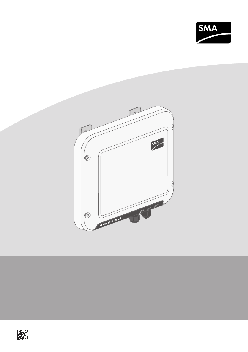
SUNNY BOY STORAGE 2.5
SBS2.5-1VL-10
ENGLISH
ESPAÑOL
ITALIANO
Quick Reference Guide
Instrucciones breves
Guida rapida
DEUTSCH
FRANÇAIS
SBS25-1VL-10-IS-xx-14 | 102126-00.02 | Version 1.4
Schnelleinstieg
Notice résumée
Page 2
ENGLISH
1 Intended Use
SMA Solar Technology AG
1 Intended Use
The SunnyBoyStorage is a single-phase, AC coupled battery inverter for parallel grid operation.
The SunnyBoyStorage converts the direct current supplied by a battery into grid-compliant
alternating current. With a lithium-ion battery and the energy meter, the SunnyBoyStorage
becomes a system for increased self-consumption.
The SunnyBoyStorage must only be operated in connection with an intrinsically safe lithium-ion
battery approved by SMA Solar Technology AG. An updated list of batteries approved by SMA
Solar Technology AG is available at www.SMA-Solar.com.
The lithium-ion battery must comply with the locally applicable standards and directives and must
be intrinsically safe (see technical information "SMA Flexible Storage System - Detailed
explanations of the safety concept" for detailed explanations regarding the safety concept of
battery inverters by SMA Solar Technology AG). The battery management of the used lithium-ion
battery must be compatible with the Sunny Boy Storage. The entire battery voltage range must be
completely within the permissible input voltage range of the SunnyBoyStorage. The maximum
permissible DC input voltage of the SunnyBoyStorage must not be exceeded.
The SunnyBoyStorage is suitable for indoor and outdoor use.
The Sunny Boy Storage is not suitable for supplying life-sustaining medical devices. A power outage
must not lead to personal injury.
All components must remain within their permitted operating ranges and their installation
requirements at all times.
The product must only be used in countries for which it is approved or released by SMA Solar
Technology AG and the grid operator.
Use this product only in accordance with the information provided in the enclosed documentation
and with the locally applicable standards and directives. Any other application may cause
personal injury or property damage.
Alterations to the product, e.g. changes or modifications, are only permitted with the express written
permission of SMA Solar Technology AG. Unauthorized alterations will void guarantee and
warranty claims and in most cases terminate the operating license. SMA Solar Technology AG
shall not be held liable for any damage caused by such changes.
Any use of the product other than that described in the Intended Use section does not qualify as
appropriate.
The enclosed documentation is an integral part of this product. Keep the documentation in a
convenient place for future reference and observe all instructions contained therein.
The type label must remain permanently attached to the product.
2 Symbols
Danger to life due to electric shock
The product operates at high voltages. All work on the product must be
carried out by electrically qualified persons only.
Quick Reference GuideSBS25-1VL-10-IS-xx-142
Page 3
SMA Solar Technology AG
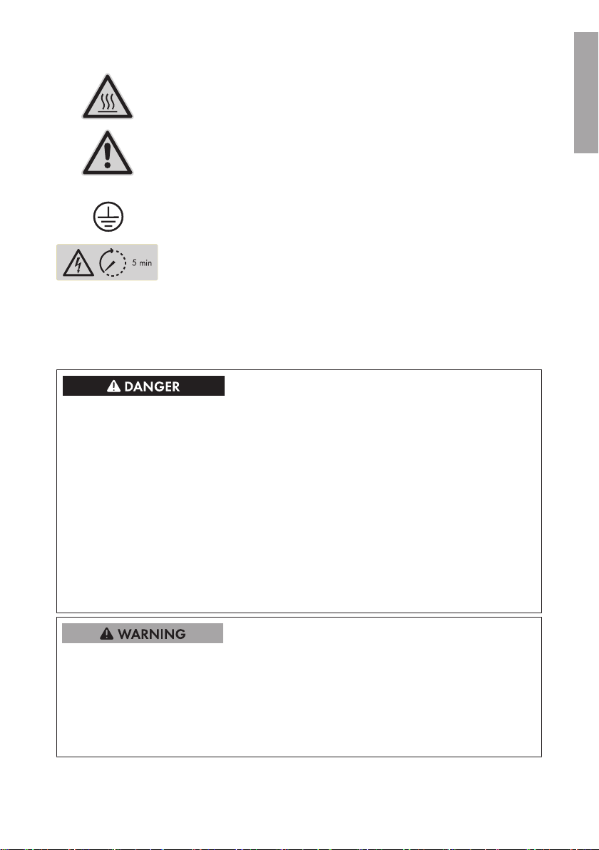
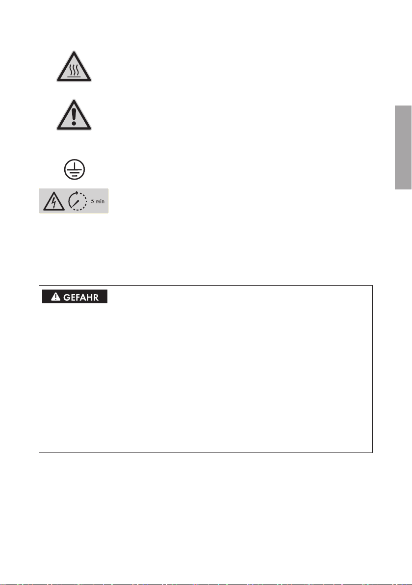
Risk of burns due to hot surfaces
The product can get hot during operation. Avoid contact during operation.
Allow the product to cool down sufficiently before carrying out any work.
Notice
This symbol indicates general dangers. In this case, it indicates that the inverter must be additionally grounded if local conditions require additional
grounding or equipotential bonding.
Grounding conductor
This symbol indicates the position for connecting a grounding conductor.
Danger to life due to high voltages in the inverter; observe a waiting time of five minutes
High voltages that can cause lethal electric shocks are present in live components inside the inverter. Always disconnect the inverter from voltage
sources before performing any work on it.
3 Safety Information
3 Safety Information
Danger to life from electric shock due to live DC cables at the battery.
The DC cables connected to a battery are live. Touching the DC conductors or the live
components leads to lethal electric shocks.
• Do not touch non-insulated cable ends.
• Do not touch the DC conductors.
• Do not touch any live components.
• Have the inverter and the battery mounted, installed and commissioned only by qualified
persons with the appropriate skills.
• Observe all safety information of the battery manufacturer.
• Prior to performing any work on the inverter or the battery, disconnect the inverter from all
voltage sources as described in this document.
• If an error occurs, have it rectified by qualified persons only.
ENGLISH
Risk of injury due to short-circuit currents
Short-circuit currents in the battery can cause heat build-up and electric arcs. Burns or eye injuries
due to flashes may result.
• Remove watches, rings and other metal objects.
• Use insulated tools.
• Do not place tools or metal parts on the battery.
Quick Reference Guide 3SBS25-1VL-10-IS-xx-14
Page 4
ENGLISH
4 Installation
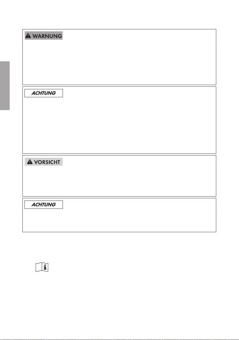
Damage to the battery due to incorrect settings
The set battery parameters influence the charging behavior of the inverter. The battery can be
damaged by incorrect settings of the battery type, nominal voltage and capacity parameters.
• Set the correct battery type as well as the correct values for nominal voltage and battery
capacity when configuring.
• Ensure that the values recommended by the manufacturer are set for the battery (refer to the
technical data of the battery in the manufacturer documentation).
Risk of burns due to hot enclosure parts
Some parts of the enclosure can get hot during operation.
• Mount the inverter in such a way that it cannot be touched inadvertently during operation.
Damage to the inverter due to the use of cleaning agents
• If the inverter is dirty, clean the enclosure, the enclosure lid, the type label and the LEDs using
only clean water and a cloth.
SMA Solar Technology AG
4 Installation
Carry out the actions illustrated graphically in this document in the specified order and observe all
information.
You can find a detailed installation manual for installation and commissioning
as well as a user manual for configuration and troubleshooting at www.SMASolar.com.
5 Declaration of Conformity
EC Declaration of conformity (valid until April 19, 2016)
within the scope of the EU directives
• Electromagnetic compatibility 2004/108/EC (EMC)
• Low Voltage Directive 2006/95/EC (LVD)
• Radio and telecommunications terminal equipment (R&TTE) 1999/05/EC
SMA Solar Technology AG confirms herewith that the inverters described in this document are in
compliance with the fundamental requirements and other relevant provisions of the abovementioned directives. The entire EC Declaration of Conformity can be found at www.SMASolar.com.
Quick Reference GuideSBS25-1VL-10-IS-xx-144
Page 5
SMA Solar Technology AG
5 Declaration of Conformity
EC Declaration of conformity (valid from April 20, 2016)
within the scope of the EU directives
• Electromagnetic compatibility 2004/30/EU (L 96/79-106, March 29,
2014) (EMC)
• Low Voltage Directive 2014/35/EU (L 96/357-374, March 29, 2014)
(LVD)
• Radio and telecommunications terminal equipment (R&TTE) 1999/05/EC
SMA Solar Technology AG confirms herewith that the inverters described in this document are in
compliance with the fundamental requirements and other relevant provisions of the abovementioned directives. The entire EC Declaration of Conformity can be found at www.SMASolar.com.
ENGLISH
Quick Reference Guide 5SBS25-1VL-10-IS-xx-14
Page 6
DEUTSCH
1 Bestimmungsgemäße Verwendung
SMA Solar Technology AG
1 Bestimmungsgemäße Verwendung
Der Sunny Boy Storage ist ein 1-phasiger, AC-gekoppelter Batterie-Wechselrichter für den
Netzparallelbetrieb. Der Sunny Boy Storage wandelt den von einer Batterie gelieferten Gleichstrom
in netzfähigen Wechselstrom. Der Sunny Boy Storage ergibt zusammen mit einer Lithium-IonenBatterie und dem Energiezähler ein System zur Eigenverbrauchsoptimierung.
Der Sunny Boy Storage darf nur in Verbindung mit einer von SMA Solar Technology AG
freigegebenen, eigensicheren Lithium-Ionen-Batterie betrieben werden. Eine aktualisierte Liste der
von SMA Solar Technology AG freigegebenen Batterien finden Sie unter www.SMA-Solar.com.
Die Lithium-Ionen-Batterie muss den vor Ort gültigen Normen und Richtlinien entsprechen und muss
eigensicher sein (Erläuterungen zum Sicherheitskonzept eines Batterie-Wechselrichter von SMA
Solar Technology AG siehe Technische Information "SMA Flexible Storage System - Erläuterungen
zum Sicherheitskonzept"). Das Batteriemanagement der eingesetzten Lithium-Ionen-Batterie muss
kompatibel zum Sunny Boy Storage sein. Der gesamte Batteriespannungsbereich muss vollständig
innerhalb des zulässigen Eingangsspannungsbereichs des Sunny Boy Storage liegen. Die maximal
zulässige DC-Eingangsspannung des Sunny Boy Storage darf nicht überschritten werden.
Der Sunny Boy Storage ist für den Einsatz im Außenbereich und Innenbereich geeignet.
Der Sunny Boy Storage ist nicht für die Versorgung von lebenserhaltenden medizinischen Geräten
geeignet. Ein Stromausfall darf zu keinem Personenschaden führen.
Der erlaubte Betriebsbereich und die Installationsanforderungen aller Komponenten müssen
jederzeit eingehalten werden.
Das Produkt darf nur in Ländern eingesetzt werden, für die es zugelassen oder für die es durch
SMA Solar Technology AG und den Netzbetreiber freigegeben ist.
Setzen Sie das Produkt ausschließlich nach den Angaben der beigefügten Dokumentationen und
gemäß der vor Ort gültigen Normen und Richtlinien ein. Ein anderer Einsatz kann zu Personenoder Sachschäden führen.
Eingriffe in das Produkt, z. B. Veränderungen und Umbauten, sind nur mit ausdrücklicher
schriftlicher Genehmigung von SMA Solar Technology AG gestattet. Nicht autorisierte Eingriffe
führen zum Wegfall der Garantie- und Gewährleistungsansprüche sowie in der Regel zum
Erlöschen der Betriebserlaubnis. Die Haftung von SMA Solar Technology AG für Schäden aufgrund
solcher Eingriffe ist ausgeschlossen.
Jede andere Verwendung des Produkts als in der bestimmungsgemäßen Verwendung beschrieben
gilt als nicht bestimmungsgemäß.
Die beigefügten Dokumentationen sind Bestandteil des Produkts. Die Dokumentationen müssen
gelesen, beachtet und jederzeit zugänglich aufbewahrt werden.
Das Typenschild muss dauerhaft am Produkt angebracht sein.
2 Symbole
Lebensgefahr durch elektrischen Schlag
Das Produkt arbeitet mit hohen Spannungen. Alle Arbeiten am Produkt dürfen ausschließlich durch Elektrofachkräfte erfolgen.
SchnelleinstiegSBS25-1VL-10-IS-xx-146
Page 7
SMA Solar Technology AG
Verbrennungsgefahr durch heiße Oberfläche
Das Produkt kann während des Betriebs heiß werden. Vermeiden Sie
Berührungen während des Betriebs. Lassen Sie vor allen Arbeiten das Produkt ausreichend abkühlen.
Achtung
Dieses Symbol warnt vor allgemeinen Gefahren. In diesem Fall weist es
darauf hin, dass der Wechselrichter zusätzlich geerdet werden muss,
wenn vor Ort eine zusätzliche Erdung oder ein Potenzialausgleich
gefordert ist.
Schutzleiter
Dieses Symbol kennzeichnet den Ort für den Anschluss eines Schutzleiters.
Lebensgefahr durch hohe Spannungen im Wechselrichter,
Wartezeit von 5 Minuten einhalten
An den spannungsführenden Bauteilen im Inneren des Wechselrichters
liegen hohe Spannungen an, die lebensgefährliche Stromschläge verursachen können. Vor allen Arbeiten am Wechselrichter den Wechselrichter
immer spannungsfrei schalten.
3 Sicherheitshinweise
3 Sicherheitshinweise
DEUTSCH
Lebensgefährlicher Stromschlag durch spannungsführende DC-Kabel an der Batterie
Die DC-Kabel, die an einer Batterie angeschlossen sind, stehen unter Spannung. Das Berühren
der DC-Leiter oder der spannungsführenden Bauteile verursacht lebensgefährliche Stromschläge.
• Keine freiliegenden Kabelenden berühren.
• Die DC-Leiter nicht berühren.
• Keine spannungsführenden Bauteile berühren.
• Den Wechselrichter und die Batterie ausschließlich von Fachkräften mit entsprechender
Qualifikation montieren, installieren und in Betrieb nehmen lassen.
• Alle Sicherheitshinweise des Batterieherstellers einhalten.
• Vor allen Arbeiten am Wechselrichter und an der Batterie den Wechselrichter immer wie in
diesem Dokument beschrieben spannungsfrei schalten.
• Wenn ein Fehler auftritt, den Fehler ausschließlich von Fachkräften beheben lassen.
Schnelleinstieg 7SBS25-1VL-10-IS-xx-14
Page 8
DEUTSCH
4 Installation
Verletzungsgefahr durch Kurzschluss-Ströme
Kurzschluss-Ströme der Batterie können Hitzeentwicklungen und Lichtbögen verursachen.
Verbrennungen oder Augenverletzungen durch Lichtblitze können die Folge sein.
• Uhren, Ringe und andere Metallobjekte ablegen.
• Isoliertes Werkzeug verwenden.
• Keine Werkzeuge oder Metallteile auf die Batterie legen.
Beschädigung der Batterie durch fehlerhafte Einstellungen
Die für die Batterie eingestellten Parameter beeinflussen das Ladeverhalten des Wechselrichters.
Die Batterie kann durch falsche Einstellungen der Parameter für Batterietyp, Nennspannung der
Batterie und Batteriekapazität beschädigt werden.
• Bei der Konfiguration den korrekten Batterietyp und die korrekten Werte für Nennspannung
und Batteriekapazität einstellen.
• Sicherstellen, dass die vom Hersteller empfohlenen Werte für die Batterie eingestellt sind
(Technische Daten der Batterie siehe Dokumentation des Batterieherstellers).
Verbrennungsgefahr durch heiße Gehäuseteile
Gehäuseteile können während des Betriebs heiß werden.
• Den Wechselrichter so montieren, dass während des Betriebs ein versehentliches Berühren
nicht möglich ist.
SMA Solar Technology AG
Beschädigung des Wechselrichters durch Verwendung von Reinigungsmitteln
• Wenn der Wechselrichter verschmutzt ist, reinigen Sie das Gehäuse, den Gehäusedeckel,
das Typenschild und die LEDs ausschließlich mit klarem Wasser und einem Tuch.
4 Installation
Führen Sie die in diesem Dokument grafisch dargestellten Handlungen in der vorgegebenen
Reihenfolge aus und beachten Sie alle Hinweise.
Eine ausführliche Installationsanleitung zur Installation und Inbetriebnahme
sowie eine Bedienungsanleitung zur Konfiguration und Fehlerbehebung finden
Sie unter www.SMA-Solar.com.
SchnelleinstiegSBS25-1VL-10-IS-xx-148
Page 9
SMA Solar Technology AG
5 Konformitätserklärung
EG-Konformitätserklärung (gültig bis 19.04.2016)
im Sinne der EU-Richtlinien
• Elektromagnetische Verträglichkeit 2004/108/EG (EMV)
• Niederspannung 2006/95/EG (NSR)
• Funkanlagen und Telekommunikationsendeinrichtungen 1999/05/EG
(R&TTE)
5 Konformitätserklärung
Hiermit erklärt SMA Solar Technology AG, dass sich die in diesem Dokument beschriebenen
Wechselrichter in Übereinstimmung mit den grundlegenden Anforderungen und anderen relevanten
Bestimmungen der oben genannten Richtlinien befinden. Die vollständige EG-Konformitätserklärung
finden Sie unter www.SMA-Solar.com.
EU-Konformitätserklärung (gültig ab 20.04.2016)
im Sinne der EU-Richtlinien
• Elektromagnetische Verträglichkeit 2004/30/EU
(29.3.2014L96/79-106) (EMV)
• Niederspannung 2014/35/EU (29.3.2014L96/357-374) (NSR)
• Funkanlagen und Telekommunikationsendeinrichtungen 1999/05/EG
(R&TTE)
Hiermit erklärt SMA Solar Technology AG, dass sich die in diesem Dokument beschriebenen
Wechselrichter in Übereinstimmung mit den grundlegenden Anforderungen und anderen relevanten
Bestimmungen der oben genannten Richtlinien befinden. Die vollständige EU-Konformitätserklärung
finden Sie unter www.SMA-Solar.com.
DEUTSCH
Schnelleinstieg 9SBS25-1VL-10-IS-xx-14
Page 10
ESPAÑOL
1 Uso previsto
SMA Solar Technology AG
1 Uso previsto
El Sunny Boy Storage es un inversor con batería monofásico, acoplado a la CA para el
funcionamiento simultáneo de la red El SunnyBoyStorage transforma la corriente continua
suministrada por una batería en corriente alterna apta para la red. El Sunny Boy Storage
compone, junto con una batería de iones de litio y el contador de energía, un sistema para
optimizar el autoconsumo.
El Sunny Boy Storage debe utilizarse solamente en conexión con una batería de iones de litio de
SMA Solar Technology AG aprobada y de seguridad intrínseca. Encontrará un listado actualizado
de las baterías aprobadas por SMA Solar Technology AG en www.SMA-Solar.com.
La batería de iones de litio debe cumplir con las normativas y directivas vigentes en el lugar y
contar con seguridad intrínseca (para obtener información sobre el sistema de seguridad de un
inversor con batería de SMA Solar Technology AG, consulte la información técnica “SMA Flexible
Storage System - Detailed explanations of the safety concept”). La gestión avanzada de baterías
de la batería de iones de litio empleada debe ser compatible con Sunny Boy Storage. El rango de
tensión de la batería debe encontrarse por completo dentro del rango de tensión de entrada
permitido del SunnyBoyStorage. No debe sobrepasarse la tensión de entrada deCC máxima
permitida del SunnyBoyStorage.
El SunnyBoyStorage es apto para el uso en interiores y exteriores.
El SunnyBoyStorage no es apto para la alimentación de equipos médicos de soporte vital. Un
apagón no debe causar daños a personas.
Deben respetarse en todo momento el rango de funcionamiento admisible y los requisitos de
instalación de todos los componentes.
El producto solo debe utilizarse en los países donde esté autorizado o para los que haya sido
aprobado por SMA Solar Technology AG y el operador de red.
Utilice siempre el producto de acuerdo con las indicaciones de la documentación adjunta y
observe las normativas y directivas locales vigentes. Cualquier otro uso puede causar lesiones al
usuario o daños materiales.
Para realizar cualquier intervención en el producto, como modificaciones o remodelaciones,
deberá contar con el permiso expreso y por escrito de SMA Solar Technology AG. Los cambios no
autorizados pueden conducir a la pérdida de los derechos de garantía así como a la extinción de
la autorización de operación. Queda excluida la responsabilidad de SMA Solar Technology AG
por los daños derivados de dichos cambios.
Cualquier uso del producto distinto al descrito en el uso previsto se considerará inadecuado.
La documentación adjunta forma parte del producto. La documentación debe leerse, observarse y
guardarse en un lugar accesible en todo momento.
La placa de características debe estar en el producto en todo momento.
2 Símbolos
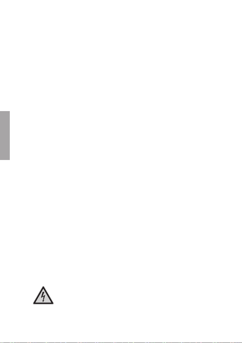
Peligro de muerte por descarga eléctrica
El producto funciona con altas tensiones. Los trabajos en el producto
deben ser llevados a cabo exclusivamente por instaladores eléctricos.
Instrucciones brevesSBS25-1VL-10-IS-xx-1410
Page 11
SMA Solar Technology AG
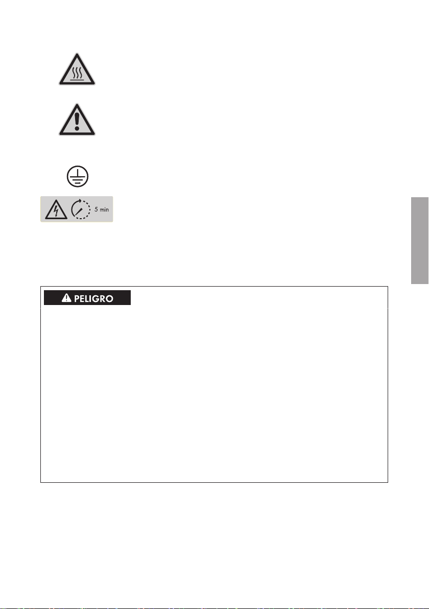
Peligro de quemaduras por superficies calientes
El producto puede calentarse durante el funcionamiento. Procure no tocarlo mientras está funcionando. Antes de llevar a cabo cualquier trabajo
en el producto, espere a que se enfríe lo suficiente.
Precaución
Este símbolo advierte de peligros generales. En este caso advierte de que
el inversor debe tener una conexión a tierra adicional si en el lugar de instalación se requiere una toma a tierra adicional o una conexión equipotencial.
Conductor de protección
Este símbolo señaliza el lugar para conectar un conductor de protección.
Peligro de muerte por altas tensiones en el inversor; respetar el
tiempo de espera de 5minutos
En los componentes conductores del interior del inversor existen altas tensiones que pueden causar descargas eléctricas mortales. Antes de efectuar cualquier trabajo en el inversor, desconéctelo siempre de la tensión.
3 Indicaciones de seguridad
3 Indicaciones de seguridad
Peligro de muerte por descarga eléctrica causada por cables de CC bajo tensión en la
batería
Los cables de CC conectados a una batería se encuentran bajo tensión. El contacto con los
conductores de CC o los componentes conductores causa descargas eléctricas que pueden ser
mortales.
• No toque ningún extremo de cable descubierto.
• No toque los conductores de CC.
• No toque ningún componente bajo tensión.
• Encargue el montaje, la instalación y la puesta en marcha del inversor y de la batería
únicamente a especialistas con la cualificación adecuada.
• Siga todas las indicaciones de seguridad del fabricante de las baterías.
• Antes de efectuar cualquier trabajo en el inversor y en la batería, desconecte el inversor de
la tensión tal y como se describe en este documento.
• Si se produce un error, deje que lo resuelva exclusivamente un especialista.
ESPAÑOL
Instrucciones breves 11SBS25-1VL-10-IS-xx-14
Page 12
ESPAÑOL
4 Instalación
Peligro de lesión por corrientes de cortocircuito
Las corrientes de cortocircuito de la batería pueden originar subidas de temperatura y arcos
voltaicos. Esto puede causar quemaduras o lesiones en los ojos por destellos.
• No lleve relojes, anillos u otros objetos de metal.
• Utilice una herramienta aislada.
• No ponga herramientas o piezas de metal sobre la batería.
Daños en la batería debido a una configuración errónea
Los parámetros ajustados para la batería afectan al comportamiento de carga del inversor. Un
ajuste erróneo de los parámetros para el tipo de batería, su tensión nominal y su capacidad
puede dañar la batería.
• Durante la configuración, ajuste el tipo de batería adecuado y los valores correctos de
tensión nominal y capacidad de la batería.
• Asegúrese de que estén ajustados los valores recomendados por el fabricante de la batería
(para más información sobre la batería, consulte la documentación del fabricante).
Peligro de quemaduras por contacto con las partes calientes de la carcasa
Las partes de la carcasa pueden calentarse durante el funcionamiento.
• Monte el inversor de manera que no sea posible un contacto accidental con la carcasa
durante el funcionamiento.
SMA Solar Technology AG
Daños en el inversor debido al uso de productos de limpieza
• Si el inversor está sucio, limpie la carcasa, la tapa de la carcasa, la placa de características
y los leds únicamente con agua limpia y un paño.
4 Instalación
Siga los pasos representados con imágenes en este documento en el orden indicado y tenga en
cuenta todas las indicaciones.
En www.SMA-Solar.com encontrará las instrucciones de instalación detalladas
para la instalación y puesta en marcha así como las instrucciones de uso para
la configuración y la eliminación de error.
Instrucciones brevesSBS25-1VL-10-IS-xx-1412
Page 13
SMA Solar Technology AG
5 Declaración de conformidad
5 Declaración de conformidad
Declaración de conformidad CE (válida hasta el 19/04/2016)
En virtud de las directivas europeas
• Compatibilidad electromagnética 2004/108/EG (CEM)
• Baja tensión 2006/95/CE (DBT)
• Equipos radioeléctricos y equipos terminales de telecomunicación
1999/05/CE (R&TTE)
Por la presente, SMA Solar Technology AG declara que los inversores descritos en este
documento cumplen los requisitos básicos y cualquier otra disposición relevante de las directivas
mencionadas anteriormente. Encontrará la declaración de conformidadCE completa en
www.SMA-Solar.com.
Declaración de conformidad CE (válida a partir del 20/04/2016)
En virtud de las directivas europeas
• Compatibilidad electromagnética 2004/30/UE (29/3/2014 L
96/79-106) (CEM)
• Baja tensión 2014/35/UE (29/3/2014 L96/357-374) (DBT)
• Equipos radioeléctricos y equipos terminales de telecomunicación
1999/05/CE (R&TTE)
Por la presente, SMA Solar Technology AG declara que los inversores descritos en este
documento cumplen los requisitos básicos y cualquier otra disposición relevante de las directivas
mencionadas anteriormente. Encontrará la declaración de conformidadUE completa en
www.SMA-Solar.com.
ESPAÑOL
Instrucciones breves 13SBS25-1VL-10-IS-xx-14
Page 14
FRANÇAIS
1 Utilisation conforme
SMA Solar Technology AG
1 Utilisation conforme
Le SunnyBoy Storage est un onduleur/chargeur monophasé à couplage AC pour l'exploitation
réseau en parallèle. Le SunnyBoy Storage transforme le courant continu de batteries en courant
alternatif conforme à celui du réseau. Le SunnyBoy Storage, y compris une batterie lithium-ion et un
compteur d’énergie, constitue un système pour l’optimisation de l’autoconsommation.
Le SunnyBoy Storage doit être mis en service uniquement en combinaison avec une batterie lithiumion à sécurité intrinsèque autorisée par SMA Solar Technology AG. Vous trouverez une liste à jour
des batteries autorisées par SMA Solar Technology AG sur www.SMA-Solar.com.
La batterie lithium-ion doit correspondre aux normes et directives en vigueur sur le site et présenter
une sécurité intrinsèque (Explications sur le système de sécurité de l’onduleur/chargeur de SMA
Solar Technology AG, voir information technique «SMA Flexible Storage System - Detailed
explanations of the safety concept»). La gestion de la batterie lithium-ion utilisée doit être
compatible avec le SunnyBoy Storage. Toute la plage de tension de la batterie doit se situer
entièrement dans la plage de tension d’entrée autorisée du SunnyBoy Storage. La tension
d’entréeDC maximale autorisée du SunnyBoy Storage ne doit pas être dépassée.
Le SunnyBoy Storage convient pour l’utilisation à l’extérieur et à l’intérieur.
Le SunnyBoy Storage ne convient pas à l’alimentation de dispositifs médicaux d'assistance à la vie.
Une panne de courant ne doit entraîner aucun dommage corporel.
La plage de fonctionnement autorisée et les exigences pour les installations de tous les composants
doivent être respectées en toutes circonstances.
Le produit ne doit être utilisé que dans les pays pour lesquels il est homologué ou pour lesquels il a
été autorisé par SMA Solar Technology AG et par l’exploitant de réseau.
Utilisez ce produit exclusivement en conformité avec la documentation fournie ainsi qu’avec les
normes et directives en vigueur sur le site. Tout autre usage peut compromettre la sécurité des
personnes ou entraîner des dommages matériels.
Les interventions sur le produit (modifications ou transformations, par exemple) ne sont autorisées
qu’après accord écrit de SMA Solar Technology AG. Toute intervention non autorisée entraîne
l’annulation de la garantie légale et commerciale et, en règle générale, le retrait de l’autorisation
d’exploitation. SMA Solar Technology AG décline toute responsabilité en cas de dommages
résultant d’une telle intervention.
Toute utilisation du produit différente de celle décrite dans l’utilisation conforme est considérée
comme non conforme.
Les documents joints font partie intégrante du produit. Les documents doivent être lus, respectés et
rester accessibles à tout moment.
La plaque signalétique doit être apposée en permanence sur le produit.
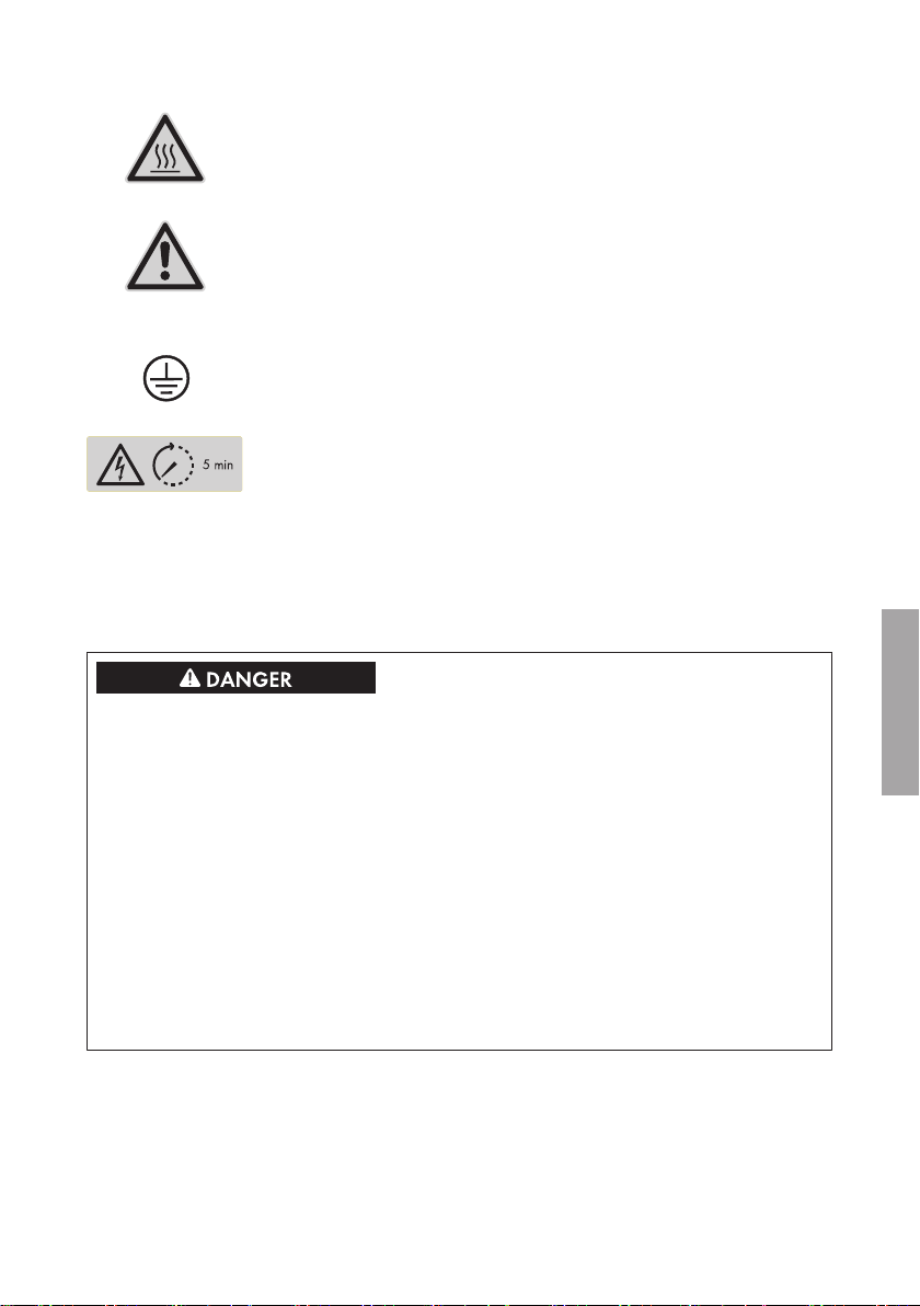
2 Symboles
Danger de mort par choc électrique
Le produit fonctionne avec des tensions élevées. Toute intervention sur le
produit doit être effectuée exclusivement par du personnel qualifié en électricité.
Notice résuméeSBS25-1VL-10-IS-xx-1414
Page 15
SMA Solar Technology AG
Risque de brûlure au contact de surfaces brûlantes
Au cours du fonctionnement, le produit peut devenir brûlant. Évitez tout
contact avec l’appareil pendant le fonctionnement. Laissez le produit refroidir suffisamment avant toute intervention.
Prudence
Ce symbole met en garde contre des dangers généraux. Dans ce cas, le
symbole indique que l’onduleur doit être mis à la terre de façon supplémentaire si une mise à la terre supplémentaire ou une liaison équipotentielle est nécessaire sur place.
Conducteur de protection
Ce symbole signale l’emplacement du raccordement de conducteur de
protection.
Danger de mort dû à de hautes tensions dans l’onduleur, respecter un délai d’attente de cinqminutes
Les composants conducteurs de courant à l’intérieur de l’onduleur sont
soumis à de hautes tensions qui peuvent provoquer des chocs électriques
susceptibles d’entraîner la mort. Avant de commencer tout travail sur l’onduleur, mettez toujours l’onduleur hors tension.
3 Consignes de sécurité
3 Consignes de sécurité
Danger de mort par choc électrique dû à des câblesDC conducteurs au niveau de la
batterie
Les câbles DC raccordés à la batterie sont sous tension. Le contact avec les conducteurs DC ou
composants conducteurs provoque des chocs électriques susceptibles d’entraîner la mort.
• Ne touchez pas aux extrémités des câbles dénudés.
• Ne touchez pas aux conducteurs DC.
• Ne touchez pas les composants conducteurs.
• Le montage, l’installation et la mise en service de l’onduleur et de la batterie ne doivent être
effectués que par du personnel qualifié.
• Respectez toutes les consignes de sécurité du fabricant des batteries.
• Avant toute intervention sur l’onduleur et sur la batterie, mettez toujours l’onduleur hors
tension comme décrit dans le présent document.
• Si une erreur survient, faites-la corriger exclusivement par du personnel qualifié.
Notice résumée 15SBS25-1VL-10-IS-xx-14
FRANÇAIS
Page 16
FRANÇAIS
4 Installation
Risque de blessure par courants de court-circuit
Les courants de court-circuit de la batterie peuvent provoquer des dégagements de chaleur et des
arcs électriques. Il peut en résulter des brûlures ou des lésions oculaires du fait des éclairs
lumineux.
• Retirez vos montres, bagues et autres objets métalliques.
• Utilisez un outillage isolé électriquement.
• Ne posez pas d’outils ni de pièces métalliques sur la batterie.
Détérioration de la batterie due à des réglages incorrects
Les paramètres de la batterie influent sur le comportement de charge de l’onduleur. La batterie
peut être détériorée suite à des réglages incorrects des paramètres relatifs au type de batterie, à
la tension nominale et à la capacité de la batterie.
• Lors de la configuration, veuillez vérifier que le type de batterie et les valeurs pour la tension
nominale et la capacité de batterie sont corrects.
• Assurez-vous de bien régler les valeurs recommandées par le fabricant de la batterie
(caractéristiques techniques de la batterie, voir documentation du fabricant de la batterie).
Risque de brûlure au contact de composants chauds du boîtier
Des pièces du boîtier peuvent devenir très chaudes en cours de service.
• Montez l’onduleur de façon à exclure tout contact involontaire lors du fonctionnement.
SMA Solar Technology AG
Endommagement de l’onduleur dû à l’utilisation de produits nettoyants
• Si l’onduleur est encrassé, nettoyez le boîtier, le couvercle du boîtier, la plaque signalétique
et les DEL uniquement avec de l’eau claire et un chiffon.
4 Installation
Exécutez les actions représentées graphiquement dans le présent document dans l’ordre donné et
respectez toutes les consignes.
Les instructions d’installation détaillées relatives à l’installation et la mise en service ainsi que le manuel d’utilisation relatif à la configuration et l’élimination
des erreurs sont disponibles sur www.SMA-Solar.com.
Notice résuméeSBS25-1VL-10-IS-xx-1416
Page 17
SMA Solar Technology AG
5 Déclaration de conformité
5 Déclaration de conformité
Déclaration de conformité CE (valable jusqu’au 19/04/2016)
selon les directives UE
• Compatibilité électromagnétique 2004/108/CE (CEM)
• Directive basse tension 2006/95/CE
• Équipements hertziens et équipements terminaux de télécommunications
(R&TTE) 1999/05/CE
Par la présente, SMA Solar Technology AG déclare que les onduleurs décrits dans ce document
sont conformes aux exigences essentielles et aux autres dispositions pertinentes des directives citées
ci-dessus. Vous trouverez l’intégralité de la déclaration de conformité CE sur www.SMA-Solar.com.
Déclaration de conformité UE (à partir du 20/04/2016)
selon les directives UE
• Compatibilité électromagnétique 2004/30/UE (29/03/2014 L
96/79-106) (CEM)
• Directive basse tension 2014/35/UE (29/03/2014 L 96/357-374)
(DBT)
• Équipements hertziens et équipements terminaux de télécommunications
(R&TTE) 1999/05/CE
Par la présente, SMA Solar Technology AG déclare que les onduleurs décrits dans ce document
sont conformes aux exigences essentielles et aux autres dispositions pertinentes des directives citées
ci-dessus. Vous trouverez l’intégralité de la déclaration de conformité CE sur www.SMA-Solar.com.
FRANÇAIS
Notice résumée 17SBS25-1VL-10-IS-xx-14
Page 18
ITALIANO
1 Utilizzo conforme
SMA Solar Technology AG
1 Utilizzo conforme
Sunny Boy Storage è un inverter monofase con batteria, allacciato sul lato CA per il funzionamento
in parallelo alla rete. SunnyBoyStorage è trasforma la corrente continua proveniente da una
batteria in corrente alternata compatibile con la rete. Insieme alla batteria agli ioni di litio e al
contatore di energia, Sunny Boy Storage rappresenta un sistema di ottimizzazione
dell’autoconsumo.
Sunny Boy Storage può essere utilizzato solamente in combinazione con una batteria agli ioni di
litio approvata da SMA Solar Technology AG e a sicurezza intrinseca. Un elenco aggiornato delle
batterie approvate da SMA Solar Technology AG è reperibile sul sito www.SMA-Solar.com.
La batteria agli ioni di litio deve soddisfare norme e direttive vigenti in loco ed essere a sicurezza
intrinseca (per informazioni dettagliate sul concetto di sicurezza di un inverter con batteria SMA
Solar Technology AG v. l’informazione tecnica “SMA Flexible Storage System - Detailed
explanations of the safety concept”). Il sistema di gestione della batteria agli ioni di litio utilizzata
deve essere compatibile con Sunny Boy Storage. L’intero range di tensione batteria deve rientrare
completamente nel range di tensione d’ingresso consentito di Sunny Boy Storage. La tensione
d’ingresso CC massima consentita di Sunny Boy Storage non deve essere superata.
Sunny Boy Storage è adatto all’uso in ambienti sia esterni che interni.
Sunny Boy Storage non è adatto per l’alimentazione di apparecchiature mediche salvavita. Una
eventuale interruzione di corrente non deve comportare alcun danno a persone.
Tutti i componenti devono sempre rispettare il range di valori consentiti e i requisiti di installazione.
Il prodotto può essere impiegato solo nei paesi per cui è omologato o autorizzato da SMA Solar
Technology AG e dal gestore di rete.
Utilizzare il prodotto esclusivamente in conformità con le indicazioni fornite nella documentazione
allegata nonché nel rispetto di norme e direttive vigenti a livello locale. Un uso diverso può
provocare danni personali o materiali.
Gli interventi sul prodotto, ad es. modifiche e aggiunte, sono consentiti solo previa esplicita
autorizzazione scritta da parte di SMA Solar Technology AG. Eventuali interventi non autorizzati
comportano l’estinzione dei diritti di garanzia e di regola come anche la revoca
dell’autorizzazione di funzionamento. È esclusa ogni responsabilità di SMA Solar Technology AG
per danni derivanti da tali interventi.
Non è consentito alcun utilizzo del prodotto diverso da quanto specificato nel capitolo “Utilizzo
conforme”.
La documentazione in allegato è parte integrante del prodotto. La documentazione deve essere
letta, rispettata e conservata in modo tale da essere sempre accessibile.
La targhetta di identificazione deve essere applicata in maniera permanente sul prodotto.
2 Simboli
Pericolo di morte per folgorazione
Il funzionamento del prodotto comporta tensioni elevate. Tutti gli interventi
sullo stesso devono essere eseguiti esclusivamente da tecnici abilitati.
Guida rapidaSBS25-1VL-10-IS-xx-1418
Page 19
SMA Solar Technology AG
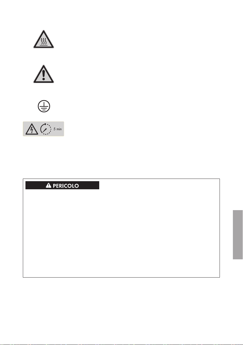
Pericolo di ustioni per contatto con superfici bollenti
Durante il funzionamento il prodotto può surriscaldarsi: evitare pertanto il
contatto in questa fase. Evitare pertanto il contatto durante il funzionamento. Prima di qualsiasi operazione, lasciar raffreddare a sufficienza il
prodotto.
Avviso
Questo simbolo ammonisce contro pericoli generali. In questo caso segnala che l’inverter deve essere ulteriormente messo a terra se a livello locale è richiesta una seconda messa a terra o un collegamento equipotenziale.
Conduttore di protezione
Questo simbolo indica il punto di collegamento di un conduttore di protezione.
Pericolo di morte per alta tensione nell’inverter: rispettare il tempo
di attesa, pari a 5 minuti.
Nei componenti sotto tensione all’interno dell’inverter sono presenti tensioni elevate che possono causare folgorazioni potenzialmente letali.
Prima di eseguire qualsiasi intervento sull’inverter, disinserire sempre la tensione.
3 Avvertenze di sicurezza
3 Avvertenze di sicurezza
Pericolo di morte per folgorazione a causa dei cavi CC sotto tensione sulla batteria
I cavi CC collegati alla batteria sono sotto tensione. Il contatto con conduttori CC o componenti
sotto tensione causa folgorazioni potenzialmente letali.
• Non toccare le estremità di cavi a vista.
• Non toccare i conduttori CC.
• Non toccare nessun componente sotto tensione.
• Affidare il montaggio, l’installazione e la messa in servizio dell’inverter e della batteria
esclusivamente a tecnici specializzati provvisti di apposita qualifica.
• Osservare tutte le avvertenze di sicurezza del produttore della batteria.
• Prima di eseguire qualsiasi operazione su inverter e batteria, disinserire sempre la tensione
come descritto nel presente documento.
• In caso di errore, incaricare esclusivamente un tecnico specializzato della sua risoluzione.
Guida rapida 19SBS25-1VL-10-IS-xx-14
ITALIANO
Page 20
4 Installazione
Pericolo di lesioni dovuto a correnti di cortocircuito
Le correnti di cortocircuito della batteria possono generare calore e archi voltaici. Ciò può
causare ustioni o lesioni agli occhi a causa dei lampi di luce.
• Togliere orologi, anelli e altri oggetti metallici.
• Utilizzare attrezzi isolati.
• Non appoggiare attrezzi o componenti metallici sulla batteria.
Danneggiamento della batteria dovuto a impostazioni errate
I parametri impostati per la batteria influiscono sul comportamento di carica di dell’inverter.
L’impostazione errata di parametri relativi a tipo di batteria, tensione nominale e capacità può
danneggiare la batteria.
• Al momento della configurazione, impostare il tipo di batteria e i valori corretti di tensione
nominale e capacità della batteria.
• Accertarsi che siano impostati i valori consigliati dal produttore della batteria (per i dati
tecnici della batteria v. la documentazione del produttore della batteria).
Pericolo di ustioni per contatto con parti surriscaldate dell’involucro
Durante il funzionamento alcune parti dell’involucro possono riscaldarsi.
• Montare l’inverter in modo da escludere ogni possibile contatto involontario quando lo
stesso è in funzione.
SMA Solar Technology AG
ITALIANO
Danneggiamento dell’inverter in seguito all’uso di detergenti
• Se l’inverter è sporco, pulire l’involucro, il coperchio dell’involucro, la targhetta di
identificazione e i LED esclusivamente con acqua pulita e un panno.
4 Installazione
Eseguire le operazioni rappresentate graficamente nel presente documento nella sequenza
indicata e rispettare tutte le note.
Le istruzioni per l’installazione dettagliate per l’installazione e la messa in
servizio, nonché le istruzioni per l’uso per la configurazione e l’eliminazione dei
guasti sono disponibili sul sito www.SMA-Solar.com.
Guida rapidaSBS25-1VL-10-IS-xx-1420
Page 21
SMA Solar Technology AG
5 Dichiarazione di conformità
5 Dichiarazione di conformità
Dichiarazione di conformità CE (valida fino al 19/04/2016)
Ai sensi delle direttive UE
• Compatibilità elettromagnetica 2004/108/CE (CEM)
• Bassa tensione 2006/95/CE (BT)
• Apparecchiature radio e terminali di telecomunicazione 1999/05/CE
(R&TTE)
SMA Solar Technology AG dichiara che gli inverter descritti all’interno del presente documento
sono conformi ai requisiti fondamentali e alle altre disposizioni rilevanti delle direttive sopra citate.
La dichiarazione di conformità CE completa è disponibile sul sito www.SMA-Solar.com.
Dichiarazione di conformità UE (valida dal 20/04/2016)
Ai sensi delle direttive UE
• Compatibilità elettromagnetica 2004/30/UE (29.3.2014 L 96/79-106)
(CEM)
• Bassa tensione 2014/35/UE (29.3.2014 L 96/357-374) (BT)
• Apparecchiature radio e terminali di telecomunicazione 1999/05/CE
(R&TTE)
SMA Solar Technology AG dichiara che gli inverter descritti all’interno del presente documento
sono conformi ai requisiti fondamentali e alle altre disposizioni rilevanti delle direttive sopra citate.
La dichiarazione di conformità UE completa è disponibile sul sito www.SMA-Solar.com.
Guida rapida 21SBS25-1VL-10-IS-xx-14
ITALIANO
Page 22
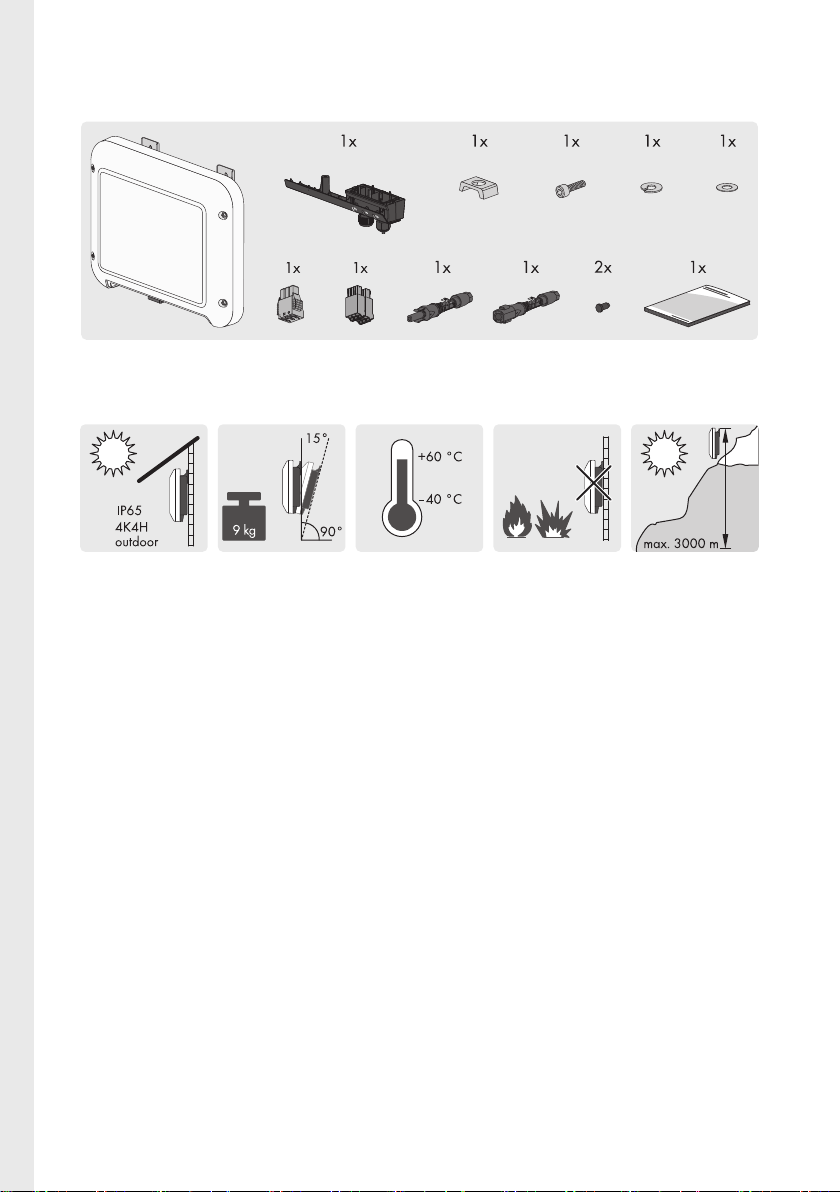
Scope of Delivery| Lieferumfang| Contenido de la entrega| Contenu
de la livraison| Contenuto della fornitura
Mounting location| Montageort| Lugar de montaje| Lieu de
montage| Luogo di montaggio
SBS25-1VL-10-IS-xx-1422
Page 23
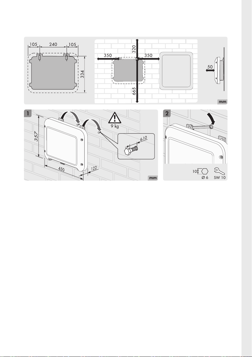
Mounting the Inverter| Wechselrichter montieren| Montaje del
inversor| Montage de l’onduleur| Montaggio dell’inverter
23SBS25-1VL-10-IS-xx-14
Page 24
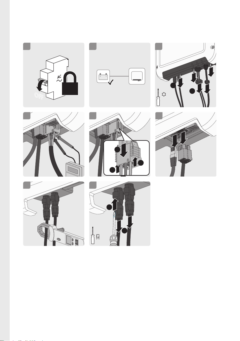
Disconnecting the Inverter from Voltage Sources| Wechselrichter
OFF
1
4
7
0.0A
3
1
2
3.5 Nm
TX 20
2
BATTERY
OFF
4
1
2
8
3 mm
6
L
N
4
<30V
L
N
L
N
1
1
2
5
spannungsfrei schalten| Desconexión del inversor de la tensión| Mise
hors tension de l’onduleur| Disinserzione dell’inverter
SBS25-1VL-10-IS-xx-1424
Page 25
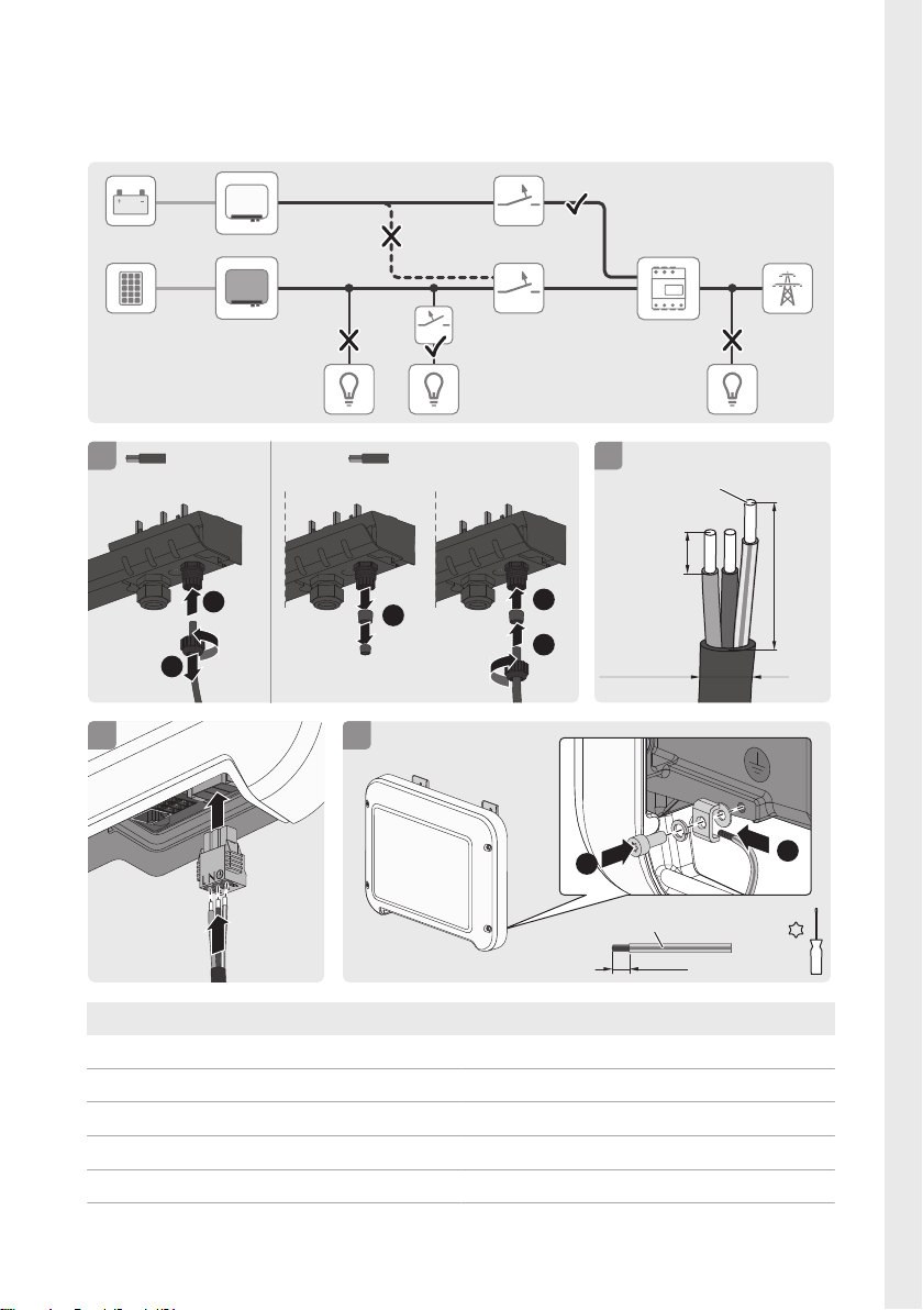
Connect the utility grid| Öffentlichen Stromnetz anschließen| Conexión
5 to 7 mmØ to 13 mmØ 8
2
1
L
N
1
3
PE
5 to 13 mm
15 mm
N
L
1.5 to 4 mm
2
70 mm
2
1
1
2
1
3
1
4
6 Nm
TX 25
2
1
1.5 to 10 mm
2
12 mm
Optional
de la red pública| Raccordement du réseau électrique public|
Collegamento alla rete pubblica
AC SBS2.5-1VL-10
P
AC (@ 230 V, 50 Hz)
S
AC (@ cos φ = 1)
V
AC, r
V
AC, range
I
AC, r (@ 220 V)
2500 W
2500 VA
220V / 230V / 240V
180 V to 280 V
11A
25SBS25-1VL-10-IS-xx-14
Page 26
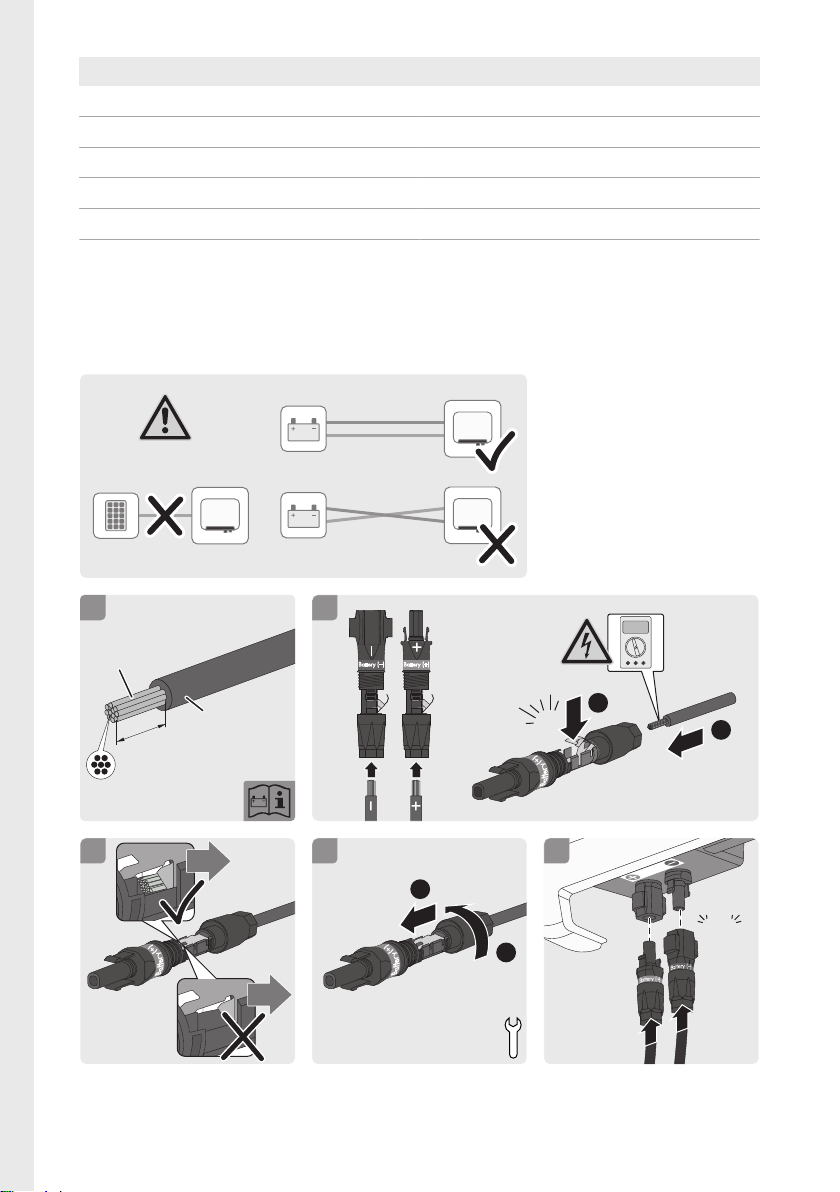
AC SBS2.5-1VL-10
2.5 to 6 mm
2
Ø 5 to 8 mm
≥ 7
PV1-F/UL-ZKLA/
USE2
U > 1000 V
15 mm
1
+
(+)
B
a
tt
e
r
y
+
4
322
Battery (−) Battery (+)
click
+
2
<30V
1
+
(+)
B
a
tt
e
r
y
BATTERY
+
_
OFF
+
_
+
_
+
_
OFF
PV
BATTERY
5
Battery
+
click
+
4
2
1
(+)
B
a
tt
e
r
y
2 Nm
+
I
AC, r (@ 230 V)
I
AC, r (@ 240 V)
I
AC,max
f
AC
cos φ
0.8 overexcited to 1 to 0.8 underexcited
11 A
10.5 A
11A
50 Hz / 60 Hz
Connecting the power cable of the battery| Batterieleistungskabel
anschließen| Conexión del cable de alimentación de la batería|
Raccordement des câbles de puissance de la batterie| Collegamento
del cavo di potenza della batteria
SBS25-1VL-10-IS-xx-1426
Page 27
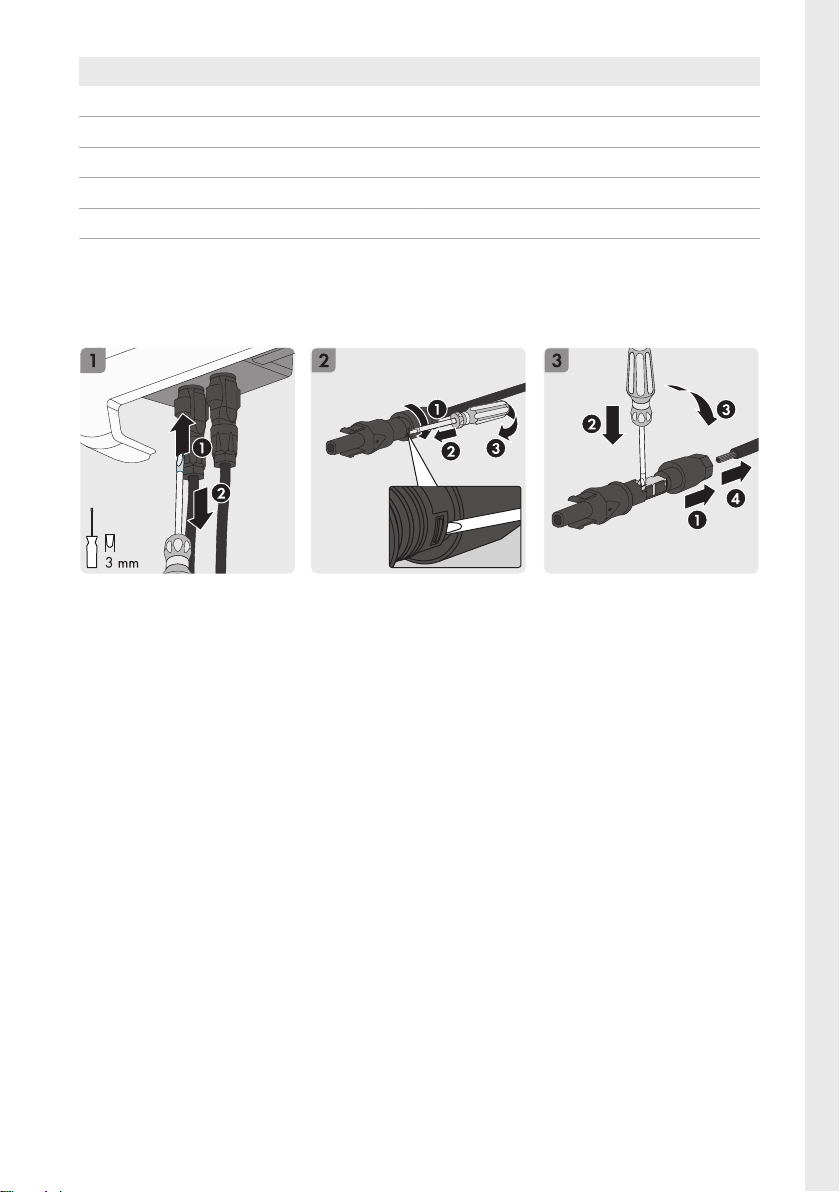
DC SBS2.5-1VL-10
P
DC, max (@ cos φ = 1)
V
DC, max
V
DC, range
I
DC, max
I
SC BAT
2650W
500V
100V to 500V
10A
18A
Disassembling the DC Connectors| DC-Steckverbinder demontieren|
Desmontaje de los conectadores de enchufe de CC| Démontage des
connecteursDC| Smontaggio dei terminali CC
27SBS25-1VL-10-IS-xx-14
Page 28
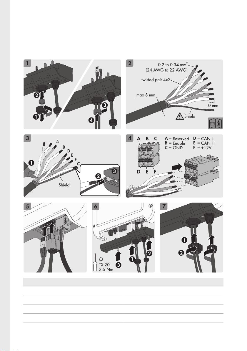
Connecting the data cable of the battery and network|
Batteriekommunikationskabel und Netzwerk anschließen| Conexión de
cable de comunicación de la batería y de la red| Raccordement des
câbles de communication et connexion au réseau| Collegamento del
cavo di comunicazione della batteria e della rete
U
out, nom
U
out
P
out, max
Enable
nom
SBS2.5-1VL-10
12V
11V to 14V
5W
11V
SBS25-1VL-10-IS-xx-1428
Page 29
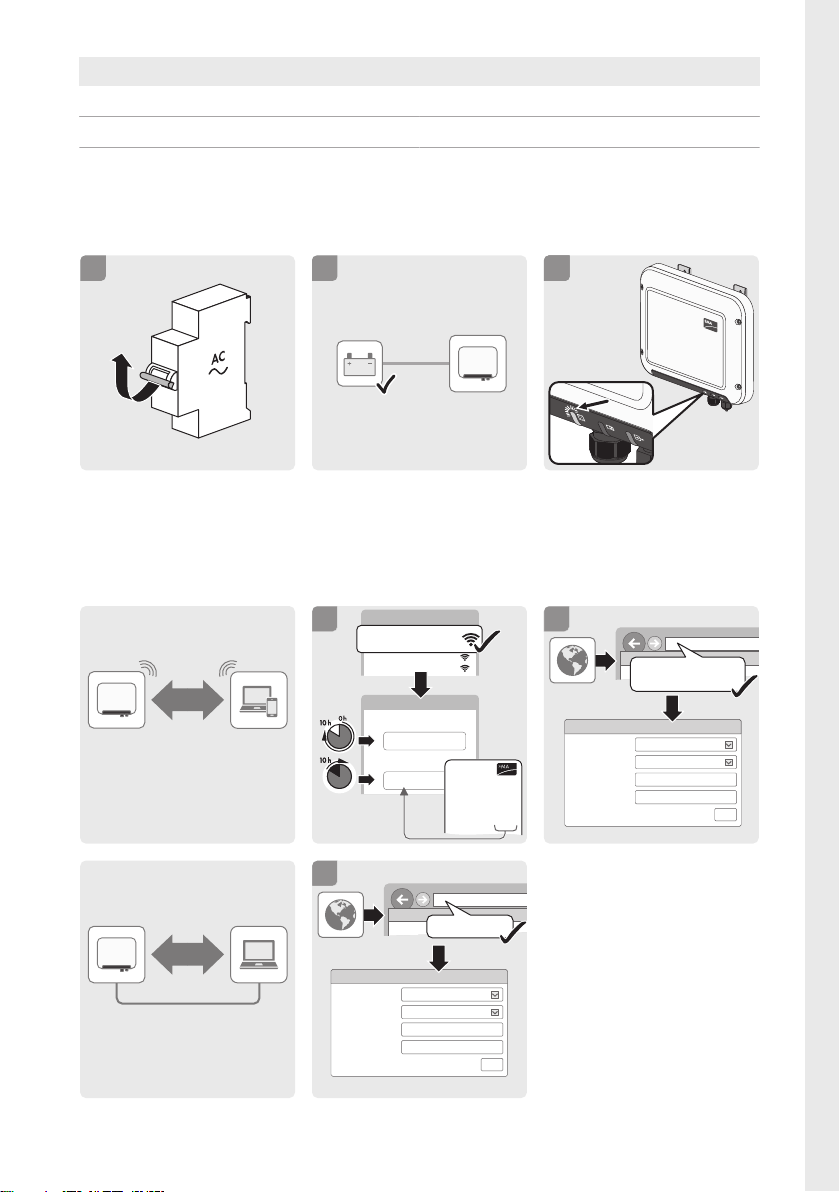
SBS2.5-1VL-10
SUNNY BOY STORAGE
OK
3
3
2
ON
1
BATTERY
ON
File Edit View Favorites Tools Help
2
Login Sunny Boy Storage 2.5
Language
User group
New password
English
Repeat password
Login
File Edit View Favorites Tools Help
1
Login Sunny Boy Storage 2.5
Language
User group
New password
English
Repeat password
Login
WLAN password
SMAxxxxxxxx
SUNNY BOY STORAGE
SBS2.5VL-10
XXXXXXXXXX
WPA2-PSK: XXX
SMA Solar Technology AG
Sonnenallee 1
34266 Niestetal
Germany
www.SMA.de
Model
Serial No.
1
Network 2
Network 1
SMAxxxxxxxx
WLAN
...
SMA12345
XXX
WLAN
Ethernet
169.254.12.2
192.168.12.3
SMAxxxxxxxx.local
or
Enable 10.5V to 11.5V
CAN 5V
Commissioning the Inverter| Wechselrichter in Betrieb nehmen| Puesta
en marcha del inversor| Mise en service de l’onduleur| Messa in
servizio dell’inverter
Establishing a connection to the user interface| Verbindung zur
Benutzeroberfläche aufbauen| Conexión con la interfaz de usuario|
Connectez-vous à l’interface utilisateur.| Stabilire un collegamento
all’interfaccia utente
29SBS25-1VL-10-IS-xx-14
Page 30
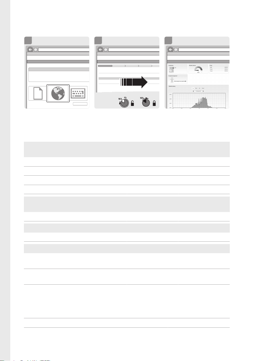
Configuring the Inverter| Wechselrichter konfigurieren| Configuración
File Edit View Favorites Tools Help
192.168.12.3
Sunny Boy XX
3
File Edit View Favorites Tools Help
192.168.12.3
Sunny Boy XX
Sunny Boy XX
Device name:
Serial number:
Firmware version:
Configuring the Inverter
Select a configuration option:
Skip configuration
1
File Edit View Favorites Tools Help
192.168.12.3
Sunny Boy XX
Network Configuration
4 532
Network Configuration Country standard
1
Time and date Grid management service Summary
Network configured
Network name Type of communication IP address of the inverter
Status
WLAN
Ethernet
Type of communication
2
SMA Grid
Guard-Code
...
del inversor| Configuration de l’onduleur| Configurazione dell’inverter
Default settings of the inverter| Werkseinstellungen des
Wechselrichters| Ajustes de fábrica del inversor| Réglages par défaut
de l’onduleur| Impostazioni di fabbrica dell’inverter
Voltage and frequency monitoring Treshold Max. disconnection
time
Lower limit AC voltage 195.5V 0.2000s
Upper limit AC voltage 264.5V 0.2000s
Lower limit AC frequency 47.50Hz 0.2000s
Upper limit AC frequency 51.50Hz 0.2000s
Loss of mains Active Max. disconnection
Active islanding detection No --s
Time before reconnection Active Grid monitoring time
Time to reconnection after a grid failure No --s
Grid quality Active Treshold
DC injection - max allowed value for the offset
of the AC current
Voltage rise protection - monitoring of 10min.
mean value, e.g. as per EN50160
System data| System-Daten| Datos del sistema| Données du
système| Dati del sistema
Topology transformerless
Overvoltage category in accordance with IEC 60664-1 II (DC), III (AC)
SBS25-1VL-10-IS-xx-1430
time
No 1A
Yes 253.0V
Page 31
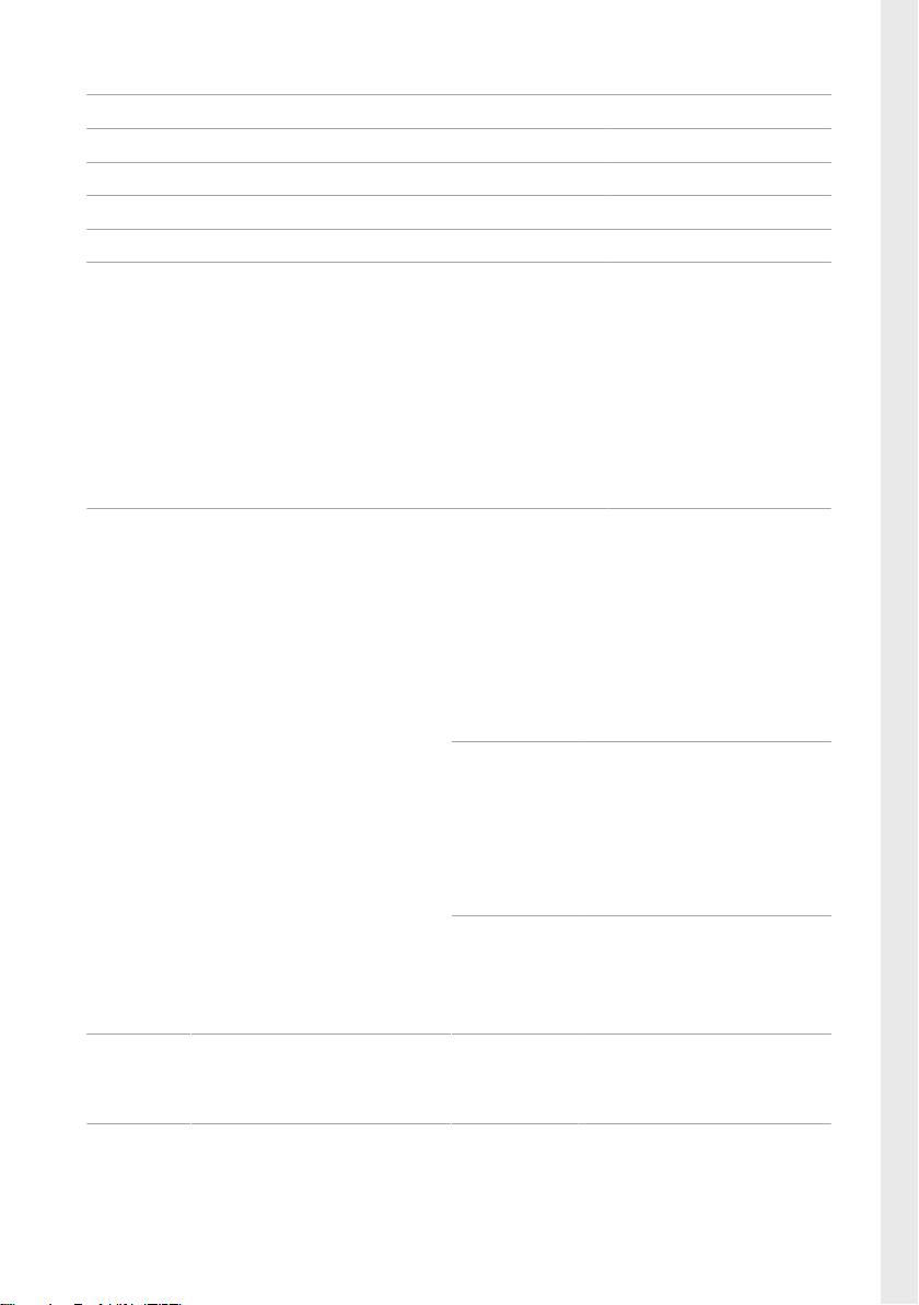
Protection class in accordance with IEC 61140 I
All-pole sensitive residual-current monitoring unit integrated
Maximum permissible value for relative humidity, non-condensing 100 %
Extended humidity range according to IEC 60721-3-4 0 % to 100 %
Pollution degree inside the enclosure 2
Pollution degree outside the enclosure 3
Local requirements NRS 97-2-1: This standard
requires a separate label
attached to the AC
distribution board, which
indicates the AC-side
disconnection of the inverter
in case of a grid failure (for
further details, see NRS
97-2-1, Sect. 4.2.7.1 and
4.2.7.2)
Contact| Kontakt| Contacto| Contact| Contatto
Danmark
Deutschland
Österreich
Schweiz
France SMA France S.A.S.
SMA Solar Technology AG
Niestetal
SMA Online Service Center:
www.SMA-Service.com
Sunny Boy, Sunny Mini Central,
SunnyTripower:
+495619522‑1499
Monitoring Systems (Kommunikationsprodukte):
+495619522‑2499
Fuel Save Controller (PV-DieselHybridsysteme):
+495619522-3199
Sunny Island, Sunny Boy Storage, Sunny Backup, Hydro Boy:
+495619522-399
Sunny Central:
+495619522-299
Lyon
+33 472 22 97 00
Belgien
Belgique
België
Luxemburg
Luxembourg
Nederland
Česko
Magyarország
România
Slovensko
Polska SMA Polska
Ελλάδα
Κύπρος
SMA Benelux BVBA/SPRL
Mechelen
+3215286 730
SMA Service Partner TERMS
a.s.
+420 387 6 85 111
+48122830666
SMA Hellas AE
Αθήνα
+30 210 9856666
31SBS25-1VL-10-IS-xx-14
Page 32
España
Portugal
Bulgaria
Italia
Romania
SMA Ibérica Tecnología Solar,
S.L.U.
Barcelona
+34935635099
SMA Italia S.r.l.
Milano
+39028934-7299
United Kingdom
SMA Solar UK Ltd.
Milton Keynes
+441908304899
France SMA France S.A.S.
Lyon
+33 472 22 97 00
United Arab
Emirates
SMA Middle East LLC
Abu Dhabi
+9712234 6177
SMA Solar (Thailand) Co., Ltd.
+6626706999
South Africa SMA Solar Technology South
Africa Pty Ltd.
Cape Town
08600SUNNY (08600 78669)
International: +27 (0)21 826
0600
Australia SMA Australia Pty Ltd.
Sydney
Toll free for Australia:
1800SMAAUS
(1800762287)
International: +61294914200
India SMA Solar India Pvt. Ltd.
Mumbai
+912261713888
대한민국 SMA Technology Korea Co.,
Ltd.
서울
+82-2-520-2666
Argentina
Brasil
Chile
SMA South America SPA
Santiago
+562 2820 2101
Perú
Other countries International SMA Service Line
Niestetal
Toll free worldwide:
00800SMASERVICE
(+8007627378423)
SBS25-1VL-10-IS-xx-1432
Page 33

Page 34
www.SMA-Solar.com
 Loading...