

Page 1
EN
Off-grid Inverter
SUNNY ISLAND 5048
Technical Description
SI5048-TEN093630 | TBE-SI5048 | Version 3.0
Page 2

Page 3

SMA Solar Technology AG Table of Contents
Table of Contents
1 Notes on this Manual. . . . . . . . . . . . . . . . . . . . . . . . . . . . . 11
1.1 Scope of Validity. . . . . . . . . . . . . . . . . . . . . . . . . . . . . . . . . . . . 11
1.2 Target Group . . . . . . . . . . . . . . . . . . . . . . . . . . . . . . . . . . . . . . 11
1.3 Additional Information . . . . . . . . . . . . . . . . . . . . . . . . . . . . . . . 11
1.4 Terminology . . . . . . . . . . . . . . . . . . . . . . . . . . . . . . . . . . . . . . . 11
1.5 Symbols Used . . . . . . . . . . . . . . . . . . . . . . . . . . . . . . . . . . . . . . 12
2 The Sunny Island 5048 . . . . . . . . . . . . . . . . . . . . . . . . . . . 13
2.1 Properties . . . . . . . . . . . . . . . . . . . . . . . . . . . . . . . . . . . . . . . . . 13
2.2 At a glance . . . . . . . . . . . . . . . . . . . . . . . . . . . . . . . . . . . . . . . . 17
2.3 Scope of delivery . . . . . . . . . . . . . . . . . . . . . . . . . . . . . . . . . . . 19
2.4 Identifying the Sunny Island . . . . . . . . . . . . . . . . . . . . . . . . . . . 20
3 Safety Precautions . . . . . . . . . . . . . . . . . . . . . . . . . . . . . . . 21
3.1 Important Notes Regarding Operation. . . . . . . . . . . . . . . . . . . 21
3.2 Potential Hazards . . . . . . . . . . . . . . . . . . . . . . . . . . . . . . . . . . . 22
4 Mounting the Device . . . . . . . . . . . . . . . . . . . . . . . . . . . . . 23
4.1 Selecting the Mounting Location. . . . . . . . . . . . . . . . . . . . . . . . 23
4.2 Mounting the Sunny Island with a Wall Mounting Bracket . . . 25
5 Opening and Closing. . . . . . . . . . . . . . . . . . . . . . . . . . . . . 27
5.1 Opening the Sunny Island . . . . . . . . . . . . . . . . . . . . . . . . . . . . 27
5.2 Closing the Sunny Island. . . . . . . . . . . . . . . . . . . . . . . . . . . . . . 28
6 Electrical Connection . . . . . . . . . . . . . . . . . . . . . . . . . . . . . 29
6.1 Connection to ground. . . . . . . . . . . . . . . . . . . . . . . . . . . . . . . . 30
6.2 DC connection . . . . . . . . . . . . . . . . . . . . . . . . . . . . . . . . . . . . . 31
6.2.1 Safety Precautions/Conditions . . . . . . . . . . . . . . . . . . . . . . . . . . . . . . . . . . . 32
6.2.2 Cable Sizing . . . . . . . . . . . . . . . . . . . . . . . . . . . . . . . . . . . . . . . . . . . . . . . . . 32
Technical Description SI5048-TEN093630 3
Page 4

Table of Contents SMA Solar Technology AG
6.2.3 Cable protection . . . . . . . . . . . . . . . . . . . . . . . . . . . . . . . . . . . . . . . . . . . . . . 33
6.2.4 Connection . . . . . . . . . . . . . . . . . . . . . . . . . . . . . . . . . . . . . . . . . . . . . . . . . . 33
6.3 AC Connection . . . . . . . . . . . . . . . . . . . . . . . . . . . . . . . . . . . . . 35
6.3.1 Cable protection . . . . . . . . . . . . . . . . . . . . . . . . . . . . . . . . . . . . . . . . . . . . . . 35
6.3.2 AC1 (Loads/Sunny Boys) . . . . . . . . . . . . . . . . . . . . . . . . . . . . . . . . . . . . . . . 35
6.3.3 AC2 (Generator/Grid) . . . . . . . . . . . . . . . . . . . . . . . . . . . . . . . . . . . . . . . . . 37
6.4 Additional Connections. . . . . . . . . . . . . . . . . . . . . . . . . . . . . . . 38
6.4.1 Battery temperature sensor . . . . . . . . . . . . . . . . . . . . . . . . . . . . . . . . . . . . . . 38
6.4.2 Battery Current Sensor . . . . . . . . . . . . . . . . . . . . . . . . . . . . . . . . . . . . . . . . . 40
6.4.3 Communication for Multi-device Connection . . . . . . . . . . . . . . . . . . . . . . . . 42
6.4.4 Multi-function Relays 1 and 2 . . . . . . . . . . . . . . . . . . . . . . . . . . . . . . . . . . . . 44
6.4.5 BatVtgOut Power Supply . . . . . . . . . . . . . . . . . . . . . . . . . . . . . . . . . . . . . . . 47
6.4.6 DigIn Digital Input . . . . . . . . . . . . . . . . . . . . . . . . . . . . . . . . . . . . . . . . . . . . . 48
6.5 Interface for External Communication. . . . . . . . . . . . . . . . . . . . 49
6.5.1 Connection of the Interface. . . . . . . . . . . . . . . . . . . . . . . . . . . . . . . . . . . . . . 49
7 Control Elements . . . . . . . . . . . . . . . . . . . . . . . . . . . . . . . . 51
7.1 Display Messages. . . . . . . . . . . . . . . . . . . . . . . . . . . . . . . . . . . 52
7.2 DC Circuit Breaker . . . . . . . . . . . . . . . . . . . . . . . . . . . . . . . . . . 52
7.3 Buttons . . . . . . . . . . . . . . . . . . . . . . . . . . . . . . . . . . . . . . . . . . . 53
7.4 Meaning of the Light Emitting Diodes (LEDs) . . . . . . . . . . . . . . 53
7.5 SD card. . . . . . . . . . . . . . . . . . . . . . . . . . . . . . . . . . . . . . . . . . . 53
8 Initial Commissioning. . . . . . . . . . . . . . . . . . . . . . . . . . . . . 54
8.1 Requirements. . . . . . . . . . . . . . . . . . . . . . . . . . . . . . . . . . . . . . . 54
8.2 Starting the Quick Configuration Guide (QCG). . . . . . . . . . . . 55
8.3 Commissioning the battery current sensor. . . . . . . . . . . . . . . . . 58
9 Activation and Deactivation . . . . . . . . . . . . . . . . . . . . . . . 60
9.1 Activation . . . . . . . . . . . . . . . . . . . . . . . . . . . . . . . . . . . . . . . . . 60
9.2 Stopping the Sunny Island (Standby) . . . . . . . . . . . . . . . . . . . . 61
9.3 Switch off . . . . . . . . . . . . . . . . . . . . . . . . . . . . . . . . . . . . . . . . . 62
4 SI5048-TEN093630 Technical Description
Page 5

SMA Solar Technology AG Table of Contents
9.4 Disconnect the device from voltage sources . . . . . . . . . . . . . . . 62
9.5 Reactivating the Device Following Automatic Shutdown . . . . . 63
10 Operation . . . . . . . . . . . . . . . . . . . . . . . . . . . . . . . . . . . . . . 64
10.1 Menu Structure . . . . . . . . . . . . . . . . . . . . . . . . . . . . . . . . . . . . . 65
10.2 Changing Parameters . . . . . . . . . . . . . . . . . . . . . . . . . . . . . . . . 68
10.3 Direct Access (to the parameters). . . . . . . . . . . . . . . . . . . . . . . 69
10.4 Compact Meters . . . . . . . . . . . . . . . . . . . . . . . . . . . . . . . . . . . . 69
10.5 Entering the installer password . . . . . . . . . . . . . . . . . . . . . . . . . 73
10.6 Display Messages (Overview) . . . . . . . . . . . . . . . . . . . . . . . . . 74
10.7 Parameter Display. . . . . . . . . . . . . . . . . . . . . . . . . . . . . . . . . . . 78
10.8 Display of Events. . . . . . . . . . . . . . . . . . . . . . . . . . . . . . . . . . . . 78
10.9 Display of Warnings and Failures. . . . . . . . . . . . . . . . . . . . . . . 79
11 Archiving Data on an SD Card . . . . . . . . . . . . . . . . . . . . . 80
11.1 Inserting the Card . . . . . . . . . . . . . . . . . . . . . . . . . . . . . . . . . . . 83
11.2 Removing the Card . . . . . . . . . . . . . . . . . . . . . . . . . . . . . . . . . . 84
11.3 Saving and Loading Parameters. . . . . . . . . . . . . . . . . . . . . . . . 84
11.4 Writing Log Data . . . . . . . . . . . . . . . . . . . . . . . . . . . . . . . . . . . 84
11.5 Status Messages . . . . . . . . . . . . . . . . . . . . . . . . . . . . . . . . . . . . 85
11.6 Firmware Update . . . . . . . . . . . . . . . . . . . . . . . . . . . . . . . . . . . 86
12 Additional Functions . . . . . . . . . . . . . . . . . . . . . . . . . . . . . 88
12.1 Load Shedding . . . . . . . . . . . . . . . . . . . . . . . . . . . . . . . . . . . . . 88
12.2 Sleep Mode . . . . . . . . . . . . . . . . . . . . . . . . . . . . . . . . . . . . . . . 89
12.3 Time-Controlled Operation . . . . . . . . . . . . . . . . . . . . . . . . . . . . 89
12.4 Overload and Short-Circuit Behavior . . . . . . . . . . . . . . . . . . . . 90
12.5 Device Faults and Autostart . . . . . . . . . . . . . . . . . . . . . . . . . . . 90
12.6 Automatic Frequency Adjustment (AFRA) . . . . . . . . . . . . . . . . . 90
12.7 Time-Controlled Standby. . . . . . . . . . . . . . . . . . . . . . . . . . . . . . 91
Technical Description SI5048-TEN093630 5
Page 6

Table of Contents SMA Solar Technology AG
12.8 Reaction in case of failures . . . . . . . . . . . . . . . . . . . . . . . . . . . . 91
13 Battery management . . . . . . . . . . . . . . . . . . . . . . . . . . . . . 92
13.1 Battery temperature . . . . . . . . . . . . . . . . . . . . . . . . . . . . . . . . . 92
13.2 Start Options. . . . . . . . . . . . . . . . . . . . . . . . . . . . . . . . . . . . . . . 93
13.3 State of Charge / SOC and SOH . . . . . . . . . . . . . . . . . . . . . . 93
13.4 Charge control . . . . . . . . . . . . . . . . . . . . . . . . . . . . . . . . . . . . . 94
13.4.1 Boost Charge . . . . . . . . . . . . . . . . . . . . . . . . . . . . . . . . . . . . . . . . . . . . . . . . 96
13.4.2 Full Charge . . . . . . . . . . . . . . . . . . . . . . . . . . . . . . . . . . . . . . . . . . . . . . . . . . 96
13.4.3 Equalization Charge . . . . . . . . . . . . . . . . . . . . . . . . . . . . . . . . . . . . . . . . . . . 97
13.4.4 Manual Equalization Charge . . . . . . . . . . . . . . . . . . . . . . . . . . . . . . . . . . . . 98
13.4.5 Silent Mode. . . . . . . . . . . . . . . . . . . . . . . . . . . . . . . . . . . . . . . . . . . . . . . . . . 98
13.5 Battery Preservation Mode . . . . . . . . . . . . . . . . . . . . . . . . . . . . 99
13.6 Battery Diagnostics . . . . . . . . . . . . . . . . . . . . . . . . . . . . . . . . . 100
13.7 Battery Lead Resistance . . . . . . . . . . . . . . . . . . . . . . . . . . . . . 101
14 Connecting External Sources . . . . . . . . . . . . . . . . . . . . . 102
14.1 Generator . . . . . . . . . . . . . . . . . . . . . . . . . . . . . . . . . . . . . . . . 102
14.1.1 Connection in Parallel . . . . . . . . . . . . . . . . . . . . . . . . . . . . . . . . . . . . . . . . . 103
14.1.2 Generator Start Options . . . . . . . . . . . . . . . . . . . . . . . . . . . . . . . . . . . . . . . 103
14.1.3 Generator Operation . . . . . . . . . . . . . . . . . . . . . . . . . . . . . . . . . . . . . . . . . 107
14.1.4 Manual Generator Operation . . . . . . . . . . . . . . . . . . . . . . . . . . . . . . . . . . 107
14.1.5 Automatic Generator Operation . . . . . . . . . . . . . . . . . . . . . . . . . . . . . . . . . 109
14.1.6 Limits and Power Adjustment. . . . . . . . . . . . . . . . . . . . . . . . . . . . . . . . . . . . 113
14.1.7 Run Times . . . . . . . . . . . . . . . . . . . . . . . . . . . . . . . . . . . . . . . . . . . . . . . . . . 114
14.1.8 Operation in Conjunction with PV Inverters. . . . . . . . . . . . . . . . . . . . . . . . . 115
14.1.9 Stopping the Generator . . . . . . . . . . . . . . . . . . . . . . . . . . . . . . . . . . . . . . . 116
14.1.10 Faults. . . . . . . . . . . . . . . . . . . . . . . . . . . . . . . . . . . . . . . . . . . . . . . . . . . . . . 116
14.2 Grid . . . . . . . . . . . . . . . . . . . . . . . . . . . . . . . . . . . . . . . . . . . . 117
14.2.1 Boundary Conditions . . . . . . . . . . . . . . . . . . . . . . . . . . . . . . . . . . . . . . . . . 118
14.2.2 Starting the Sunny Island. . . . . . . . . . . . . . . . . . . . . . . . . . . . . . . . . . . . . . . 118
14.2.3 Stand-Alone Grid Operation. . . . . . . . . . . . . . . . . . . . . . . . . . . . . . . . . . . . 118
6 SI5048-TEN093630 Technical Description
Page 7

SMA Solar Technology AG Table of Contents
14.2.4 Grid Reconnection . . . . . . . . . . . . . . . . . . . . . . . . . . . . . . . . . . . . . . . . . . . 118
14.2.5 Grid operation . . . . . . . . . . . . . . . . . . . . . . . . . . . . . . . . . . . . . . . . . . . . . . 119
14.2.6 Grid Failure . . . . . . . . . . . . . . . . . . . . . . . . . . . . . . . . . . . . . . . . . . . . . . . . . 120
14.2.7 Failures . . . . . . . . . . . . . . . . . . . . . . . . . . . . . . . . . . . . . . . . . . . . . . . . . . . . 120
14.2.8 Limits and Power Adjustment. . . . . . . . . . . . . . . . . . . . . . . . . . . . . . . . . . . . 121
14.2.9 Operation in Conjunction with PV Inverters. . . . . . . . . . . . . . . . . . . . . . . . . 121
14.3 Generator and Grid . . . . . . . . . . . . . . . . . . . . . . . . . . . . . . . . 121
15 Relays . . . . . . . . . . . . . . . . . . . . . . . . . . . . . . . . . . . . . . . . 123
16 Multicluster Operation. . . . . . . . . . . . . . . . . . . . . . . . . . . 125
16.1 Communication between the Sunny Island. . . . . . . . . . . . . . . 125
16.2 Initial Commissioning of the Multicluster System. . . . . . . . . . . 128
16.3 Switching a Multicluster System On and Off . . . . . . . . . . . . . 129
16.3.1 Activation / Startup. . . . . . . . . . . . . . . . . . . . . . . . . . . . . . . . . . . . . . . . . . . 129
16.3.2 Stopping and Deactivating . . . . . . . . . . . . . . . . . . . . . . . . . . . . . . . . . . . . . 129
16.4 Generator Operation . . . . . . . . . . . . . . . . . . . . . . . . . . . . . . . 130
16.5 Behavior with Different Charge States . . . . . . . . . . . . . . . . . . 130
16.6 Communication Test . . . . . . . . . . . . . . . . . . . . . . . . . . . . . . . . 131
16.7 Automatic Frequency Adjustment (AFRA) . . . . . . . . . . . . . . . . 131
16.8 Firmware Update . . . . . . . . . . . . . . . . . . . . . . . . . . . . . . . . . . 131
16.9 Fault Handling in a Multicluster System . . . . . . . . . . . . . . . . . 132
16.10 Grid operation . . . . . . . . . . . . . . . . . . . . . . . . . . . . . . . . . . . . 132
16.11 Generator Emergency Operation. . . . . . . . . . . . . . . . . . . . . . 132
17 PV Inverters in the Stand-Alone Grid System . . . . . . . . 133
17.1 Setting Stand-Alone Grid Operation. . . . . . . . . . . . . . . . . . . . 133
17.1.1 Setting using the rotary switch on SB 3000TL / 4000TL / 5000TL . . . . . . 134
17.1.2 Setting using the rotary switch on SB 2000HF / 2500HF / 3000HF
and STP 10000TL / 12000TL / 15000TL / 17000TL. . . . . . . . . . . . . . . . 134
17.1.3 Settings Via Communication or Sowftare . . . . . . . . . . . . . . . . . . . . . . . . . . 134
17.2 Use of SB 3000TL / 4000TL / 5000TL in 60 Hz Grids. . . . . 135
Technical Description SI5048-TEN093630 7
Page 8

Table of Contents SMA Solar Technology AG
18 Maintenance and Care . . . . . . . . . . . . . . . . . . . . . . . . . . 136
18.1 Enclosure. . . . . . . . . . . . . . . . . . . . . . . . . . . . . . . . . . . . . . . . . 136
18.2 Cleaning the Fans . . . . . . . . . . . . . . . . . . . . . . . . . . . . . . . . . . 136
18.3 Display . . . . . . . . . . . . . . . . . . . . . . . . . . . . . . . . . . . . . . . . . . 136
18.4 Function. . . . . . . . . . . . . . . . . . . . . . . . . . . . . . . . . . . . . . . . . . 136
18.5 Battery. . . . . . . . . . . . . . . . . . . . . . . . . . . . . . . . . . . . . . . . . . . 136
18.6 Disposal . . . . . . . . . . . . . . . . . . . . . . . . . . . . . . . . . . . . . . . . . 136
19 Parameter lists . . . . . . . . . . . . . . . . . . . . . . . . . . . . . . . . . 137
19.1 Display values. . . . . . . . . . . . . . . . . . . . . . . . . . . . . . . . . . . . . 137
19.1.1 Inverter Meters (110#) . . . . . . . . . . . . . . . . . . . . . . . . . . . . . . . . . . . . . . . . 137
19.1.2 Battery Meters (120#) . . . . . . . . . . . . . . . . . . . . . . . . . . . . . . . . . . . . . . . . 141
19.1.3 External Meters (130#) . . . . . . . . . . . . . . . . . . . . . . . . . . . . . . . . . . . . . . . 142
19.1.4 Charge Controller (140#) . . . . . . . . . . . . . . . . . . . . . . . . . . . . . . . . . . . . . 145
19.2 Adjustable parameters . . . . . . . . . . . . . . . . . . . . . . . . . . . . . . 147
19.2.1 Inverter Settings (210#) . . . . . . . . . . . . . . . . . . . . . . . . . . . . . . . . . . . . . . . 147
19.2.2 Battery Settings (220#). . . . . . . . . . . . . . . . . . . . . . . . . . . . . . . . . . . . . . . . 148
19.2.3 External Settings (230#). . . . . . . . . . . . . . . . . . . . . . . . . . . . . . . . . . . . . . . 152
19.2.4 Relay Settings (240#). . . . . . . . . . . . . . . . . . . . . . . . . . . . . . . . . . . . . . . . . 160
19.2.5 System Settings (250#). . . . . . . . . . . . . . . . . . . . . . . . . . . . . . . . . . . . . . . . 170
19.2.6 Password Setting (280#) . . . . . . . . . . . . . . . . . . . . . . . . . . . . . . . . . . . . . . 171
19.3 Diagnosis (300#) . . . . . . . . . . . . . . . . . . . . . . . . . . . . . . . . . . 172
19.3.1 Inverter Diagnosis (310#). . . . . . . . . . . . . . . . . . . . . . . . . . . . . . . . . . . . . . 172
19.3.2 Battery Diagnosis (320#) . . . . . . . . . . . . . . . . . . . . . . . . . . . . . . . . . . . . . . 177
19.3.3 External Diagnosis (330#) . . . . . . . . . . . . . . . . . . . . . . . . . . . . . . . . . . . . . 179
19.4 Events, Warnings and Failures (History) . . . . . . . . . . . . . . . . . 180
19.4.1 Failure / Event (400#) . . . . . . . . . . . . . . . . . . . . . . . . . . . . . . . . . . . . . . . . 180
19.5 Functions in Operation . . . . . . . . . . . . . . . . . . . . . . . . . . . . . . 180
19.5.1 Operation (500#). . . . . . . . . . . . . . . . . . . . . . . . . . . . . . . . . . . . . . . . . . . . 180
19.6 Direct Access to the parameters . . . . . . . . . . . . . . . . . . . . . . . 183
19.6.1 Direct Access (600#) . . . . . . . . . . . . . . . . . . . . . . . . . . . . . . . . . . . . . . . . . 183
8 SI5048-TEN093630 Technical Description
Page 9

SMA Solar Technology AG Table of Contents
20 Troubleshooting . . . . . . . . . . . . . . . . . . . . . . . . . . . . . . . . 184
20.1 Error Confirmation. . . . . . . . . . . . . . . . . . . . . . . . . . . . . . . . . . 184
20.2 Autostart Handling . . . . . . . . . . . . . . . . . . . . . . . . . . . . . . . . . 184
20.3 Master Slave Handling. . . . . . . . . . . . . . . . . . . . . . . . . . . . . . 185
20.4 Handling Pending Errors During the Booting Procedure. . . . . 185
20.5 Display of Errors and Events . . . . . . . . . . . . . . . . . . . . . . . . . . 186
20.6 Events . . . . . . . . . . . . . . . . . . . . . . . . . . . . . . . . . . . . . . . . . . . 186
20.6.1 Category INV . . . . . . . . . . . . . . . . . . . . . . . . . . . . . . . . . . . . . . . . . . . . . . . 186
20.6.2 Category BAT . . . . . . . . . . . . . . . . . . . . . . . . . . . . . . . . . . . . . . . . . . . . . . . 187
20.6.3 Category GEN . . . . . . . . . . . . . . . . . . . . . . . . . . . . . . . . . . . . . . . . . . . . . . 187
20.6.4 Category GRD . . . . . . . . . . . . . . . . . . . . . . . . . . . . . . . . . . . . . . . . . . . . . . 187
20.6.5 Category REL . . . . . . . . . . . . . . . . . . . . . . . . . . . . . . . . . . . . . . . . . . . . . . . 188
20.6.6 Category SYS . . . . . . . . . . . . . . . . . . . . . . . . . . . . . . . . . . . . . . . . . . . . . . . 189
20.7 Error Categories . . . . . . . . . . . . . . . . . . . . . . . . . . . . . . . . . . . 190
20.8 Warnings and Fault Indications . . . . . . . . . . . . . . . . . . . . . . . 191
20.8.1 Category INV . . . . . . . . . . . . . . . . . . . . . . . . . . . . . . . . . . . . . . . . . . . . . . . 191
20.8.2 Category BAT . . . . . . . . . . . . . . . . . . . . . . . . . . . . . . . . . . . . . . . . . . . . . . . 192
20.8.3 Category EXT . . . . . . . . . . . . . . . . . . . . . . . . . . . . . . . . . . . . . . . . . . . . . . . 192
20.8.4 Category GEN . . . . . . . . . . . . . . . . . . . . . . . . . . . . . . . . . . . . . . . . . . . . . . 194
20.8.5 Category GRD . . . . . . . . . . . . . . . . . . . . . . . . . . . . . . . . . . . . . . . . . . . . . . 194
20.8.6 Category RLY . . . . . . . . . . . . . . . . . . . . . . . . . . . . . . . . . . . . . . . . . . . . . . . 194
20.8.7 Category SYS . . . . . . . . . . . . . . . . . . . . . . . . . . . . . . . . . . . . . . . . . . . . . . . 195
20.8.8 AUX Category. . . . . . . . . . . . . . . . . . . . . . . . . . . . . . . . . . . . . . . . . . . . . . . 196
20.9 Troubleshooting . . . . . . . . . . . . . . . . . . . . . . . . . . . . . . . . . . . 198
20.10 Procedure During Emergency Charge Mode . . . . . . . . . . . . . 201
21 Accessories . . . . . . . . . . . . . . . . . . . . . . . . . . . . . . . . . . . . 204
22 Technical Data . . . . . . . . . . . . . . . . . . . . . . . . . . . . . . . . . 205
23 Contact . . . . . . . . . . . . . . . . . . . . . . . . . . . . . . . . . . . . . . . 208
Technical Description SI5048-TEN093630 9
Page 10

Table of Contents SMA Solar Technology AG
10 SI5048-TEN093630 Technical Description
Page 11

SMA Solar Technology AG Notes on this Manual
1 Notes on this Manual
This manual describes the functionality, mounting, electrical connections and operation of the
Sunny Island 5048. Store this manual where it will be accessible at all times.
1.1 Scope of Validity
This manual is valid for the Sunny Island 5048 (SI 5048), firmware versions 5.0 and later.
1.2 Target Group
This manual is exclusively for qualified personnel. The tasks described in this manual may only be
performed by qualified personnel.
1.3 Additional Information
You will find further information on special topics such as selecting and using PV inverters in standalone grid systems in the download area at www.SMA.de/en.
1.4 Terminology
The syntax specified here for menus and parameters applies throughout the entire manual:
Menu: Menu number, hash and menu name (150# Compact Meters)
Parameter: Menu number, dot, parameter number and parameter name (150.01 GdRmgTm)
Technical Description SI5048-TEN093630 11
Page 12
Notes on this Manual SMA Solar Technology AG
1.5 Symbols Used
DANGER!
”DANGER” indicates a hazardous situation which, if not avoided, will result in certain
death or serious injury!
WARNING!
”WARNING” indicates a hazardous situation which, if not avoided, could result in death
or serious injury!
CAUTION!
”CAUTION” indicates a hazardous situation which, if not avoided, could result in minor or
moderate injury!
NOTICE!
”NOTICE” indicates a situation that can result in property damage if not avoided!
Information
Information provides useful hints for the optimum installation and operation of your
product.
12 SI5048-TEN093630 Technical Description
Page 13

SMA Solar Technology AG The Sunny Island 5048
2 The Sunny Island 5048
2.1 Properties
The Sunny Island 5048 is a bi-directional battery inverter (battery inverter and charger) for off-grid
systems. The Sunny Island supplies loads on the stand-alone grid side and charges battery banks with
the energy from grid-feeding units connected on the AC side.
The comfortable support of AC and DC coupling as well as the expandability of the systems formed
with the Sunny Island guarantee highest flexibility. In addition, innovative technology allows the
Sunny Island to achieve a maximum efficiency of more than 95 %. Optimized for partial load
operation it impresses with a low open-circuit and standby consumption. Due to the high overload
capabilities and the integrated output management, there is no need to oversize the Sunny Island.
The parallel operation of up to 4 devices on a single phase of a battery or of three devices on a
three-phase system enables the Sunny Island to be used to set up stand-alone power supply systems
with outputs of 3 to 26 kW. In doing this it is capable, with the aid of its sophisticated generator
management, of controlling a diesel generator connected to it in a particularly sparing and fuel-saving
manner. It can also be integrated into the public grid. The Sunny Island can also deactivate loads
automatically if the battery does not provide sufficient electrical energy.
The stand-alone grid's critical component, the battery, is monitored diligently and utilized optimally.
The intelligent battery management precisely records the battery's charge level. This makes an
improved utilization of the battery capacity possible, which also means that smaller and thus more
cost-effective batteries can be used without affecting performance.
In order to prevent premature aging caused by incorrect charging and frequent deep discharge, the
Sunny Island has an intelligent charge control and reliable deep discharge protection. Because of
these functions the battery service life can be largely extended in comparison with simpler devices.
Despite its complex functioning, the Sunny Island is easy to configure. All the settings required for
operation can be quickly and easily programmed in a few steps using the "Quick Configuration
Guide". By employing the concept of central operation referred to as "Single Point of Operation",
the system/cluster parameters are only set on the master device, and all other devices automatically
adopt the configuration. The easy-to-understand menu navigation allows quick access to all important
data, even while the system is running. An SD card provides uncomplicated system control, and thus
makes any service work easier.
Saving Data and Events
Always use the SD card to save data and events. In case of a failure SMA
Solar Technology can thus quickly help you.
Th e Su nny Isl and mo nit ors the set vol tag e an d frequ enc y li mit s on the grid and generator. If these limits
are not observed, it disconnects from the external source without interruption and changes to
stand-alone grid operation. The Sunny Island also has an integrated anti-islanding process in order to
prevent unintended islanding on the public grid. If this process is triggered, the system also completely
switches into stand-alone mode without interruption.
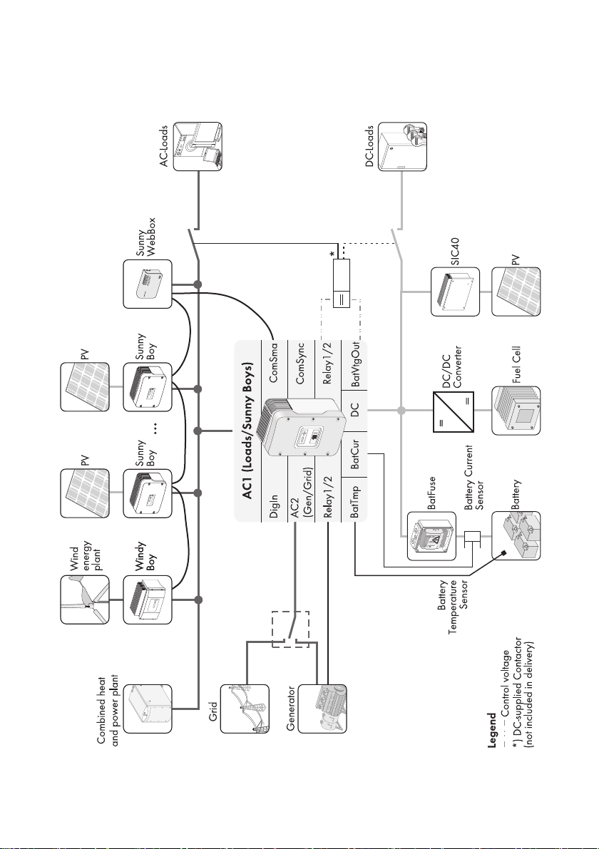
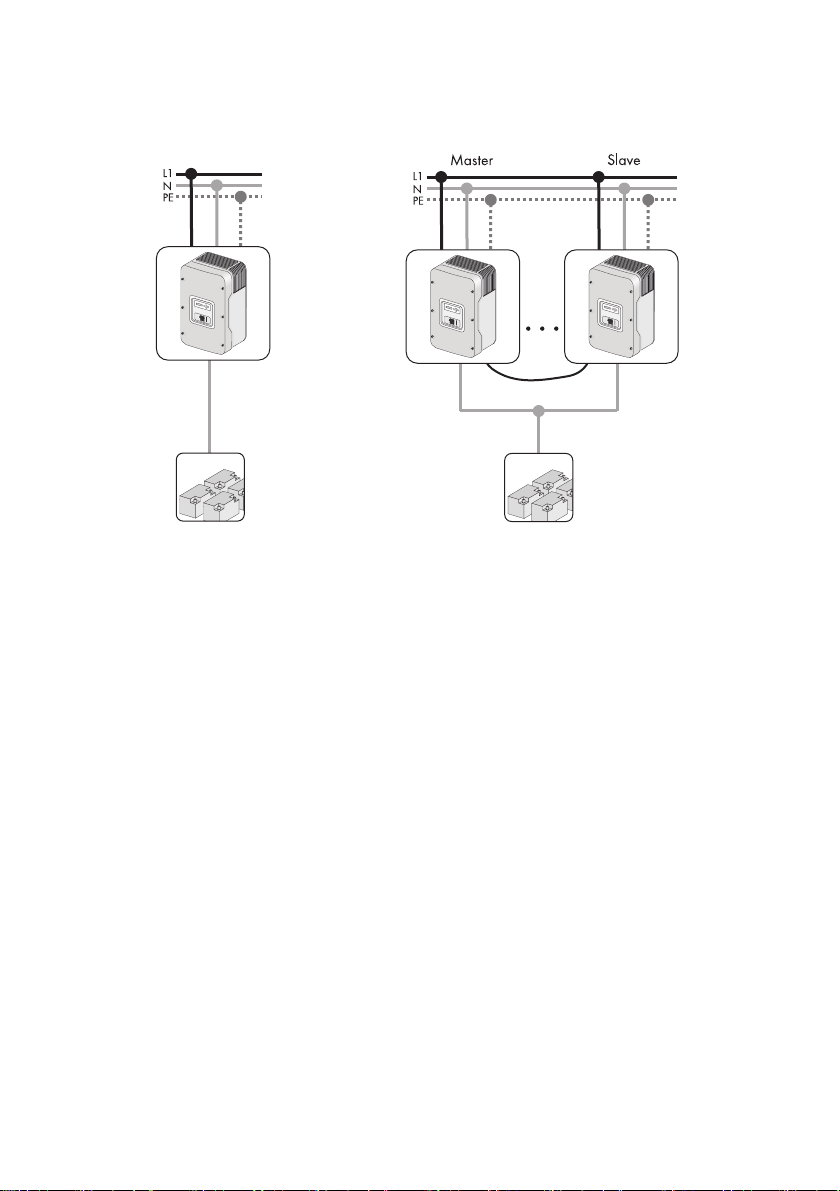
The Sunny Island can be integrated into different system constellations. The following graphics show
the components of a Sunny Island System and the different wirings (single-phase, single-phase
parallel and three-phase).
Technical Description SI5048-TEN093630 13
Page 14
The Sunny Island 5048 SMA Solar Technology AG
Components of a Sunny Island System
14 SI5048-TEN093630 Technical Description
Page 15
SMA Solar Technology AG The Sunny Island 5048
Single-phase and Single-phase parallel system:
Technical Description SI5048-TEN093630 15
Page 16
The Sunny Island 5048 SMA Solar Technology AG
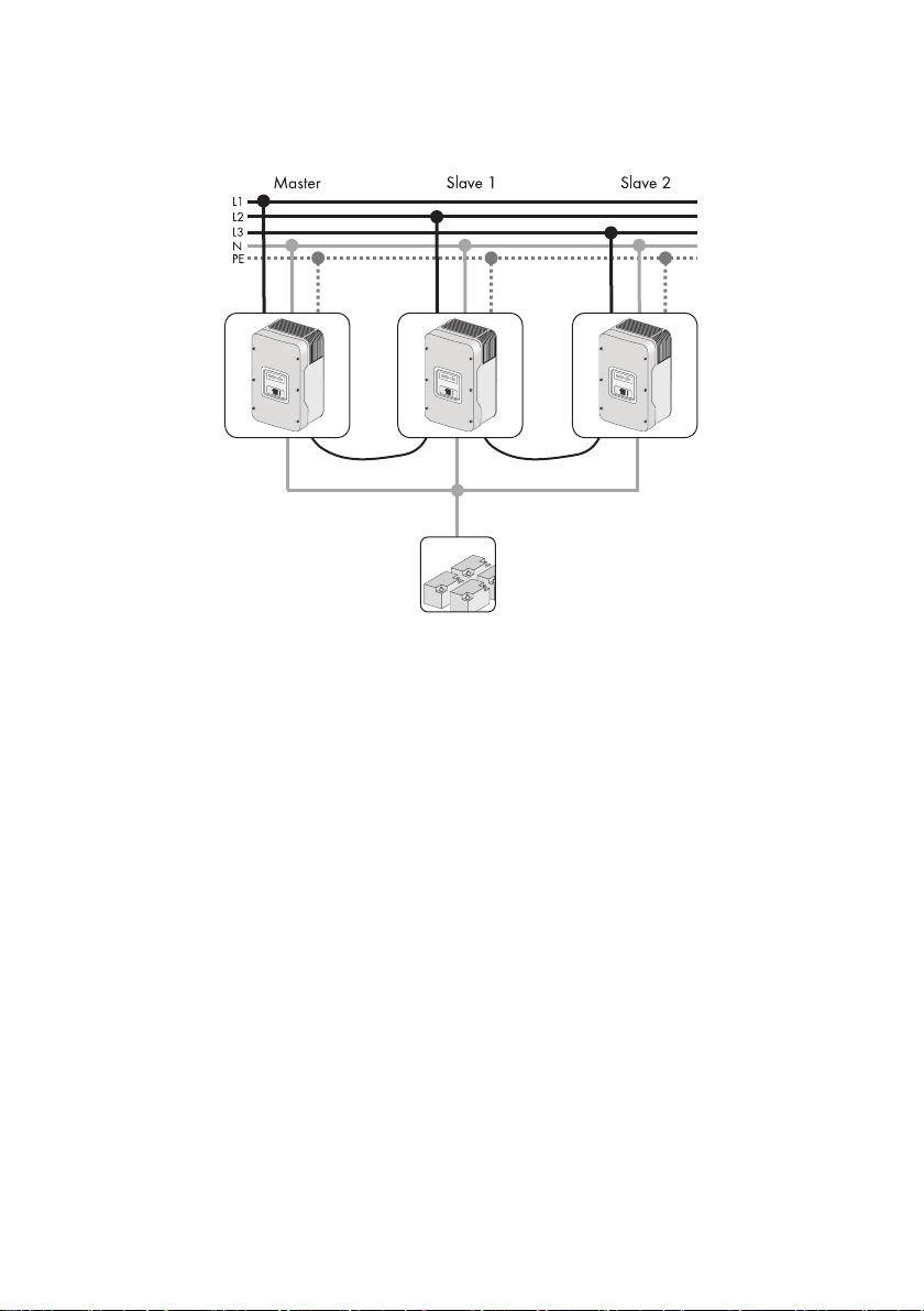
Three-phase system (cluster):
120
16 SI5048-TEN093630 Technical Description
Page 17
SMA Solar Technology AG The Sunny Island 5048
2.2 At a glance
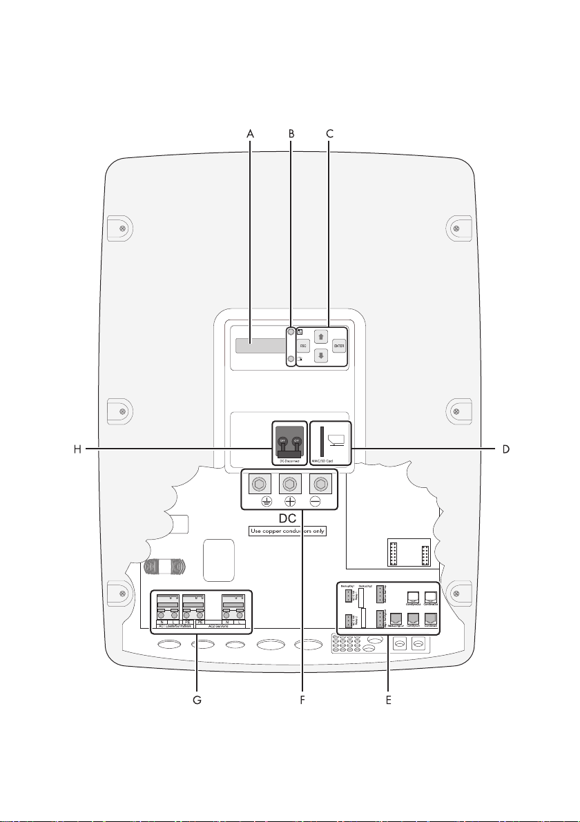
The following figure provides an overview of all control elements and connections of the Sunny Island:
Technical Description SI5048-TEN093630 17
Page 18
The Sunny Island 5048 SMA Solar Technology AG
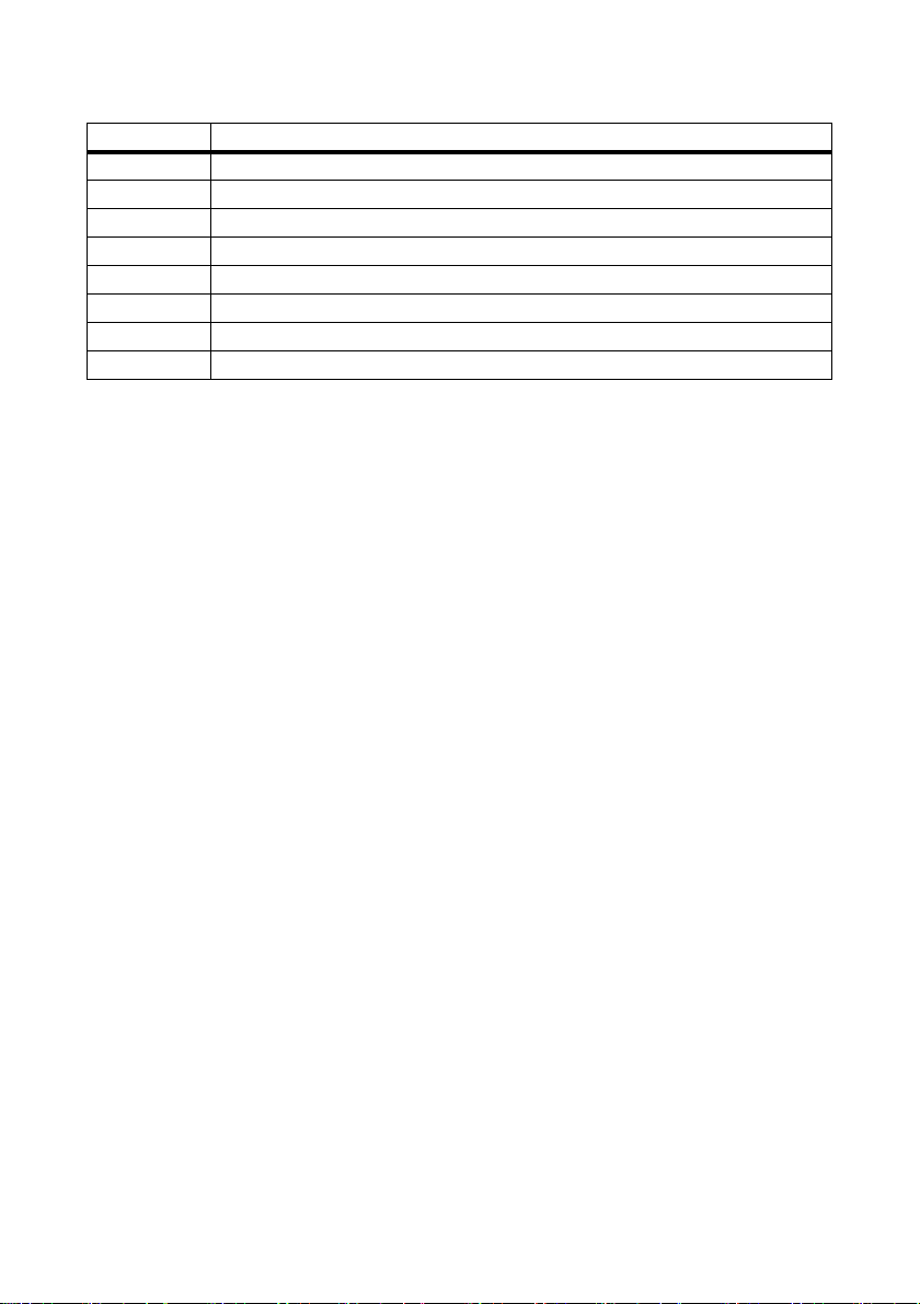
Position Description
ADisplay
B LEDs showing device operation
C Control buttons
D Slot for the SD card
E Connection area for additional connections
FDC connection area
GAC connection area
HDC circuit breaker
18 SI5048-TEN093630 Technical Description
Page 19
SMA Solar Technology AG The Sunny Island 5048
2.3 Scope of delivery
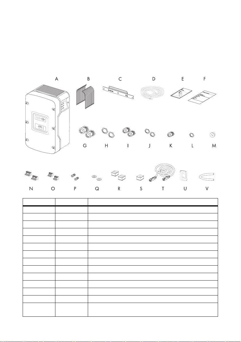
Check the delivery for completeness. Check the packaging and the Sunny Island for externally visible
damage.
Contact your supplier in case of damage to the packaging. Please contact your dealer if you find any
damage on the Sunny Insland or if there are parts missing in the delivery.
Position Quantity Description
A 1 Sunny Island
B2Air grills
C 1 Wall mounting bracket
D 1 Battery temperature sensor
E1Technical Description
F1Document set
G 2 M32 cable screw connection
H 2 Counter nut for M32 cable screw connection
I 2 M25 cable screw connection
J 2 Counter nut for M25 cable screw connection
K 2 M20 cable screw connection
L 2 Counter nut for M20 cable screw connection
M1 Blanking plugs
N 2 4-pole print terminal for connecting the battery temperature and
current sensors
Technical Description SI5048-TEN093630 19
Page 20
The Sunny Island 5048 SMA Solar Technology AG
Position Quantity Description
O 2 3-pole print terminal for the connection of relays 1 and 2
P 2 M6x10 mm hexagon socket screw to attach the Sunny Island to
the wall mounting bracket
Q 2 M6 contact washers to attach the Sunny Island to the wall
mounting bracket
R 2 rubber plugs for feed-through of 2 cables
S 1 rubber plugs for feed-through of one cable
T 1 RJ45 Cable
U1SD card
V1Silicone tube
2.4 Identifying the Sunny Island
Identify the Sunny Island by the serial number (Serial No.) and the device type (Type) on the type
plate. The type plate is on the right side of the enclosure.
20 SI5048-TEN093630 Technical Description
Page 21
SMA Solar Technology AG Safety Precautions
3 Safety Precautions
3.1 Important Notes Regarding Operation
Please follow all operating and safety instructions in this manual. If these instructions are ignored,
a significant danger of injury or death arises and damage to the device, system or plant may also
result. Carefully read the safety precautions before installing and commissioning the device. Store the
manual at an easily accessible location.
DANGER!
Electric shock due to high voltage in the Sunny Island. Death or serious injuries.
• All work on the Sunny Island must only be carried out by qualified personnel.
• Work on the Sunny Island should only be carried out as described in this manual.
• All listed safety instructions must be followed.
NOTICE!
Destruction of the Sunny Island due to parallel connection of different types of
tension.
• Always employ Sunny Islands of the same type within a system.
• Never operate with different tension types in parallel.
Connection Requirements
Be sure to observe all applicable regional standards and guidelines.
internal consumption
The operating consumption of the Sunny Island discharges the battery. In standby mode
this load is about 4W and in idle mode it is about 25 W. Observe this when you install the
Sunny Island, but do not use it immediately or do not use it for an extended period of time
within the year.
It may be necessary to set the Sunny Island to Stop mode (see section 9.3”Switch off”
(page62)) and disconnect it from the battery by means of the DC circuit breaker.
Altitude
The Sunny Island has been designed for use at elevations of up to 3000 m above sea level.
Please contact SMA Sol ar Technology befor e using the device at elevations above 3000 m.
A performance loss of 0.5 % per 100 m is to be expected starting at an elevation of
2000 m above sea level!
Technical Description SI5048-TEN093630 21
Page 22
Safety Precautions SMA Solar Technology AG
3.2 Potential Hazards
DANGER!
Electric shock due to high voltage and currents in the Sunny Island upon contact.
Death or serious injuries.
Complete protection against accidental contact is provided when the following points are
followed according to the handbook:
• The Sunny Island is mounted correctly.
• The Sunny Island is properly grounded.
• All connections are made correctly.
• The enclosure lid is securely closed.
DANGER!
Electric shock due to high voltages in the stand-alone grid. Death or serious
injuries.
The Sunny Island can start on its own.
• Before working on the stand-alone grid disconnect all AC and DC power sources.
DANGER!
Death hazard if the Sunny Island is used to supply energy to life-sustaining
medical devices.
This device was not developed to power life-sustaining medical devices.
• Never use the Sunny Island in systems in which a power outage might result in
personal injury.
NOTICE!
Destruction of the device due to incorrect installation.
The Sunny Island has protection rating IP30 (IP40 with an inserted SD card) and is
therefore only suited for installation in enclosed spaces.
• Never expose the Sunny Island to humidity, rain or direct sunlight.
22 SI5048-TEN093630 Technical Description
Page 23
SMA Solar Technology AG Mounting the Device
4 Mounting the Device
4.1 Selecting the Mounting Location
DANGER!
Danger of death if installed in improper locations. Death or serious burns.
Despite careful construction, a fire can occur with electrical devices.
• Do not mount the Sunny Island on flammable construction materials.
• Do not mount the Sunny Island near highly flammable materials.
• Do not mount the Sunny Island in potentially explosive areas.
CAUTION!
Risk of burns through contact with the hot enclosure during operation.
Burns to the body.
• Mount the inverter in such a way that the enclosure cannot be touched inadvertently.
CAUTION!
Risk of injury due to the Sunny Island falling during transport.
Physical injury (fractures or crushing) and damage to the Sunny Island.
• Consider the weight of the Sunny Island (63 kg).
Overheating of the inverter due to close proximity to other inverters in areas with
high ambient temperatures.
If several inverters have been installed in areas with high ambient temperatures, the
independent cooling of the individual inverters needs to be guaranteed.
If needed, increase the distance between individual inverters and make sure that there is
an adequate fresh air supply in order to ensure the optimal operation of the inverters.
Observe the following conditions during installation:
• The installation method and mounting location must be suitable for the weight and dimensions
of the Sunny Island
• Mount on a solid surface.
• The installation location must be accessible at all times.
• The ambient temperature must be between − 25 °C and +50 °C.
• Do not expose the Sunny Islande to direct sunlight, so as to avoid power reduction due to
excessive heating.
• Install at eye level in order to allow the operating status to be read at all times.
Technical Description SI5048-TEN093630 23
Page 24
Mounting the Device SMA Solar Technology AG
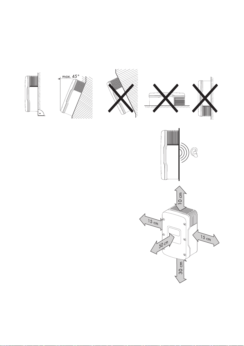
• Vertical installation or tilted backwards by max. 45 °.
• Never install the device with a forward tilt.
• Do not mount in a horizontal position.
• The connection area may not point upwards.
• In a living area, do not mount the unit on
plasterboard walls etc. in order to avoid audible
vibrations.
The Sunny Island can make noises when in use
which can be considered a nuisance when installed
in a living area.
• Observe the minimum clearances to walls as well
as to other devices and objects as shown in the
illustration.
24 SI5048-TEN093630 Technical Description
Page 25
SMA Solar Technology AG Mounting the Device
4.2 Mounting the Sunny Island with a Wall Mounting Bracket
CAUTION!
Risk of injury due to the Sunny Island falling during transport.
Physical injury (fractures or crushing) and damage to the Sunny Island.
• Consider the weight of the Sunny Island (63 kg).
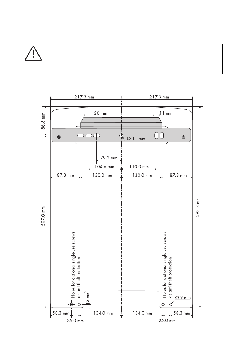
1. Mark the position of the drill holes using the wall mounting bracket and drill the holes.
Use 2 to 4 of the 6 holes in the middle of the wall mounting bracket.
Technical Description SI5048-TEN093630 25
Page 26
Mounting the Device SMA Solar Technology AG
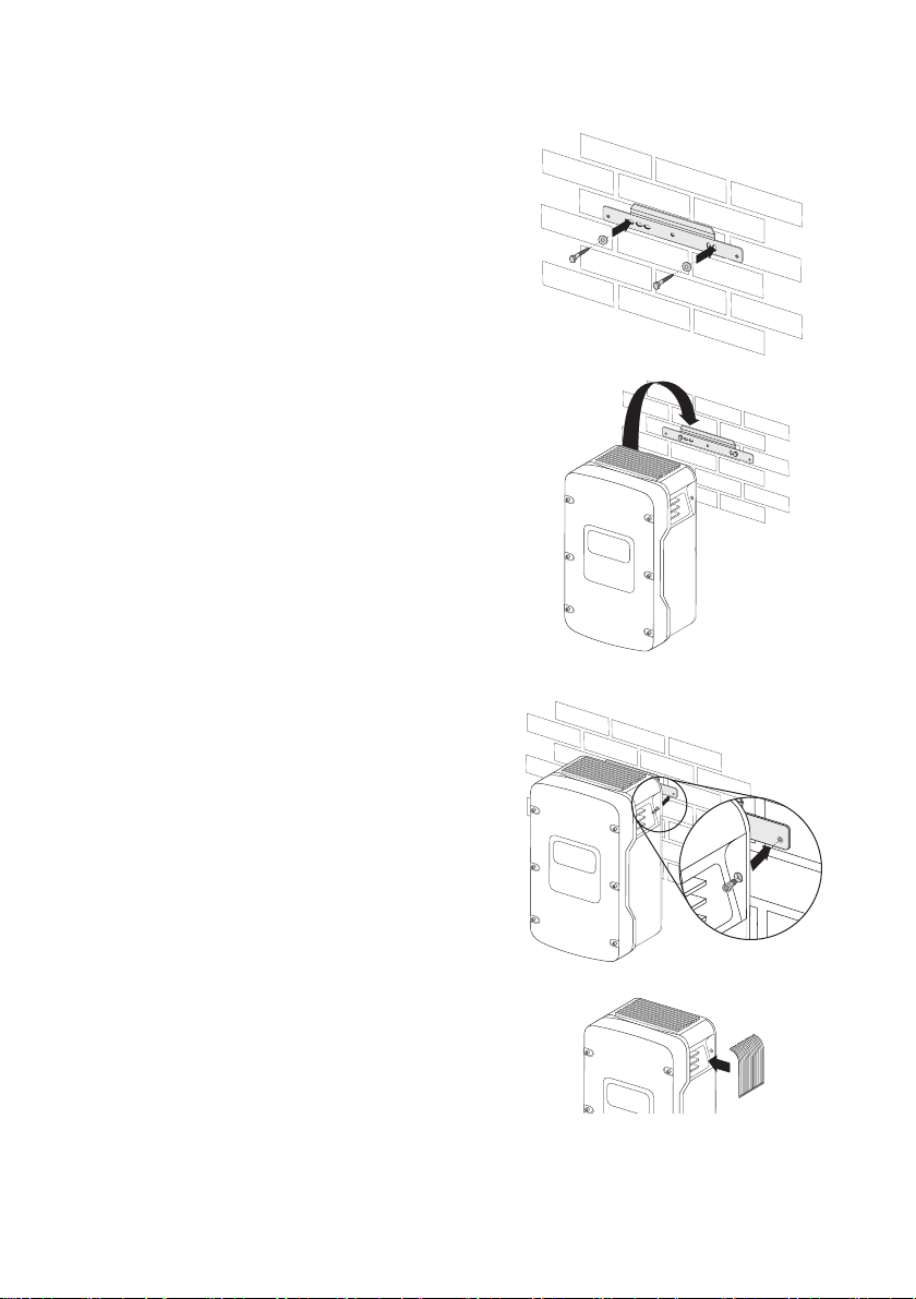
2. Secure the wall mounting bracket to the wall using
appropriate screws and washers.
3. Hang the Sunny Island onto the wall mounting
bracket using the opening in its rear for this
purpose.
4. Screw the Sunny Island to the wall mounting
bracket on both sides using the screws (M6x8)
provided. Only tighten the screws by hand.
☑ The Sunny Island is now mounted on the wall.
5. Make sure it is securely in place.
6. Close the recessed grips with the air grills provided.
To help you identify the sides, the air grills are
marked with "links/left" or "rechts/right" on the
inside.
26 SI5048-TEN093630 Technical Description
Page 27
SMA Solar Technology AG Opening and Closing
5 Opening and Closing
The enclosure of the Sunny Island has a removable lid. Remove this cover only when installing the
device or for required maintenance or repair work.
5.1 Opening the Sunny Island
1. Stop the Sunny Island as described in section 9.2”Stopping the Sunny Island (Standby)”
(page61).
2. Disconnect the Sunny Island from voltage sources as described in chapter 9.4”Disconnect the
device from voltage sources” (page62).
3. Ensure that the system cannot be accidentally switched on again.
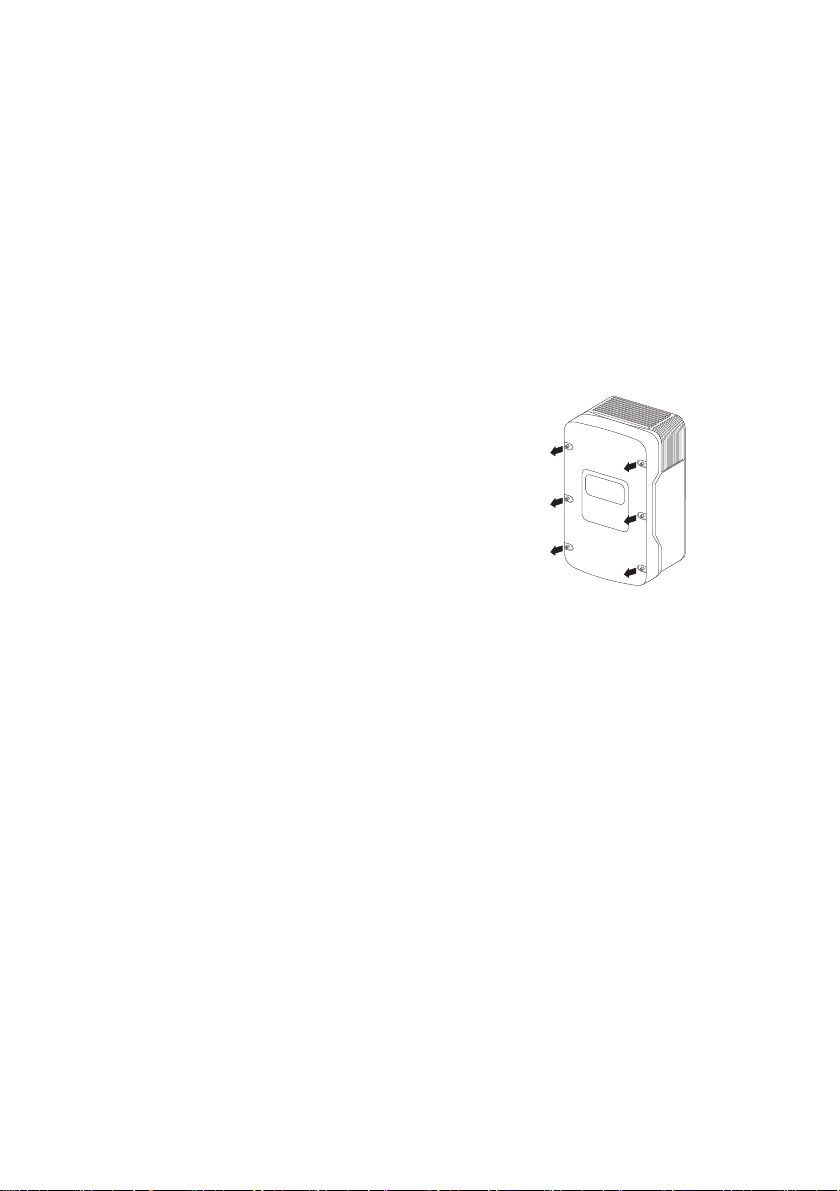
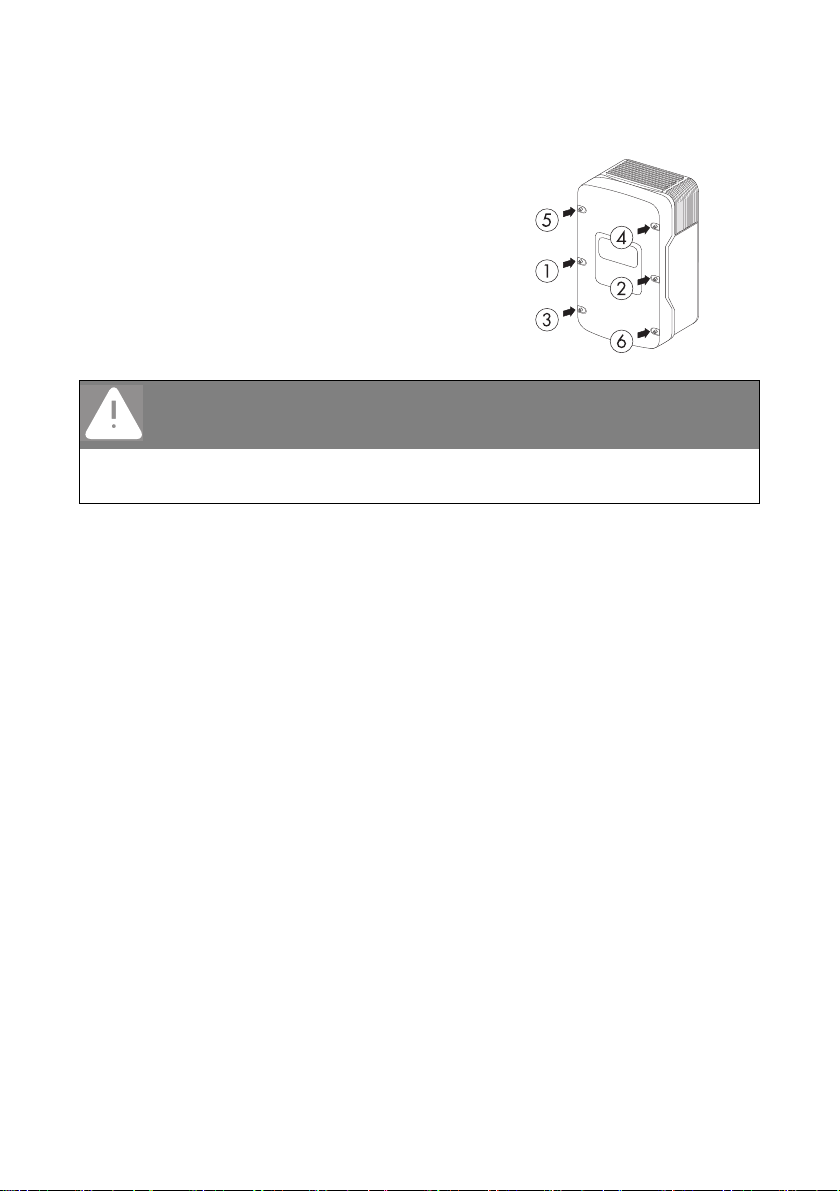
4. Loosen all 6 screws on the enclosure lid and set
them aside.
5. Remove the enclosure lid and set it aside.
☑ The Sunny Island is open.
Technical Description SI5048-TEN093630 27
Page 28
Opening and Closing SMA Solar Technology AG
5.2 Closing the Sunny Island
1. Place the enclosure lid onto the enclosure and
secure with the 6 screws and the corresponding
washers.
Tighten the screws with 6 Nm torque in the order
shown on the right hand side. The toothing of the
washers must face toward the enclosure lid.
DANGER!
Electric shock due to live enclosure lid. Death or serious burns.
The grounding of the enclosure lid is ensured by the toothed washers.
• Fasten the washers for all six screws with the toothing facing toward the enclosure lid.
2. Commission the Sunny Island as described in section 9.1”Activation” (page60).
☑ The Sunny Island is closed and in operation.
28 SI5048-TEN093630 Technical Description
Page 29
SMA Solar Technology AG Electrical Connection
6 Electrical Connection
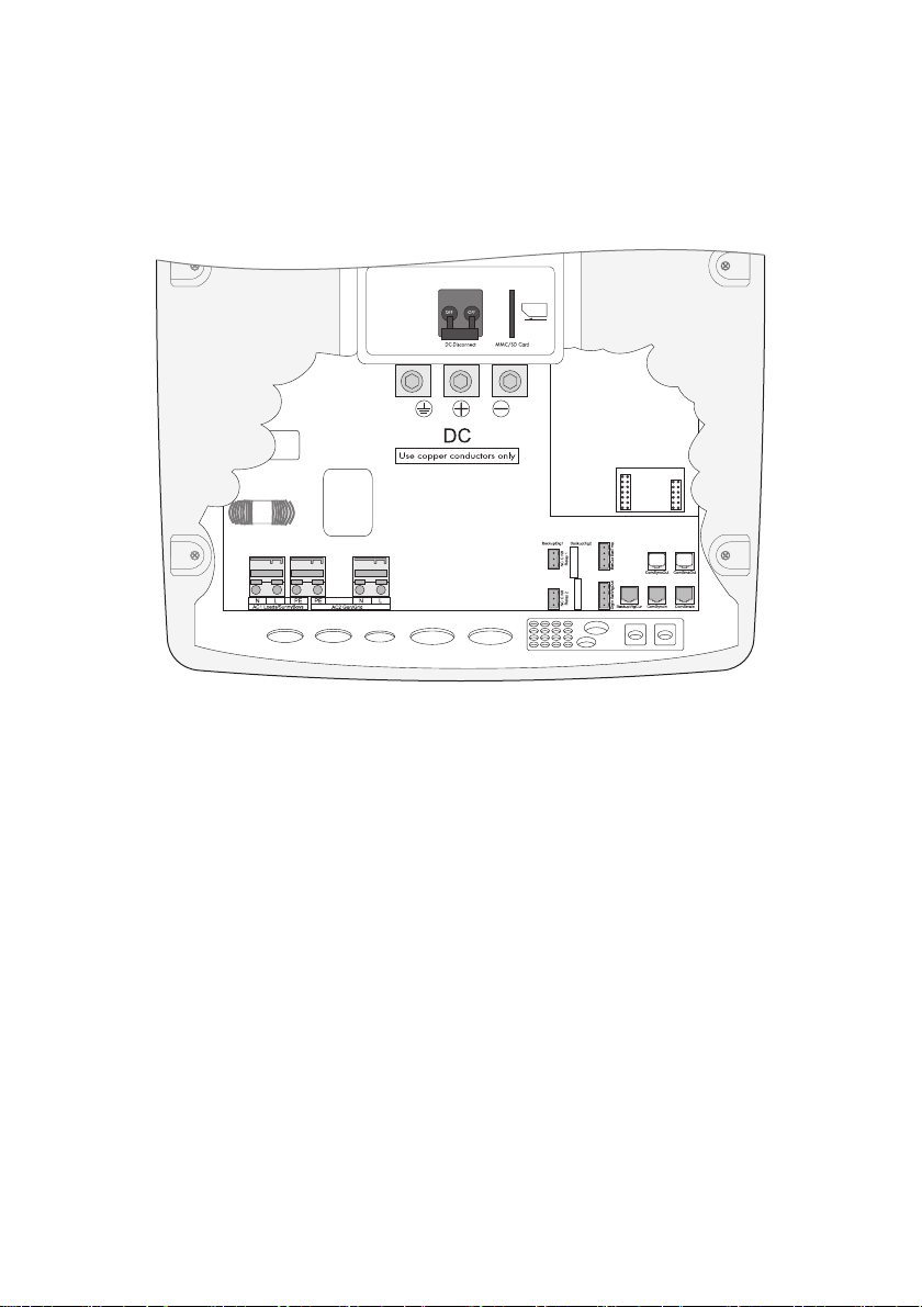
All cables are fed through the openings on the bottom side of the device (see next illustration) and
connected to the appropriate connection terminals on the Sunny Island.
Use the provided cable screw connections to fasten the cables inside the Sunny Island enclosure in a
manner conforming to the appropriate standards. The metric-thread cable screw connections
guarantee a dust-free and waterproof installation of the cables in the enclosure and also provide
strain relief for the cable connection. Close all unused openings in the enclosure using the appropriate
filler plugs.
Obtain an overview of the different components and connection areas of the Sunny Island
2.2”At a glance” (page17)).
Technical Description SI5048-TEN093630 29
Page 30
Electrical Connection SMA Solar Technology AG
6.1 Connection to ground
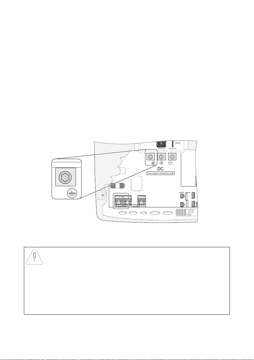
Before commissioning the Sunny Island it must be externally grounded according to the relevant
regulations. To allow different types of grounding, the N connection of the Sunny Island is not
connected to PE at the factory. However, since a connection bet ween N and PE is required for correct
operation, this must be done outside of the device.
Due to filter measures in the device, increased leakage currents against PE can always occur. For this
reason, a "fixed connection" of ground must be implemented according to EN 50178. Ground the
Sunny Island with a copper conductor (at least 10 mm² cross-section), or with two separate copper
conductors with a cross-section of at least 4 mm² each.
Wiring of the (Protective) Ground
In stand-alone configurations, the (protective) ground of the Sunny Island and its individual
components must be wired as a TN grid only. Be sure to observe all applicable regional
standards and guidelines.
External grounding
External grounding of the negative pole of the batteries is possible, because the batteries
and the grid side are galvanically isolated within the Sunny Island. In this case make sure
that the high currents that may occur under fault conditions can be adequately discharged.
If a ground connection is necessary, establish it separately outside of the Sunny Island.
Calculating the Required Grounding Cable Cross-Section
SMA Solar Technology cannot state generally valid values for the cross-section of the cable required
for the external grounding of the battery. The cable dimensions depend on the type and size of the
battery connected, the external fuse (DC side) and the material used in the grounding conductor.
Determining the cross-section
Exact calculation of the grounding conductor cross-section must take account of the
regionally applicable standards and guidelines.
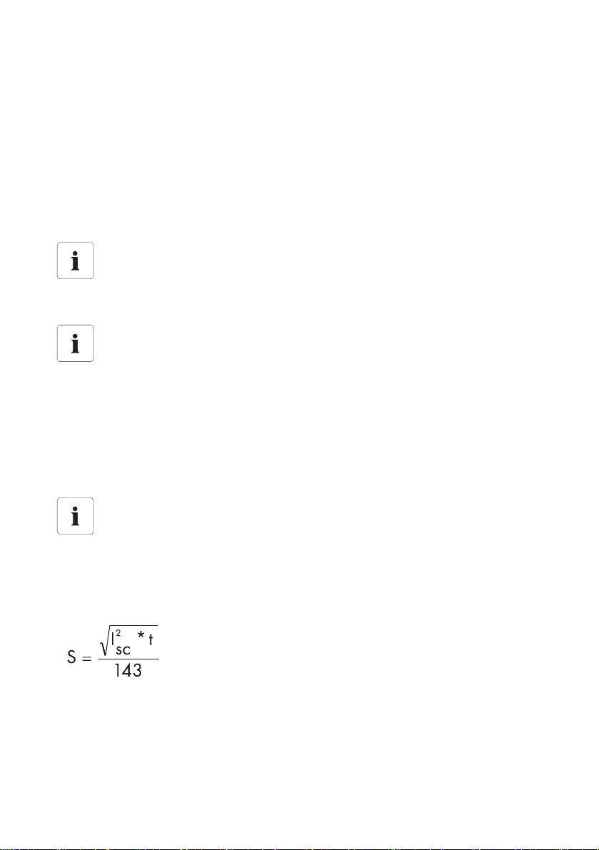
The required cross-section of a (copper) grounding conductor can be calculated using the following
formula. Trigger times for short-circuit currents of between 2,000 A and 10,000 A are typically
about 25 ms.
t = interruption time in seconds
ISC= Maximum battery current (short-circuit current) in
amperes
S = conductor cross-section in mm²
A grounding conductor of 16 mm² cross-section is thus adequate for short-circuit currents up to
10,000 A.
30 SI5048-TEN093630 Technical Description
Page 31
SMA Solar Technology AG Electrical Connection
Th e DC gro und ing c ond uct ors mus t be connected to the connection labeled "Ground". The grounding
cable is installed in five steps:
1. Loosen the cable screw connection on the Sunny Island.
2. Thread the grounding conductor through the cable screw connection.
3. Remove the protective insulation from the conductor and fit a suitable ring cable lug to the
exposed end of the conductor.
4. Install the cable screw connection with the M20 adapter piece (inc luded in del ivery ) at the third
cable feed-through from the right.
– Introduce the cable screw connection with the thread in the cable feed-through.
– Screw the counter-nut onto the cable screw connection thread on the inside of the housing
and tighten.
5. Attach the conductor with the ring cable lug to the ground connection terminal and tighten the
screw with a torque of 4 to 5.7 Nm.
6.2 DC connection
NOTICE!
Function impairment of devices on the DC side.
The Sunny Island is NOT suitable for use with DC supply grids.
Function impairment can occur on devices installed on the DC side of a Sunny Island with
cables exceeding 30 meters and with a flexible connection.
• Only use fixed installations.
• Do not use cables of lengths greater than 30 meters between the Sunny Island and
the battery and/or DC device.
Technical Description SI5048-TEN093630 31
Page 32
Electrical Connection SMA Solar Technology AG
6.2.1 Safety Precautions/Conditions
Connect a suitable battery to the DC side (see section 22”Technical Data” (page205)). The DC
connection must observe all applicable local ordinances and guidelines.
DANGER!
Death hazard due to inappropriate handling of the battery. Death or serious
chemical burns.
• Obasrve all safety and maintenance instructions provided by the battery
manufacturer!
• Use special (insulated) tools to mount and install the battery.
6.2.2 Cable Sizing
Be sure to observe all standards applicable to the installation site. The DIN VDE 0298-4 applies in
Germany.
Use as short a battery cable as possible. Long cables and insufficient cable diameters reduce the
system efficiency and the overload capabilities.
Example of Cable Layout
At an AC output of 5000 W and a battery voltage of 48 V, a curret of up to 140 A flows through
the battery cable.
The current flowing through the battery cable causes a power loss and a drop in voltage with every
meter of simple battery cable. You can use the following table to find the powe r loss and vo ltage drop
associated with different cable cross sections.
Cable cross-section power loss Voltage drop
2
35 mm
50 mm
70 mm
2
2
12 W/m 90 mV
8.5 W/m 60 mV
6 W/m 45 mV
This means that:
For a 10-meter distance between the Sunny Island and the battery, at least 20 m of cable are needed.
Using a cross section of 50 mm
2
, 140 A (current flowing through the battery cable) cause a power
loss of 170 W in total and an effective voltage drop of 1.2 V.
32 SI5048-TEN093630 Technical Description
Page 33
SMA Solar Technology AG Electrical Connection
6.2.3 Cable protection
In addition to the internal DC circuit breakers, install a separate, external fuse as close as possible to
the battery. Install a suitable fuse plug for the fuse according to the maximum specified DC current
(e.g NH1 at 250 A).
DANGER!
Risk of lethal electric shock! Death or serious burns.
If no external cable protection is available, observe the following:
• Lay the DC cables so that they are ground- and short-circuit-proof.
• If there are short-circuit currents of over 10,000 A, use an additional fuse.
6.2.4 Connection
DANGER!
Danger to life due to high voltages Death or serious burns.
• Connect the external fuse and the battery cable to the battery only after all
installation work has been completed.
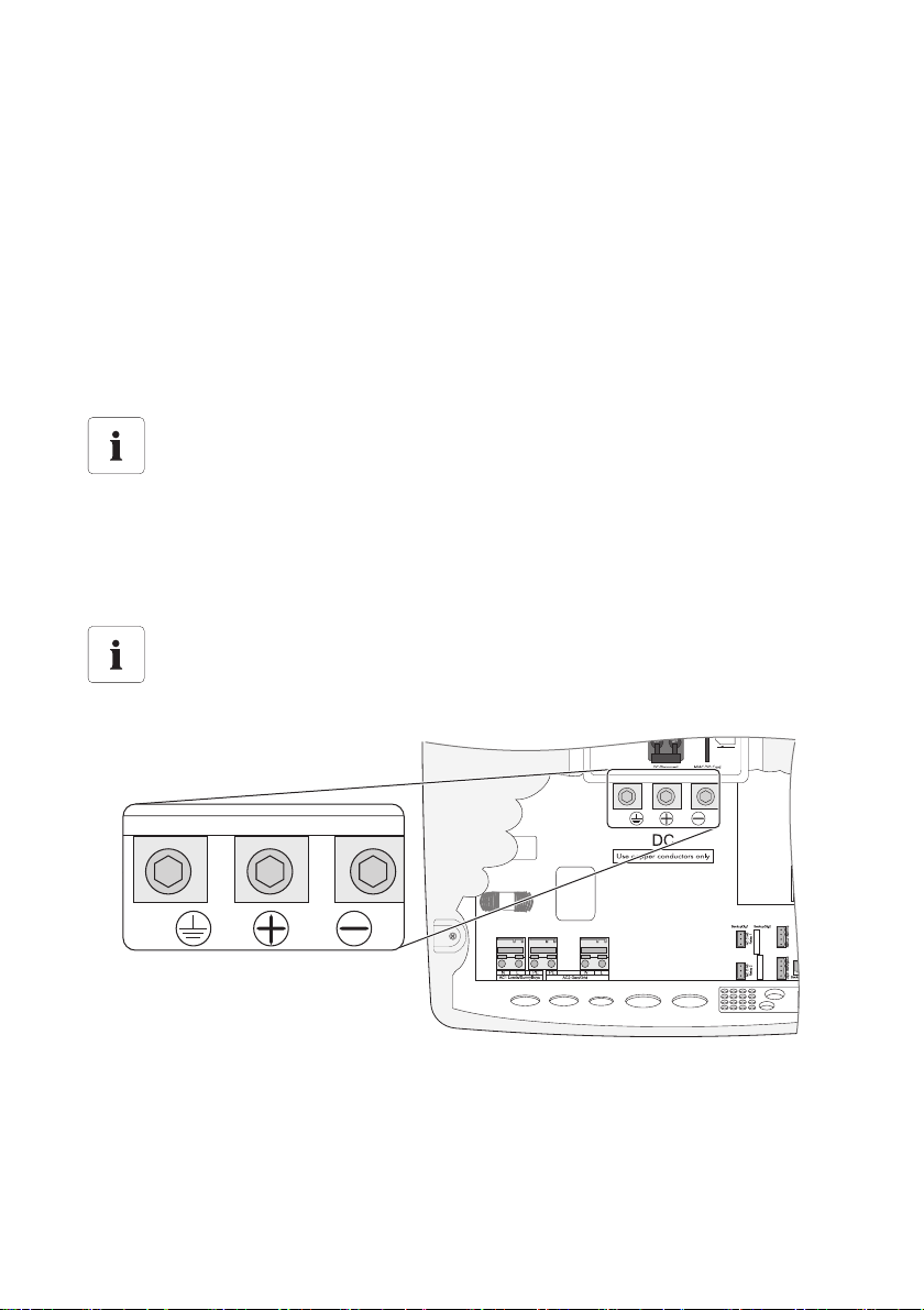
There is a "DC − " and a "DC +" connection available for each ring cable lug (max. 70 mm²) for the
battery feed cables in the Sunny Island.
Technical Description SI5048-TEN093630 33
Page 34
Electrical Connection SMA Solar Technology AG
Install the DC connections in the following sequence:
1. Loosen the cable screw connection on the Sunny Island.
2. Thread the DC cable through the cable screw connection.
3. Remove the protective insulation from the conductor and fit a suitable ring cable lug to the
exposed end of the conductor.
4. Install the M32 cable screw connection (included in delivery) fo r "D C−" and "DC +" in the cab le
feed-throughs.
– Introduce the cable screw connection with the thread in the cable feed-through.
– Screw the counter-nut onto the cable screw connection thread on the inside of the housing
and tighten.
DC- connection area
The areas between the ring cable lug and the connection area must be clean. This way a
transition resistance is avoided and the heating of the terminals is reduced.
5. A tta ch t he " DC −" c abl e wi th t he r ing cab le l ug t o th e "DC − " connection terminal and tighten the
screw with a torque of 4 to 5.7 Nm.
6. Attach the "DC+" cable with the ring cable lug to the "DC+" connection terminal and tighten the
screw with a torque of 4 to 5.7 Nm.
DC cables
Do not connect any other components to the DC cables. Other components must be
connected directly to the battery via separate cables.
34 SI5048-TEN093630 Technical Description
Page 35
SMA Solar Technology AG Electrical Connection
6.3 AC Connection
6.3.1 Cable protection
Use a sub-distribution unit in order to connect the Sunny Island to the stand-alone grid and any other
external which may be available.
Provide the sub-distribution unit with appropriate line circuit br eak ers , an d ob ser ve a ll l oca l no rms and
regulations.
NOTICE!
Destruction of the Sunny Island due to overvoltages at the AC input.
• Do not exceed the maximum input current of 56 A.
The Sunny Island is not equipped with an all-pole isolator. The neutral conductor (N conductor) is
looped through the device and the N connection terminals of AC1 and AC2 are connected inside the
Sunny Island.
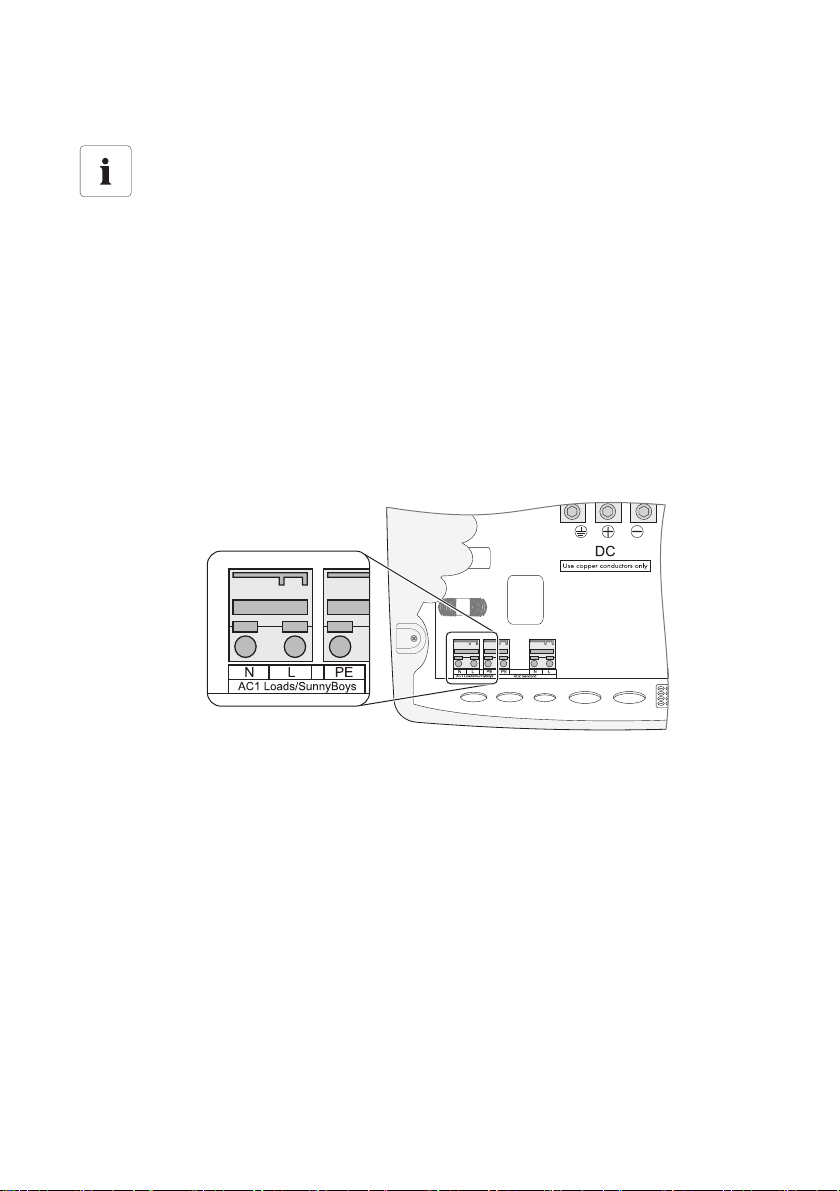
6.3.2 AC1 (Loads/Sunny Boys)
The stand-alone grid sub-distribution (e.g., loads, PV inverter, wi nd tu rbi ne i nve rte r) i s co nne cte d to the
AC1 output of the Sunny Island.
If you want to secure individual load circuits separately, you must use circuit breakers of maximum
16 A and with a type B trigger characteristic. If there is a short circuit the Sunny Island can trigger this
circuit breaker. If larger fuses, or fuses that blow more slowly are used, the Sunny Island cannot trip
these. In these cases be sure to install a residual current device (RCD) in order to avoid dangerous
body currents.
Connection in a single-phase parallel system
Connect all single-phase parallel Sunny Island with the same cross-sections and cable
lengths. Connect all AC inputs in parallel.
Connecting in a three-phase parallel system
Always install the master at phase L1, slave 1 at L2 and slave 2 at L3. This installation
results in a right-hand rotary field.
Failure of one phase within a three-phase system
If a phase fails within a three-phase grid, the cluster continues to run. In order to protect
your loads, you may require phase monitoring or a motor overload switch.
Technical Description SI5048-TEN093630 35
Page 36
Electrical Connection SMA Solar Technology AG
For connection, proceed as follows:
Cable cross-section
The maximal cable cross section for the load connections / PV inverter is 16 mm
1. Thread the 3-pole conductor through the cable screw connection and then through the cable
conduit inside the Sunny Island.
2. Install the M25 metric-thread cable screw connection (included in delivery) onto the
"AC1 Loads/Sunny Boys" cable feed-through.
– Introduce the cable screw connection with the thread in the cable feed-through.
– Screw the counter-nut onto the cable screw connection thread on the inside of the housing
and tighten.
3. Remove the protective insulation from each of the three cables.
4. Connect PE to the "AC1 Loads/Sunny Boys" according to the label.
5. Connect N and L to the "AC1/Sunny Boys" according to the label.
2
.
36 SI5048-TEN093630 Technical Description
Page 37
SMA Solar Technology AG Electrical Connection
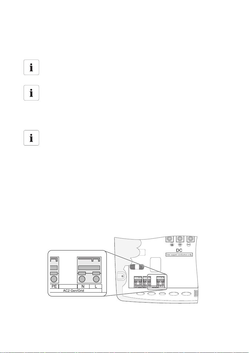
6.3.3 AC2 (Generator/Grid)
The sub-distribution of the generator/power distribution grid is connected to the AC2 output of the
Sunny Island.
Single-phase parallel system
In the case of parallel single-phase systems also connect the generator or the grid to all
slaves on AC2. The cable cross-sections and cable lengths used must be identical.
Three-phase system
Always install the master at phase L1, slave 1 at L2 and slave 2 at L3. This installation
results in a right-hand rotary field.
The system does not monitor additional fuses. Check any additional fuses regularly!
For connection, proceed as follows:
Cable cross-section
The maximal cable cross section for the generator is 16 mm².
1. Thread the 3-pole conductor through the cable screw connection and then through the cable
conduit inside the Sunny Island.
2. Install the M25 metric-thread cable screw connection (included in delivery) onto the
"AC2 Gen/Grid" cable feed-through.
– Introduce the cable screw connection with the thread in the cable feed-through.
– Screw the counter-nut onto the cable screw connection thread on the inside of the enclosure
and tighten.
3. Remove the protective insulation from each of the 3 cables.
4. Connect PE to the "AC2 Gen/Grid" according to the label.
5. Connect N and L to the "AC2/Sunny Boys" according to the label.
Technical Description SI5048-TEN093630 37
Page 38
Electrical Connection SMA Solar Technology AG
6.4 Additional Connections
For installing the connections described below, feed the cables through the specified holes in the
cable insert. Plugs for sealing the RJ45 communication cable for internal and external communication
are provided in the cable insert upon delivery. Combining plugs allows you to establish 0 to 4 feedthroughs (2 plugs without a feed-through, 1 with 1 feed-through and 2 with 2 feed-throughs). Remove
any of these to connect the communication cable.
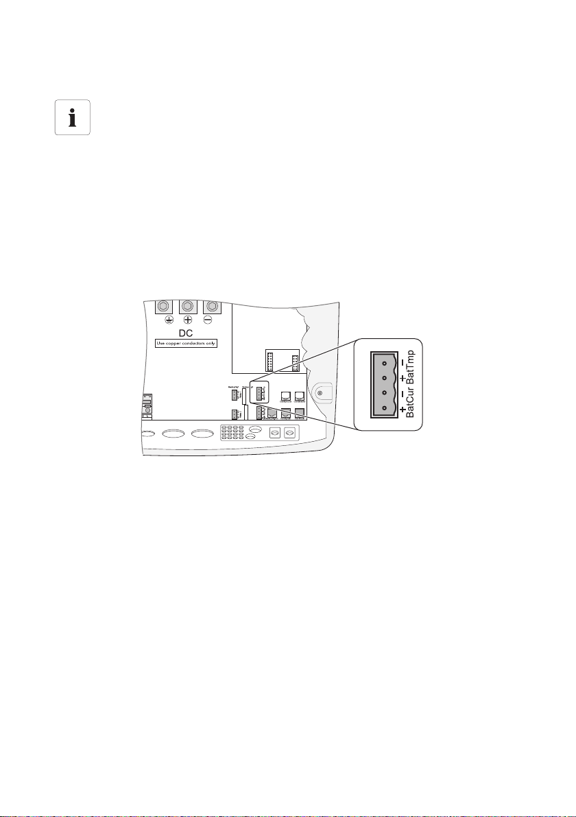
6.4.1 Battery temperature sensor
The battery temperature sensor measures the temperature of the connected battery. This is necessary
since the optimum charging voltage for a battery strongly depends on the temperature. Further
information is provided in section 13.4”Charge control” (page94).
A battery temperature sensor must be connected in order to operate the battery temperature sensors
(included in the delivery). In case of a fault (short circuit, cable break), the Sunny Island operates in
a safe setting, which over time leads to insufficient battery charging. A warning indicating that the
defective battery temperature sensor should be replaced immediately is shown on the display.
NOTICE!
Destruction of the battery and battery temperature sensor.
• Use only the battery temperature sensor included in the delivery.
• Attach the battery temperature sensor externally to one of the battery cells. Choose
a place where the heat generation during operation is the greatest.
Battery temperature sensor in a cluster
A battery temperature sensor is provided with each Sunny Island. Only one battery
temperature is needed for one cluster. It is connected to the corresponding master.
38 SI5048-TEN093630 Technical Description
Page 39
SMA Solar Technology AG Electrical Connection
For connection, proceed as follows:
Polarity of the cables
The polarity of the two cables is irrelevant for the functioning of the battery temperature
sensor.
1. Poke through the appropriate place in the cable insert with a pointed object.
2. Starting from the outside, feed the cable with cable end sleeves through the hole in the
Sunny Island.
3. Connect the cables correspondingly to the "BatTmp" connection of the 4-pole print terminal
included in the delivery.
4. Tighten the terminals.
5. Insert the 4-pole print terminal into the "BatTmp" socket on the Sunny Island.
6. Attach the battery temperature sensor externally to one of the battery cells. Choose a spot
between two cells or as close as possible to such a spot. This place should be in the middle area
of the battery tank, because that is where heat generation is greatest during operation.
Technical Description SI5048-TEN093630 39
Page 40
Electrical Connection SMA Solar Technology AG
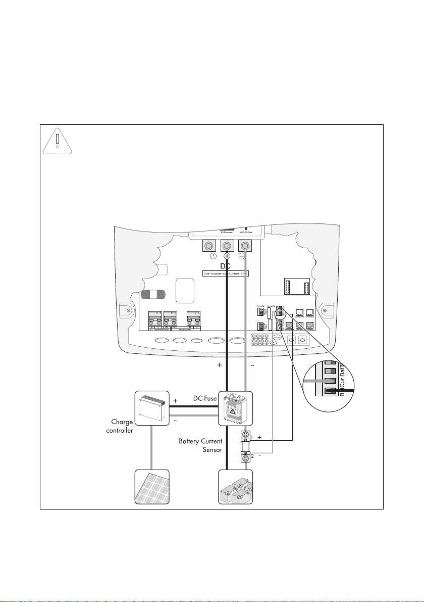
6.4.2 Battery Current Sensor
In addition to the internal measurement, the Sunny Island provides the possibility to measure the
battery current via a shunt. You need this function if you intend to operate additional DC generators
and DC loads in your off-grid system. Only one battery current sensor connected to the respective
master is required for a cluster.
NOTICE!
Damage to the battery due to the connection of additional DC generators or DC
loads to the off-grid system.
In this operating situation, the internal current measurement of the Sunny Island works
imprecisely; the charge state of the battery is not determined exactly.
• Install an external battery current sensor (shunt).
Example:
40 SI5048-TEN093630 Technical Description
Page 41
SMA Solar Technology AG Electrical Connection
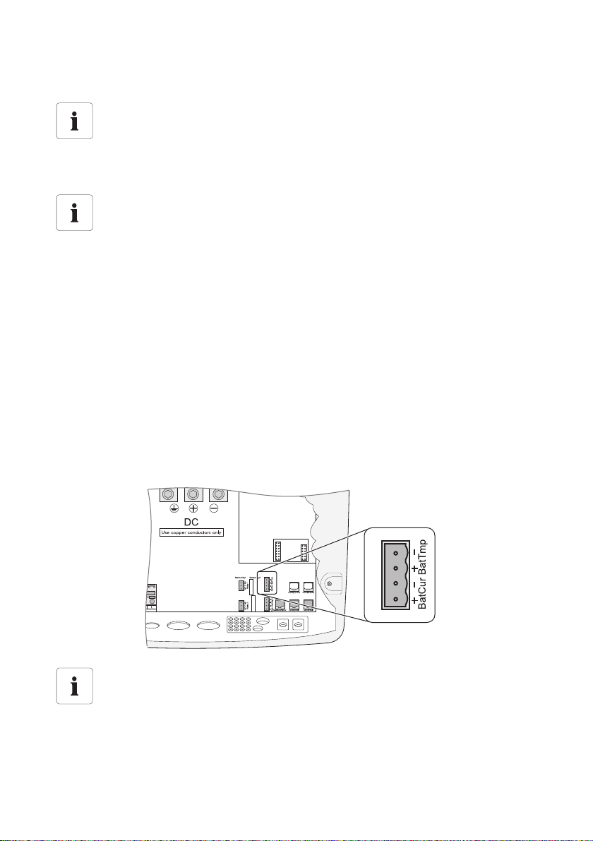
Connecting the Battery Current Sensor:
Use cables of intrinsically safe circuits
Always use cables of intrinsically safe circuits for the connection of battery current sensors.
"Intrinsically safe" means here that the cable is double-insulated and that the wire melts but
the insulation remains intact in the event of a short circuit. In addition, the cable is not
combustible. In order to avoid measuring errors, make sure to use twisted cables.
Installation notice
The battery current sensor must be looped around the negative pole of the battery.
In addition, the contact of that battery current sensor which is co nne cte d to the Sunny I sla nd
(1) must be connected to the terminal "BatCur+" (see following figure).
• Positive battery current means that the battery is discharging
(current from the battery)
• Negative battery current means that the battery is charging (current into the battery)
1. Poke through the appropriate place in the cable insert with a pointed object.
2. Starting from the outside, feed the cable with cable end sleeves through the hole in the
Sunny Island.
3. Connect the cables correspondingly to the "BatCur" connection of the 4-pole print terminal
included in the delivery.
4. Tighten the terminals.
5. Insert the 4-pole print terminal into the "BatCur" socket on the Sunny Island.
☑ The battery current sensor is installed.
Commissioning the battery current sensor
When connecting a battery current sensor to the Sunny Island the device's internal offset
must be adjusted during the first commissioning of the off-grid system. To do this, proceed
as described in section 8.3”Commissioning the battery current sensor” (page58).
Technical Description SI5048-TEN093630 41
Page 42
Electrical Connection SMA Solar Technology AG
6.4.3 Communication for Multi-device Connection
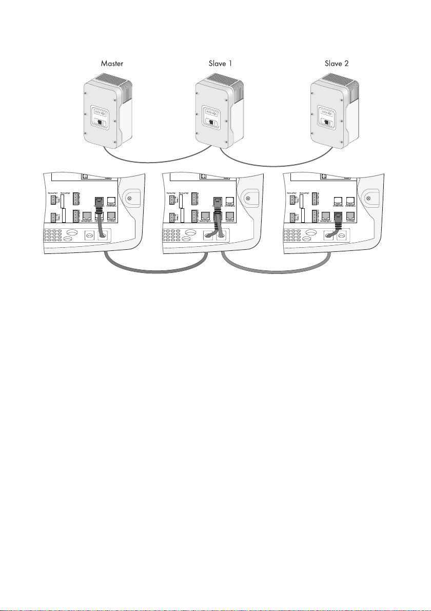
The Sunny Island can be connected in parallel or in a three-phase system with other Sunny Islands in
order to increase the overall power. The Sunny Island communicate with other via an RJ45 cable.
A black RJ45 cable is provided with each Sunny Island. You need the cable in order to establish an
(internal) communication between several Sunny Islands. The maximal total length of the
communication bus cannot exceed 30 m. If you operate only one Sunny Island in your system, the
cable is not required.
Proceed as follows to implement the connection:
1. Remove one of the two plugs in the rubber terminal area.
2. Feed the RJ45 cable from the outside through the plugs inside the Sunny Island master.
3. Remove the terminating resistor from the "ComSyncOut" socket of the master and plug it into the
"CompSyncIn" socket of the master.
4. Plug the RJ45 cable into the "ComSyncOut" socket.
5. Connect the Sunny Island master to the slave:
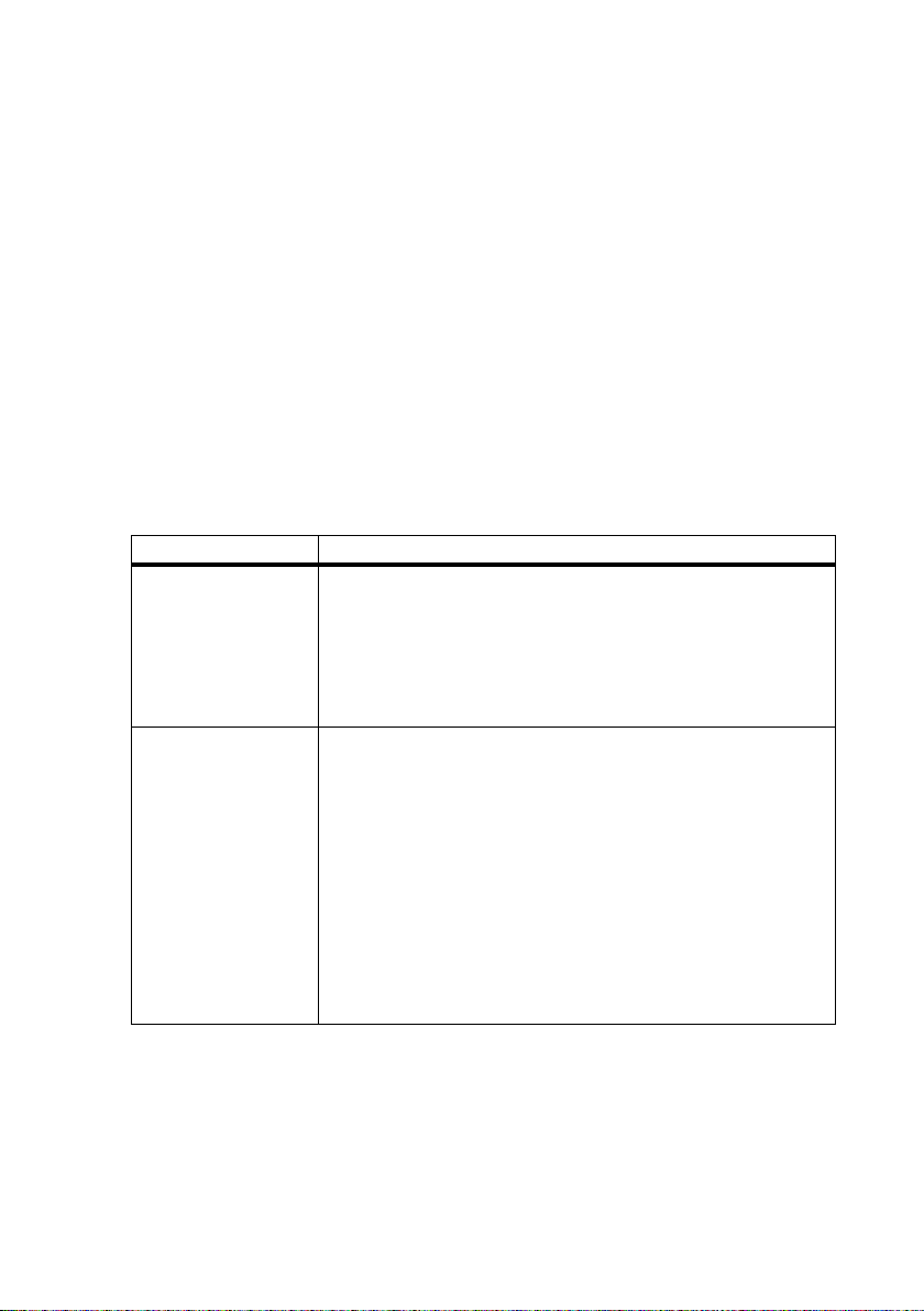
Number of Slaver Connection Procedure
1 slave • Take the RJ45 cable leading away from the master, introduce
it into the Sunny Island slave and plug it into the "ComSyncIn"
socket.
• Leave the termination resistor plugged into the "ComSyncOut"
socket.
☑ The Sunny Island master and slave are connected.
2 slaves • Take the RJ45 cable leading away from the master, introduce
it int o th e Su nny Isl and sla ve 1 and plu g it int o th e "C omS ync In"
socket there.
• Remove the terminating resistor from the "ComSyncOut" socket
in the Sunny Island slave 1.
• Plug the RJ45 cable included in the delivery into the
"ComSyncOut" socket of the slave 1.
• Tale the RJ45 cable leading away from the slave 1, introduce
it int o th e Su nny Isl and sla ve 2 and plu g it int o th e "C omS ync In"
socket there.
☑ The Sunny Island master and the slaves are connected.
42 SI5048-TEN093630 Technical Description
Page 43
SMA Solar Technology AG Electrical Connection
Technical Description SI5048-TEN093630 43
Page 44
Electrical Connection SMA Solar Technology AG
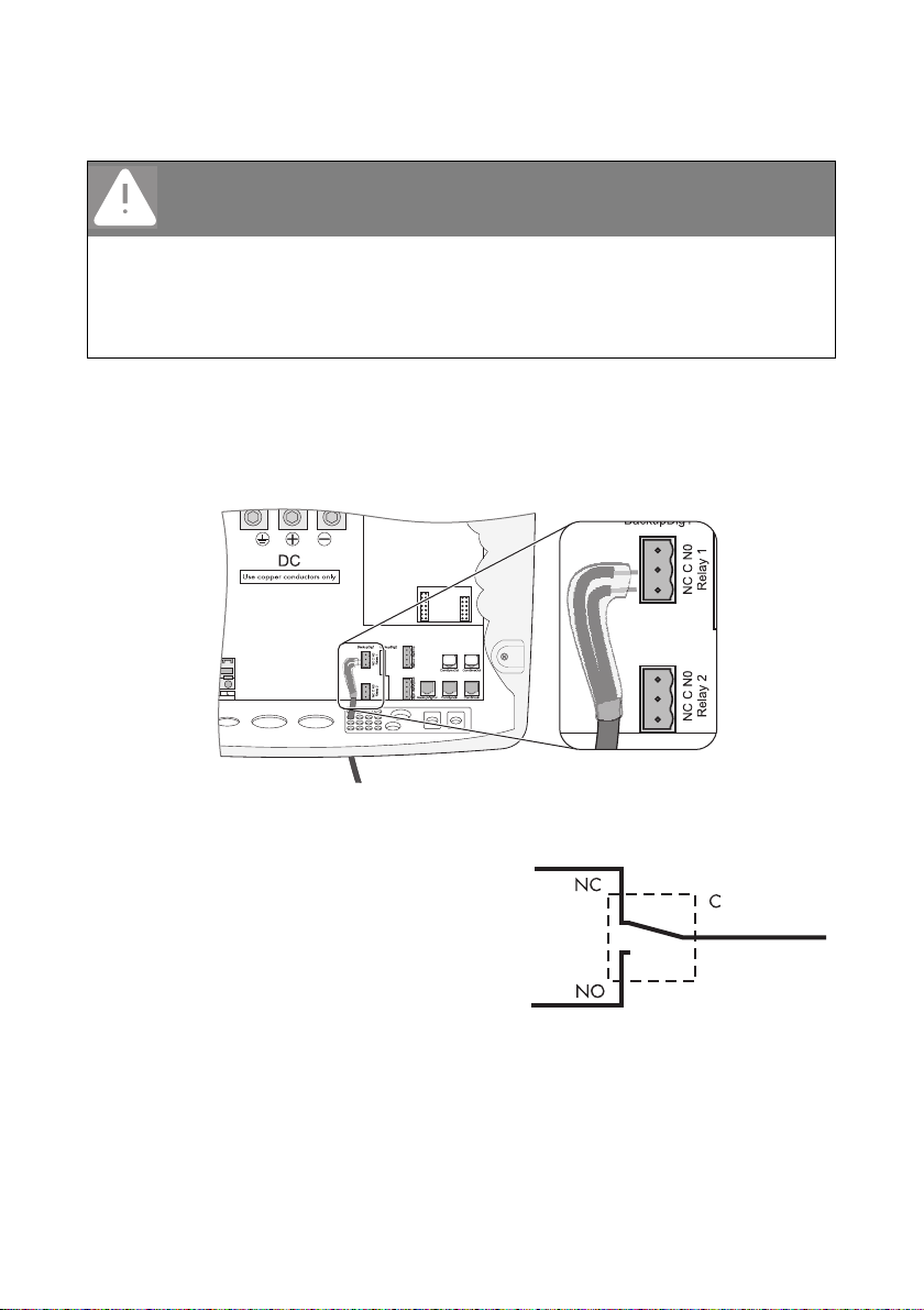
6.4.4 Multi-function Relays 1 and 2
The Sunny Island offers you several options for the control of internal and external processes.
For this purpose, two multi-function relays are integrated into th e Su nny Isl and to w hic h yo u can ass ign
functions via the using the "241.01 Rly1Op" and "241.02 Rly2Op" parameters (see chapter
15”Relays” (page123)).
We recommend connecting the load shedding and generator request functions to the master, since,
if a failure occurs, the slave may be waiting for a confirmation, but the master continues to operate
and the device can at least operate in a limited capacity.
Operating principles of the relays
The relays are changeover contacts; they can be used as normally closed contacts (NCC)
or as normally open contacts (NOC).
You can only assign one function to each relay!
44 SI5048-TEN093630 Technical Description
Page 45
SMA Solar Technology AG Electrical Connection
For connection to the relay contact, proceed as follows:
DANGER!
Death hazard due to faulty insulation Death or serious injuries.
• Securely disconnect the relay cable from the communication area and the AC area.
• Strip the wires of the relay cable.
• Sheathe all relay cables installed using the silicone tube provided.
• Do not operate the device without the silicone tube.
1. Poke through the appropriate place in the cable insert with a pointed object.
2. Starting from the outside, feed the cable with cable end sleeves through the hole in the
Sunny Island.
3. Cut an appropriate piece from the silicone tube (in delivery) and pull it over the wires.
4. Connect the corresponding wires to the 3-pole print terminals included in the delivery. The pins
have the following meaning:
– NC: Normally closed (closed when idle)
– C: Contact (operating contact)
– NO: Normally opened (open when idle)
5. Tighten the terminals.
6. Insert the 3-pole print terminal into the corresponding socket on the Sunny Island.
Technical Description SI5048-TEN093630 45
Page 46
Electrical Connection SMA Solar Technology AG
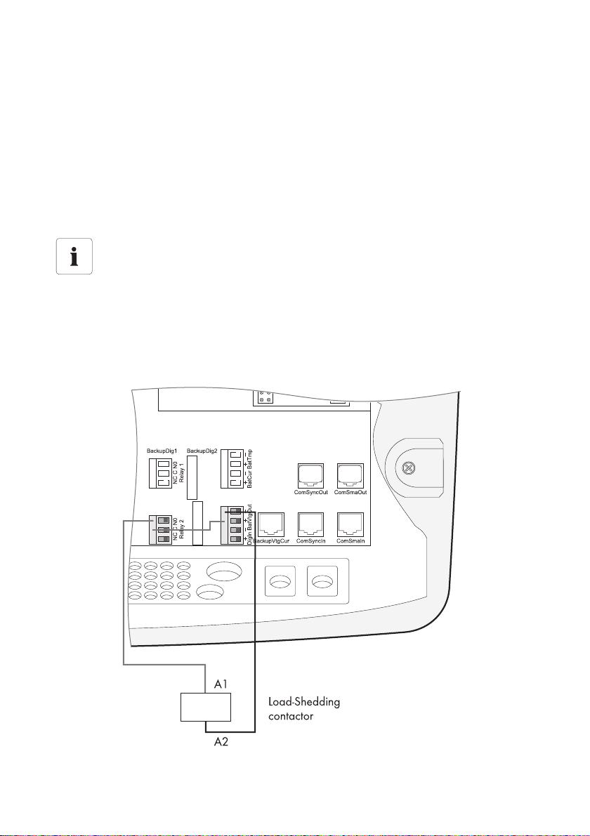
Power contactor for load shedding
The Sunny Island can automatically switch off loads to protect the batteries from deep discharge.
To do this, an external (AC or DC) power contactor must be installed between the Sunny Island and
the loads (see also section 21”Accessories” (page204)).
Installation of the load shedding system is strongly recommended in systems with extensive AC-side
coupling of solar power or wind power. This is the only way to achieve safe operation of the system,
even in cases of low energy generation or very high consumption. Disconnect only the loads, never
disconnect the generators (e.g., PV inverters)!
Installing the Power Supply of a DC Power Contactor for Load Shedding (e.g., relay2):
Power supply of the DC power contactor
A 48 V voltage is present in the battery-supplied control circuit.
The voltage can handle loads up to a maximum of 600 mA.
1. Wire the A1 coil connector of the power contactor to the connection terminal NO (relay2).
2. Wire connection terminal C (relay2) to the connection terminal "BatVtgOut +".
3. Wire the A2 coil connector of the power contactor to the connection terminal "BatVtgOut − ".
☑ The control circuit of the power contactor is installed.
46 SI5048-TEN093630 Technical Description
Page 47
SMA Solar Technology AG Electrical Connection
Generator Start
The Sunny Island can control generators. The Suny Island directly supports generators that can be
started/stopped using a single contact. Generators which require more than one contact must be
connected to the Sunny Island via a Generator Manager (GenMan). This product can be acquired
through SMA Solar Technology.
Default setting of the relays
By default, relay 1 is set to the generator start function "AutoGn" and relay 2 is set to the
load shed function "AutoLodSoc".
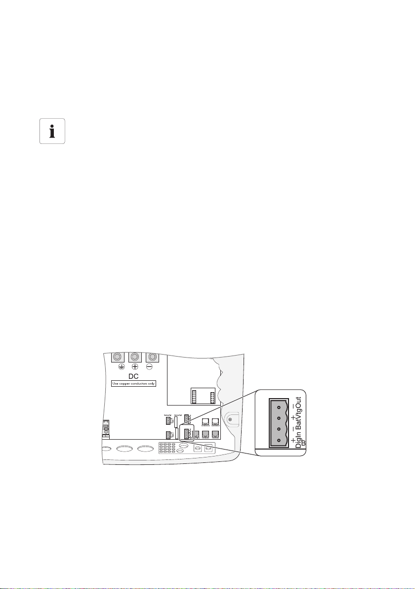
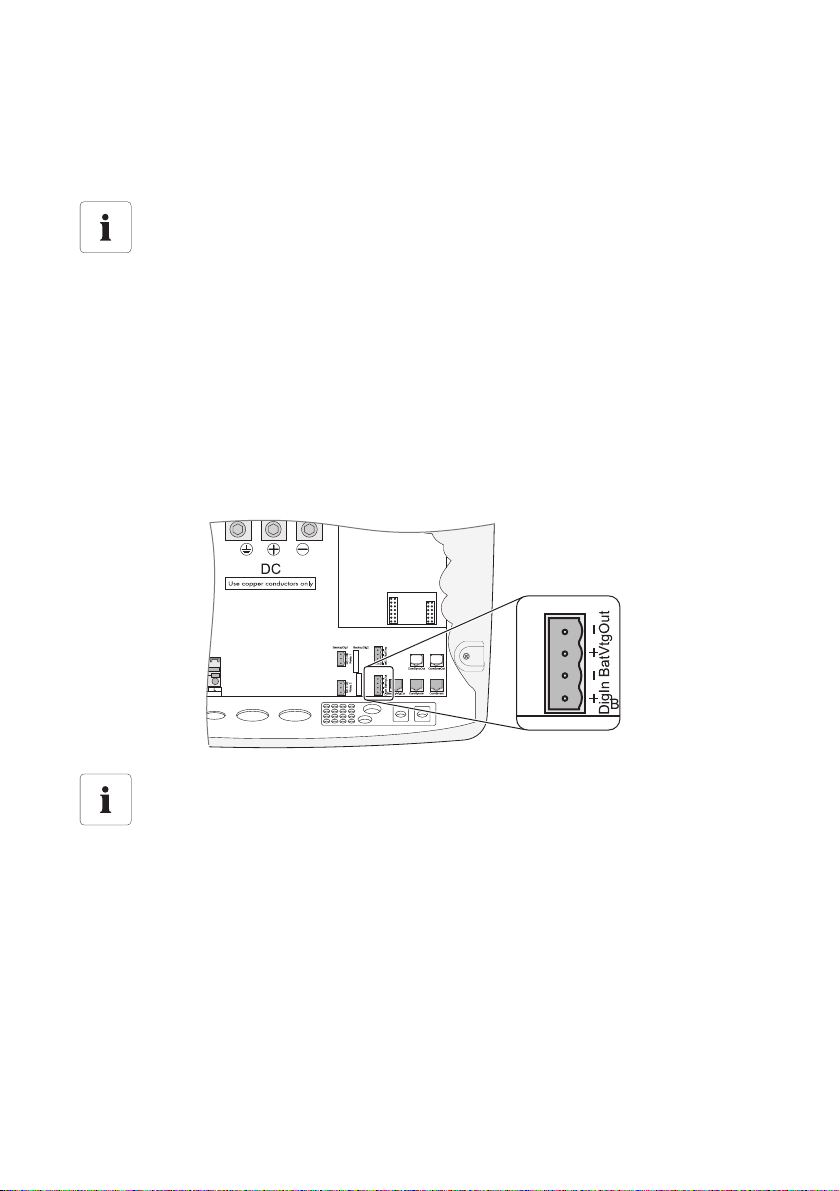
6.4.5 BatVtgOut Power Supply
The battery voltage is conducted to the outside at these terminals. The battery voltage is fused at both
poles by PTC resistors (max. 0.6 A). Depending on the internal temperature of the Sunny Island, the
triggering threshold is at over 0.6 A.
This connection can be used, for example, to supply a DC contactor for load shedding.
For connection, proceed as follows:
1. Poke through the appropriate place in the cable insert with a pointed object.
2. Starting from the outside, feed the cable with cable end sleeves through the hole in the
Sunny Island.
3. Connect the cables correspondingly to the "BatVtgOut" connection of the 4-pole print terminal
included in the delivery.
4. Tighten the terminals.
5. Insert the 4-pole print terminal into the "BatVtgOut" socket on the Sunny Island.
Technical Description SI5048-TEN093630 47
Page 48
Electrical Connection SMA Solar Technology AG
6.4.6 DigIn Digital Input
These terminals are used as a digital input for external electrical sources. For example, the feedback
contact for the GenMan (GenRn) is connected here.
Related Functions
If you connect a GenMan, or operate the system with the generator and grid (GenGrid)
in parallel, use the relays on the master device in order to activate the respective functions.
For connection, proceed as follows:
1. Poke through the appropriate place in the cable insert with a pointed object.
2. Starting from the outside, feed the cable with cable end sleeves through the hole in the
Sunny Island.
3. Connect the cables correspondingly to the "DigIn" connection of the 4-pole print terminal
included in the delivery.
4. Tighten the terminals.
5. Insert the 4-pole print terminal into the "DigIn" socket on the Sunny Island.
Further information
For more information on connecting and operating the GenMan, see the technical
description of the GenMan.
48 SI5048-TEN093630 Technical Description
Page 49
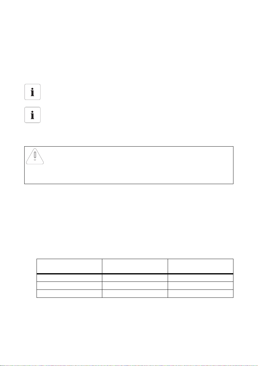
SMA Solar Technology AG Electrical Connection
6.5 Interface for External Communication
You can connect SMA Solar Technology communication devices (e.g., Sunny Boy Control, Sunny
WebBox) or a PC with the appropriate software to a communication interface. A detailed wiring
diagram can be found in the communication device manual, of the software or on the Internet at
www.SMA.de/en.
You can incorporate an RS485 communication interface into the Sunny Island.
Powerline modem
Communication via Powerline/Powerline modem is not possible in an off-grid system.
Communication in a cluster
Fitting of a communication interface in a cluster is only necessary on the master.
6.5.1 Connection of the Interface
NOTICE!
Electrostatic discharges can damage the communication interface.
Internal components of the Sunny Island can be irreparably damaged by static discharge.
• Ground yourself before touching a component.
For connection, proceed as follows:
1. Remove the right plug of the two plugs in the rubber terminal area.
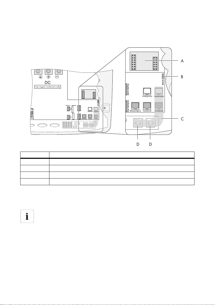
2. Feed the cable from the outside through the cable conduit (D) into the Sunny Island master.
3. Plug the cable into the "ComSmaIn" socket.
4. Place the plug around the cable.
5. Reinsert the plug in the opening provided in the rubber terminal area.
6. Lay the cable in area (C).
7. Connect the cable. Assignment pins in the RJ45 socket:
Assignment SubD Communication Device
2A (Data+)3
5GND2
7B (Data−)6
8. The RS485 data bus of the Sunny Island is terminated with a terminating resistor.
This terminating resistor is already plugged into the "ComSmaOut" socket. Please only remove
the plug if you want to connect another communication device.
Technical Description SI5048-TEN093630 49
RS485 - signal assignment RJ45 - socket -
Sunny Island
Page 50
Electrical Connection SMA Solar Technology AG
9. Move the slide switch (B) to RS485 (lower position).
10. Plug the communication interface onto the board (A).
Position Description
A Slot for communication interface
B Sliding switch to set the type of communication
C Cable route
D Enclosure feed-through in the base of the Sunny Island
Data Transmission Speed
The Sunny Island can be operated at different data transmission rates to communicate with external
devices. The parameter "250.06 ComBaud" must be set correspondingly.
Setting the baud rate
If PV inverters are connected to the communication bus, then the baud rate must be set to
1200 bps (factory setting).
50 SI5048-TEN093630 Technical Description
Page 51
SMA Solar Technology AG Control Elements
7 Control Elements
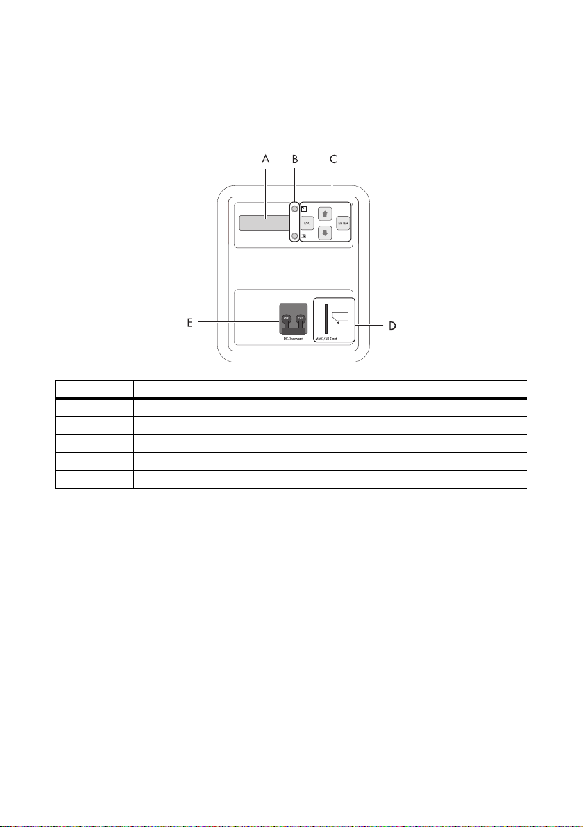
In order to commission the Sunny Island, you should familiarize yourself with its operation
beforehand. The individual control elements can be seen in the following figure.
Position Description
ADisplay
BLEDs
C Control buttons
D Slot for the SD card
E DC Circuit Breaker
Technical Description SI5048-TEN093630 51
Page 52
Control Elements SMA Solar Technology AG
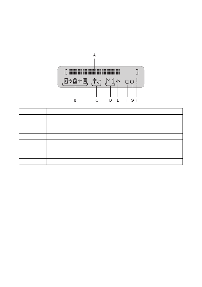
7.1 Display Messages
The display of the Sunny Island has two lines, each with 16 characters. For details, please see section
10.6”Display Messages (Overview)” (page74).
Position Description
A Output power / charging power (load status)
B Direction of energy flow and system status
CGrid status
D Device assignment
E Status of the external source (star, question mark or exclamation mark)
FRelay 1 status
G Relay 2 status
H Warning message (exclamation mark)
7.2 DC Circuit Breaker
The DC circuit breaker is used to switch on/off as well as disconnect the Sunny Island on the DC side.
For details, see section 9”Activation and Deactivation” (page60).
52 SI5048-TEN093630 Technical Description
Page 53
SMA Solar Technology AG Control Elements
7.3 Buttons
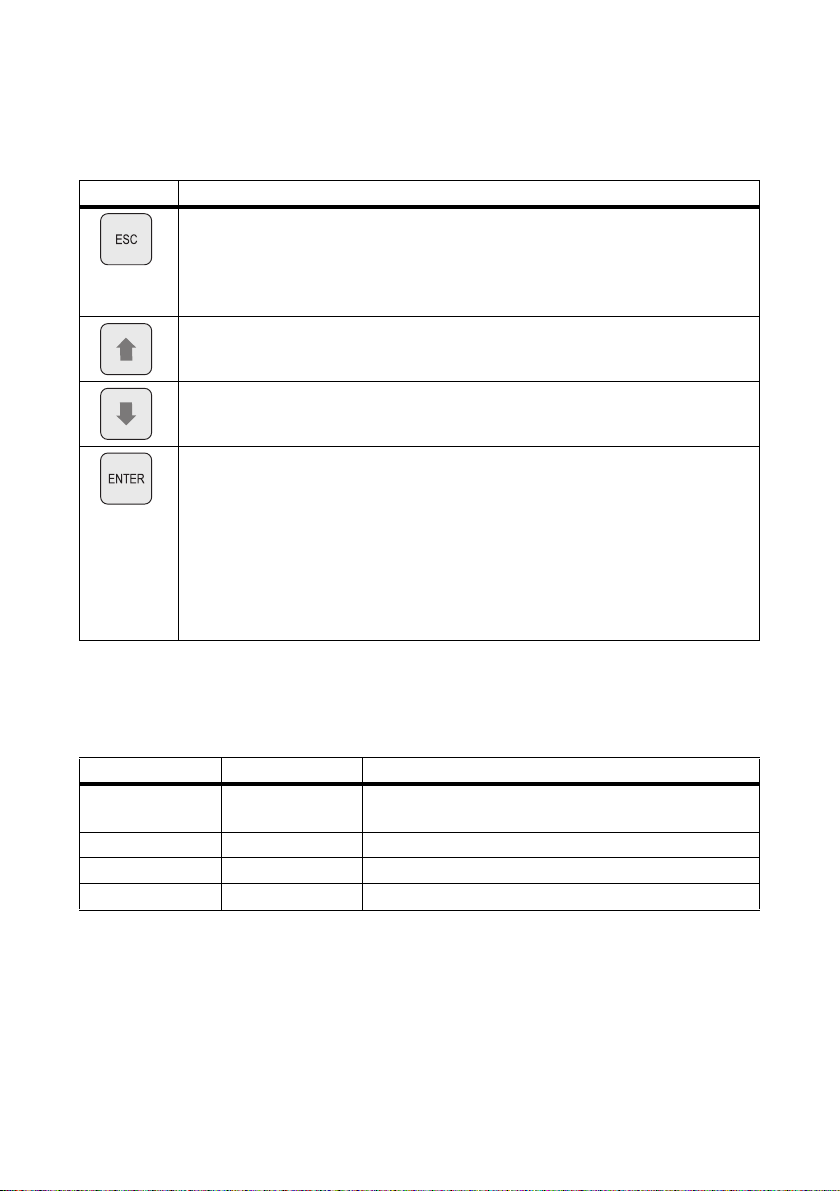
The table explains the functions of the buttons on the Sunny Island:
Button Function
cancels the selected function
answers NO
navigates one menu level higher
stops device (when held pressed down)
navigates up one list element, increases data value
navigates down one list element, decreases data value
select function
Select value
confirms the change
answers YES
navigates one menu level down
starts device (when held pressed down)
stops device (when held pressed down)
7.4 Meaning of the Light Emitting Diodes (LEDs)
In the Sunny Island control panel, there is both a green (above) and a red (below) light emitting diode
(LED). Their functions are described on this table:
Green LED Red LED Operating state
––standby or off
(no inverter operation)
ON – Operation
– ON Disturbance or Fault
ON ON Initialization
7.5 SD card
The Sunny Island features an SD card which can be used for updating firmware and as a service
interface. For details, see section 11”Archiving Data on an SD Card” (page80).
Technical Description SI5048-TEN093630 53
Page 54
Initial Commissioning SMA Solar Technology AG
8 Initial Commissioning
8.1 Requirements
Check the connections
Before starting the commissioning process, make sure all electrical connections have the
correct polarity and are connected according to the instructions.
Always save data
Always use the SD card to save data and events. In case of a failure SMA Solar
Technology can thus quickly help you.
The Quick Configuration Guide (QCG) allows you to quickly install and commission your off-grid
system. To do so, use the menu to select the 'right' system for you. The display then shows a selection
via which the parameters can be set specifically.
54 SI5048-TEN093630 Technical Description
Page 55
SMA Solar Technology AG Initial Commissioning
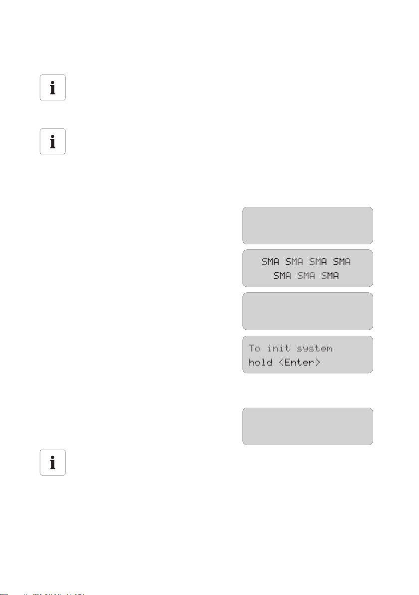
SIBFSBOOT V1.004
SI5048
@SMA 2009
01#StartMenu
Start System
8.2 Starting the Quick Configuration Guide (QCG)
Occurrence of an error
If the Sunny Island displays an error message unexpectedly, this error must be fixed before
the Sunny Island can be put into operation. For this purpose, refer to section
20”Troubleshooting” (page184).
Default setting of parameters
Upon starting the Quick Configuration Guide, viable parameter values are set by default.
The QCG is automatically activated during the initial startup of the Sunny Island. In this case begin
with point 3. If the QCG is not activated automatically, begin with point 1.
1. Switch the Sunny Island's DC circuit breaker to the "ON" position.
☑ The Sunny Island initiates the startup phase.
The notific ations shown her e are i ssued . The last
notice is issued as soon as the start phase is
completed.
2. Press and hold down <ENTER> until the Sunny Island beeps three times.
☑ The QCG is started.
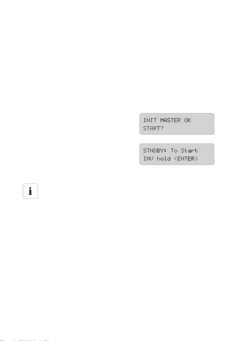
Systems with several Sunny Islands
If you have a system with more than one Sunny Island, you must first run the QCG on the
slave(s) before starting the master device (display message "INIT MASTER OK START?").
Only the device type is set there. Start the master only after you have done this!
– "Start System" (if you have accidentally accessed the QCG and only would like to restart
the system)
Technical Description SI5048-TEN093630 55
Page 56
Initial Commissioning SMA Solar Technology AG
– "New System" (if you would like to start a new system or perform changes to the system
configuration)
– "New Battery" (if you wish to reset battery-specific parameters only. You cannot change
general parameters using "New Battery")
– "Emerg Charge" (if you would like to charge a deeply discharged battery using an
external source)
3. Use "New System" to set the following parameters:
– Device type (master, slave 1, slave 2, slave 3)
Systems with one Sunny Island
If only one Sunny Island is used in the system, the device type is set to "master" and is not
displayed.
–Voltage/frequency type (230V_50Hz, 220V_60Hz), default setting is "230V_50Hz"
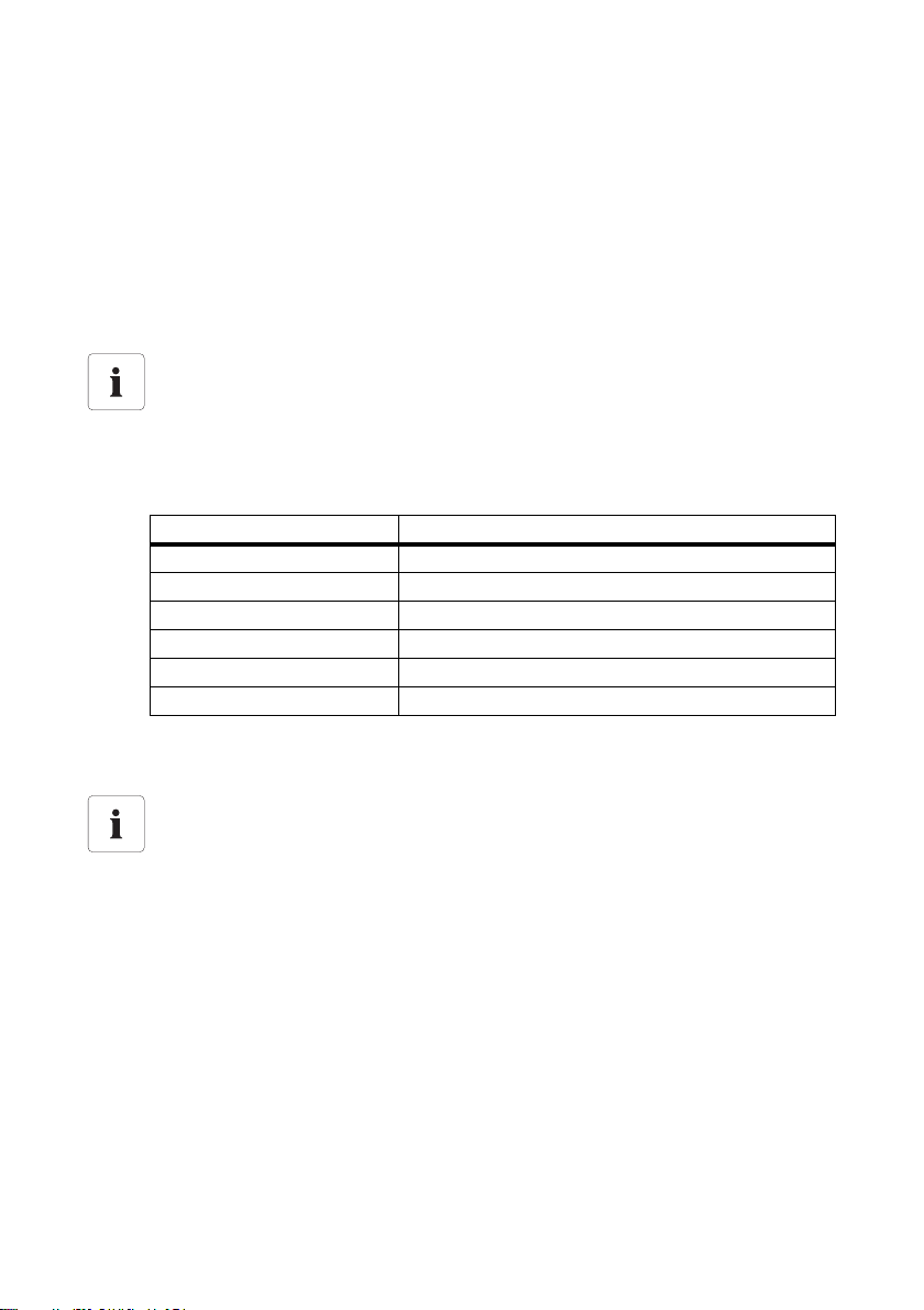
– System configuration (see table for setting options), preset to "1Phase1".
Displayed text Description
3Phase Three-phase system, 3 Sunny Islands
1Phase1 Single-phase system, 1 Sunny Islands
1Phase2 Single-phase system, 2 Sunny Islands
1Phase3 Single-phase system, 3 Sunny Islands
1Phase4 Single-phase system, 4 Sunny Islands
MC-Box Setting for multicluster operation
– date / time
– Battery type (VRLA, FLA, NiCd), default setting is "VRLA"
Battery types
VRLA: Valve Regulated Lead Acid
Closed lead acid batteries with immobilized electrolyte in gel or AGM (Absorbent Glass
Mat Separator) in all standard designs available on the market (grid plate, tubular plate,
small, large, AGM, Gel, etc.)
FLA: Flooded Lead Acid
Closed lead acid batteries with liquid electrolyte in all standard designs available on the
market (grid plate, tubular plate, small, large, etc.)
NiCd: Nickel-Cadmium
Pocket-type plate or fiber plate closed nickel cadmium batteries
– Nominal voltage of the battery (42 V - 52 V in 2-V steps for FLA and VRLA, 43.2 V to 48 V
in 1.2-V steps for NiCd), default setting: "48.0 V"
– Nominal battery capacity (100 Ah - 10000 Ah), default setting: "100 Ah"
56 SI5048-TEN093630 Technical Description
Page 57
SMA Solar Technology AG Initial Commissioning
– External power supply unit (PvOnly, Gen, Grid, GenGrid)
GenGrid:
– Maximum generator current (0 to 224 A), default setting is "16 A"
– Generator interface (Manual, GenMan, Autostart), default setting is "Autostart"
– Maximum grid current (0 to 224 A), preset to "16 A"
Grid:
– Maximum grid current (0 to 224 A), preset to "16 A"
4. The following parameters must be set when "New Battery" is selected:
– Battery type (VRLA, FLA, NiCd), default setting is "VRLA"
– Nominal battery capacity (100 Ah - 10000 Ah), default setting: "100 Ah"
☑ After entering all parameters the following
notice appears.
5. Press <ENTER> to confirm.
☑ The notifications shown here are issued.
6. Press <ENTER> until you hear a peep.
☑ The Sunny Island has started and is in operation.
Adjustable parameters
For more information on adjustable parameters, see section 19”Parameter lists”
(page137).
Note that some parameters can only be changed after entering the installer password
(see chapter 10.5”Entering the installer password” (page73)), or in standby mode
(see section 9.2”Stopping the Sunny Island (Standby)” (page61)).
Technical Description SI5048-TEN093630 57
Page 58
Initial Commissioning SMA Solar Technology AG
8.3 Commissioning the battery current sensor
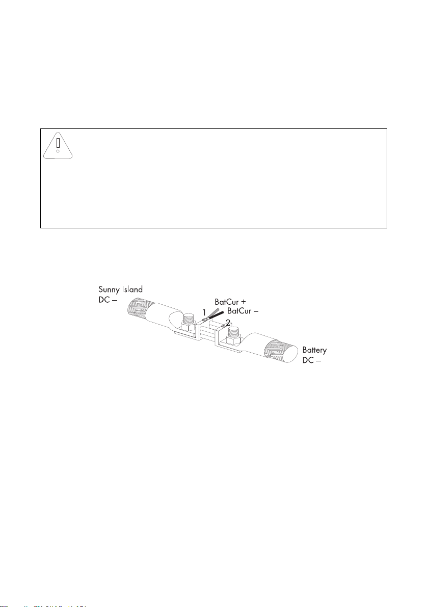
If you have installed a battery current sensor in your system you must synchronize the device's internal
offset. To do this, proceed as follows:
1. Put the Sunny Island on standby, as described in chapter 9.2”Stopping the Sunny Island
(Standby)” (page61).
NOTICE!
System error due to wrong parameters being entered.
All parameter settings which could affect the operating safety of the off-grid system are
protected by the installer password.
• Only qualified personnel are permitted to set and adjust system parameters.
• Enter the password as described in section 10.5”Entering the installer password”
(page73).
2. Short-circuit the battery current sensor cables.
– BatCur+ to terminal 1
– BatCur − to terminal 1
3. Set the following parameters:
Choose the type of battery current sensor:
– "225.01 BatCurSnsTyp" (None / 50 mV / 60 mV). Only after activation of the parameter
with 50 mV or 60 mV will other parameters (02, 03 and 04 in the menu "225# Battery
Current Sensor") be shown and activated.
4. Set the nominal current for the battery current sensor (e.g., 400 A / 60 mV):
– "225.02 BatCurGain60" (for a 60 mV output)
– "225.03 BatCurGain50" (for a 50 mV output)
5. Start the self-calibration:
– set "225.04 BatCurAutoCal" to "Start"
☑ The Sunny Island conducts a self-calibration.
6. Check the offset error:
"120.06 TotBatCur" should be (close to) zero.
58 SI5048-TEN093630 Technical Description
Page 59
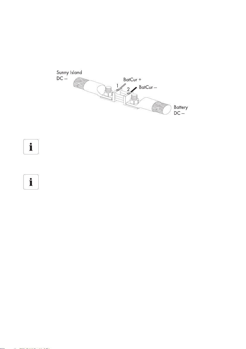
SMA Solar Technology AG Initial Commissioning
7. Connect the battery current sensor cables correctly again, as shown on the graphic.
Make sure the wires have the correct polarity when doin this.
– BatCur+ to terminal 1
– BatCur − to terminal 2
8. Start the Sunny Island (see section 9.1”Activation” (page60)).
9. Check the current direction: "120.06 TotBatCur"
Current direction: Discharging the battery
• No generator/grid connected
• Loads are being supplied
The value of the battery current is positive.
Current direction: Charging the battery
• Generator/grid connected
• Loads are not/are marginally supplied
• Battery is being charged
The value of the battery current is negative.
Technical Description SI5048-TEN093630 59
Page 60
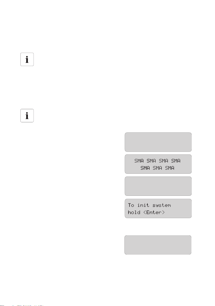
Activation and Deactivation SMA Solar Technology AG
SIBFSBOOT V1.004
SI5048
@SMA 2009
01#StartMenu
Start System
9 Activation and Deactivation
9.1 Activation
Systems with several Sunny Islands
Switch the slaves on before the master. To do this, proceed as follows.
1. Check the following requirements:
– correct electrical connections
– voltages and polarities
2. Switch the DC circuit breaker of the Sunny Island to the "ON" position.
☑ The display of the Sunny Island lights up.
Parameter "250.01 AutoStr"
Even with the "250.01 AutoStr" parameter set, the Sunny Island must be manually started
after each time the device is switched on using the DC circuit breaker.
☑ The Sunny Island initiates the startup phase.
The notific ations shown her e are i ssued . The last
notice is issued as soon as the start phase is
completed.
3. Start QCG. Press and hold down <ENTER> until the Sunny Island beeps three times.
☑ The QCG is started and the notice shown here
is displayed. Continue as in chapter
8.2”Starting the Quick Configuration Guide
(QCG)” (page55).
or
60 SI5048-TEN093630 Technical Description
Page 61
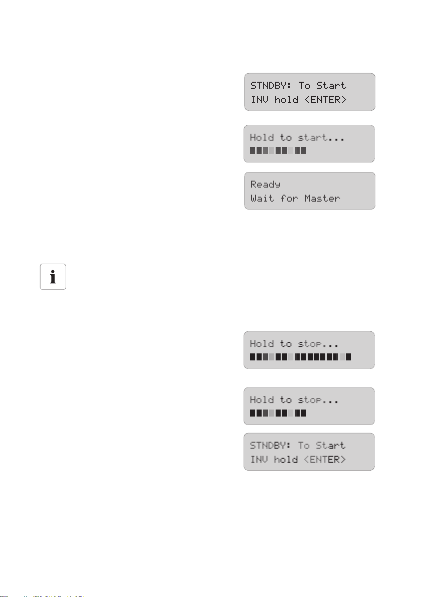
SMA Solar Technology AG Activation and Deactivation
4. Wait 5 seconds.
☑ The Sunny Island skips the QCG and the notice
shown here is displayed.
5. Presss <ENTER> and hold.
☑ The remaining time is shown on the display as
beams.
☑ On a slave the notice shown here is shown until
the master is started.
6. Press <ENTER> on the master.
☑ There is peep. The Sunny Island is in operatin and the green (top) LED is on.
9.2 Stopping the Sunny Island (Standby)
Standby
Even in standby mode the Sunny Island still requires about 4 W of power from the battery.
Proceed as follows to stop the Sunny Island:
1. Press <ENTER> or <ESC> to stop the Sunny Island.
☑ The notifications shown here are issued.
2. Press and hold <ENTER>.
☑ The remaining time is shown on the display as
beams.
☑ T he S unn y Is lan d is sto ppe d. T he n otific ati on s how n
here are issued.
Technical Description SI5048-TEN093630 61
Page 62

Activation and Deactivation SMA Solar Technology AG
9.3 Switch off
To switch off the Sunny Island, proceed as follows:
"Disconnection sequence"
Only with the sequence shown here can you ensure that all internal counter positions/
values are saved.
1. Stop the Sunny Island as described in section 9.2”Stopping the Sunny Island (Standby)”
(page61).
2. Switch the Sunny Island's DC circuit breaker to the "OFF" position.
☑ The Sunny Island is switched off.
9.4 Disconnect the device from voltage sources
1. Switch off the Sunny Island as described in section 9.3”Switch off” (page62).
2. Disconnect the Sunny Island from the battery.
3. D isconn ect the Sun ny Is lan d fr om t he v olt age sou rce s (A C1 a nd AC2). Separate AC1 and AC2
and disconnect from voltage sources.
☑ If PV inverters are connected to AC1, these switch off automatically as soon as the island
grid is missing.
4. Check thatthe Sunny Island has been disconnected from voltage sources.
5. Wait at least 15 minutes to let the capacitors discharge and to allow the voltage inside the
device to drop to a safe level.
☑ The Sunny Island is free of voltage.
62 SI5048-TEN093630 Technical Description
Page 63
SMA Solar Technology AG Activation and Deactivation
9.5 Reactivating the Device Following Automatic Shutdown
A complete shutdown indicates that components of the off-grid system have failed or are not working
correctly due to incorrect parameter settings. Check the off-grid system for possible faults, both before
and after reactivating the system, to avoid a complete shutdown in the future.
To reactivate the Sunny Island after it has switched off due to a battery being too deeply discharged,
proceed as follows:
1. Switch the Sunny Island's DC circuit breaker to the "OFF" position.
2. Wait at least 15 minutes to let the capacitors discharge and to allow the voltage inside the
device to drop to a safe level.
3. Switch the Sunny Island's DC circuit breaker to the "ON" position.
☑ The Sunn Island's display lights up.
Switching on the DC Circuit Breaker
If , in rar e ca ses , th e de vic e ca nno t be swi tch ed b ack on a fte r 15 m inu tes, wa it a lit tle long er
and try it again.
4. Switch on the Sunny Island as described in chapter 9.1”Activation” (page60).
Charging the batteries
After reactivation, it is important that the batteries are charged. If an autostart generator is
present in the stand-alone grid, the Sunny Island will request the generator after a few
minutes.
5. Monitor the generator startup and check that the Sunny Island switches to charge mode.
6. Check for error-free functioning of all other energy generators in the system.
Battery Preservation Mode after Reactivation
If, after reactivation, the Sunny Island immediately switches into battery preservation mode
(see section 13.5”Battery Preservation Mode” (page99)), disconnect all loads from the
AC output (AC1 and AC2).
The loads can be reconnected once the Sunny Island enters charge mode. A precondition
for this is that a generator capable of providing the required power is connected
For more information refer to section 20.10”Procedure During Emergency Charge Mode”
(page201).
Technical Description SI5048-TEN093630 63
Page 64
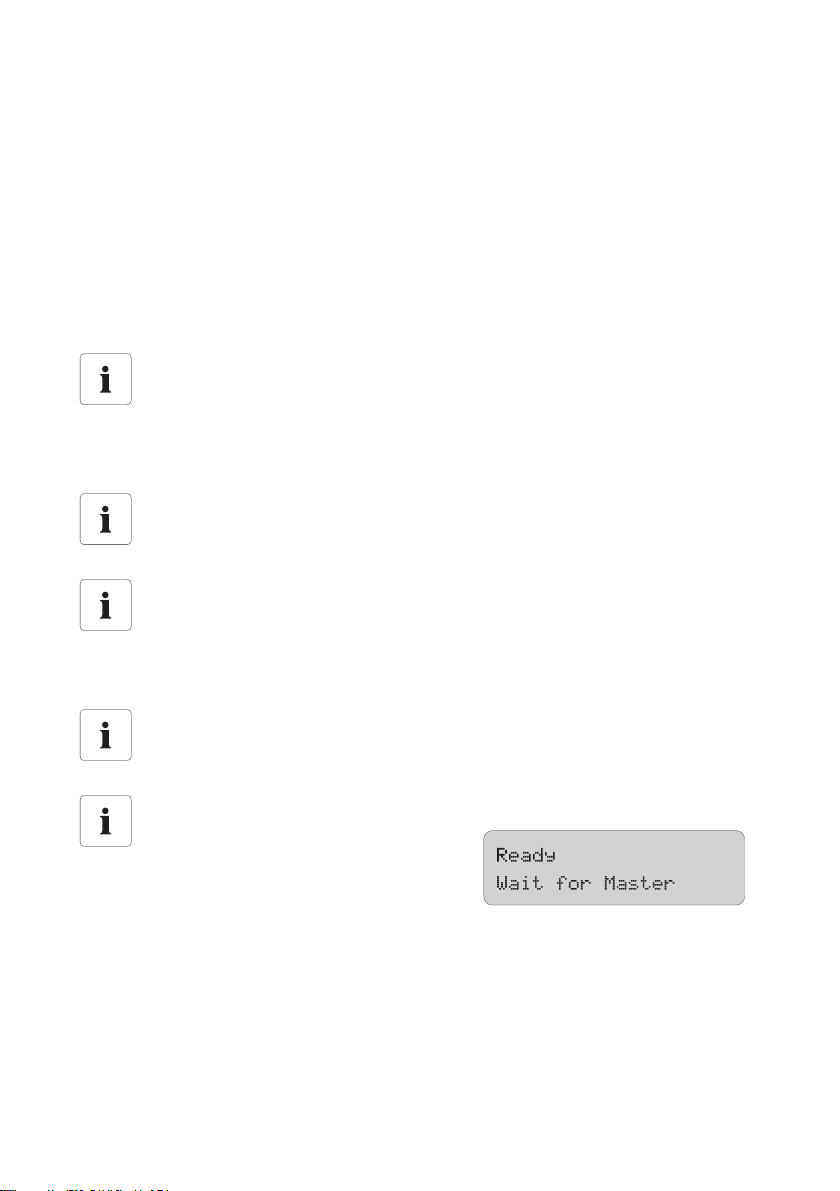
Operation SMA Solar Technology AG
10 Operation
The main menu consists of a "Home Screen" and the main menu entries, which split up into the different
menu levels. Operating modes are displayed on the Home Screen, e.g. the current operating mode,
performance, etc. See section 10.6”Display Messages (Overview)” (page74).
The menu consists of a main menu and maximum two submenu levels (see chapter 10.1”Menu
Structure” (page65)).
Use the up and down arrow buttons to navigate through the menu levels. The cyclical arrangement
(wrap around) allows you to scroll both forward and backwards to access the desired menu as
quickly as possible.
Fast access to menus
If you would like to access submenu 7, go backwards starting from 1 and continue past 9,
instead of going six steps forwards.
When the desired menu is reached press the <ENTER> key in order to activate it. The <ESC> key exits
the menu and puts you one menu level up.
Switching to the "home screen" after inactivity
If you do not press any buttons for more than five minutes (inactivity), the Home Screen is
automatically displayed.
Bacground lighting
The background illumination is automatically deactivated after a short time of inactivity.
You can switch the background illumination back on by pressing one of the four buttons.
No settings are changed when you press the button, this only activates the display
illumination.
Button sound
The button sound is switched on by default. To deactivate it, set the "250.04 BeepEna"
parameter to off.
Slaves wait for commands from the Master
Slave devices must wait for commands from
the master devices. The following message
appears on the display during this time.
The Sunny Island utilizes an operation concept referred to as "Single Point of Operation". For a
system with more than one device, all entries are made on the master. There you configure the entire
system, confirm events, warnings as well as errors in the QCG (see section 8”Initial Commissioning”
(page54)) and update your firmware when required (see section 11.6”Firmware Update”
(page86)).
Exception: When starting the device for the first time, you must set the slave devices as slave in the
QCG and everything else is performed at the master.
64 SI5048-TEN093630 Technical Description
Page 65
SMA Solar Technology AG Operation
Single Point of Operation
Single Point of Operation also means that all log data, including the slave log data, are
saved at the master device on the SD card.
Messages
Messages can be displayed at any time while the device is in operation and they have
priority over the "Home Screen" display.
10.1 Menu Structure
The navigation area includes the "Home Screen" and the following main menu items
• 100# Meters (display values)
• 200# Settings
• 300# Diagnosis
• 400# Failure/Event (lists)
• 500# Operation (operating functions)
• 600# Direct Access
The main menus are divided into several submenus.
In a submenu you can select a second submenu or a parameter.
NOTICE!
Incorrect parameters may cause system damage.
• Only qualified personnel are permitted to set and adjust system parameters.
You can access the navigation area from one of two levels:
•User level
• Installer level (password required)
The menu items and parameters which allow the changing of system parameters are accessible after
entering the installer password (see section 10.5”Entering the installer password” (page73)).
Technical Description SI5048-TEN093630 65
Page 66
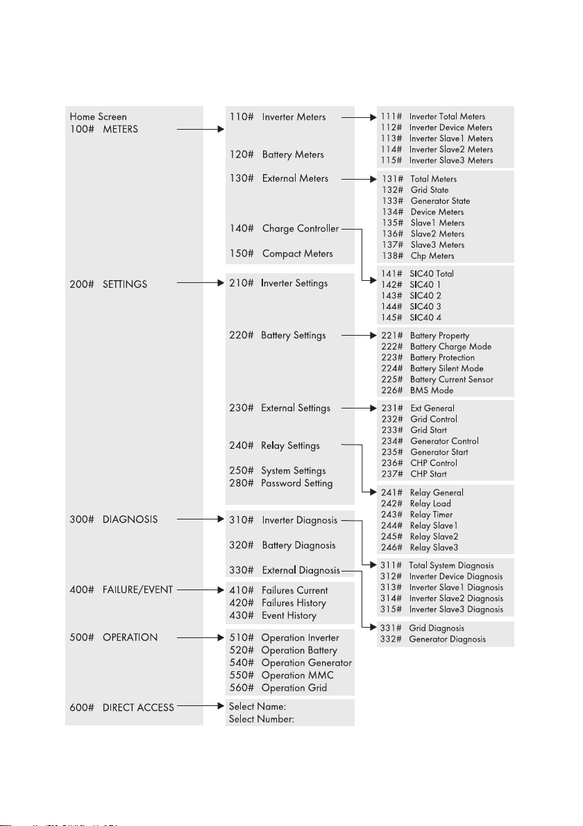
Operation SMA Solar Technology AG
Overview of the menu structure
66 SI5048-TEN093630 Technical Description
Page 67

SMA Solar Technology AG Operation
100# Meters - Display values:
This menu contains the display values for the following off-grid system components:
• 110# Meter Inverter - Sunny Island
• #120 Battery Meters - Battery
• 130# External meters - Grid/Generator
• 140# Charge Controller - Sunny Island Charger (is only shown when there is at least one
Sunny Island Charger connected to the Sunny Island)
• 150# Compact Meters - compact view of values for commissioning
By opening the relevant sub-menu - where appropriate, first the second sub-menu - you can view the
parameters (e.g., Parameter "112.03 InvVtg).
200# Settings
The following submenus allow you to view and adjust the system parameters:
• 210# Inverter Settings - Sunny Island
• 220# Battery Settings - Battery
• 230# External Settings - Grid/Generator
• 240# Relay Settings - Relays
• 250# System Settings - System
• 280# Password Setting - Passwort entry
300# Diagnosis
The following submenus allow you to view system data:
• 310# Inverter Diagnosis - Sunny Island
• 320# Battery Diagnosis - Battery
• 330# External Diagnosis - Grid/Generator
400# Failure/Event
The following submenus contain various error and event lists:
• 410# Failures Current - Current failures
• 420# Failure History - Previous warnings and errors
• 430# Event History - events
500# Operation - functions during operation
The following submenus allow you to view and adjust operating parameters:
• 510# Operation Inverter - Sunny Island
• 520# Operation Battery - Battery
• 540# Operation Generator - Generator
• 550# Operation MMC - SD card
• 560# Operation Grid - Grid
Technical Description SI5048-TEN093630 67
Page 68
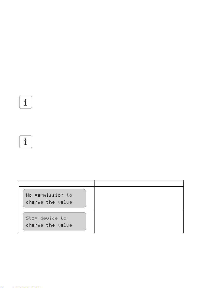
Operation SMA Solar Technology AG
600# Direct Access - Direct access to the parameters
This is a main menu that gives you direct accesss to the settings and display values (see section
10.3”Direct Access (to the parameters)” (page69)).
10.2 Changing Parameters
Using the up and down arrow buttons, you navigate through a selected menu to view or change a
parameter, for example. When the relevant parameter appears on the display, you can read its
present value.
An arrow next to the value indicates that the parameter can be changed.
If you press <ENTER>, the arrow begins to blink, and you can use the up and down arrow buttons to
change the value of the parameter.
Increment size (speed)
The increment size (speed) of the change increases if you hold the button pressed down.
As soon as the desired value appears on the display, press <ENTER> to save the new value.
Then select Y(es) or N(o) by pressing the up/down arrow buttons to accept or reject the changes.
Finally press <ENTER> again in order to finish the process and continue with other modifications.
Changing parameters
Note that some parameters can only be changed when the device is in standby mode
(see section 9.2”Stopping the Sunny Island (Standby)” (page61)). The parameters for
which this applies can be found in the tables in sections 19.2”Adjustable parameters”
(page147) and 20”Troubleshooting” (page184).
The Sunny Island displays a corresponding message for parameters that can only be changed in
standby mode or require a different password level.
Display Description
Incorrect password level, you cannot make any
changes in the menus. This is explained in section
10.5”Entering the installer password” (page73).
This parameter can only be changed in standby
mo de. St op the S unny Is land to change the parame ter
(see section 9.2”Stopping the Sunny Island
(Standby)” (page61)).
68 SI5048-TEN093630 Technical Description
Page 69
SMA Solar Technology AG Operation
10.3 Direct Access (to the parameters)
The "600# Direct Access" menu gives you direct access to the selected parameter using the
parameter name or number.
Via the Select Name submenu, you have direct access to the following functions:
•GnManStr: manual starting of the generator (see section 14.1.4”Manual Generator
Operation” (page107)).
• ManChargSel: manual starting of equalization charge (see section 13.4.3”Equalization
Charge” (page97)).
Via the Select Number menu, you have direct access to every parameter by entering the parameter
number.
Example
Using the menu 600# Direct Access, you can select the "222.01 BatChrgCurMax"
parameter, for example, to set the maximum battery charging current.
The direct access must be entered as a five-digit number, for example, 22201. Here, the
first three digits describe the menu number and the last two describe the parameter number.
Exit the menu level after the parameter has been set.
10.4 Compact Meters
The "150# Compact Meters" menu is primarily intended to help the installer commission the device.
The display gives you information at a glance on the following areas:
•Battery 1
•Battery 2
• Inverter (AC values)
•InvTot
• Grid/generator (external)
•ExtTot
•Inverter status
Selecting the area
You can select the different displays of the compact meters using the up/down arrow keys.
Here, you can also use the "Wrap Around" function.
The displays are always shown from the upper left to the lower right.
Technical Description SI5048-TEN093630 69
Page 70
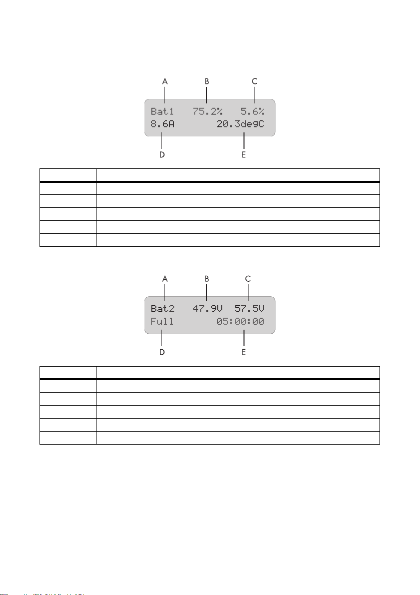
Operation SMA Solar Technology AG
Bat 1 (Battery Value 1)
Position Description
A Name of the Compact Meters
B Present battery charge state (BatSoc)
C Estimated error of the charge state (BatSocErr)
D Total battery current of the cluster (TotBatCur)
E Battery temperature (BatTmp)
Bat 2 (Battery Value 2)
Position Description
A Name of the Compact Meters
B Battery voltage (BatVtg)
C Nominal value of charging voltage (BatChrgVtg)
D Active charging process (BatChrgOp)
E Remaining absorption time (AptTmRmg)
70 SI5048-TEN093630 Technical Description
Page 71
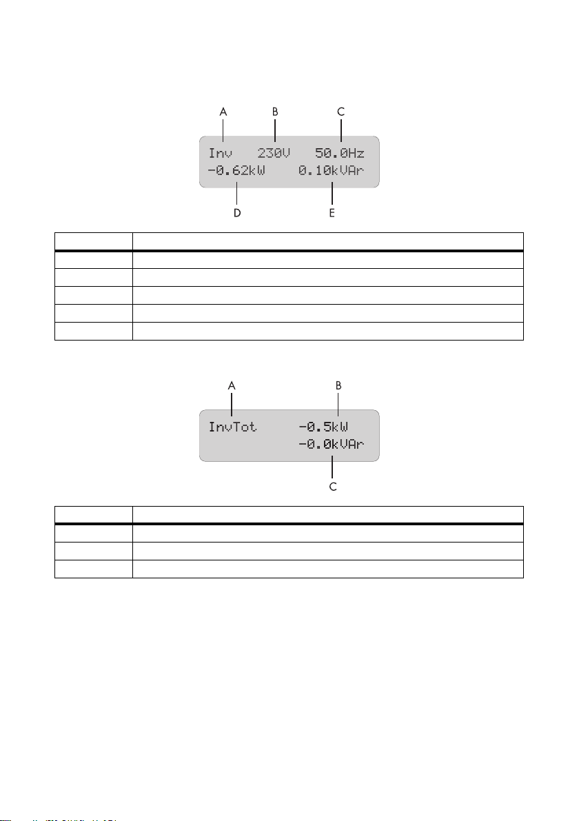
SMA Solar Technology AG Operation
Inv (AC Values of Inverter)
Position Description
A Name of the Compact Meters
B Present voltage at the inverter (InvVtg)
C Present frequency at the inverter (InvFrq)
D Present active power of the inverter (InvPwrAt)
E Present reactive power at the inverter (InvPwrPt)
InvTot (Total AC Values of Inverter)
Position Description
A Name of the Compact Meters
BTotal active power of the inverter (cluster)
C Total reactive power of the inverter (cluster)
Technical Description SI5048-TEN093630 71
Page 72
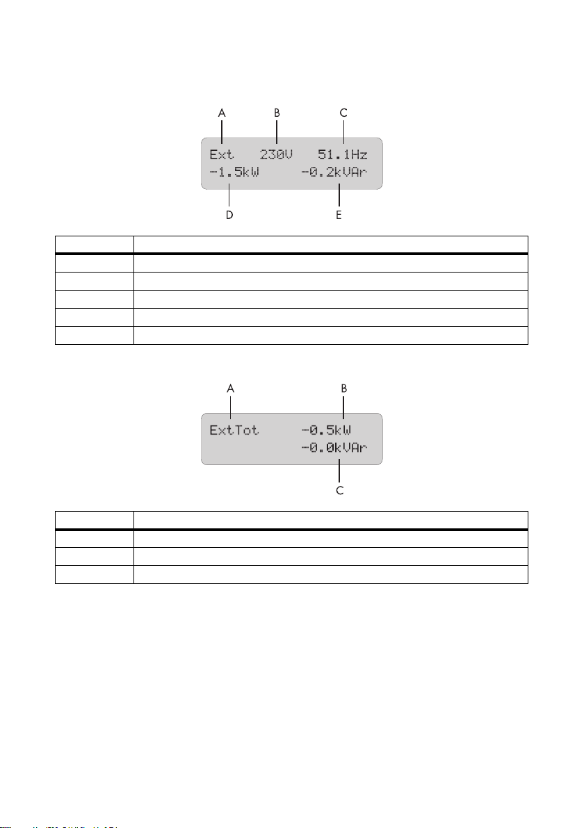
Operation SMA Solar Technology AG
Ext (AC values of external source)
Position Description
A Name of the Compact Meters
B Voltage of the external source (ExtVtg)
C Frecuency of the external source (ExtFrq)
D Active power of the external source (ExtPwrAt)
E Reactive power of the external source (ExtPwrPt)
ExtTot (Total AC Values of External Source)
Position Description
A Name of the Compact Meters
B Total active power of the external source (cluster)
C Total reactive power of the external source (cluster)
72 SI5048-TEN093630 Technical Description
Page 73
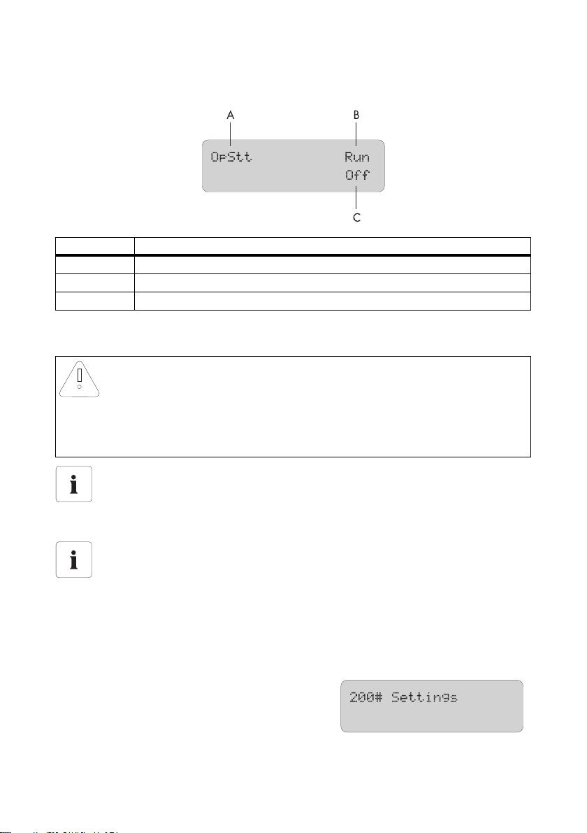
SMA Solar Technology AG Operation
OpStt (Inverter and Generator Status)
Position Description
A Name of the Compact Meters
B Operating state of the inverter (InvOpStt)
C State of the generator (GnStt)
10.5 Entering the installer password
NOTICE!
Incorrect parameters may cause system damage.
All parameter settings which could affect the operating safety of the off-grid system are
protected/locked by the installer password.
• Only qualified personnel are permitted to set and adjust system parameters.
Do not disclose the password to unauthorized persons
Do not provide the following information for entering the installer password to
unauthorized persons. Illegal provision of this information to other persons will lead to
invalidation of all warranties by SMA Solar Technology.
Entering the Password
The Sunny Island allows you to enter the password not only in standby, but also during
operation.
The password is dependent on the operating hours counter. In the installer level there are extended
access privileges to all necessary parameters.
Password = Sum of digits of the operating hours
Proceed as follows to enter the installer password from the "Home Screen":
1. Keep pressing the down arrow button until you
reach the menu "200# Settings".
2. Press <ENTER>.
Technical Description SI5048-TEN093630 73
Page 74
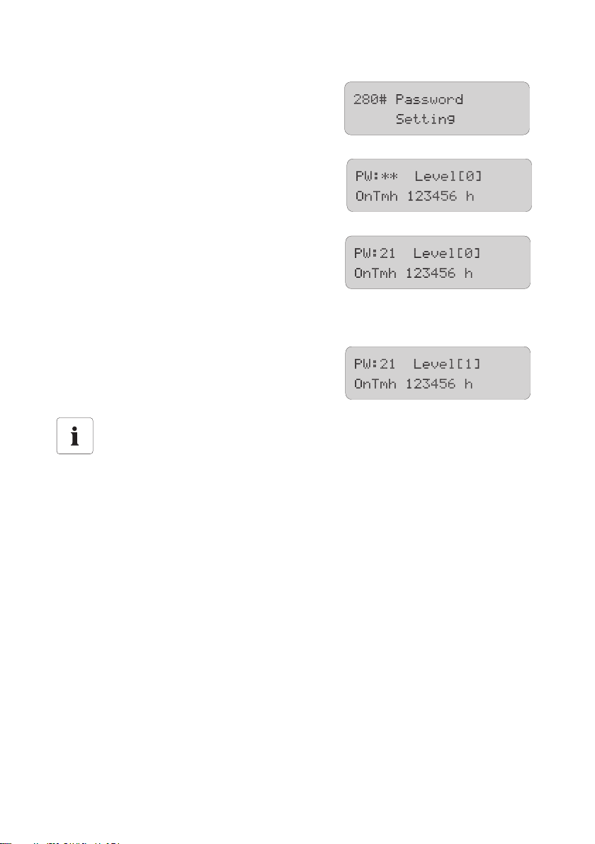
Operation SMA Solar Technology AG
3. Keep pressing the down arrow button until you
reach the menu "280# Password Setting".
4. Press <ENTER>.
☑ The submenu for "280# Password Setting"
opens.
5. Press <ENTER>.
6. Dete rmi nin g th e passw ord . Calcu lat e th e sum of the
digits of the operating hours. In the message shown
here:
1 + 2 + 3 + 4 + 5 + 6 = 21
7. You can enter the password by pressing the up/down arrow buttons.
8. Confirm the password by pressing <ENTER>.
☑ The installer password has been entered.
Operating level [1] = the installer level is set.
9. Exit the menu by pressing the <ESC> key.
Switching operating levels
If the password is invalid, the Sunny Island does not switch to the installer level. In this case,
recalculate and re-enter the installer password as described in this section.
The installer level is switched back to the user level if:
• the Sunny Island is switched off and on again.
• specific parameters are entered (e.g., the "510.01 InvRs" parameter) that cause a
restart.
• an incorrect password is entered.
• if no activity takes place within five minutes.
10.6 Display Messages (Overview)
The display has two lines, each with 16 characters. The first line shows the menu number and the menu
na me, or t he n ame of t he p ara met er w her e ap pli cab le. The men u name is supplemented or the added
text is displayed (e.g., parameter value) in the lower line, if required.
74 SI5048-TEN093630 Technical Description
Page 75
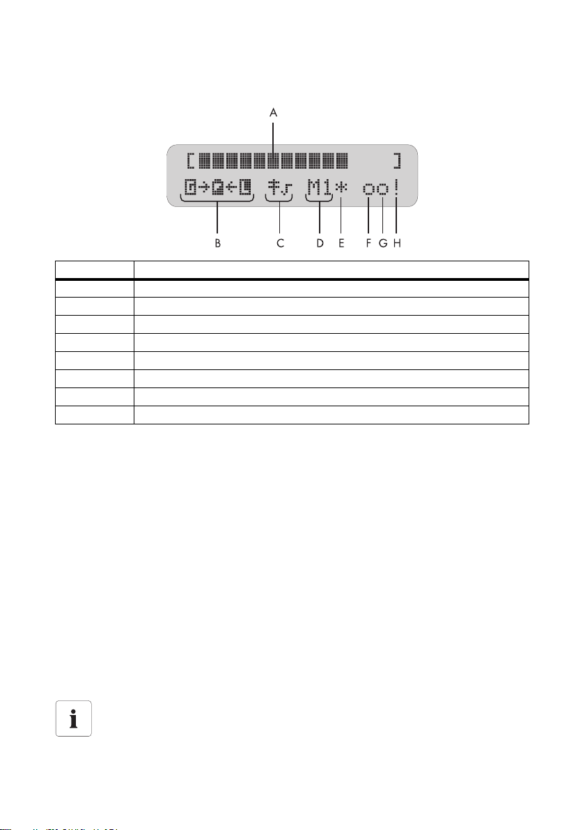
SMA Solar Technology AG Operation
"Home Screen"
Position Description
A Output power/charging power (load status)
B Direction of energy flow and system status
CGrid status
D Device assignment
E Status of the external source (star, question mark or exclamation mark)
FRelay 1 status
G Relay 2 status
H Warning message (exclamation mark)
In the Home Screen, the Sunny Island also shows the following values in succession
(in 3-second intervals: parameter name and parameter value) in the upper line:
• Bar graph for output power or charging power (the direction of energy flow is displayed by the
arrows in the lower line)
• Total active power of the inverter (cluster)
• Active power of external source (total of all phases)
• Present state of charge of the battery (SOC)
• Counters (always one of five possibilities, depending on priority)
– remaining absorption time
– remaining generator warm up time
– Remaining Run1h time for the generator
– remaining time of Timer 1
– remaining time of Timer 2
• Active charging process
Situation-Dependent Value Display
The values shown on the display are displayed or not depending on the situation. That is,
if there is no generator connected, no generator values are shown on the display.
Technical Description SI5048-TEN093630 75
Page 76
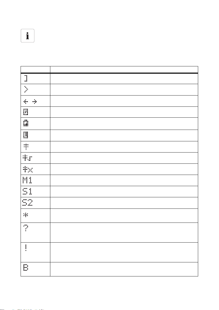
Operation SMA Solar Technology AG
Messages on the slave Devices
On the slave devices, only the bar graph is displayed for output power or charging power
and in the lower line, the device assignment (e.g., S1 for slave1) and where applicable,
the status of external sources (*, for a description, please see further above) are displayed.
Meaning of the symbols appearing on the "Home Screen"
Symbol Purpose
Nominal power
Nominal load exceeded.
Direction of energy flow between grid/generator side, battery and load side.
Generator/grid side is on
Battery
Load side (loads/Sunny Boys)
Power pole
Public grid is connected. The Sunny Island is working with grid limits.
The generator is now connected. The Sunny Island is working with generator limits.
The Sunny Island is configured as master.
The Sunny Island is configured as slave 1.
The Sunny Island is configured as slave 2.
Status of the external source:
Voltage and frequency of the generator/grid are within set limits.
Status of the external source:
Voltage and frequency of the generator/grid are within set limits. In this case,
the Sunny Island does not connect the generator to the island grid.
Status of the external source:
The maximal admissible generator reverse power was exceeded, the Sunny Island
has disconnected the generator from the stand-alone grid.
Requirement reason "Battery":
The generator has been requested as a result of the battery charge level.
76 SI5048-TEN093630 Technical Description
Page 77
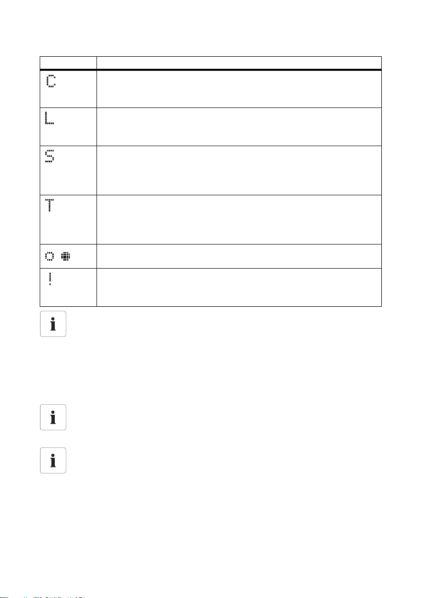
SMA Solar Technology AG Operation
Symbol Purpose
Request reason "Cycle":
The generator was requested via the generator operation's time-dependent
repetition cycle.
Requirement reason "Load":
The generator has been requested as a result of the load-dependent generator
request.
Requirement reason "Start":
The generator has been requested by the operator manually setting the generator
request in the Sunny Island from "Auto" to "Start". The generator is then no longer
automatically controlled or switched off by the Sunny Island.
Requirement reason "Time":
The generator was started for one hour using the "Run1h" setting in the
Sunny Island. Once this time has passed, the Sunny Island automatically switches
off the generator.
Display for relays (solid circle = the relay is activated / empty circle = the relay is
deactivated).
Warning message:
This symbol blinks until you have viewed the warning in the menu
"410# Failures Current" or "420# Failure History".
Display "Generator Status" and "Request Reason"
Both indications mentioned above appear alternatively on the display as status of the
external source.
Example:
If, for example, the display changes every 3 seconds from "*" to "B", this means that the
generator voltage and frequency lie within the specified limits and that the generator was
requested as a result of the battery charge level.
Stopping the Generator Manually
If the generator has been manually set to "Stop", then no generator status information is
shown on the display. The field remains empty in this case.
Indications of a Warning
If faults occur, the device switches into standby mode and shows the fault on the display.
The fault must be eliminated and confirmed, then the Sunny Island carries out an autostart.
Technical Description SI5048-TEN093630 77
Page 78
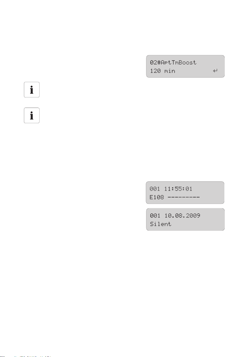
Operation SMA Solar Technology AG
10.7 Parameter Display
Parameters on the Sunny Island are displayed as follows:
In the upper line, the parameter number comes first, then
a separator (hash) followed by the parameter name.
In the lower line, there is the value with the unit and the
modification mark (enter arrow) is on the far right.
Parameter/Value List
If you would like to switch from a menu (regardless of whether it is a main or submenu) into
a parameter/value list, the menu numbers are not included on the display.
Notation for Menus and Parameters
The syntax specified here for menus and parameters apply to the entire document.
A menu is identified by the number of the menu, the hash and the name of the menu
(e.g., 120# Battery Meters).
A parameter is identified by the menu number, period, parameter number and the name of
the parameter (120.02 BatVtg).
10.8 Display of Events
The Sunny Island can display a list of events:
The serial number (quantity) of the events, the time and
date display, which changes in 2-second intervals, is in
the upper line. In the lower line are the number of the
event and the corresponding short text.
78 SI5048-TEN093630 Technical Description
Page 79
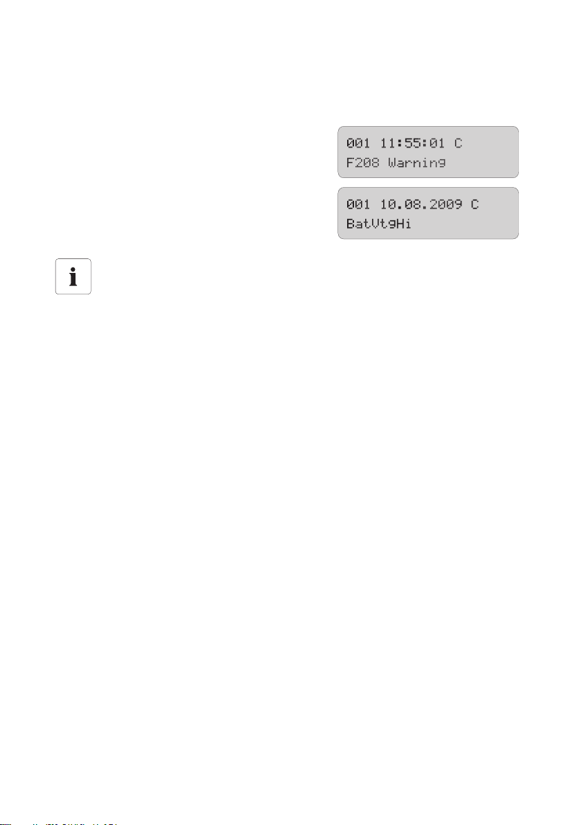
SMA Solar Technology AG Operation
10.9 Display of Warnings and Failures
The Sunny Island can display a list of errors and warnings:
The running number (quantity) of the errors is on the
upper line; the time and date display changes in
2-second intervals. In the lower line are the number of the
error and the corresponding error short text.
A "!" on the right in the upper line indicates when the
warning and/or error occurred.
A "C" on the right in the upper line indicates when the
warning or the error was confirmed or cleared.
Direct Access to the Error List
As a sh ort cut , pr ess "ES C and th e ar row up b utt on" sim ult ane ous ly t o go dir ect ly t o th e er ror
list (420# Failure History).
Technical Description SI5048-TEN093630 79
Page 80
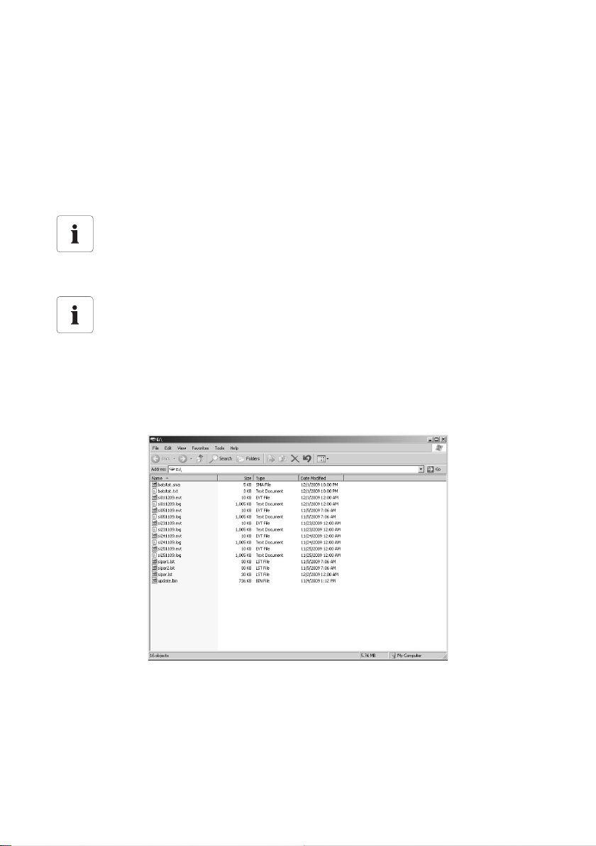
Archiving Data on an SD Card SMA Solar Technology AG
11 Archiving Data on an SD Card
The Sunny Island can save firmware, parameters and measuring data on a multimedia card
(MMC/SD card) that must be FAT-16-formatted and may have a maximum capacity of 2 GB
(possible memory capacities are 32/64/128/256/512 MB as well as 1 GB and 2 GB). Use the
SD card included in delivery solely for the Sunny Island. Do not save any multimedia data on the SD
card.
File names are saved in 8.3 format and files with other designations are ignored.
Format example
A valid 8.3 format is, for example, "M1111LOG.DAT".
8.3 is the "old" MS-DOS format with a file name that has a maximum of 8 figures before
and 3 figures after the dot.
Type of Memory Card
SMA Solar Technology recommends using MMC/SD cards manufactured by Transcend.
If you use a memory card from another manufacturer, check whether the card is
FAT16-formatted. If necessary, format the card. Be aware that data stored on the card will
be lost.
After you have inserted the SD card into the card reader slot on your PC, you can search for the
respective drive in the Explorer (in Microsoft Windows). The following data are on this drive (here E:):
80 SI5048-TEN093630 Technical Description
Page 81
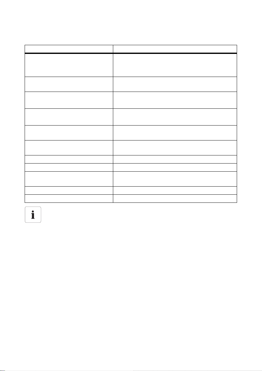
SMA Solar Technology AG Archiving Data on an SD Card
The files on the SD card have the following meanings:
File name Purpose
evthism.log (evthisN.log for slaveN) Event history of the device, saved by means of parameter
"550.03 CardFunc",
option StoEvtHis
failhism.log (failhisN.log for slaveN) Failure history of the device, saved by means of
parameter "550.03 CardFunc", option StoFailHis
si030607.evt Event/failure history for the day
(format: ddmmyy)
si030607.log Data recording for the day
(format: ddmmyy)
sipar1.lst parameter list of the device, created by means of
parameter "550.01 ParaSto", option Set1
sipar2.lst parameter list of the device, created by means of
parameter "550.01 ParaSto", option Set2
sipar.lst This file is saved after changing a parameter.
update.bin Software for the device
batstat.txt Statistical values of the battery. These values are saved
every day at 22:00 hours.
batstat.sma Internal data from SMA Solar Technology
si.ccf System information from Sunny Island
"BOOTEX.LOG" File
The "BOOTEX.LOG" file is not necessarily on the card. It is created depending on the
operating system used (e.g. WindowsXP or Windows2000).
The Sunny Island's firmware expects device-specific data in the main directory of the SD card.
This data includes a new firmware, parameters and measuring data.
The Sunny Island uses the SD card for saving and loading device parameters.
In addition, the Sunny Island supports the acquisition of measurement data on the SD card. It saves
th is d ata in a spe cia l fi le. Thi s con tai ns, amo ng o ther thi ngs , a header, time stamp, date and data type.
There are two different types of log data:
• Measurement data (is saved cyclically)
• Events and errors (are only saved when they occur)
The Sunny Island supports the acquisition of measurement data with data from the fields:
•Battery
•Inverter
•System
•External source
•Loads
Technical Description SI5048-TEN093630 81
Page 82
Archiving Data on an SD Card SMA Solar Technology AG
Always save data
Always use the SD card to save data and events. In case of a failure SMA Solar
Technology can thus quickly help you.
The data saved on the SD card can be processed using common table calculation programs.
• The first 14 lines of the file are used for information (file header).
• The data following this are separated by semicolons.
• Decimal places are separated by periods.
• The date format is dd.mm.yyyy.
• The time format is hh:mm.
Log data
For additional information on processing the log data, please refer to the manual of the
data processing software you use.
82 SI5048-TEN093630 Technical Description
Page 83
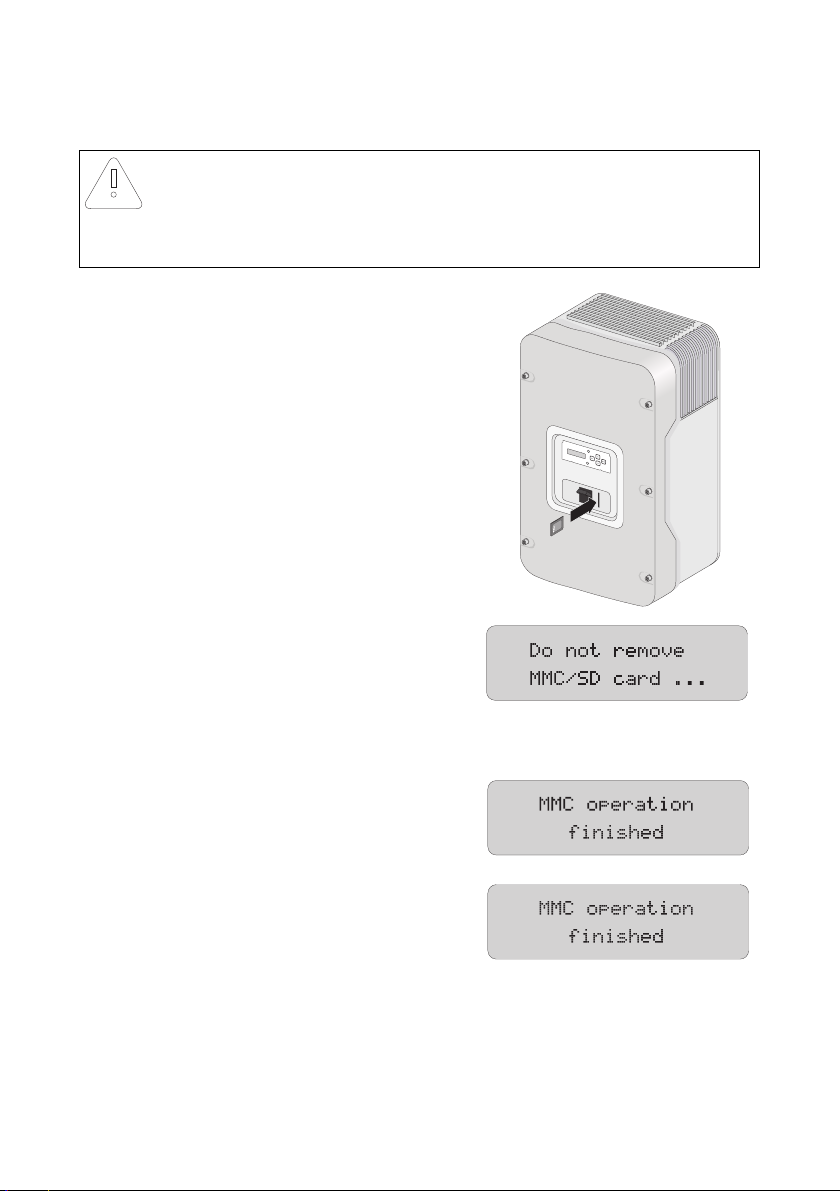
SMA Solar Technology AG Archiving Data on an SD Card
11.1 Inserting the Card
NOTICE!
Damage due to electrostatic discharges.
• Ground yourself before you insert or remove the SD card from the Sunny Island
housing.
Insert the SD card with the cut corner pointing down into
the slot on the Sunny Island (see illustration).
After inserting the SD card into the Sunny Island, the
message shown appears on the display, prohibiting the
removal of the card.
The initialization of the SD card can take several minutes. During this time, the buttons are disabled
and cannot be used for making entries, and three points appear in the lower line of the display.
If the procedure was successful, the graphic shown here
is shown.
In case of a fault, the following message appears:
Technical Description SI5048-TEN093630 83
Page 84
Archiving Data on an SD Card SMA Solar Technology AG
11.2 Removing the Card
To ensure that all log data is saved upon deactivation, write all as-yet unsaved data from the buffer
to the SD-Card by using the parameter "550.03 CardFunc" with the option "ForcedWrite".
Data loss
If you remove the SD card without first activating the parameter "550.03 CardFunc",
you lose up to a maximum of 15 minutes' data.
11.3 Saving and Loading Parameters
Using the "510.02 ParaSto" parameter, you can save the current parameter settings and using the
"510.02 ParaLod" parameter, you can load the saved parameters.
Save Settings
If the system is working optimally, it is a good idea to save these settings. This is especially
useful if you try out new settings and then wish to reset the inverter back to the previous
settings.
When saving the parameters you have the following options:
• Set1 (save parameter set 1)
• Set2 (save parameter set 2)
When loading the parameters you have the following options:
• Set1 (load parameter set 1)
• Set2 (load parameter set 2)
• Factory (load the factory settings (reset))
Write Protection Function of SD Cards
The write protect function of SD cards (plastic sliding clip on the left side) is not supported
by the Sunny Island. You should take note of this when writing data to your card.
11.4 Writing Log Data
Using the "550.04 DatLogEna" parameter, you can activate the function for writing log data to your
SD-Card (activated by default).
If the Sunny Island is writing data to the SD card,
removing the card is prohibited and the message shown
here appears on the display.
84 SI5048-TEN093630 Technical Description
Page 85
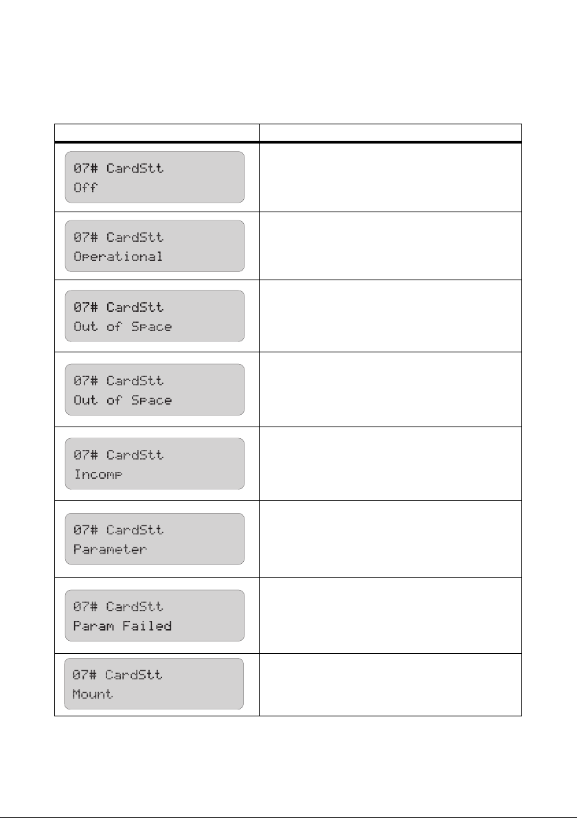
SMA Solar Technology AG Archiving Data on an SD Card
11.5 Status Messages
Using the "312.07 CardStt" parameter, you can request the status of your SD card:
Display Description
The SD card is deactivated.
The SD card is activated.
The memory capacity of your SD card has been
exceeded.
The SD card has an invalid file format.
The SD card is not compatible.
Your Sunny Island is loading parameters from the SD
card.
Loading parameters from SD card has failed.
The SD card is being accessed.
Technical Description SI5048-TEN093630 85
Page 86
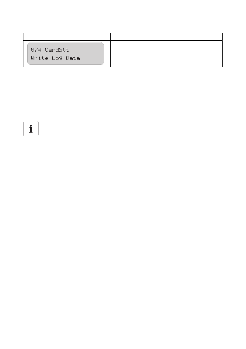
Archiving Data on an SD Card SMA Solar Technology AG
Display Description
The Sunny Island is writing log data onto the SD card.
11.6 Firmware Update
The firmware of the Sunny Island can be updated using the SD card. When the Sunny Island starts up
or when the SD card is inserted, the Sunny Island searches for special update files on the SD card.
If it finds files containing new firmware versions, it performs an update when the Sunny Island is in
standby mode.
Proceed as follows for a firmware update:
Note:
• You may only download firmware versions from www.SMA.de/en. Using
unauthorized firmware versions cancels the warranty.
• None of the already-existing parameter settings are changed or erased during a
firmware update.
• New parameters are set with default values.
• If there is an update to firmware version greater or equal to 5.000 the battery
management is automatically reset. All set parameters are lost.
• Do not activate the DC circuit breaker during the firmware update.
• Do not switch off the Sunny Island during the firmware update.
1. Create a security copy of the existing parameter lists (see chapter 11.3”Saving and Loading
Parameters” (page84)).
2. Download the current version of the firmware from the Internet at www.SMA.de/en.
3. Copy the "UPDATE.BIN" file onto the SD card.
4. Set the master device to standby.
5. Insert the SD card in the master's slot.
86 SI5048-TEN093630 Technical Description
Page 87
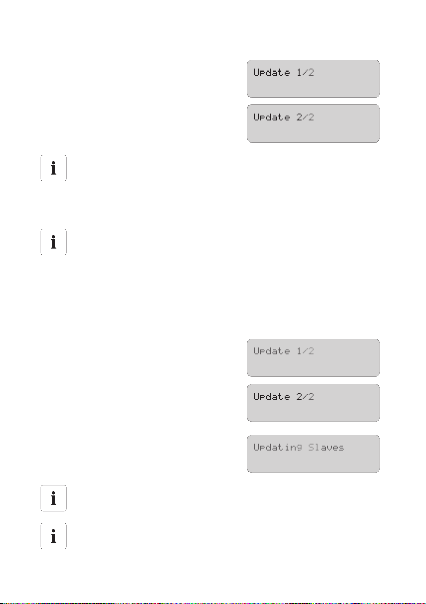
SMA Solar Technology AG Archiving Data on an SD Card
☑ T he upda te is ca rried o ut. Dur ing the upd ate, th e
message shown here is displayed.
Reset after a successful update
After the update has been successfully completed a reset is enforced in order that the
changes become effective. After the reset, the master device remains in standby mode.
6. Presss <ENTER> and hold.
☑ The Sunny is started. The update has been carried out.
Starting QCG
If you have carried out a firmware update in which the number before the period in the
firmware version has changed, it is advisable to start QCG and to perform all settings
anew.
Firmware Update in a System with Several Sunny Islands
In a sy ste m wi th seve ral Sun ny I sla nd devi ces , th e firmw are is o nly upd ate d on the mas ter . If the mas ter
detects that a slave has a different firmware version, it transmits its firmware to the slave and makes
sure that all Sunny Island devices within a system operate with the identical firmware version.
While the master updates the slave(s), the slave(s)
display(s) the message shown here.
At the same time, the message shown here appears on
the master.
After the firmware update, the parameters are
downloaded onto the slave devices.
Wait until all slave processes have terminated, and until
this display appears on the slave devices' screens.
Parameters and Settings
Individual parameters and settings are retained during a firmware update.
Switching on a slave with a different firmware version
If a slave with a different firmware version is switched on, the master interrupts operation,
performs a cluster update and starts up together with the slaves.
Technical Description SI5048-TEN093630 87
Page 88
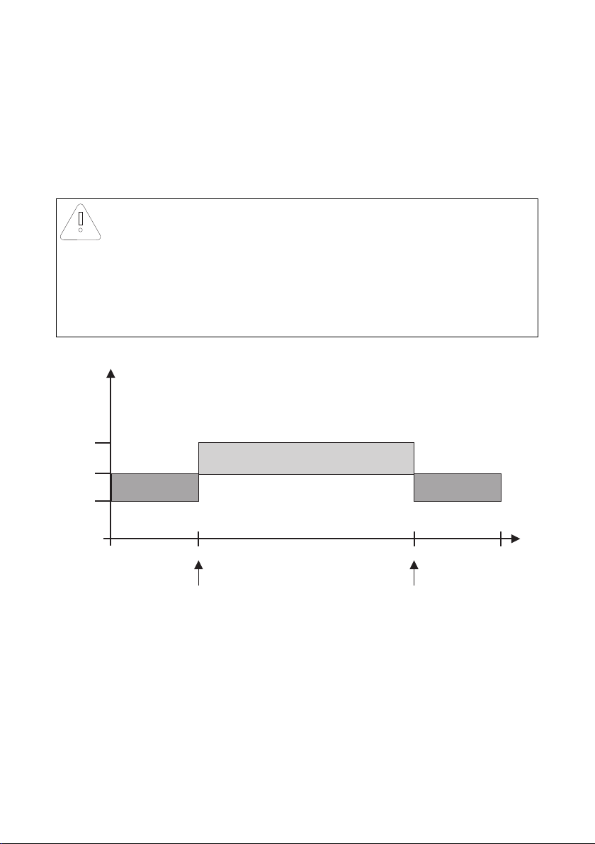
Additional Functions SMA Solar Technology AG
Lod1SocTm2 Stp Lod1SocTm2 Stp
0h 6h
Lod1Tm1Str Lod1Tm2Str
Lod1SocTm1 Stp
22h 24h
Lod1SocTm2 Str Lod1SocTm2 Str
Lod1SocTm1 Str
t1
t2
t2
30
40
80
Soc [%]
12 Additional Functions
12.1 Load Shedding
The Sunny Island can automatically switch off loads to protect the batteries from deep discharge. To
do this, an external (AC or DC) power contactor must be installed between the Sunny Island and the
loads (see also section 21”Accessories” (page204)).
NOTICE!
Faulty system operation due to lack of load shedding.
• Install external load-shedding protection in case the off-grid system on the
AC-generating side is coupled to PV generators or wind generators.
• If there is overloading due to low energy production or very high energy
consumption, you must be able to switch off loads.
• Always switch off the loads, never the energy generators (e.g., Sunny Boy)!
The graphic shows an example for the settings that minimize the load shedding function at night.
From 6:00 a.m. to 22:00 p.m. the load shedding is activated for a charge state (SOC) of 40 %,
du rin g ni ght tim e (f rom 22: 00 p .m. to 6:00 a.m .), by c ont ras t, t he charge state of the battery is allowed
to go down to 30 % before the load-shedding contactor is activated.
The load shedding function can be assigned twice. In the parameters mentioned above, the "Lod1"
part represents the first assigned function and the "Lod2" part represents a second, identical function.
These two load shedding functions, which are dependent on the battery's state of charge, allow for
tiered load shedding in which, by using different SOC values, different priorities can be given to
various load groups.
88 SI5048-TEN093630 Technical Description
Page 89
SMA Solar Technology AG Additional Functions
Define the time intervals t1 and t2:
• Starting time t1: with the parameter "242.05 Lod1Tm1Str", set the start time for t1
(and with it the end of t2).
• Starting time t2: with the parameter "242.06 Lod1Tm2Str", set the start time for t2
(and with it the end of t1).
• If the time intervals t1 (Lod1Tm1Str) and t2 (Lod1Tm2Str) are consistent with one another,
only t1 will be activated.
Set the battery state of charge at which the time interval t1 or t2 will start/stop:
• The battery state of charge during the t1 interval, the recognition of which will lead to the
load-shedding function being started: Parameter "242.01 Lod1SocTm1Str"
• The battery state of charge during the t1 interval, the recognition of which will lead to the
load-shedding function being stopped: Parameter "242.02 Lod1SocTm1Stp"
• The battery state of charge during the t2 interval, the recognition of which will lead to the
load-shedding function being started: Parameter "242.03 Lod1SocTm2Str"
• The battery state of charge during the t2 interval, the recognition of which will lead to the
load-shedding function being stopped: Parameter "242.04 Lod1SocTm2Stp"
12.2 Sleep Mode
Using the "250.10 SleepEna" parameter set to "Enable" allows the sleep mode to be activated in
single-phase grids, which the master uses to switch off the slaves when the power value allows this.
Sleep Mode
The "Sleep Mode" works exclusively in stand-alone grid operation! The values for
connection and disconnection of the Sunny Island are already set at the factory
(optimized in terms of efficiency).
12.3 Time-Controlled Operation
The Sunny Island can be operated in a time-controlled fashion using a timer function (like a clock
timer), supplying power at a planned point in time.
To do this, this function must be activated by using the "510.02 InvTmOpEna" parameter. With the
"510.03 InvTmOpStrDt" parameter you can specify the starting date, and with the "510.04
InvTmStrTm" you specify the starting time. With the parameter "510.05 InvTmOpRnDur" you set the
running time and with the parameter "510.06 InvTmOpCyc" you determine whether this function will
be carried out once, or every day or week, at or for the first time at the specified start time
(date and time).
Technical Description SI5048-TEN093630 89
Page 90
Additional Functions SMA Solar Technology AG
12.4 Overload and Short-Circuit Behavior
The Sunny Island can be temporarily operated under overload conditions. It can also supply shortcircuit currents.
In case of overload, the Sunny Island supplies an output of 6500 W for 30 minutes and can supply
7200 W for 5 minutes. The device can even supply 8400 W of output power for one minute.
If a short circuit occurs, the Sunny Island provides current of max. 100 A (for 100ms). This is sufficient
to trigger commercial 16 A B-type circuit breakers.
12.5 Device Faults and Autostart
If a critical fault occurs, the Sunny Island automatically shuts down and displays the reason on the
display. If the autostart function is activated ("250.01 AutoStr" parameter) the Sunny Island can
confirm the failure automatically and restart on its own. If the failure persists the Sunny Island cannot
be started.
Automatic Start Counter
If the autostart counter has counted down to 0, the Sunny Island waits for 10 minutes
before attempting to restart automatically.
Display of messages
Messages can be displayed at any time while the device is in operation and they have
priority over the Home Screen display.
12.6 Automatic Frequency Adjustment (AFRA)
Clocks that depend on the stability of the grid frequency for their accuracy become increasingly
inaccurate when there are constant frequency deviations. Frequ ency fluctuations, i.e., deviations from
the nominal frequency occur, for example, in stand-alone grid systems that operate with a diesel
generator.
The "Automatic Frequency Adjustment (AFRA)" function of the Sunny Island (also referred to as tertiary
control) allows the use of grid-coupled clocks in these types of stand-alone systems. This function is
activated using the "250.11 TertCtlEna" parameter (activated by default).
The time deviation is compensated on average.
Quartz Clock in the Sunny Island
The internal clock in the Sunny Island is quartz-controlled and thus operates correctly
(within the tolerance limits). The adjustment refers to externally connected clocks that
depend on the grid frequency.
90 SI5048-TEN093630 Technical Description
Page 91

SMA Solar Technology AG Additional Functions
12.7 Time-Controlled Standby
You can set the Sunny Island to standby mode in a time-controlled way. Activate the time-controlled
standby using the parameter "250.13 SlpAtNgt". Set the parameter to "Disable".
After activation set the start and stop times for the Sunny Boy. Carry out the setting via the parameter
"250.14 SlpStrTm" and "250.15 SlpStpTm".
12.8 Reaction in case of failures
Using the parameter "250.30 RnMod" you can influence the behavior of the Sunny Island in a
three-phase system in case of a fault. The parameter is set to "RunAlways" at the factory. This means
that the Sunny Island master ignores all faults at the slave devices.
If you set the parameter to "StopAlways" the system will be put in standby mode upon detection of a
fault at the slave devices. Faults which can be removed via an autostart are not included.
Technical Description SI5048-TEN093630 91
Page 92
Battery management SMA Solar Technology AG
13 Battery management
The battery management of the Sunny Island supports the following three battery types
("221.01 BatTyp" parameter):
•FLA
•VRLA
•NiCd
The battery capacity ("221.02 BatCpyNom" parameter) is to be entered as the nominal capacity for
a ten-hour discharge (C10). If this information is not available from the battery manufacturer's data
sheet, it can be calculated from the data for different discharge times (120 h, 100 h, 20 h, 5 h, 1 h)
in the following manner:
C10 C120/1.28 C10 C10
C10 C100/1.25 C10 C5/0.88
C10 C20/1.09 C10 C1/0.61
The Sunny Island is designed and set by default (parameter "221.03 BatVtgNom") for a nominal
battery voltage:
• 48 V (24 cells at 2 V each) in the case of lead batteries (FLA and VRLA)
• 45.6 V (38 cells at 1.2 V each) in the case of Nickel-Cadmium batteries
Malfunction of individual battery cells
If individual battery cells fail over several years of continuous operation, the nominal
voltage can be set in the range from 42 V to 48 V. Up to three individual cells can be
removed and the system can still be further operated.
13.1 Battery temperature
The Sunny Island continuously monitors the battery temperature using the battery temperature sensor
provided. At 5°C under the maximal temperature allowed (set using the parameter "221.04
BatTmpMax"), a warning is displayed. If the maximal value for the battery temperature is exceeded,
the Sunny Island switches off.
When lead acid batteries drop below − 10 °C and NiCd batteries drop below − 20 °C, a warning
is displayed.
The battery temperature is taken into consideration when the charging voltage is calculated
(see section 13.4”Charge control” (page94)).
92 SI5048-TEN093630 Technical Description
Page 93
SMA Solar Technology AG Battery management
NOTICE!
Possible damage to the battery as a result of faulty temperature measurement.
If the battery temperature sensor is defective or missing, the Sunny Island continues to run,
assuming a battery temperature of 40 °C. This can result in insufficient charging of the
battery in the long run.
• Observe the corresponding warnings of the Sunny Island.
• Connect the battery temperature sensor.
• Replace the defective battery temperature sensor.
13.2 Start Options
If the battery is replaced in a system, the battery management system must be restarted and
reconfigured. This can be done using the "Quick Configuration Guide QCG" (see section
8.2”Starting the Quick Configuration Guide (QCG)” (page55)).
13.3 State of Charge / SOC and SOH
The Sunny Island has a very precise internal charge level calculation (display value
"120.01 BatSoc"). The operation for calculating the charge level is based on balancing the ampere
hours. This means that all currents flowing in and out of the battery are accumulated and referred to
the nominal capacity. In order to take into consideration faults caused by self discharge and charging
losses caused by gassing, these losses are already internally extracted. Unlike other operations, no
fixed charging factor must be set.
After full charge has been reached, the charge state value is reset to 90 %, 95 % or 100 %,
depending on the actual state of charge of the battery. If default settings are not changed, a state of
charge of 90 % after boost charge, 95 % after full charge and 100 % after equalization charge is
reached.
Since fully charged states are only rarely achieved, the operation used here can also use the battery
voltage during constant discharge phases with low discharge currents to recalibrate the charge state.
Compared to the ampere hour balancing method, the operation used here exhibits a high level of
stability over the long term when recalibrated at regular intervals.
Both the ampere hour balancing method and the recalibration procedure, which is performed via the
voltage, automatically adjust to the connected battery over time (depends on the number of grid
failures).
The estimated charge state error (display value "120.11 BatSocErr") will provide you with continuous
information on the accuracy of the battery charge state currently calculated. The average error will
continuously diminish as the adjustment to the actual battery state of charge increasingly improves.
Only when the battery is new does its usable capacity correspond to the capacity specified by the
battery manufacturer. As the battery ages and as a result of frequent insufficient charging, the
battery’s usable capacity may decrease considerably on a permanent or only temporary basis.
Technical Description SI5048-TEN093630 93
Page 94
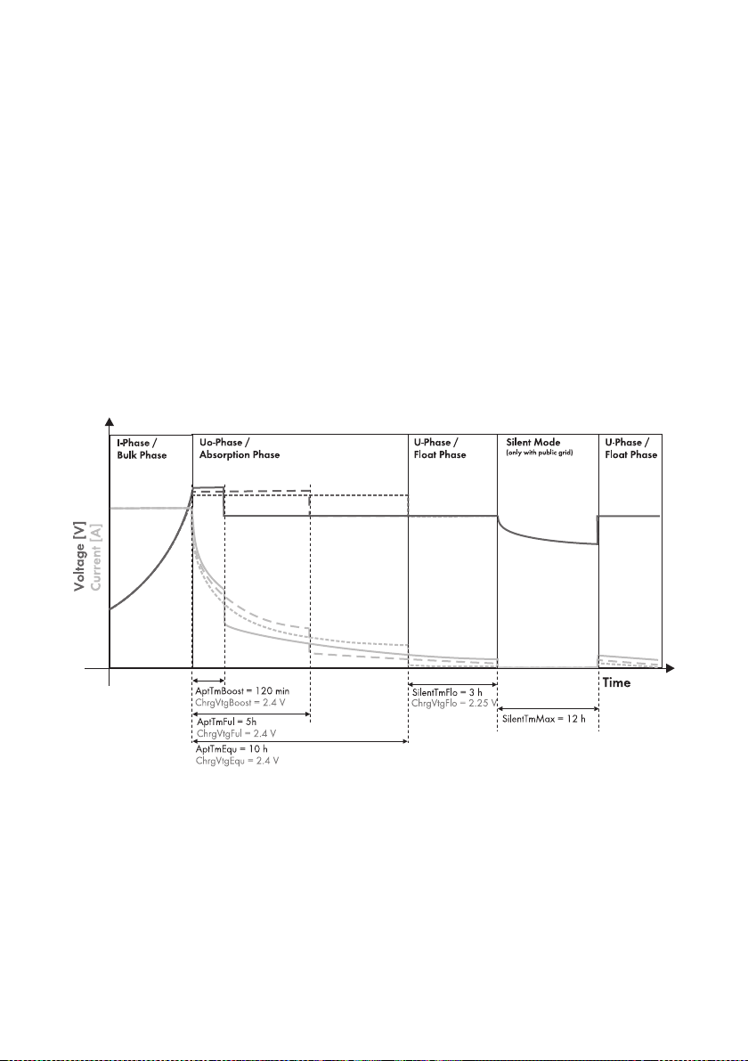
Battery management SMA Solar Technology AG
The battery's state of health (display value "320.01 Soh") is a measurement of the present useable
capacity expressed as a percentage relative to the nominal capacity. 100 % means that the entire
nominal capacity can be used. 50 % means that only half of the original nominal battery capacity
ca n be used. T he b att ery 's stat e of hea lth is also cal cul ated by means of a self-adapting method which,
however, can only produce good and exact values after a number of charging cycles.
The present capacity for the Sunny Island is automatically adjusted downwards for temperatures
< 20 °C, since the usable capacity of batteries is significantly reduced at temperatures below the
nominal temperature.
In case of lead acid batteries, the nominal capacity is adjusted by a fixed factor of − 1 %/°C.
For NiCd batteries a factor of − 0.75%/°C is used.
13.4 Charge control
The Sunny Island uses a three-phase charge control, using the IUoU procedure. When the device
operates with the public grid, there is also an optional fourth phase called silent mode.
The I stands for the constant current phase (I phase). In this phase, the charging is limited by the
maximum defined battery current (parameter "222.01 BatChrgCurMax"), the nominal grid current
(parameter "232.03 GdCurNom") or the maximum AC charging current of the Sunny Island
(parameter "210.02 InvChrgCurMax"). The respective value reached first is the limiting value.
During this phase the battery voltage increases as the battery is charged.
Once the battery voltage reaches the predefined value for the second phase Uo
("222.07 — 222.09", ChrgVtgBoost or ChrgVtgFul or ChrgVtgEqu parameters), the constant voltage
charging (absorption phase) begins.
94 SI5048-TEN093630 Technical Description
Page 95
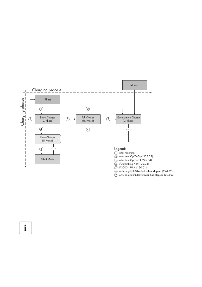
SMA Solar Technology AG Battery management
In thi s ph ase, th e ba tte ry volt age is m ain tained at a consta nt l eve l, r esu lti ng i n a cont inu all y decre asi ng
battery current. The Sunny Island remains in this phase for a defined period of time
("222.02 — 222.03", AptTmBoost or AptTmFul or AptTmEqu" parameters). For this charging phase,
th e Su nny Isl and aut oma tic all y se lec ts o ne o f th ree pos sib le c harging methods (boost, full, equalizing)
which are described in detail in sections 13.4.1”Boost Charge” (page96) to 13.4.3”Equalization
Charge” (page97). The remaining charging time (display value "120.04 AptTmRmg") of this phase
and the current process (display value "120.05 BatChrgOp") can be read on the display.
The following figure shows the relationship and the process diagram of the charging phases and
charging processes.
Once this constant voltage phase is finished, the Sunny Island switches to float charge which again
carries out constant voltage charging but at a greatly reduced charging voltage
("222.10 ChrgVtgFlo" parameter). The purpose of the float charge is to keep the battery in a fully
charged state without causing premature aging through overcharging. The Sunny Island remains in
this phase until either more than 30 % of the nominal capacity has been used (all discharges are
added up) or the state of charge is below 70 %. When the Sunny Island is operating on the
public grid, it can also switch from the float charge into silent mode.
Changing the charging voltage
The charging voltage does not rapidly change, but is slowly adjusted to the new nominal
va lue by a ppr ox. 0.5 mV/ cel l*s as t he c ons tan t volta ge p has e ch ang es t o th e float cha rge .
This also takes place if the nominal value is changed manually.
Technical Description SI5048-TEN093630 95
Page 96
Battery management SMA Solar Technology AG
The charging capability of batteries is highly dependent on the battery temperature. For temperatures
< 20 °C, the charging voltage must be slightly increased, and for temperatures > 20 °C it must be
slightly decreased. This is necessary to prevent overcharging and insufficient charging reliably at any
battery temperature. For this reason, the Sunny Island is equipped with automatic temperature
compensation of the charging voltage. The battery charging voltage is adjusted by:
• 4 mV/°C and cell, in the case of VLA and FRLA battery types
• 0 mV/°C and cell, in the case of NiCd batteries
The temperature compensation value can be set using the "222.11 BatTmpCps" parameter.
13.4.1 Boost Charge
Th e bo ost cha rge is t he m ost com mon cha rgi ng p roc ess of the S unn y Is lan d. T he b oos t ch arg e en sur es
a high generator workload through a high charging voltage over a short period of time. With liquid
FLA lead acid batteries, this charge process should be used for gassing and thus compensating the
electrolytes. The boost charge process can charge the battery up to approx. 85 % to 90 %.
13.4.2 Full Charge
Every 14 days or 8 nominal charge throughputs, the Sunny Island initiates a full charge automatically
(parameter "222.05 CycTmFul").
Nominal charge throughput
A nominal charge throughput is reached when the sum of the discharge currents
corresponds to the nominal capacity of the battery.
Example: The battery has a nominal capacity of 100 Ah. A nominal charge throughput is
reached when the battery has been discharged 10 times for 1 hour by 10 A.
The objective is to recharge the battery to a charge level of at least 95 % and to compensate the
possible effects of an insufficient charge. Regular full charging approximately every 2 to 4 weeks can
double the service life of the battery.
Change to a Full Charge
If the Sunny Island changes to full charge after a specific time of boost charging has
elapsed, the entire time of boost charge elapsed is considered for the full charge.
More than 1 % of the nominal capacity of the battery will be discharged
If more than 1 % of the battery's nominal capacity is discharged during a full charge,
50 % of the time elapsed is considered for the next constant voltage phase.
96 SI5048-TEN093630 Technical Description
Page 97
SMA Solar Technology AG Battery management
External charging device
If an external charger or charge controller is connected to the battery and the criteria for
a full charge are fulfilled due to external charging, the Sunny Island treats this as if it had
performed the full charge itself.
Procedures Parallel to the Full Charge
Any parallel procedures causing the generator to stop during the full charging process are
not taken into account until the charging process is completed.
13.4.3 Equalization Charge
A battery bank consists of many individual battery cells connected in series which all behave slightly
differently. Over time, this results in different charge levels in the individual cells. This can lead to
premature failure, initially of individual cells, and finally to failure of the entire bank.
The Sunny Island can perform an equalization charge automatically every 180 days
("222.06 CycTmEqu" parameter) or every 30 nominal charge throughputs. During this process, it
performs controlled overcharging of the battery bank to ensure that even the weaker cells are fully
recharged. Equalization charging extends the battery service life by up to 50 %. The automatic
equalization charging function can also be deactivated ("222.12 AutoEquChrgEna" parameter,
activated by default) or manually started ("520.01 ChrgSelMan" parameter).
Change to an Equalization Charge
If the Sunny Island changes to equalization charge after a specific time of boost charging
or full charging has elapsed, these times are completely considered for the equalization
charge.
More than 1 % of the nominal capacity of the battery will be discharged
If more than 1 % of the battery's nominal capacity is discharged during an equalization
charge, 50 % of the time elapsed is considered for the next constant voltage phase.
External charging device
If an external charger or charge controller is connected to the battery and the criteria for
a full charge are fulfilled due to external charging, the Sunny Island treats this as if it had
performed the full charge itself.
Technical Description SI5048-TEN093630 97
Page 98

Battery management SMA Solar Technology AG
13.4.4 Manual Equalization Charge
The parameter "520.01 ChrgSelMan" activates the manual equalization charg e on th e Sunn y Isla nd.
If a ge ner ato r is con nec ted to t he system, it is automatically started and stopped once the equalization
charge is completed.
Carrying out the Equalization Charge
An equalization charge should be performed at least once a year. After a long period of
time without charging, e. g., in the case of systems which are only operated seasonally,
manual equalization charges are required at the end or at the beginning of the season.
13.4.5 Silent Mode
In addition to the float charge, the silent mode can be used ("224.01 SilentEna" parameter), only
when operating on the public grid in the operation type "GridCharge".
The main purpose of the silent mode is to save energy by switching from charge mode to standby
mode in utility backup systems where the Sunny Island is predominantly in float charge.
The silent mode is activated after the time set for float charge ("224.02 SilentTmFlo" parameter)
has expired. The Sunny Backup system remains in silent mode for a fixed time ("224.03 SilentTmMax"
parameter) or until the battery voltage per cell is 0.14 V lower than the set voltage ("222.10 ChrgVtgFlo"
parameter). This ensures that the battery is always fully charged, even in silent mode.
If a gr id f ailu re i s de tec ted dur ing sile nt m ode , th e Su nny Isl and makes a stand-alone grid available within
10 sec.
98 SI5048-TEN093630 Technical Description
Page 99
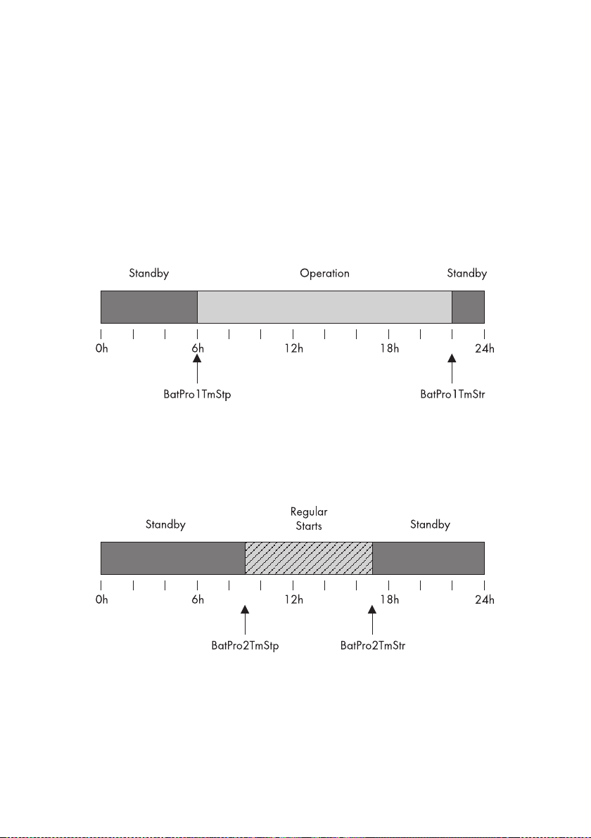
SMA Solar Technology AG Battery management
13.5 Battery Preservation Mode
The Sunny Island has a sophisticated battery preservation mode. The battery preservation mode
prevents deep discharge from the battery as far as possible when the energy supply is low, thus
preventing a total system failure as well as damage to the battery.
The battery preservation mode has three levels that are activated as a result of the state of charge
(when the charge drops below the respective limit, parameters "223.05 BatPro1Soc", "223.06
BatPro2Soc" and "223.07 BatPro3Soc"):
Level 1: The first level is used to switch the Sunny Island into standby mode at times when the energy
is not necessarily required (e.g., at night). You define the start time using the "223.01 BatPro1TmStr"
parameter and define the stop time using the "223.02 BatPro1TmStp" parameter.
Level 2: The second level of the battery preservation mode ensures that the Sunny Island is started
regularly every two hours only in the time period during which energy supply is expected, and that it
attempts to charge the battery from the AC side. In case of PV systems this time is during the day.
In this case, you define the start time using the "223.03 BatPro2TmStr" parameter and the stop time
using the "223.04 BatPro2TmStp" parameter.
Level 3: The third level ensures that the battery is protected from deep discharge and thus against
damage. In this case, the Sunny Island is switched off completely. To start it, see section
9.5”Reactivating the Device Following Automatic Shutdown” (page63).
At all three levels, the Sunny Island is stopped only if no battery current flows within 6 minutes
(limit 3 A charging current).
Technical Description SI5048-TEN093630 99
Page 100

Battery management SMA Solar Technology AG
The limits for all three levels can be set independently of each other. This allows individual levels to
be skipped.
Parameter BatPro1Soc < BatPro2Soc
If the BatPro1Soc parameter < BatPro2Soc, level 1 is skipped and only leve l 2 is car ried out .
For level 1 and 2, a hysteresis of 5 % of the SOC charge level is designated for exiting this state.
Battery preservation mode is not automatically exited if an external voltage source
(grid reconnection/generator start) is present.
The battery preservation mode can be exited by manually starting the Sunny Island. If, within
5 minutes (see above), charging current is detected, the Sunny Island continues to operate; otherwise,
it switches off again.
13.6 Battery Diagnostics
The "320# Battery Diagnosis" menu displays several values that provide information on the past
operational behavior of the battery. These values are helpful in checking the efficiency of the set
parameters and in viewing the typical operating conditions of the battery (see section
19.3”Diagnosis (300#)” (page172)).
100 SI5048-TEN093630 Technical Description
 Loading...