

SMA SUNNY TRIPOWER 60, SUNNY HIGHPOWER PEAK1, STP 60-10, STP 60-JP-10, SHP 75-10 Technical Information
...Page 1
F1
F2
F3
F4
Home
Back
OK
F1
F2
F3
F4
Home
Back
OK
Technical Information
SUNNY TRIPOWER 60 /
SUNNY HIGHPOWER PEAK1
Description of the Operating Parameters
STP60-SHP75-10-Parameter-TI-en-12 | Version 1.2ENGLISH
Page 2

Table of Contents
SMA Solar Technology AG
Table of Contents
1 Information on this Document..................................................................................................... 4
2 Grid Protection Settings ............................................................................................................... 4
2.1 Nominal Voltage ............................................................................................................................................. 4
2.2 Nominal Frequency......................................................................................................................................... 4
2.3 Voltage-Dependant Disconnection................................................................................................................. 4
2.3.1 Disconnection due to Undervoltage ............................................................................................................... 4
2.3.2 10-Minute Average Value............................................................................................................................... 5
2.3.3 Disconnection due to Overvoltage ................................................................................................................. 5
2.4 Manual Restart ................................................................................................................................................ 5
2.4.1 Activating Manual Restart ............................................................................................................................... 5
2.4.2 Events Causing Grid Faults.............................................................................................................................. 5
2.5 Frequency-Dependent Disconnection............................................................................................................. 6
2.5.1 Disconnection due to Underfrequency ........................................................................................................... 6
2.5.2 Disconnection due to Overfrequency ............................................................................................................. 6
2.6 Connection, Reconnection and Disconnection .............................................................................................. 6
2.6.1 Connection Time............................................................................................................................................... 6
2.6.2 Reconnection Time ........................................................................................................................................... 7
2.6.3 Short Interruption Time..................................................................................................................................... 7
2.6.4 Time to Alarm ................................................................................................................................................... 7
2.6.5 Voltage and Frequency Connection Limits ..................................................................................................... 7
2.6.6 Ramp-In............................................................................................................................................................. 7
3 Grid Failure................................................................................................................................... 7
3.1 Active Frequency Shift..................................................................................................................................... 7
3.2 Phase Failure Detection................................................................................................................................... 8
3.3 Rate of Change of Frequency......................................................................................................................... 8
4 Settings of Grid Management Services: Fault Ride-Through (FRT) .......................................... 9
5 Settings of Grid Management Services...................................................................................... 12
5.1 Default Settings................................................................................................................................................ 13
5.1.1 Selecting the Control Modes for Reactive Power Provision .......................................................................... 13
5.1.2 Night Mode...................................................................................................................................................... 14
5.1.3 Active Power Limitation for Reactive Power Feed-In ...................................................................................... 14
5.1.4 Nominal Apparent Power at Point of Common Coupling (PCC).................................................................. 14
5.1.5 Voltage Differences Between the Point of Common Coupling (PCC) and the PV System .......................... 14
5.1.6 Nominal Voltage.............................................................................................................................................. 15
5.2 Direct Control................................................................................................................................................... 15
5.2.1 Start Signal ....................................................................................................................................................... 15
5.2.2 Connection/Reconnection Ramp Rate............................................................................................................ 15
5.2.3 Time Delay Until Disconnection....................................................................................................................... 15
5.2.4 Reactive Power Ramp Rates ............................................................................................................................ 15
5.2.5 Active Power Ramp Rates................................................................................................................................ 16
5.2.6 Setting the Maximum Active Power ................................................................................................................ 16
5.2.7 Setting the Reactive Power .............................................................................................................................. 16
5.2.8 Setting the Power Factor (PF) .......................................................................................................................... 16
5.2.9 Setting the Apparent Power............................................................................................................................. 16
5.3 Control Modes................................................................................................................................................. 17
5.3.1 Q(U) - Reactive Power as a Function of Grid Voltage................................................................................... 17
5.3.2 Q(P) - Reactive Power as a Function of Active Power ................................................................................... 17
5.3.3 Q(S) - Reactive Power as a Function of Apparent Power.............................................................................. 18
5.3.4 Q(ext) - Reactive Power as a Function of an External Setpoint..................................................................... 18
5.3.5 PF(P) - Power Factor as a Function of Active Power....................................................................................... 18
Technical InformationSTP60-SHP75-10-Parameter-TI-en-122
Page 3

SMA Solar Technology AG
5.3.6 PF(U) - Power Factor as a Function of Grid Voltage...................................................................................... 18
5.3.7 PF(ext) - Power Factor as a Function of an External Setpoint........................................................................ 18
5.3.8 P(V) – Active Power as a Function of Grid Voltage....................................................................................... 19
5.3.9 P(f) - Active Power as a Function of Frequency.............................................................................................. 19
Table of Contents
Technical Information 3STP60-SHP75-10-Parameter-TI-en-12
Page 4

1 Information on this Document
SMA Solar Technology AG
1 Information on this Document
This document is valid for:
• STP60-10 (SunnyTripower60) from software version 1.80
• STP 60-JP-10 (SunnyTripower 60) from software version 1.80
• SHP 75-10 (SunnyHighpowerPeak1) from software version 1.90
• SHP 75-JP-10 (SunnyHighpowerPEAK1) from software version 2.0
This document is intended to help the user get a better understanding of the functionality of the inverter. The
descriptions refer to the parameter IDs which can also be found in the "Settings report".
The value ranges indicated in the following sections do not necessarily refer to the permissible ranges in accordance
with the applied standards, but are to reflect the performance of the inverter. All adjustable parameters have the same
indicated ranges and increments. Since not all parameters are used by all standards, the parameters that are not used
will be deactivated in the file "Inverter settings".
2 Grid Protection Settings
The following parameters for grid connection settings are saved in the inverter and only used here. The settings are
divided into groups. The groups reflect the various grid management services.
All requirements for grid protection settings are set at the inverter connection point.
2.1 Nominal Voltage
This parameter refers to the nominal grid voltage of a country. In most countries, only one official grid voltage is valid.
For countries with several official grid voltages, additional grid codes are provided so that the user is able to set the
grid voltage requested by the grid operator.
Parameter name Setting range
UNOM 220Vac to 277Vac (L-N)
2.2 Nominal Frequency
The nominal frequency can either be 50Hz or 60Hz, and for the most part only one of the two is used. For countries
where both frequency values are used, additional grid codes are provided so that the user is able to set the nominal
frequency requested by the grid operator.
Parameter name Setting range
FNOM 50Hz or 60Hz
2.3 Voltage-Dependant Disconnection
2.3.1 Disconnection due to Undervoltage
The undervoltage disconnection capability has two parameters in a set, the first parameter is the magnitude, which is
given in voltage, the second is the trip time, which is given in seconds. Undervoltage disconnection works in the way
that in case of grid failure below the value stated in UMIN, the inverter stays connected to the grid for the time period
stated in T_UMIN. After this time has elapsed, the inverter must disconnect from the utility grid. Depending on the
applied standard, these two values can either be a maximum, minimum or mean value. Refer to the relevant standard
to see which of the three key values is used in your file.
Parameter name Setting range Step size
UMIN 23Vac (L-N) to UNOM 0.1 Vac (L-N)
T_UMIN 0.05s to 90.0s 0.01s
Technical InformationSTP60-SHP75-10-Parameter-TI-en-124
Page 5

SMA Solar Technology AG
2 Grid Protection Settings
2.3.2 10-Minute Average Value
The ten-minute average value is defined in the standard EN50160 as maximum threshold for a continuous high
voltage in the grid. If this value is exceeded, the inverter is disconnected from the utility grid.
Parameter name Setting range Step size
U10M_AVG UNOM to 350Vac (L-N) 0.1 Vac (L-N)
T_U10M_AVG 0.05s to 90.0s 0.01s
2.3.3 Disconnection due to Overvoltage
The overvoltage disconnection function has two related values: the first value indicates the voltage level in volt, the
second value indicates the tripping time in seconds. Overvoltage disconnection works in the way that if the grid
voltage exceeds the value stated in UMAX, the inverter stays connected to the grid for the time period stated in
T_UMAX. After this time has elapsed, the inverter must disconnect from the utility grid. Depending on the applied
standard, these two values can either be a maximum, minimum or mean value. Refer to the relevant standard to see
which of the three key values is used in your file.
Parameter name Setting range Step size
UMAX UNOM to 350Vac (L-N) 0.1 Vac (L-N)
T_UMAX 0.05s to 90.0s 0.01s
2.4 Manual Restart
With the function Manual Restart, you can configure whether the inverter is to revert to feed-in operation automatically
after the fault has occurred, or whether feed-in operation should remain interrupted until it is manually reactivated.
2.4.1 Activating Manual Restart
The parameter RST_MOD activates the manual restart. A value of 1 causes that the user must start the inverter after a
grid fault. A value of 0 causes that the inverter reverts to feed-in operation automatically after the grid fault has been
rectified.
Parameter name Setting option
RST_MOD on (1), off (0)
2.4.2 Events Causing Grid Faults
The following events cause the inverter to interrupt feed-in operation and that the feed-in operation must be activated
through manual restart.
• Overvoltage
• Undervoltage
• Active islanding detection
• Passive islanding detection
• Overfrequency
• Underfrequency
If one of the parameters is set to value 1 and a corresponding grid fault occurs, a specific event is generated and the
inverter interrupts the feed-in operation until it is restarted manually.
Parameter name Setting option
MAN_RST_OV_VTG on (1), off (0)
Technical Information 5STP60-SHP75-10-Parameter-TI-en-12
Page 6

2 Grid Protection Settings
Parameter name Setting option
MAN_RST_UN_VTG on (1), off (0)
MAN_RST_OV_FREQ on (1), off (0)
MAN_RST_UN_FREQ on (1), off (0)
MAN_RST_PID on (1), off (0)
MAN_RST_AID on (1), off (0)
SMA Solar Technology AG
2.5 Frequency-Dependent Disconnection
2.5.1 Disconnection due to Underfrequency
The underfrequency disconnection function has two related values: the first value indicates the frequency level in Hertz,
the second value indicates the tripping time in seconds. Underfrequency disconnection works in the way that if the grid
frequency drops below the value stated in FMIN, the inverter stays connected to the grid for the time period stated in
T_FMIN. After this time has elapsed, the inverter must disconnect from the utility grid. Depending on the applied
standard, these two values can either be a maximum, minimum or mean value. Refer to the relevant standard to see
which of the three key values is used in your file.
Parameter name Setting range Step size
FMIN 45Hz to FNOM 0.01 Hz
T_FMIN 0.05s to 90.0s 0.01s
2.5.2 Disconnection due to Overfrequency
The overfrequency disconnection function has two related values: the first value indicates the frequency level in Hertz,
the second value indicates the tripping time in seconds. Overfrequency disconnection works in the way that if the
power frequency exceeds the value stated in FMAX, the inverter stays connected to the grid for the time period stated
in T_FMAX. After this time has elapsed, the inverter must disconnect from the utility grid. Depending on the applied
standard, these two values can either be a maximum, minimum or mean value. Refer to the relevant standard to see
which of the three key values is used in your file.
Parameter name Setting range Step size
FMAX FNOM to 66Hz 0.01 Hz
T_FMIN 0.05s to 90.0s 0.01s
2.6 Connection, Reconnection and Disconnection
2.6.1 Connection Time
The connection time is the time period of grid monitoring between start of the inverter and start of grid feed-in.
Parameter name Setting range Step size
T_CON 0s to 1800s 0.01s
Technical InformationSTP60-SHP75-10-Parameter-TI-en-126
Page 7

SMA Solar Technology AG
3 Grid Failure
2.6.2 Reconnection Time
If a fault on the grid makes the inverter disconnect and the grid then afterwards stabilizes within the allowed voltage
and frequency ranges, then the inverter is allowed to reconnect to the grid with this time delay. The reconnection time
is usually shorter than the connection time, but it can also be the same time or longer than the connection time.
Parameter name Setting range Step size
T_RECON 0s to 1800s 0.01s
2.6.3 Short Interruption Time
The short interruption time is the permissible time period after which the inverter must start the complete reconnection
procedure. If the grid fault is remedied in a shorter time period, the inverter can reconnect to the utility grid after the
reconnection time T_RECON.
Parameter name Setting range Step size
T_SHT_INT 0s to 1800s 0.01s
2.6.4 Time to Alarm
Time to alarm is the period which the inverter must wait before generating an alarm event. This is to prevent the inverter
from generating alarm events all the time.
Parameter name Setting range Step size
T_ALARM 0s to 1800s 0.01s
2.6.5 Voltage and Frequency Connection Limits
The minimum and maximum connection limits for voltage and frequency define the value range in which the inverter
can connect to the utility grid.
Parameter name Setting range Step size
UMIN_CON UMIN1 to UNOM 0.1V
UMAX_CON UNOM to UMAX1 0.1V
FMIN_CON FMIN1 to FNOM 0.01 Hz
FMAX_CON FNOM to FMAX1 0.01 Hz
2.6.6 Ramp-In
The ramp-in factor describes the ramp for the power up of the inverter. More details can be found in the settings for
grid management services under parameter Connection/reconnection ramp rate.
3 Grid Failure
3.1 Active Frequency Shift
The active frequency shift works in the way that if the grid becomes unstable for any reason, this function then helps to
push the grid even more of balance so that the inverter disconnects due to RoCoF or one of the regular disconnection
parameters.
Parameter name Setting options
LOM_F_SHF_K0/_K1 on (1)
off (0)
Technical Information 7STP60-SHP75-10-Parameter-TI-en-12
Page 8

3 Grid Failure
SMA Solar Technology AG
3.2 Phase Failure Detection
The phase failure detection is used to determine the failure of one or more line conductors of the utility grid. In case of
a grid failure, the grid relays open.
Parameter name Setting options
OPEN_PH_DETECT on (1)
off (0)
The ramp-in factor describes the ramp for the power up of the inverter. More details can be found in the settings for
grid management services under parameter Connection/reconnection ramp rate.
3.3 Rate of Change of Frequency
The parameter RoCoF or Rate of Change of Frequency measures the change in frequency. If the change in
frequency exceeds the stated maximum limit for a longer period of time, the inverter disconnects from the utility grid.
The frequency can change very rapidly if one or several line conductors fail.
Parameter name Setting range Step size
LOM_ROC 0Hz/s to 10Hz/s 0.01 Hz/s
LOM_ROC 0Hz/s to 10Hz/s 0.01 Hz/s
T_LOM_ROC 0s to 1800s 0.01s
LOM_ROC_THR 0Hz to 5.0Hz 0.01 Hz
Technical InformationSTP60-SHP75-10-Parameter-TI-en-128
Page 9
SMA Solar Technology AG
4 Settings of Grid Management Services: Fault Ride-Through (FRT)
4 Settings of Grid Management Services: Fault Ride-Through (FRT)
The inverter is equipped with the Fault Ride-Through function for both undervoltage (LVRT) and overvoltage (HVRT/
OVRT) situations. Although the FRT function belongs to grid management services, it is stored in the inverter. The FRT
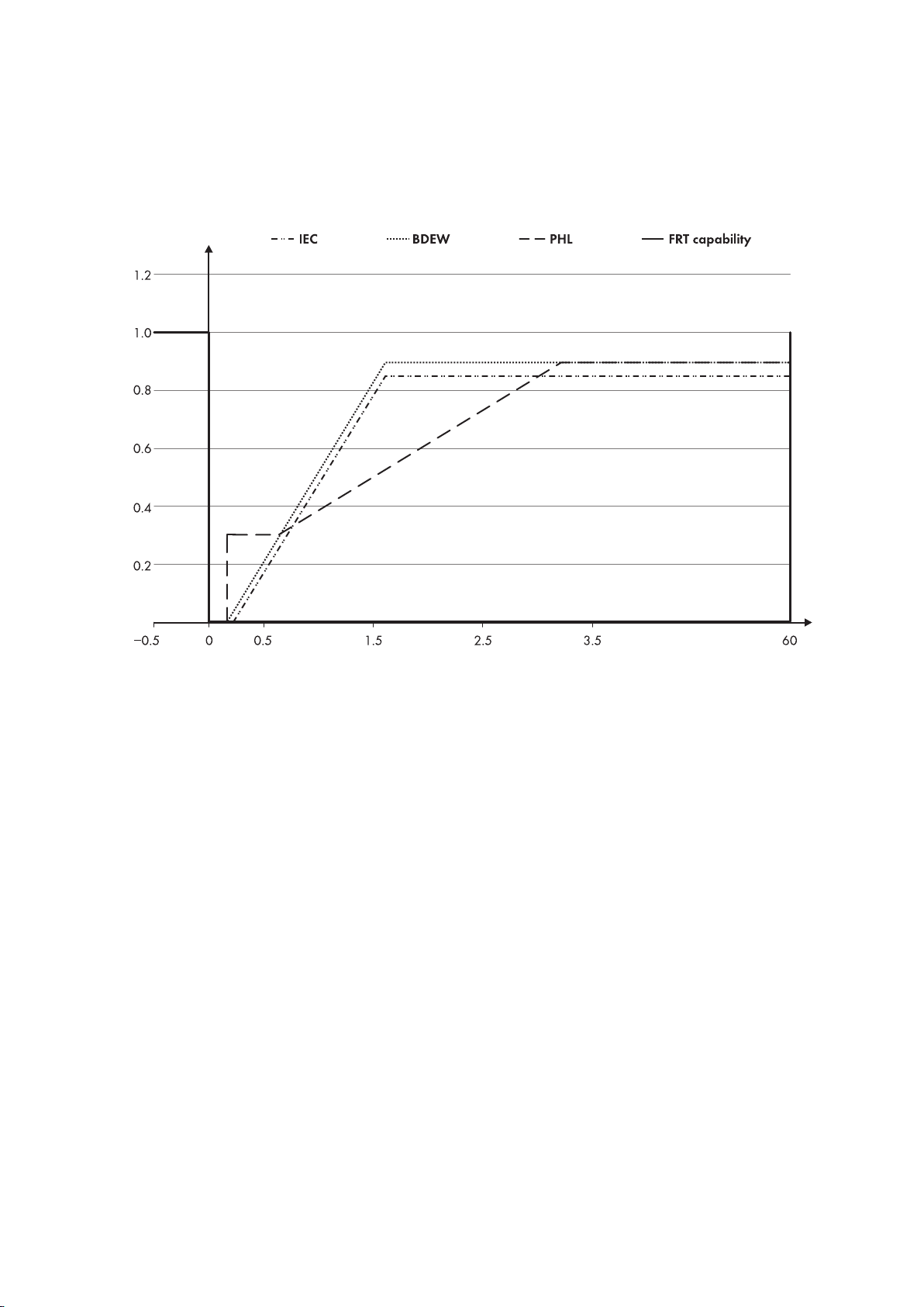
function is set to cope with voltage dips down to 0% UNOM without time limit. This is confirmed in the FRT
performance test which was manually stopped after 60 seconds (see figure 1).
Figure 1: The FRT function of the inverter has been tested at 60 kW and three-phase voltage dips down to 80% UNOM, 50% UNOM, 20%
UNOM, 5% UNOM. The performance test was manually stopped after 60 seconds.
The parameter FRT_MODE is used to set the FRT operating mode for current feed-in. There are six selectable
operating modes.
Technical Information 9STP60-SHP75-10-Parameter-TI-en-12
Page 10
4 Settings of Grid Management Services: Fault Ride-Through (FRT)
SMA Solar Technology AG
For reactive power feed-in, the positive and negative sequence components are considered separately. The half-cycle
root-mean-square values of the positive and negative sequence components of the grid voltage during the grid fault
are compared with the average root-mean-square values before the fault. The relevant time frame for the average
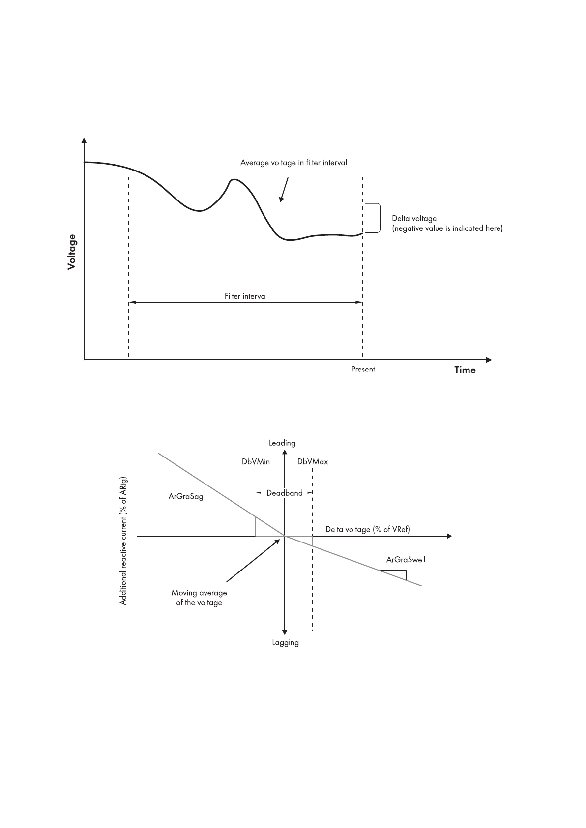
voltage before the grid fault can be set via the parameter FRT_T_U_AVG (default 10 minutes). Figure 2 shows the
functionality of the parameter FRT_T_U_AVG.
Figure 2: FRT voltage average as a function of time (IEC61850-90-7)
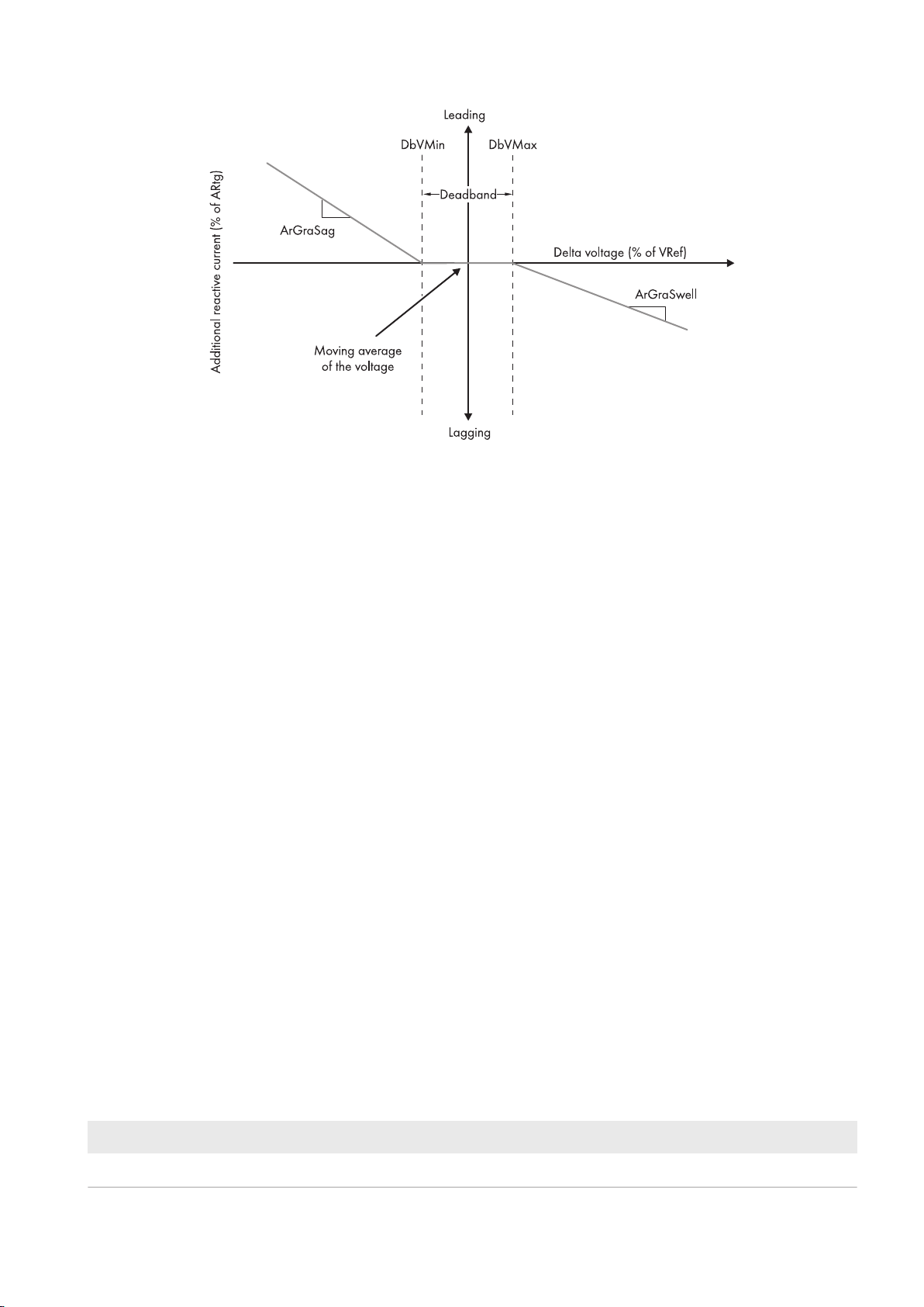
The voltage differences (DeltaU_pos and DeltaU_neg) are passed through one of the following Iq(V) characteristic
curves. The choice of the characteristic curve depends on parameter FRT_IQ_MODE (default: 0).
Figure 3: FRT_IQ_MODE = 0: as per BDEW (IEC 62850-90-7)
Technical InformationSTP60-SHP75-10-Parameter-TI-en-1210
Page 11
SMA Solar Technology AG
Figure 4: FRT_IQ_MODE = 1: as per SDLWind (IEC 62850-90-7)
4 Settings of Grid Management Services: Fault Ride-Through (FRT)
In both operating modes, there is a common set of parameters which have to be set for the FRT functionality to work
properly:
1. The deadband is defined by two thresholds: the lower threshold FRT_ULOW and the upper threshold FRT_UUP.
2. For the positive sequence component, the gradient K for the slope of voltage dips is defined by
FRT_DIDU_POS_LVRT and for the slope of voltage increase by FRT_DIDU_POS_HVRT.
3. For the negative sequence component, the gradient K for the slope of voltage dips is defined by
FRT_DIDU_NEG_HVRT and for the slope of voltage increase by FRT_DIDU_NEG_HVRT.
The additional reactive current is added to the pre-fault reactive current value.
The positive sequence components have priority over the negative sequence components. Thus, first the negative
sequence component is limited if the current limitation is reached. In case that Id has higher priority than Iq, the reactive
currents will be limited in such way as the total current does not exceed the limit.
After fault clearance, reactive current feed-in stays active for a certain transition period. This period can be set with the
grid code parameter FRT_T_TRANS.
Active current is fed in under the following conditions:
1. Active current feed-in is activated in accordance with the selection made in FRT_MODE (operating modes 3, 4,
and 5).
2. The current reactive power value allows additional active current without the total current being greater than the
nominal current.
3. There is enough primary input power.
Restriction: active power feed-in during fault is upwards limited to the pre-fault active power, even if higher primary
input power is (or becomes) available during the fault.
After the fault, the active power returns to its initial level with first order dynamic. The recovery time can be set via the
parameter FRT_T_P_RECOV.
If required, it is possible to set up a so-called blocking zone during the grid fault: if the voltage falls below a
configurable limit FRT_U_BLK, power generation is ceased after a configurable time FRT_T_BLK. Over the blocking
zone FRT_U_BLK there is the hysteresis band determined by FRT_U_BLK_HYS. Once voltage exceeds this hysteresis
band again, power generation is continued.
Parameter name Setting range/setting option Increment/explanation
FRT_ULOW 10% to 100% 1%
Technical Information 11STP60-SHP75-10-Parameter-TI-en-12
Page 12

5 Settings of Grid Management Services
Parameter name Setting range/setting option Increment/explanation
FRT_UUP 100% to 130% 1%
FRT_MODE 0: Frt_Off The FRT function is deactivated.
1: Frt_ZeroCurrent No current feed-in
2: Frt_ReactiveOnly Reactive current is fed in, but no ac-
tive current.
3: Frt_ActiveOnly Active current is fed in, but no reac-
tive current.
4: Frt_Full_IqPriority The reactive current is fed in. If PV
power is available, the total current is
supplied with active current until current limitation is reached.
5: Frt_Full_IdPriority The maximum possible active current
is fed in. Starting from the grid code
characteristic curve, the total current
is supplied with reactive current until
the current limitation is reached.
SMA Solar Technology AG
FRT_DIDU_POS_LVRT 1 to 10 0.1
FRT_DIDU_POS_HVRT 1 to 10 0.1
FRT_DIDU_NEG_LVRT 1 to 10 0.1
FRT_DIDU_NEG_HVRT 1 to 10 0.1
FRT_IQ_MODE 0 or 1 -
FRT_T_BLK 0s to 10s 0.01s
FRT_T_TRANS 0s to 10s 0.01s
FRT_T_U_AVG 0s to 1800s 1s
FRT_U_BLK 0% to 100% 1%
FRT_U_BLK_HYS 0% to 100% 1%
5 Settings of Grid Management Services
The following parameters for grid management services are loaded to the SMAInverterManager(IM) and only used
here. The settings are divided into groups. The groups reflect the various grid management services (control modes).
The value ranges indicated in the following sections do not necessarily describe the permissible ranges in accordance
with the grid code, but are to reflect the performance of the inverter. Since not all parameters are used by all
standards, the parameters that are not used will be deactivated in the file "Grid Code".
Regarding the signs for reactive power and power factor (PF), plus means overexcited reactive power (grid voltage is
increased) and minus means underexcited reactive power (grid voltage is reduced).
Technical InformationSTP60-SHP75-10-Parameter-TI-en-1212
Page 13
SMA Solar Technology AG
SMA INVERTER
MANAGER
Start/Stop control
Setpoint for P, Q, PF
Parameters for control modes
Point of
interconnection
P & Q
grid grid
U & f
grid grid
POWER METER
POWER METER
P & Q
grid grid
U & f
grid grid
INVERTER
LOCAL LOAD
(P Q)&
5 Settings of Grid Management Services
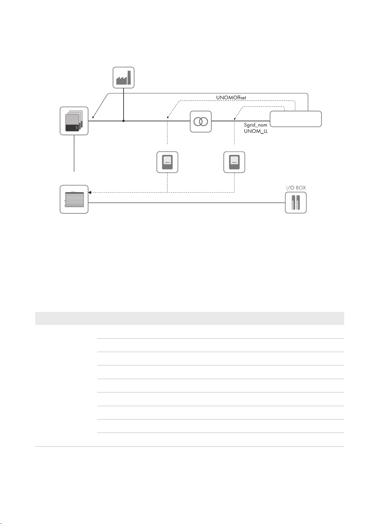
All requirements for grid management services are given for the point of common coupling (PCC).
Figure 5: Overview of a system with inverters, SMAInverterManager, local load, power meter and definition of Point of Common Coupling
(PCC).
5.1 Default Settings
5.1.1 Selecting the Control Modes for Reactive Power Provision
Reactive power references can either be given as a direct reference for reactive power (Q) or as an indirect reference
via the power factor (PF). The references are based on the following control modes (setting options), can be set with
the number 1 to 9 in the parameter ModeSelect.
Parameter name Setting option Explanation
ModeSelect 1 Q(U) - Reactive Power as a Function of Grid Voltage
2 Q(P) - Reactive Power as a Function of Active Power
3 Q(S) - Reactive power as a function of apparent power
4 Control mode is in implementation phase
5 Q(ext) - Reactive power as a function of an external setpoint (default)
6 PF(U) - Power Factor as a Function of Grid Voltage
7 PF(P) - Power Factor as a Function of Active Power
8 Control mode is in implementation phase
9 PF(ext) - Power factor as a function of an external setpoint
Technical Information 13STP60-SHP75-10-Parameter-TI-en-12
Page 14

5 Settings of Grid Management Services
SMA Solar Technology AG
5.1.2 Night Mode
The system with an inverter provides reactive power also in night mode. Therefore, the inverters are not switched off
after sunset. Information: If no primary energy source is available, only the control modes 1 to 5 can be used for
reactive power provision.
In the inverter, no switch-on circuit is installed. Thus, the inverter cannot start-up / reconnect to the grid after a voltage
dip when no DC-voltage is present. The voltage of the DC busbar is directly connected to the PV arrays at night. Thus,
current can flow in the arrays. This can only be prevented via one of the following measures: using string diodes in the
DC String-Combiner or using a controllable switch in the DC String-Combiner.
Parameter name Setting option Explanation
NightMode 0 Deactivated (Default)
1 Activated
5.1.3 Active Power Limitation for Reactive Power Feed-In
Some grid codes require that the PV system can also be operated during feed-in of nominal reactive power at nominal
active power. Example: A PV system is required to have a controllable power factor (PF) between ±0.9 and 1.0
without affecting the generation of active power. Thus, the nominal active power is no longer 100% but rather 90% so
that the parameter P_LIM_IF_Q should be set to 90%.
Parameter name Setting option
P_LIM_IF_Q 80% to 100% (default: 100%)
5.1.4 Nominal Apparent Power at Point of Common Coupling (PCC)
All grid management services in the inverter are based on the nominal apparent power at the point of common
coupling. Example: At an active power limitation to 50%, the active power at the point of common coupling is limited
to 50% by Sgrid_nom. The default value is "blank" meaning that the PV system uses the sum of apparent power from
the commissioned inverters. In some cases the installed power of the PV system is higher than agreed upon with the
distribution grid operator. Thus, the Sgrid_nom parameter should be set according to the contract clauses. In cases
where the PV system is installed to supply local loads (this requires an external power meter) and no active power is
allowed to be fed into the grid, the Sgrid_nom parameter should be left "blank" and the parameter P_ref should be
set to 0%.
Parameter name Setting option
Sgrid_nom blank, 0kVA to 4000kVA (default: blank)
5.1.5 Voltage Differences Between the Point of Common Coupling (PCC) and the PV System
This parameter serves to compensate for possible voltage differences on the cables between the inverters and the PCC
and is called up in the case where voltage-based control modes are used, i.e. Q(U), PF(U) and P(U). Thus, only a
single characteristic curve is required for different PV systems and only the parameter UNOMOffset (line to line
voltage) needs to be set for each PV system.
Parameter name Setting option
UNOMOffset 0, generally between ±10 V for low-voltage grids and
±1000 V for medium-voltage grids (default: 0)
Technical InformationSTP60-SHP75-10-Parameter-TI-en-1214
Page 15

SMA Solar Technology AG
5 Settings of Grid Management Services
5.1.6 Nominal Voltage
This parameter refers to the nominal grid voltage at the point of common coupling. The parameter is used to scale the
grid voltage for the control modes where the grid voltage is the independent variable, i.e. for Q(U), PF(U) and P(U). If
no external energy meter is used, this parameter should have the same value as UNOM in the protection part of the
grid code file. This also applies if an external energy meter is switched on the low-voltage (LV) side of the transformer.
If an external power meter is connected to the medium-voltage (MV) side of the transformer, the corresponding
nominal values for the grid voltage must be set, e.g. 33 kV.
Parameter name Setting option
UNOM_LL 200V to 480V (default: 398V) for low-voltage grids
and 3300V to 33000V for medium-voltage grids
5.2 Direct Control
5.2.1 Start Signal
The PV system can be disconnected immediately from the grid or it can be set that it connects to the grid once the grid
parameters (voltage level and frequency) are within the permissible range for connection (see Section2 "Grid
Protection Settings", page4).
Parameter name Setting option Explanation
ReleaseToStart 0 Immediate disconnection
1 Connection when grid parameter is in the permissible range (default)
5.2.2 Connection/Reconnection Ramp Rate
The active power is ramped according to this setting whenever the inverter is connected / reconnected to the grid, i.e.
when starting up in the morning, when starting up after the parameter ReleaseToStart is set to 1 and after
disconnection due to overvoltage or undervoltage, overfrequency or underfrequency etc.
Parameter name Setting range Step size
RmpIncTmm_ONLINE 0.6%/min to 1200%/min (default:
10%/min)
0.1%
5.2.3 Time Delay Until Disconnection
Controlled disconnection over the defined time period, this means the power will be ramped down in a controlled
manner over the delay period.
Parameter name Setting range Step size
T_DELAY_SHUTDOWN 0s to 600s (default: 2s) 0.2s
5.2.4 Reactive Power Ramp Rates
The reactive power is ramped according to this setting whenever the setpoint for reactive power is changed (both for
external setpoints and for other control modes, e.g. Q(U) or PF(P)). Note that two parameters are available: one for
decreasing and one for increasing setpoints.
Parameter name Setting range Step size
RmpDecTmm_Q -0.6%/min to -1200%/min (default) 0.1%
RmpIncTmm_Q 0.6%/min to 1200%/min (default) 0.1%
Technical Information 15STP60-SHP75-10-Parameter-TI-en-12
Page 16

5 Settings of Grid Management Services
SMA Solar Technology AG
5.2.5 Active Power Ramp Rates
The active power is ramped according to these setting whenever the external setpoint for active power is changed.
Note that two parameters are available: one for decreasing and one for increasing setpoints.
Parameter name Setting range Step size
RmpDecTmm_EXT -0.6%/min to -1200%/min (default) 0.1%
RmpIncTmm_EXT 0.6%/min to 1200%/min (default) 0.1%
5.2.6 Setting the Maximum Active Power
The active power is limited according to this parameter.
Parameter name Setting range Step size
P_ref 0% to 100% (default) 0.1%
5.2.7 Setting the Reactive Power
This parameter indicates the reactive power setpoint (only available if control mode 5 has been selected in the
parameter ModeSelect).
Parameter name Setting range Step size
Q_ref 0% to ±100% (default: 0%) 0.1%
5.2.8 Setting the Power Factor (PF)
This parameter indicates the setpoint for the power factor (PF) (only available if control mode 9 has been selected in
the parameter ModeSelect).
Parameter name Setting range Step size
PF_ref 0.8 to 1.0 for overexcitation
-0.8 to -1.0 for underexcitation (default)
0.01
5.2.9 Setting the Apparent Power
Some grid codes require that the PV system always generates a certain amount of apparent power, i.e. the system
operates within a unit circle in the PQ diagram. If the parameter S_ref is set to 60%, the PV system does not generate
reactive power until the active power is above 60%. However, if the active power is lower than 60%, the PV system
starts to generate reactive power to keep the apparent power at 60%. If the sign is positive, the PV system will
exchange overexcited reactive power. If the sign is negative, the system will exchange underexcited reactive power.
This type of control mode should not be used when a local load is connected, since it could cause the PV system to
lower the production of active power (only available if control mode 3 has been selected in the parameter
ModeSelect).
Parameter name Setting range Step size
S_ref 0% to ±100% (default: 0%) 0.1%
Technical InformationSTP60-SHP75-10-Parameter-TI-en-1216
Page 17
SMA Solar Technology AG
5 Settings of Grid Management Services
5.3 Control Modes
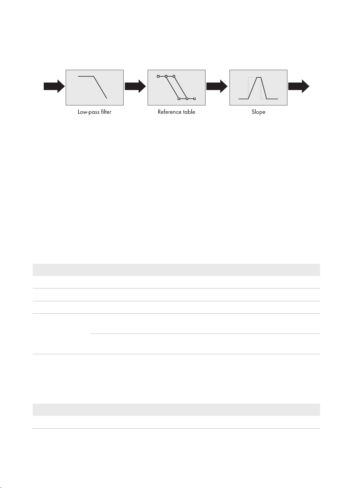
The general approach for the control modes is based on the structure in the technical report of the standard
IEC61850-90-7 (see the figure below).
Up to five parameters are used to program the local modes depicted above. The parameter RmpTmsPT1 is the rise
time from 0% to 95% (equal to 3τ) for the low-pass filter applied on the independent variable (e.g. grid voltage). The
reference table is made of two characteristic curves each containing up to ten break-points. One characteristic curve is
used when the independent variable is increasing and the other when decreasing. In this way, hysteresis can be
included in the reference table. Finally, the parameters RmpIncTmm and RmpDecTmm are the ramp rates for
increasing and decreasing output values (dependent variable) from the reference table.
Independent ramp rates are only available for control modes for active power, whereas for reactive power the ramp
rates are always given by the parameters RmpDecTmm_Q and RmpIncTmm_Q. If the input value (independent
variable) of the reference table exceeds the values defining the characteristic curves, the output value (dependent
variable) of the reference table is given as the first or last value in the characteristic curve respectively.
5.3.1 Q(U) - Reactive Power as a Function of Grid Voltage
This control mode uses the grid voltage to generate a reference value for the reactive power so that the grid voltage
can be controlled at the point of common coupling. The control mode contains two additional parameters for
activation. The mode is activated when the active power is above the set threshold and deactivated again when the
active power is below the set threshold. The threshold for activation must be larger than or equal to the threshold for
deactivation. If this control mode shall always be available, set lock_in_UQ = lock_out_UQ = 0% (only available if
control mode 1 has been selected in the parameter ModeSelect).
Parameter name Setting range Step size
RmpTmsPT1_UQ 0.6s to 3600s 0.01s
lock_in_UQ 0% to 100% of active power 0.1%
lock_out_UQ 0% to 100% of active power (must be smaller than lock_in_UQ) 0.1%
Q_of_U U: Grid voltage (independent values) from 80% to 120% of nominal
voltage
Q: Reactive power (dependent values) from -100% to 100% of nominal power
-
-
5.3.2 Q(P) - Reactive Power as a Function of Active Power
This control mode uses the active power to generate a reference value for the reactive power so that the grid voltage
can be controlled at the point of common coupling. The independent variable (grid power) can be negative if an
external energy meter is installed and the PV system must compensate for a local load (only available if control mode
2 has been selected in the parameter ModeSelect).
Parameter name Setting range Step size
RmpTmsPT1_PQ 0.6s to 3600s 0.01s
Technical Information 17STP60-SHP75-10-Parameter-TI-en-12
Page 18

5 Settings of Grid Management Services
Parameter name Setting range Step size
SMA Solar Technology AG
Q_of_P P: Active power (independent values) from -100% to 100% of nomi-
nal power
Q: Reactive power (dependent values) from -100% to 100% of nominal power
-
-
5.3.3 Q(S) - Reactive Power as a Function of Apparent Power
See above, Section "Maximum apparent power" (only available if control mode 3 has been selected in the parameter
ModeSelect).
5.3.4 Q(ext) - Reactive Power as a Function of an External Setpoint
See above, Section "Maximum reactive power" (only available if control mode 5 has been selected in the parameter
ModeSelect).
5.3.5 PF(P) - Power Factor as a Function of Active Power
This control mode uses the nominal active power to generate a reference value for the power factor (PF) so that the
grid voltage can be controlled at the point of common coupling. The control mode contains two additional parameters
for activation. The control mode is activated when the grid voltage is above the lock-in threshold and deactivated when
the grid voltage is below the lock-out threshold. The threshold for activation must be larger than or equal to the
threshold for deactivation. If this control mode shall always be available, set lock_in_PPF = lock_out_PPF = 90%
(only available if control mode 6 has been selected in the parameter ModeSelect).
Parameter name Setting range Step size
RmpTmsPT1_PPF 0.6s to 3600s 0.01s
lock_in_PPF 80% to 120% of grid voltage 0.1%
lock_out_PPF 80% to 120% of grid voltage (must be smaller than lock_in_PPF) 0.1%
PF_of_P P: Grid active power (independent values) from -100% to 100% of
nominal apparent power
PF: Power factor (dependent values) from ±0.8 to 1.0 -
-
5.3.6 PF(U) - Power Factor as a Function of Grid Voltage
This control mode uses the grid voltage to generate a reference value for the power factor (PF) so that the grid voltage
can be controlled at the point of common coupling (only available if control mode 7 has been selected in the
parameter ModeSelect).
Parameter name Setting range Step size
RmpTmsPT1_UPF 0.6s to 3600s 0.01s
PF_of_U U: Grid voltage (independent values) from 80% to 120% of nominal
voltage
-
PF: Power factor (dependent values) from ±0.8 to 1.0 -
5.3.7 PF(ext) - Power Factor as a Function of an External Setpoint
See above, Section "Maximum power factor" (only available if control mode 9 has been selected in the parameter
ModeSelect).
Technical InformationSTP60-SHP75-10-Parameter-TI-en-1218
Page 19
SMA Solar Technology AG
5 Settings of Grid Management Services
5.3.8 P(V) – Active Power as a Function of Grid Voltage
This control mode uses the grid voltage to generate a threshold for the active power so that the grid voltage can be
controlled at the point of common coupling. The P(V) characteristic curve must be coordinated with the Q(U) or PF(U)
control modes.
Parameter name Setting range Step size
RmpTmsPT1_UP 0.6s to 3600s 0.01s
RmpDecTmm_UP -0.6%/min to -1200%/min (default) 0.1%
RmpIncTmm_UP 0.6%/min to 1200%/min (default) 0.1%
P_of_U U: Grid voltage (independent values) from 80% to 120% of nominal
voltage
P: Active power (dependent values) from -100% to 100% of nominal
power
-
-
5.3.9 P(f) - Active Power as a Function of Frequency
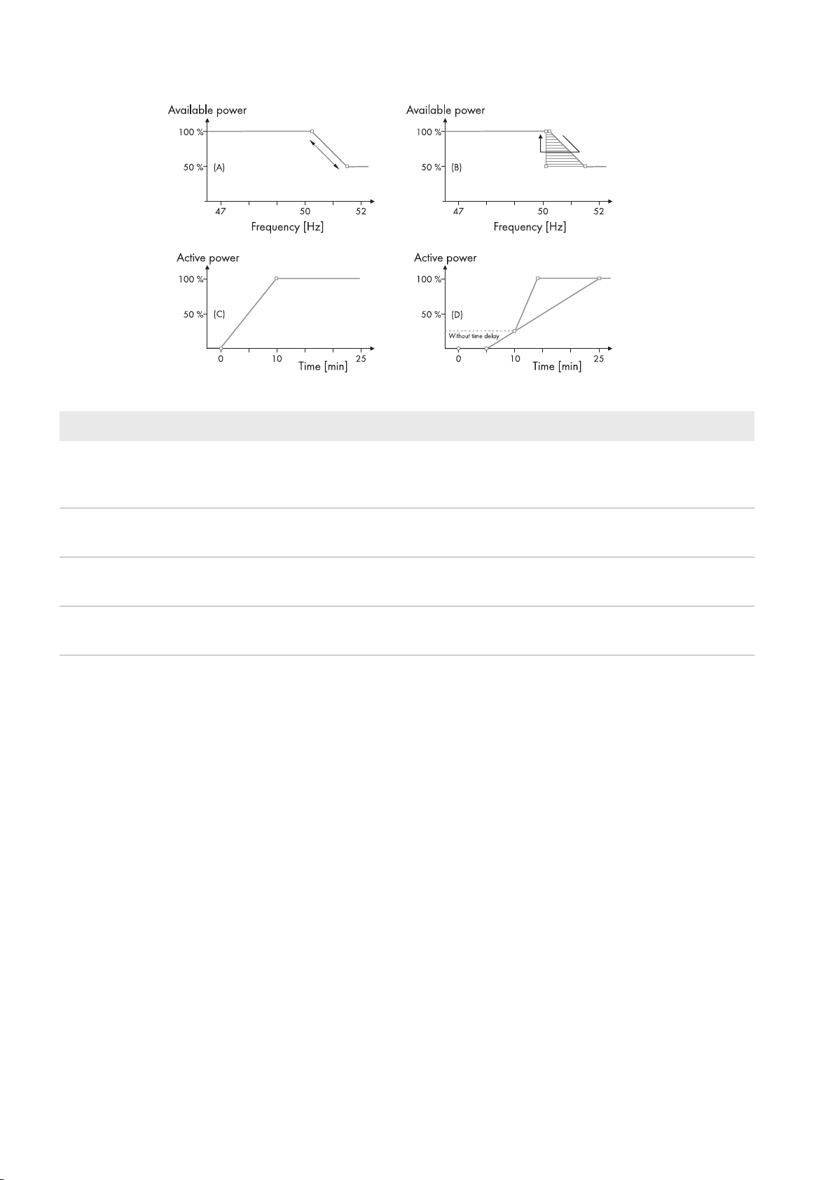
This is the common type of primary frequency control applied, e.g. as per the BDEW (German Association of Energy
and Water Industries) technical guidelines, with some extensions, see the figure below. By using the parameter
tdelay_on, it is possible to add a delay between the point in time where the frequency reaches its threshold (e.g.
50.2Hz) and the point in time where the active power starts to decrease. The purpose of this time delay is to reach a
lower sensitivity in terms of transient frequency changes and higher reliability when detecting grid failures. The amount
of generated active power is still sampled and hold at the instant where the frequency exceeds the threshold. Some
grid codes, e.g. CEI0-16, requires that the generation of active power is kept low in a certain duration after the
frequency has returned back to its normal range. This can be set via the parameter tdelay_off. Once the frequency is
back to its normal range, the active power is ramped up again with a certain ramp rate. This is done via the parameter
RmpIncTmm_FPReg. Some grid codes, e.g. CEI0-16, require that the ramp rate is variable. This can be
programmed with the parameter variable.
Hysteresis can be added in the P(f) curve, e.g. as per BDEW, by programming two P(f) characteristic curves with the
same values. Information: Active power will not start to increase again before the output value from the reference table
is equal to 100%.
Parameter name Setting range Step size
tdelay_on 0s to 2s (default: 0) 0.01s
tdelay_off 0s to 600s (default: 0) 0.01s
RmpIncTmm_FPReg 0.6%/min to 1200%/min 0.1%
Variable (e.g. as per
CEI0-16)
FP_of_f FP: Power frequency (independent values) from 45 Hz to 65 Hz -
0 for constant rate limitation and 1 for variable rate limitation -
f: Active power (dependent values) from 0% to 100% of the nominal
power
-
Technical Information 19STP60-SHP75-10-Parameter-TI-en-12
Page 20
5 Settings of Grid Management Services
Figure 6: Parameterization of frequency control
Position Explanation
SMA Solar Technology AG
A
Typical programming of the FP_of_f characteristic curve when hysteresis is not required, e.g. as
per VDEAR-N4105. Thus, the two characteristic curves in the reference table contain equal co-ordinates (x, y).
B
Example of programming the FP_of_f characteristic curve when hysteresis is required, e.g. as per
BDEW. Thus, the two characteristic curves contain different co-ordinates (x, y).
C Output power of the PV system after the frequency transient has ended (at time = 0) when constant
rate limit and no delay is applied, e.g. as per BDEW.
D Output power of the PV system after the frequency transient has ended (at time = 0) when variable
rate limit and delay is applied, e.g. as per CEI0-16.
Technical InformationSTP60-SHP75-10-Parameter-TI-en-1220
Page 21

Page 22

www.SMA-Solar.com
 Loading...