

Page 1
SUNNY BEAM REPEATER
Transmission Range Increase for Sunny Beam
User Manual
SBeamRep-BEN091911 | 98-0002611 | Version 1.1
EN
Page 2

Page 3

SMA Solar Technology AG Table of Contents
Table of Contents
1 Notes on this Manual. . . . . . . . . . . . . . . . . . . . . . . . . . . . . . 5
1.1 Target Group . . . . . . . . . . . . . . . . . . . . . . . . . . . . . . . . . . . . . . . 5
1.2 Validity . . . . . . . . . . . . . . . . . . . . . . . . . . . . . . . . . . . . . . . . . . . . 5
1.3 Symbols Used . . . . . . . . . . . . . . . . . . . . . . . . . . . . . . . . . . . . . . . 5
2 The Sunny Beam Repeater . . . . . . . . . . . . . . . . . . . . . . . . . 6
2.1 Applications . . . . . . . . . . . . . . . . . . . . . . . . . . . . . . . . . . . . . . . . 6
2.2 Functions . . . . . . . . . . . . . . . . . . . . . . . . . . . . . . . . . . . . . . . . . . . 6
2.3 Scope of Delivery . . . . . . . . . . . . . . . . . . . . . . . . . . . . . . . . . . . . 7
2.4 Identification . . . . . . . . . . . . . . . . . . . . . . . . . . . . . . . . . . . . . . . . 7
2.4.1 Type Plate . . . . . . . . . . . . . . . . . . . . . . . . . . . . . . . . . . . . . . . . . . . . . . . . . . . . .7
3 Safety Instructions . . . . . . . . . . . . . . . . . . . . . . . . . . . . . . . . 8
4 Determining the Installation Location. . . . . . . . . . . . . . . . . 9
4.1 Requirements. . . . . . . . . . . . . . . . . . . . . . . . . . . . . . . . . . . . . . . . 9
4.2 Determination Procedure . . . . . . . . . . . . . . . . . . . . . . . . . . . . . . 9
5 Installation . . . . . . . . . . . . . . . . . . . . . . . . . . . . . . . . . . . . . 16
5.1 Tabletop Device . . . . . . . . . . . . . . . . . . . . . . . . . . . . . . . . . . . . 16
5.2 Wall Mounting . . . . . . . . . . . . . . . . . . . . . . . . . . . . . . . . . . . . . 17
5.3 Top Hat Rail Installation . . . . . . . . . . . . . . . . . . . . . . . . . . . . . . 17
6 Explanation of the LEDs. . . . . . . . . . . . . . . . . . . . . . . . . . . 19
7 Maintenance and Cleaning. . . . . . . . . . . . . . . . . . . . . . . . 20
7.1 Maintenance. . . . . . . . . . . . . . . . . . . . . . . . . . . . . . . . . . . . . . . 20
7.2 Cleaning . . . . . . . . . . . . . . . . . . . . . . . . . . . . . . . . . . . . . . . . . . 20
8 Decommissioning . . . . . . . . . . . . . . . . . . . . . . . . . . . . . . . . 20
8.1 Disassembly . . . . . . . . . . . . . . . . . . . . . . . . . . . . . . . . . . . . . . . 20
8.2 Packaging for Shipment . . . . . . . . . . . . . . . . . . . . . . . . . . . . . . 20
User Manual SBeamRep-BEN091911 3
Page 4

Table of Contents SMA Solar Technology AG
8.3 Disposal . . . . . . . . . . . . . . . . . . . . . . . . . . . . . . . . . . . . . . . . . . 20
9 Technical Data . . . . . . . . . . . . . . . . . . . . . . . . . . . . . . . . . . 21
10 Contact . . . . . . . . . . . . . . . . . . . . . . . . . . . . . . . . . . . . . . . . 22
4 SBeamRep-BEN091911 User Manual
Page 5
SMA Solar Technology AG Notes on this Manual
1 Notes on this Manual
1.1 Target Group
This manual is for qualified electrical technicians and the user. Some tasks described in this manual
may only be performed by qualified electrical technicians. These tasks are identified with a safety
warning.
1.2 Validity
This user manual for the repeater applies from Sunny Beam firmware version 2.21EU.
1.3 Symbols Used
The following types of warnings and general information appear in this document as described
below.
DANGER!
DANGER indicates a hazardous situation which, if not avoided, will result in death or
serious injury!
ATTENTION!
"ATTENTION" indicates a situation that can result in property damage if not avoided!
Information
"Information" provides tips that are valuable for the optimal installation and operation of
your product.
User Manual SBeamRep-BEN091911 5
Page 6
The Sunny Beam Repeater SMA Solar Technology AG
2 The Sunny Beam Repeater
2.1 Applications
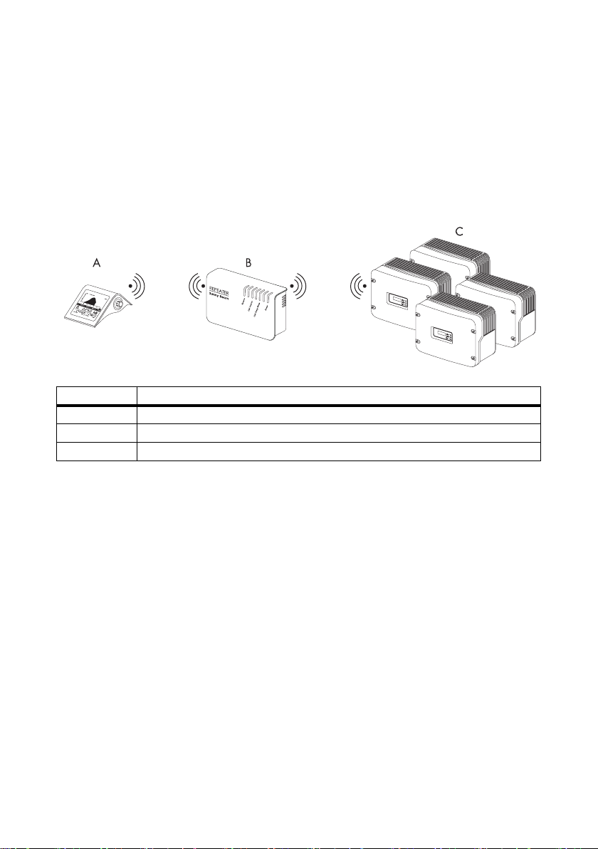
With the Sunny Beam Repeater, you can increase the Sunny Beam's range in order to reach the
inverters under problematic ambient conditions. The Sunny Beam Repeater can be simply integrated
into the existing transmission path from the Sunny Beam to the inverters. The Sunny Beam Repeater
requires a socket (AC 100 V to 240 V) for the power supply.
Position Description
ASunny Beam
B Sunny Beam Repeater
C inverters from SMA Solar Technology
2.2 Functions
Connection to the inverters and to the Sunny Beam via:
• Radio (up to 100 m in open air, up to 30 m in buildings, maximum 4 inverters)
Supported inverters:
• The Sunny Beam Repeater supports all inverters that the Sunny Beam supports.
Number of inverters supported:
•up to 4
Connection to the power supply via:
• USB plug-in power supply (max. 2 m)
Display of system states:
• via 4 light-emitting diodes
6 SBeamRep-BEN091911 User Manual
Page 7
SMA Solar Technology AG The Sunny Beam Repeater
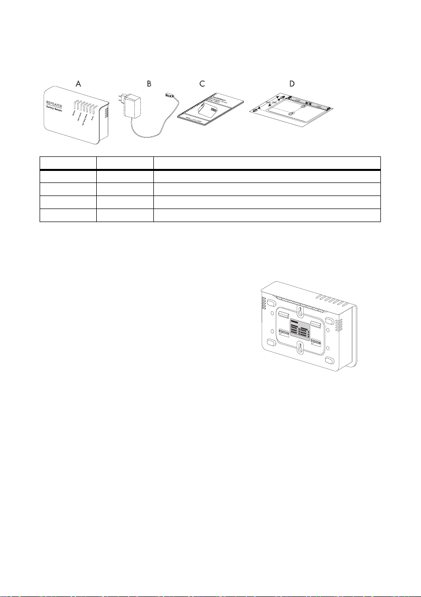
2.3 Scope of Delivery
Position Quantity Description
A 1 Sunny Beam Repeater
B 1 USB plug-in power supply
C 1 user manual
D 1 drilling Template
2.4 Identification
2.4.1 Type Plate
You can ide ntify t he Sunny Beam Re peater using t he type
plate. The type plate is located on the underside of the
Sunny Beam Repeater.
User Manual SBeamRep-BEN091911 7
Page 8
Safety Instructions SMA Solar Technology AG
3 Safety Instructions
Please follow all operating and safety instructions in this manual. Failure to follow these instructions
could result in damage to the device and cause personal injury.
DANGER!
Only use the Sunny Beam Repeater in a dry environment. Otherwise, there is a risk of
electric shock.
CAUTION!
The Sunny Beam Repeater must not be opened.
CAUTION!
Only use the plug-in power supply delivered with the Sunny Beam Repeater.
8 SBeamRep-BEN091911 User Manual
Page 9

SMA Solar Technology AG Determining the Installation Location
4 Determining the Installation Location
4.1 Requirements
Observe the following ambient conditions for the installation location of the Sunny Beam Repeater.
• The Sunny Beam Repeater is only suitable for the interior.
• Protect the Sunny Beam Repeater from dust, wet conditions, aggressive substances and vapors.
• The Sunny Beam Repeater requires socket (AC 100 V to 240 V) for the power supply.
• The ambient temperature must be between 0 °C and +55 °C.
4.2 Determination Procedure
1. Walk with the Sunny Beam into the range of the inverters and activate the Sunny Beam as
described in the Sunny Beam user manual. The inverters must be detected and registered with
the Sunny Beam.
Information
Group 15 may not be used in the Sunny Beam and the radio Piggy-Backs in case a Sunny
Beam Repeater is used.
Using group 15 can otherwise result in communication failures between the Sunny Beam
and the inverters.
2. Check that the inverters are operating.
3. Walk with the Sunny Beam until approximately three meters from the inverters (not closer).
4. Set the data request frequency to the maximum frequency (the minimum selectable interval) via
the menu "VIEW OPTIONS/DATA REQUEST FREQ.".
Information
It is important to set the data request frequency back to at le ast 15 seconds once you have
successfully determined the installation locations of the Sunny Beam Repeater and the
Sunny Beam. Lower values (under 15 seconds) should only be set for commissioning
purposes (testing the radio connection) and not long-term.
5. Go to the "SETUP/SERVICE/DIAGNOSTICS" menu.
User Manual SBeamRep-BEN091911 9
Page 10

Determining the Installation Location SMA Solar Technology AG
6. Here, you can read the communication quality (see figure below) which is calculated on the
basis of the ratio between the lost data packets and the sent data packets.
The r egistered inverters ar e listed with the last five digits o f the serial number. The foll owing values are
also specified:
"S"= data packets sent
"LS"= data packets lost on sending
"LR" = data packets lost on receipt
This is followed by the communication quality calculated in %.
The communication quality specifies the ratio between received and sent data packets of the
registered inverters. With a communication quality of 100 %, the signal strength is very good and no
data packets are lost.
DIAGNOSTICS
SBeam V2.21EU firmware
1.PB V:2.10 2.PB V:2. 04
3.PB V:0.00 4.PB V:0. 00
DEVICE S LS LR
.67890: 204 0 0 100%
.67891: 204 0 0 100%
3.07V
Communication quality in %
S
LR
LS
7. Move away with the Sunny Beam towards the desired installation location until the first data
packets are shown to be lost under LS or LR. Then move back towards the inverters again until
no more data packets are being lost.
8. Install the Sunny Beam Repeater at this location. First connect the provided USB power supply
to the Sunny Beam Repeater, then plug the power plug into a socket.
The Sunny Beam Repeater starts up.
All LEDs on the Sunny Beam Repeater briefly shine green. The Sunny Beam Repeater starts up.
This procedure takes approximately 1 minute.
9. In the Sunny Beam main menu, select "SETUP/PLANT"
and set a check mark beside the menu item
"REPEATER".
10. Select "EXIT" repeatedly until the prompt window
opens.
11. Select "Yes" in the prompt window. The setting is saved.
10 SBeamRep-BEN091911 User Manual
PLANT
Sunny Boy DETECTION
EXCLUDE Sunny Boys
GROUP
REPEATER :
EXIT
Page 11

SMA Solar Technology AG Determining the Installation Location
12. Return to the "SETUP/SERVICE/DIAGNOSTICS" menu.
DIAGNOSTICS
SBeam V2.21EU firmware
1.PB V:2.10 2.PB V:2.04
3.PB V:0.00 4.PB V:0.00
DEVICE S LS LR
.67890: 204 0 0 100%
.67891: 204 0 0 100%
3.07V
Communication quatlity
in %
13. You can now walk away with the Sunny Beam towards the desired installation location until the
communication quality is still at least 50 %.
14. If you have reached the desired installation location with sufficient communication quality,
commissioning is successfully completed at this point.
Set the data request frequency back to a value of at least 15 seconds or higher via the menu
"VIEW OPTIONS/DATA REQUEST FREQ.".
15. If you cannot yet reach the desired installation location with sufficient communication quality,
change the installation location of the Sunny Beam Repeater. Even altering the position by only
a few meters may improve the communication quality.
16. After successful commissioning, set the data request frequency back to a value of at least 15
seconds or higher via the menu "VIEW OPTIONS/DATA REQUEST FREQ.".
User Manual SBeamRep-BEN091911 11
Page 12

Determining the Installation Location SMA Solar Technology AG
From Building to Building
If the radio connection from building to building is insufficient due to the buildings being too far apart,
or because of excessive attenuation, you can use the Sunny Beam Repeater to bridge a transmission
gap, or to improve a poor radio connection.
Transmission gap (without Sunny Beam Repeater)
Bridging the transmission gap (with the Sunny Beam Repeater)
12 SBeamRep-BEN091911 User Manual
Page 13

SMA Solar Technology AG Determining the Installation Location
From Floor to Floor
If the radio connection within a building is insufficient due to the devices being too far apart, or
because of excessive attenuation through ceilings and walls, you can use the Sunny Beam Repeater
to bridge a transmission gap, or to improve a poor radio connection.
Transmission gap
(without Sunny Beam Repeater)
User Manual SBeamRep-BEN091911 13
Bridging the transmission gap
(with Sunny Beam Repeater)
Page 14

Determining the Installation Location SMA Solar Technology AG
From Building to Building with an External Antenna Kit
You can also use the Sunny Beam Repeater in conjunction with the external antenna kit from SMA
Solar Technology. The external antenna kit is intended for the installation on the inverter.
With the external antenna kit, comprising an antenna bracket and extension cable, you can bridge
walls or ceilings.
Transmission gap (without Sunny Beam Repeater)
Bridging the transmission gap (with the Sunny Beam Repeater)
14 SBeamRep-BEN091911 User Manual
Page 15

SMA Solar Technology AG Determining the Installation Location
From Floor to Floor with an External Antenna Kit
You can also extend the external antenna kit with the Sunny Beam Repeater within a building. You
can bridge walls and ceilings with the external antenna kit. With the Sunny Beam Repeater, you can
then bridge any transmission gap that may still exist.
Transmission gap
(without Sunny Beam Repeater)
User Manual SBeamRep-BEN091911 15
Bridging the transmission gap
(with Sunny Beam Repeater)
Page 16

Installation SMA Solar Technology AG
5 Installation
Information
Only install the Sunny Beam Repeater once you have determined the appropriate
installation location as described in section 4 "Determining the Installation Location"
(page9).
The Sunny Beam Repeater can be used as a tabletop or wall-mounted device. If you choose to mount
the device on a wall, you can either mount it directly on the wall or on top hat rails.
5.1 Tabletop Device
If you use the Sunny Beam Repeater as a tabletop device, follow the points below:
• Do not cover the Sunny Beam Repeater. This can cause heat to accumulate in the device.
• Lay t he USB powe r supply ca ble in such a manner th at its weigh t does not cause it to disconnect.
• Lay the cable properly so that there is no risk of persons tripping over it.
16 SBeamRep-BEN091911 User Manual
Page 17

SMA Solar Technology AG Installation
5.2 Wall Mounting
Mounting accessories provided
Position Quantity Description
A 1 drilling template
1. Pull the USB power supply plug out of the socket.
2. Pull the USB plug out of the Sunny Beam Repeater.
3. Use the provided drilling template to determine the position of the Sunny Beam Repeater on the
wall. Observe the USB power supply's cable length.
4. Mark the position of the drill holes.
5. Drill the holes and install the screws. Use screws with a shank diameter of 3.5 mm to 4.5 mm
(e. g. 4.5 mm x 60 mm).
6. Leave about 6 mm clearance between the screw head and the wall.
7. Hang the Sunny Beam Repeater on the screws (see figure).
8. Plug the USB power s upply's USB plu g into the socke t on the lower
edge of the housing of the Sunny Beam Repeater.
9. Then plug the USB power supply's plug into the socket.
All LEDs on the Sunny Beam Repeater briefly shine green. The
Sunny Beam Repeater starts up. This procedure takes
approximately 1 minute.
5.3 Top Hat Rail Installation
1. Pull the USB power supply plug out of the socket.
User Manual SBeamRep-BEN091911 17
Page 18

Installation SMA Solar Technology AG
2. Pull the USB plug out of the Sunny Beam Repeater.
3. Fasten a top hat rail onto the wall. Observe the USB power supply's cable length.
4. Hook both lower retainers of the repeater under the lower edge of the top hat rail.
5. Push the repeater upwards.
6. Hook the repeater's two upper catches over the upper edge of the top hat rail.
18 SBeamRep-BEN091911 User Manual
Page 19

SMA Solar Technology AG Explanation of the LEDs
6 Explanation of the LEDs
The repeater has 4 LEDs, with which the status of the device can be ascertained. The repeater is
equipped with the following LEDs:
• Receive
• Link Inverter (connection to the inverter)
• Link Sunny Beam (connection to the Sunny Beam)
•Power (power supply)
This section explains the repeater's various light signals and flash signals.
LED Status/Color Display
Receive flashes orange Data are being received.
off No data are being received.
Link Inverter shines orange The repeater has received data from the inverter.
off The repeater is not receiving any data from the
inverter.
Link Sunny Beam shines orange The repeater has received data from the Sunny
Beam.
off The repeater is not receiving any data from the
Sunny Beam.
Power shines green The power supply is ok.
off (All LEDs are off), no power supply is present.
User Manual SBeamRep-BEN091911 19
Page 20

Maintenance and Cleaning SMA Solar Technology AG
7 Maintenance and Cleaning
7.1 Maintenance
The repeater does not require maintenance.
7.2 Cleaning
ATTENTION!
Damage to the device due to penetration of liquids.
The repeater is not waterproof, liquids should not be allowed to penetrate.
• To clean the device, use only a lightly dampened cloth so as to prevent the
penetration of liquids. If there is a considerable amount of dirt, you can also use a
mild, non-abrasive and non-corrosive cleaning agent.
8 Decommissioning
8.1 Disassembly
Pull the USB plug-in power supply's plug out of the socket. Then pull the USB plug out of the repeater.
8.2 Packaging for Shipment
When returning the device to us, be sure to use packaging which adequately protects the device from
damage during transport (if possible, the original packaging).
8.3 Disposal
Dispose of the repeater at an authorized disposal company.
20 SBeamRep-BEN091911 User Manual
Page 21

SMA Solar Technology AG Technical Data
9 Technical Data
Dimensions
Size 225 mm x 130 mm x 57 mm (width x height x depth)
Vertically, the repeater requires an additional space of
approximately 15 cm for the cable.
Weight 750 g
Power supply
USB plug-in power supply input voltage 100 V to 240 V
47 Hz to 63 Hz
output voltage 5 V
Environmental conditions for operation
Ambient temperature 0 °C to +55 °C
Relative humidity 5 % to 95 %, non-condensing
Protection rating IP20
Warranty, Certificates aund Permits
www.SMA.de
User Manual SBeamRep-BEN091911 21
Page 22

Contact SMA Solar Technology AG
10 Contact
If you have technical problems concerning our products, contact the SMA Service Line. We need the
following information in order to provide you with the necessary assistance:
• Type of inverters and serial numbers
• Serial number of the repeater
• Serial number and firmware version of the Sunny Beam
SMA Solar Technology AG
Sonnenallee 1
34266 Niestetal, Germany
www.SMA.de
Service Line
Inverters: +49 561 9522 1499
Communication: +49 561 9522 2499
Fax: +49 561 9522 4699
E-Mail: serviceline@SMA.de
22 SBeamRep-BEN091911 User Manual
Page 23

SMA Solar Technology AG Legal Restrictions
The information contained in this document is the property of SMA Solar Technology AG. Publishing its content, either partially or
in full, requires the written permission of SMA Solar Technology AG. Any internal company copying of the document for the
purposes of evaluating the product or its correct implementation is allowed and does not require permission.
Exclusion of liability
The general terms and conditions of delivery of SMA Solar Technology AG shall apply.
The content of these documents is continually checked and amended, where necessary. However, discrepancies cannot be
excluded. No guarantee is made for the completeness of these do cuments. The latest version is available online at www.SMA.de
or from the usual sales channels.
Guarantee or liability claims for damages of any kind are excluded if they are caused by one or more of the following:
• Damages during transportation
• Improper or inappropriate use of the product
• Operating the product in an unintended environment
• Operating the product whilst ignoring relevant, statutory safety regulations in the deployment location
• Ignoring safety warnings and instructions contained in all documents relevant to the product
• Operating the product under incorrect safety or protection conditions
• Altering the product or supplied software without authority
• The product malfunctions due to operating attached or neighboring devices beyond statutory limit values
• In case of unforeseen calamity or force majeure
The use of supplied software produced by SMA Solar Technology AG is subject to the following conditions:
• SMA Solar Technology AG rejects any liability for direct or indirect damages arising from the use of software developed by
SMA Solar Technology AG. This also applies to the provision or non-provision of support activities.
• Supplied software not developed by SMA Solar Technology AG is subject to the respective licensing and liability agreements
of the manufacturer.
SMA Factory Warranty
The current guarantee conditions come enclosed with your device. These are also available online at www.SMA.de and can be
downloaded or are available on paper from the usual sales channels if required.
Trademarks
All trademarks are recognized even if these are not marked separately. Missing designations do not mean that a product or brand
is not a registered trademark.
The Bluetooth
Solar Technology is under license.
SMA Solar Technology AG
Sonnenallee 1
34266 Niestetal
Germany
Tel. +49 561 9522-0
Fax +49 561 9522-100
www.SMA.de
E-Mail: info@SMA.de
© 2004 to 2009 SMA Solar Technology AG. All rights reserved
®
wor d mark an d logos are registe red trad emar ks own ed by Blu etoo th SIG, I nc. and a ny use of su ch marks by SMA
User Manual SBeamRep-BEN091911 23
Page 24

SMA Solar Technology AG
www.SMA.de
 Loading...