

Page 1
Operating Manual
BATFUSE-B.01 / B.03
BatFuse-BE-en-30 | Version 3.0 ENGLISH
Page 2

Legal Provisions SMA Solar Technology AG
Legal Provisions
The information contained in this document is the property of SMA Solar Technology AG. Publishing
its content, either partially or in full, requires the written permission of SMA Solar Technology AG.
Any internal company copying of the document for the purposes of evaluating the product or its
correct implementation is allowed and does not require permission.
SMA Warranty
You can download the current warranty conditions from the Internet at www.SMA-Solar.com.
Trademarks
All trademarks are recognized, even if not explicitly identified as such. A lack of identification does
not mean that a product or symbol is not trademarked.
The BLUETOOTH
and any use of these marks by SMA Solar Technology AG is under license.
Modbus® is a registered trademark of Schneider Electric and is licensed by the Modbus
Organization, Inc.
QR Code is a registered trademark of DENSO WAVE INCORPORATED.
®
Phillips
and Pozidriv® are registered trademarks of Phillips Screw Company.
®
Torx
is a registered trademark of Acument Global Technologies, Inc.
SMA Solar Technology AG
Sonnenallee 1
34266 Niestetal
Germany
Tel. +49 561 9522-0
Fax +49 561 9522-100
www.SMA.de
E-mail: info@SMA.de
© 2004 to 2014 SMA Solar Technology AG. All rights reserved.
®
word mark and logos are registered trademarks owned by Bluetooth SIG, Inc.
2 BatFuse-BE-en-30 Operating Manual
Page 3

SMA Solar Technology AG Table of Contents
Table of Contents
1 Information on this Document. . . . . . . . . . . . . . . . . . . . . . . . . . . 5
1.1 Validity. . . . . . . . . . . . . . . . . . . . . . . . . . . . . . . . . . . . . . . . . . . . . . . . . 5
1.2 Target Group. . . . . . . . . . . . . . . . . . . . . . . . . . . . . . . . . . . . . . . . . . . . 5
1.3 Symbols. . . . . . . . . . . . . . . . . . . . . . . . . . . . . . . . . . . . . . . . . . . . . . . . 5
2 Safety . . . . . . . . . . . . . . . . . . . . . . . . . . . . . . . . . . . . . . . . . . . . . . 6
2.1 Intended Use . . . . . . . . . . . . . . . . . . . . . . . . . . . . . . . . . . . . . . . . . . . . 6
2.2 Skills of Qualified Persons . . . . . . . . . . . . . . . . . . . . . . . . . . . . . . . . . . 7
2.3 Safety Precautions . . . . . . . . . . . . . . . . . . . . . . . . . . . . . . . . . . . . . . . . 7
3 Scope of Delivery . . . . . . . . . . . . . . . . . . . . . . . . . . . . . . . . . . . . . 8
4 Product Description . . . . . . . . . . . . . . . . . . . . . . . . . . . . . . . . . . . 9
4.1 BatFuse . . . . . . . . . . . . . . . . . . . . . . . . . . . . . . . . . . . . . . . . . . . . . . . . 9
4.2 Type Label . . . . . . . . . . . . . . . . . . . . . . . . . . . . . . . . . . . . . . . . . . . . . 10
5 Transport and Mounting . . . . . . . . . . . . . . . . . . . . . . . . . . . . . . 11
5.1 Transport . . . . . . . . . . . . . . . . . . . . . . . . . . . . . . . . . . . . . . . . . . . . . . 11
5.2 Mounting the BatFuse . . . . . . . . . . . . . . . . . . . . . . . . . . . . . . . . . . . . 11
6 Electrical Connection . . . . . . . . . . . . . . . . . . . . . . . . . . . . . . . . . 13
6.1 Connection Area . . . . . . . . . . . . . . . . . . . . . . . . . . . . . . . . . . . . . . . . 13
6.2 Connecting the Sunny Island. . . . . . . . . . . . . . . . . . . . . . . . . . . . . . . 14
6.3 Connecting the Sunny Island Charger. . . . . . . . . . . . . . . . . . . . . . . . 15
6.4 Connecting Loads to the Battery Voltage Tap . . . . . . . . . . . . . . . . . . 16
6.5 Connecting the Battery . . . . . . . . . . . . . . . . . . . . . . . . . . . . . . . . . . . 17
7 Commissioning the BatFuse. . . . . . . . . . . . . . . . . . . . . . . . . . . . 18
8 Replacing the Fuse Link . . . . . . . . . . . . . . . . . . . . . . . . . . . . . . . 19
9 Decommissioning the BatFuse. . . . . . . . . . . . . . . . . . . . . . . . . . 20
10 Technical Data . . . . . . . . . . . . . . . . . . . . . . . . . . . . . . . . . . . . . . 21
10.1 Fuse . . . . . . . . . . . . . . . . . . . . . . . . . . . . . . . . . . . . . . . . . . . . . . . . . . 21
10.2 Electrical Data . . . . . . . . . . . . . . . . . . . . . . . . . . . . . . . . . . . . . . . . . . 21
Operating Manual BatFuse-BE-en-30 3
Page 4

Table of Contents SMA Solar Technology AG
10.3 Battery Terminals . . . . . . . . . . . . . . . . . . . . . . . . . . . . . . . . . . . . . . . . 21
10.4 Sunny Island Charger Terminals . . . . . . . . . . . . . . . . . . . . . . . . . . . . 21
10.5 Sunny Island Terminals . . . . . . . . . . . . . . . . . . . . . . . . . . . . . . . . . . . 22
10.6 Battery Voltage Tap Terminal . . . . . . . . . . . . . . . . . . . . . . . . . . . . . . 22
10.7 Mechanical Data. . . . . . . . . . . . . . . . . . . . . . . . . . . . . . . . . . . . . . . . 22
10.8 Ambient Conditions . . . . . . . . . . . . . . . . . . . . . . . . . . . . . . . . . . . . . . 22
10.9 General Data. . . . . . . . . . . . . . . . . . . . . . . . . . . . . . . . . . . . . . . . . . . 22
11 Contact . . . . . . . . . . . . . . . . . . . . . . . . . . . . . . . . . . . . . . . . . . . . 23
4 BatFuse-BE-en-30 Operating Manual
Page 5
SMA Solar Technology AG 1 Information on this Document
1 Information on this Document
1.1 Validity
This document is valid for the following device types:
• BatFuse-B.01
• BatFuse-B.03
1.2 Target Group
This document is intended for qualified persons. Only persons with the appropriate skills are allowed
to perform the activities described in this document (see Section2.2 "Skills of Qualified Persons",
page7).
1.3 Symbols
The following types of safety precautions and general information appear in this document:
Symbol Explanation
Indicates a hazardous situation which, if not avoided, will result in death or
serious injury
Indicates a hazardous situation which, if not avoided, can result in death or
serious injury
Indicates a hazardous situation which, if not avoided, can result in minor or
moderate injury
Indicates a situation which, if not avoided, can result in property damage
Information that is important for a specific topic or goal, but is not
safety-relevant
☐ Indicates a requirement for meeting a specific goal
☑ Desired result
✖ A problem that might occur
Operating Manual BatFuse-BE-en-30 5
Page 6
2 Safety SMA Solar Technology AG
2 Safety
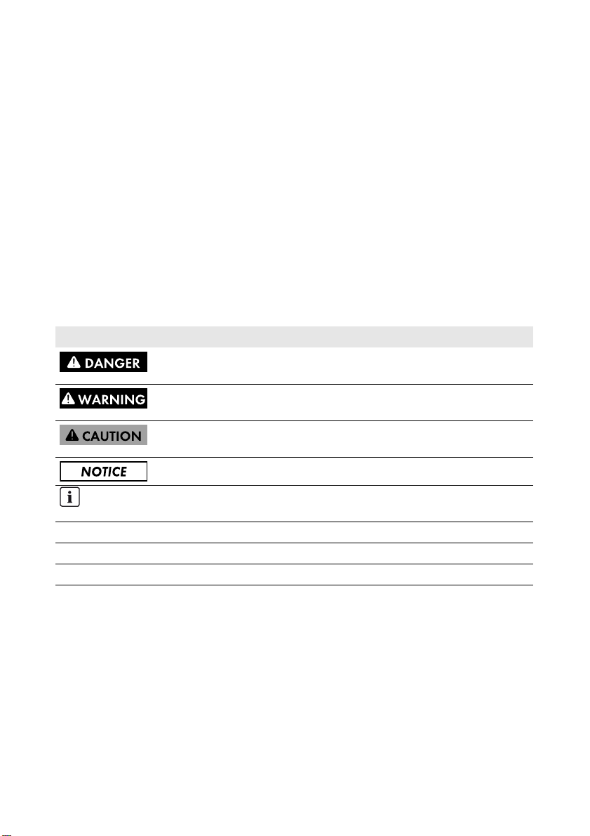
2.1 Intended Use
The BatFuse is a battery fuse box that acts as a DC fuse by protecting the DC cables of the
Sunny Island. The BatFuse-B.01 is designed for connecting no more than one Sunny Island and
BatFuse-B.03 is designed for connecting a maximum of three Sunny Island inverters.
Figure1: Principle of a Sunny Island system with a BatFuse
The BatFuse is designed for indoor use only.
The conductors of all connection cables must be made of copper.
Us e th is p rod uct onl y in acc ord anc e wi th t he i nfo rma tio n pr ovi ded in the enclosed documentation and
with the loc ally applicable standards and dire ctives. Any other application may cause personal injury
or property damage.
Alterations to the p roduct, e.g. mod ification s or con versions, are only allowed with the exp ress wr itten
permission of SMA Solar Technology AG. Unauthorized changes will void the warranty and is likely
to result in invalidation of the operating permit. SMA Solar Technology AG shall not be held liable
for any damage caused by such changes.
6 BatFuse-BE-en-30 Operating Manual
Page 7
SMA Solar Technology AG 2 Safety
Any use of the product other than described in the Intended Use section does not qualify as
appropriate.
The enclosed documentation is an integral part of this product. Keep the documentation in a
convenient place for future reference and observe all instructions contained therein.
The type label must remain permanently attached to the product.
2.2 Skills of Qualified Persons
Qualified persons must have the following skills:
• Training in off-grid systems from SMA Solar Technology AG
• Training in how to deal with the dangers and risks associated with installing and operating
electrical devices and batteries
• Training in the installation and commissioning of electrical devices
• Knowledge of and adherence to the local standards and directives
• Knowledge of and compliance with this document and all safety precautions
2.3 Safety Precautions
This section contains safety precautions that must be observed at all times when working on or with
the product.
To prevent personal injury and property damage and to ensure long-term operation of the product,
read this section carefully and follow all safety precautions at all times.
Risk of injury due to short-circuit currents
Short-circuit currents in the battery can cause heat build-up and electric arcs. Burns or eye injuries
due to flashes may result.
• Follow all safety and maintenance instructions provided by the battery manufacturer.
• Remove watches, rings and other metal objects.
•Use insulated tools.
• Do not place tools or metal parts on the battery.
• When working on the installation, make sure that all DC cables have been removed from the
pole connections of the battery and that the BatFuse is voltage-free.
• Make sure that the polarity of the cables to the battery is correct.
• Make sure that the mechanical connection at the terminals is tight.
• Open the load-break switch quickly and then close it.
• Ensure that the enclosure lid of the BatFuse is closed when the load-break switch is closed.
Operating Manual BatFuse-BE-en-30 7
Page 8
3 Scope of Delivery SMA Solar Technology AG
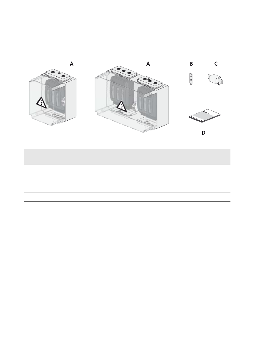
3 Scope of Delivery
Check the scope of delivery for completeness and any externally visible damage. Contact your
distributor if the scope of delivery is incomplete or damaged.
Figure2: Components included in the scope of delivery
Position Quantity for
BatFuse-B.01
Quantity for
BatFuse-B.03
Designation
A 1 1 BatFuse
B 4 4 Anchorage brackets for wall mounting
C 2 6 Spare fuses LV/HRC size 1
D 1 1 Operating manual
8 BatFuse-BE-en-30 Operating Manual
Page 9
SMA Solar Technology AG 4 Product Description
4 Product Description
4.1 BatFuse
The BatFuse is a battery fuse box that acts as a DC fuse by protecting the DC cables of the
Sunny Island. The BatFuse enables disconnection on the DC side.
The BatFuse serves as DC busbar for the installation of the Sunny Island Charger.
The BatFuse is available with various fuse links for the different power classes of the Sunny Island
inverters.
Fuse Links of the BatFuse-B.01 for a Maximum of One Sunny Island
Device type Sunny Island Recommended fuse link
Sunny Island 3.0M 80 A
Sunny Island 4.4M 100 A
Sunny Island 6.0H 160 A
Sunny Island 8.0H 200 A
Sunny Island 5048 250 A
Fuse Links of the BatFuse-B.03 for a Maximum of Three Sunny Island Inverters
Device type Sunny Island Recommended fuse link
Sunny Island 3.0M 80 A
Sunny Island 4.4M 100 A
Sunny Island 6.0H 160 A
Sunny Island 8.0H 200 A
Sunny Island 5048 250 A
The BatFuse features a battery voltage tap to which the following loads can be connected:
• Sunny Island load-shedding contactor
• DC-to-DC converter for supplying a Sunny WebBox, a Sunny Boy Control or a battery room fan
The battery voltage tap guarantees an interruption-free supply of the connected loads when the AC
grid is switched off or under fault conditions.
Operating Manual BatFuse-BE-en-30 9
Page 10

4 Product Description SMA Solar Technology AG
4.2 Type Label
The type label clearly identifies the product.
You will find the following information on the type label:
• Manufacturer contact information
• Device type (Model)
•Serial number (Serial No.)
• Device-specific characteristics
Yo u wi ll r equ ire the inf ormatio n on the typ e la bel to u se t he p roduct safely and when seeking customer
support from the SMA Service Line.
Symbols on the Type Label
Symbol Explanation
Danger to life due to high voltages
The product operates at high voltages. All work on the product must be
carried out by qualified persons only.
Risk of burns due to hot surfaces
The product can get hot during operation. Avoid contact during operation.
Allow the product to cool down sufficiently before carrying out any work.
Wear personal protective equipment such as safety gloves.
Observe the documentation.
Observe all documentation supplied with the product.
WEEE designation
Do not dispose of the product together with the household waste but in
accordance with the locally applicable disposal regulations for electronic
waste.
CE marking
The product complies with the requirements of the applicable EU directives.
Degree of protection
The product is protected against dust intrusion and water jets from any angle.
10 BatFuse-BE-en-30 Operating Manual
Page 11

SMA Solar Technology AG 5 Transport and Mounting
5 Transport and Mounting
5.1 Transport
There are no special requirements for transport. The BatFuse can be transported without any aids.
5.2 Mounting the BatFuse
Requirements for the mounting location:
☐ The BatFuse must be mounted on a stable support surface, e.g. concrete, walls.
☐ The mounting location must be suitable for the weight and dimensions of the BatFuse
(see Section10 "Technical Data", page21).
☐ The mounting location must be clear and safely accessible at all times without the need for any
auxiliary equipment (e.g. scaffolding or lifting platforms).
☐ The mounting location must not hinder access to disconnection devices.
☐ Above and below the BatFuse, a clearance of 300 mm to walls, other devices or objects must
be maintained.
☐ The mounting wall must be vertical.
☐ The climatic conditions must be met to ensure proper operation (see Section10.8 "Ambient
Conditions", page22).
Dimensions for wall mounting:
Figure3: Dimensions of the drill holes
Operating Manual BatFuse-BE-en-30 11
Page 12

5 Transport and Mounting SMA Solar Technology AG
Additionally required mounting material (not included in the scope of delivery):
☐ At least four screws that are suitable for the support surface
☐ At least four washers that are suitable for the screws
☐ If necessary, at least four screw anchors suitable for the support surface and the screws
Danger to life due to fire or explosion
Despite careful construction, electrical devices can cause fire.
• Do not mount the BatFuse on flammable construction materials.
• Do not mount the BatFuse near highly flammable materials.
• Do not mount the BatFuse in potentially explosive areas.
Procedure:
1. Ensure that no cables are laid in the wall which could be damaged when drilling holes.
2. Attach the anchorage brackets either vertically,
horizontally or diagonally on the rear panel of the
BatFuse.
3. Mark the position of the drill holes at the mounting location.
4. Drill the holes.
5. Insert screw anchors into the drill holes if necessary.
6. Fasten the BatFuse with at least four suitable screws and the anchorage brackets.
7. Ensure that the BatFuse is firmly attached.
12 BatFuse-BE-en-30 Operating Manual
Page 13

SMA Solar Technology AG 6 Electrical Connection
6 Electrical Connection
6.1 Connection Area
Figure4: Connection area of the BatFuse
Position Designation Explanation
A Inverter side Terminal for Sunny Island
B Battery voltage tap Terminals for loads
C Battery side Terminal for battery and
Sunny Island Charger
Terminals Inverter Side (A)
BatFuse-B.01 BatFuse-B.03
Number of components to be
connected
External diameter of cables for
the Sunny Island
Terminal lug M8, maximum width: 25 mm M8, maximum width: 25 mm
Operating Manual BatFuse-BE-en-30 13
One Sunny Island A maximum of three
Sunny Island inverters
14 mm to 21 mm 14 mm to 21 mm
Page 14

6 Electrical Connection SMA Solar Technology AG
Terminals Battery Side (C)
BatFuse-B.01 BatFuse-B.03
Number of components to be
connected
External diameter of cables for
One battery and a maximum of
two Sunny Island Charger
devices
One battery and a maximum of
four Sunny Island Charger
devices
1 x 14 mm to 21 mm 2 x 14 mm to 21 mm
the battery
External diameter of cables for
9 mm to 16 mm 9 mm to 16 mm
the Sunny Island Charger
Terminal lug M8, maximum width: 25 mm M8, maximum width: 25 mm
6.2 Connecting the Sunny Island
Figure5: Overview of terminals
Position Designation
ATerminal L+
BTerminal L−
Cable requirements:
☐ Conductor cross-section: specified by the Sunny Island
☐ External diameter: 14 mm to 21 mm
☐ Material of the conductor: copper
☐ Terminal lugs size M8, maximum width: 25 mm
Procedure:
1. Loosen the four screws of the enclosure lid.
2. Remove the enclosure lid of the BatFuse.
3. Open the load-break switch and remove it from the support.
4. Remove the cover.
5. Mount the terminal lugs on the DC+ cable and on the DC − cable of the Sunny Island.
14 BatFuse-BE-en-30 Operating Manual
Page 15

SMA Solar Technology AG 6 Electrical Connection
6. On the inverter side, pierce the double-membrane seals with the larger diameter from the
outside with a sharp object.
7. Lead the DC+ cable of the Sunny Island through the double-membrane seal into the BatFuse
and connect it to terminal L+ (torque: 4.0 Nm to 5.7 Nm).
8. Lead the DC − cable of the Sunny Island through the double-membrane seal into the BatFuse
and connect it to terminal L− (torque: 4.0 Nm to 5.7 Nm).
6.3 Connecting the Sunny Island Charger
Figure6: Overview of terminals
Position Designation
ATerminal L+
BTerminal L−
Cable requirements:
☐ Maximum conductor cross-section: 16 mm²
☐ External diameter: 9 mm to 16 mm
☐ Terminal lugs of size M8, maximum width: 16 mm
☐ Material of the conductor: copper
Procedure:
1. Mount the terminal lugs on the DC+ cable and on the DC − cable of the Sunny Island.
2. On the battery side, pierce the double-membrane seals with the smaller diameter with a sharp
object from the outside.
3. Lead the DC+ cable of the Sunny Island Charger
devices through the double-membrane seals into
the BatFuse and connect it to terminal L+
(torque: 4.0 Nm to 5.7 Nm). Always connect two
Sunny Island Charger devices to one terminal.
4. Lead the DC − cable of the Sunny Island Charger
devices through the double-membranes seal into
the BatFuse and connect it to terminal L− (torque: 4.0 Nm to 5.7 Nm). Always connect two
Sunny Island Charger devices to one terminal.
Operating Manual BatFuse-BE-en-30 15
Page 16

6 Electrical Connection SMA Solar Technology AG
6.4 Connecting Loads to the Battery Voltage Tap
Figure7: Overview of terminals
Position Designation
ATerminal L+
BTerminal L−
Requirements:
☐ Electrical current strength: maximum 8 A
☐ Maximum conductor cross-section: 6 mm²
☐ External diameter of the cable: 9 mm to 16 mm
☐ Material of the conductor: copper
Procedure:
1. Mount the terminal lugs on the DC+ cable and on the DC − cable of the load.
2. On the inverter side, pierce the double-membrane seals with the smaller diameter with a sharp
object from the outside.
3. Lead the cable of the load through the double-membrane seal into the BatFuse and connect it
to terminals L+ and L− on the battery voltage tap (torque: 4.0 Nm to 5.7 Nm).
16 BatFuse-BE-en-30 Operating Manual
Page 17

SMA Solar Technology AG 6 Electrical Connection
6.5 Connecting the Battery
Figure8: Overview of terminals
Position Designation
ATerminal L+
BTerminal L−
Cable requirements:
☐ Maximum conductor cross-section: 95 mm²
☐ External diameter: 14 mm to 21 mm
☐ Material of the conductor: copper
☐ Terminal lugs of size M8, maximum width: 25 mm
Procedure:
1. Ensure that the DC − cables are free of voltage and not connected to any pole of the battery.
2. Mount the terminal lugs on the DC+ and on the DC − cable.
3. On the battery side, pierce the double-membrane seals (having the larger diameter) with a
sharp object from the outside.
4. Lead the DC+ cable of the battery through the double-membrane seal into the BatFuse and
connect it to terminal L+ on the battery side (torque: 4.0 Nm to 5.7 Nm).
5. Lead the DC − cable of the battery through the double-membrane seal into the BatFuse and
connect it to terminal L− on the battery side (torque: 4.0 Nm to 5.7 Nm).
6. Insert the cover.
Operating Manual BatFuse-BE-en-30 17
Page 18

7 Commissioning the BatFuse SMA Solar Technology AG
7 Commissioning the BatFuse
Risk of injury due to short-circuit currents
Short-circuit currents in the battery can cause heat build-up and electric arcs. Burns or eye injuries
due to flashes may result.
• Follow all safety and maintenance instructions provided by the battery manufacturer.
• Make sure that the BatFuse load-break switch is only closed once the system is being
commissioned.
• Remove watches, rings and other metal objects.
•Use insulated tools.
• Do not place tools or metal parts on the battery.
• Make sure that the polarity of the cables to the battery is correct.
• Make sure that the mechanical connection at the terminals is tight.
Procedure:
1. Make sure that all installation work has been completed and that all live components are
protected from being touched.
2. Connect the DC cables to the battery (see documentation of the battery manufacturer).
3. Select fuse links (see Section4 "Product Description", page9) and insert them into the
load-break switch.
4. Attach the load-break switch to the support and close it quickly.
5. Close the enclosure lid of the BatFuse.
18 BatFuse-BE-en-30 Operating Manual
Page 19

SMA Solar Technology AG 8 Replacing the Fuse Link
8 Replacing the Fuse Link
1. Remove the enclosure lid of the BatFuse.
2. Open the load-break switch.
3. Push th e interl ock on the fu se h older d own and slide
the defective fuse link out of the fuse holder.
4. Put a new fuse link into the holder and slide it in.
☑ The fuse link snaps audibly into place.
5. Ensure that the correct fuse link is plugged into the
fuse holder (see Section4.1 "BatFuse", page9).
6. Close the load-break switch quickly.
7. Close the enclosure lid of the BatFuse.
Operating Manual BatFuse-BE-en-30 19
Page 20

9 Decommissioning the BatFuse SMA Solar Technology AG
9 Decommissioning the BatFuse
Risk of injury due to short-circuit currents
Short-circuit currents in the battery can cause heat build-up and electric arcs. Burns or eye injuries
due to flashes may result.
• Follow all safety and maintenance instructions provided by the battery manufacturer.
• Remove watches, rings and other metal objects.
•Use insulated tools.
• Do not place tools or metal parts on the battery.
Procedure:
1. Switch off the Sunny Island system.
2. Open all circuit breakers of the Sunny Island devices and secure against reconnection.
3. Open the cir cui t bre ake rs o f the Sun ny Is lan d Ch arg er d evi ces and secure against reconnection.
4. Loosen the four screws of the BatFuse enclosure lid.
5. Remove the enclosure lid and open the load-break switch.
6. Remove the DC − cables on the battery side. Use insulated tools.
7. Make sure that all terminals of the BatFuse are voltage-free.
8. Remove the cover.
9. Remove all cables from the BatFuse.
10. Insert the cover and close the BatFuse enclosure lid.
11. Loosen the fastening screws of the BatFuse and take down the BatFuse.
12. If the BatFuse is to be stored or shipped in packaging, pack the BatFuse. Use the original
packaging or packaging that is suitable for the weight and dimensions of the BatFuse.
13. If the BatFuse is to be disposed of, observe the locally applicable disposal regulations for
electronic waste.
20 BatFuse-BE-en-30 Operating Manual
Page 21

SMA Solar Technology AG 10 Technical Data
10 Technical Data
10.1 Fuse
BatFuse-B.01 BatFuse-B.03
Type LV/HRC size 1 LV/HRC size 1
Approved fuse links 80 A to 250 A 80 A to 250 A
Support Fuse-switch-disconnector Fuse-switch-disconnector
Quantity 2 6
10.2 Electrical Data
Rated voltage 12 V / 24 V / 48 V
Rated current depending on fuse link 80 A / 100 A / 160 A / 200 A / 250 A
Rated voltage of the battery voltage tap 12 V / 24 V / 48 V
Rated current for battery voltage tap 8 A
10.3 Battery Terminals
BatFuse-B.01 BatFuse-B.03
Number of terminals 1 2
Terminal lug M8 M8
Maximum width of the terminal lug 25 mm 25 mm
Maximum conductor cross-section 95 mm² 95 mm²
External diameter of cables 14 mm to 21 mm 14 mm to 21 mm
10.4 Sunny Island Charger Terminals
BatFuse-B.01 BatFuse-B.03
Number of terminals 2 4
Terminal lug M8 M8
Maximum width of the terminal lug 16 mm 16 mm
Maximum conductor cross-section 4x16 mm² 8x16 mm²
External diameter of cables 4 x 9 mm to 16 mm 8 x 9 mm to 16 mm
Operating Manual BatFuse-BE-en-30 21
Page 22

10 Technical Data SMA Solar Technology AG
10.5 Sunny Island Terminals
BatFuse-B.01 BatFuse-B.03
Number of terminals 1 3
Terminal lug M8 M8
Maximum width of the terminal lug 25 mm 25 mm
Maximum conductor cross-section 95 mm² 95 mm²
External diameter of cables 14 mm to 21 mm 14 mm to 21 mm
10.6 Battery Voltage Tap Terminal
Number of terminals 1
Maximum conductor cross-section 6 mm²
External diameter of the cable 9 mm to 16 mm
Cylindrical fuse 2 x 8 A
10.7 Mechanical Data
BatFuse-B.01 BatFuse-B.03
Width x height x depth 250 mm x 375 mm x 150 mm 500 mm x 375 mm x 225 mm
Weight 7 kg 16 kg
10.8 Ambient Conditions
Operating temperature range − 20°C to + 60°C
Maximum moisture, no condensation 100%
10.9 General Data
Degree of protection as per IEC 60529 IP65
Assembly Wall mounting
Certificates and approvals www.SMA-Solar.com
22 BatFuse-BE-en-30 Operating Manual
Page 23

SMA Solar Technology AG 11 Contact
11 Contact
If you have technical problems with our products, contact the SMA Service Line. We require the
following information in order to provide you with the necessary assistance:
•Type of BatFuse
• BatFuse serial number
• Type and number of connected Sunny Island inverters
• Type of battery connected
• Nominal battery capacity
• Nominal battery voltage
• Number of connected Sunny Island Chargers
• Loads connected to the battery voltage tap
Australia SMA Australia Pty Ltd.
Sydney
Belgien/
Belgique/
België
Brasil Vide España (Espanha)
Česko SMA Central & Eastern Europe
Chile Ver España
Danmark Se Deutschland (Tyskland)
Deutschland SMA Solar Technology AG
SMA Benelux BVBA/SPRL
Mechelen
s.r.o.
Praha
Niestetal
Toll free for
Australia:
International: +61 2 9491 4200
+32 15 286 730
+420 235 010 417
Medium Power Solutions
Wechselrichter:
Kommunikation:
SMA Online Service Center:
www.SMA.de/Service
Hybrid Energy Solutions
Sunny Island: +49 561 9522-399
PV-Diesel
Hybridsysteme:
Power Plant Solutions
Sunny Central: +49 561 9522-299
1800 SMA AUS
(1800 762 287)
+49 561 9522-1499
+49 561 9522-2499
+49 561 9522-3199
Operating Manual BatFuse-BE-en-30 23
Page 24

11 Contact SMA Solar Technology AG
España SMA Ibérica Tecnología Solar,
S.L.U.
Barcelona
France SMA France S.A.S.
Lyon
India SMA Solar India Pvt. Ltd.
Mumbai
Italia SMA Italia S.r.l.
Milano
Κύπρος/
Kıbrıs
Luxemburg/
Luxembourg
Βλέπε Ελλάδα/
Bkz. Ελλάδα (Yunanistan)
Siehe Belgien
Voir Belgique
Magyarország lásd Česko (Csehország)
Nederland zie Belgien (België)
Österreich Siehe Deutschland
Perú Ver España
Polska Patrz Česko (Czechy)
Portugal SMA Solar Technology Portugal,
Unipessoal Lda
Lisboa
România Vezi Česko (Cehia)
Schweiz Siehe Deutschland
Slovensko pozri Česko (Česká republika)
South Africa SMA Solar Technology
South Africa Pty Ltd.
Centurion (Pretoria)
United
Kingdom
SMA Solar UK Ltd.
Milton Keynes
Llamada gratuita en
900 14 22 22
España:
Internacional: +34 902 14 24 24
Medium Power Solutions
Onduleurs :
Communication :
+33 472 09 04 40
+33 472 09 04 41
Hybrid Energy Solutions
Sunny Island : +33 472 09 04 42
Power Plant Solutions
Sunny Central : +33 472 09 04 43
+91 22 61713888
+39 02 8934-7299
Isento de taxas em
800 20 89 87
Portugal:
Internacional: +351 2 12 37 78 60
08600 SUNNY
(08600 78669)
International: +27 (12) 643 1785
+44 1908 304899
24 BatFuse-BE-en-30 Operating Manual
Page 25

SMA Solar Technology AG 11 Contact
Ελλάδα SMA Hellas AE
Αθήνα
България Вижте Ελλάδα (Гърция)
SMA Solar (Thailand) Co., Ltd. +66 2 670 6999
대한민국 SMA Technology Korea Co., Ltd.서울+82 2 508-8599
中国 SMA Beijing Commercial
Company Ltd.
北京
+971 2 234-6177 SMA Middle East LLC
Other
countries
International SMA Service Line
Niestetal
801 222 9 222
International: +30 212 222 9 222
+86 10 5670 1350
Toll free worldwide: 00800 SMA SERVICE
(+800 762 7378423)
!
Operating Manual BatFuse-BE-en-30 25
Page 26

Page 27

Page 28

SMA Solar Technology
www.SMA-Solar.com
 Loading...