

Page 1

Operating Manual
SUNNY TRIPOWER
5000TL/6000TL/7000TL/8000TL/9000TL/
10000TL/12000TL
STP5-12TL-20-BE-en-15 | Version 1.5ENGLISH
Page 2

Legal Provisions
The information contained in these documents is property of SMA Solar Technology AG. Any
publication, whether in whole or in part, requires prior written approval by SMA Solar Technology
AG. Internal reproduction used solely for the purpose of product evaluation or other proper use is
allowed and does not require prior approval.
SMA Warranty
You can download the current warranty conditions from the Internet at www.SMA-Solar.com.
Trademarks
All trademarks are recognized, even if not explicitly identified as such. Missing designations do not
mean that a product or brand is not a registered trademark.
Modbus® is a registered trademark of SchneiderElectric and is licensed by the
ModbusOrganization,Inc.
QRCode is a registered trademark of DENSOWAVEINCORPORATED.
Phillips® and Pozidriv® are registered trademarks of PhillipsScrewCompany.
Torx® is a registered trademark of AcumentGlobalTechnologies,Inc.
SMA Solar Technology AG
Sonnenallee 1
34266 Niestetal
Germany
Tel. +49 561 9522-0
Fax +49 561 9522-100
www.SMA.de
Email: info@SMA.de
Status: 7/7/2017
Copyright © 2017 SMA Solar Technology AG. All rights reserved.
Legal Provisions
SMA Solar Technology AG
Operating ManualSTP5-12TL-20-BE-en-152
Page 3

Table of Contents
1 Information on this Document................................................. 6
1.1 Validity ............................................................................................... 6
1.2 Target Group ..................................................................................... 6
1.3 Additional Information....................................................................... 6
1.4 Symbols.............................................................................................. 7
1.5 Nomenclature.................................................................................... 8
2 Safety ........................................................................................ 9
2.1 Intended Use...................................................................................... 9
2.2 Safety Information ............................................................................. 9
3 Scope of Delivery ..................................................................... 12
4 Product Description .................................................................. 14
4.1 Sunny Tripower.................................................................................. 14
4.2 Interfaces and Functions.................................................................... 17
5 Mounting................................................................................... 20
5.1 Requirements for Mounting............................................................... 20
5.2 Mounting the Inverter........................................................................ 23
6 Electrical Connection ................................................................ 26
6.1 Safety during Electrical Connection ................................................. 26
6.2 Overview of the Connection Area.................................................... 27
6.2.1 View from Below............................................................................ 27
6.2.2 Interior View................................................................................... 28
6.3 AC Connection .................................................................................. 29
6.3.1 Requirements for the AC Connection ........................................... 29
6.3.2 Connecting the Inverter to the Utility Grid ................................... 30
6.3.3 Connecting Additional Grounding ............................................... 31
6.4 Connecting the Multifunction Relay.................................................. 32
6.4.1 Procedure for connecting the multifunction relay ........................ 32
6.4.2 Operating Modes of the Multifunction Relay .............................. 32
6.4.3 Connection Options ...................................................................... 32
6.4.4 Connection to the Multifunction Relay ......................................... 37
Table of Contents
SMA Solar Technology AG
Operating Manual 3STP5-12TL-20-BE-en-15
Page 4

6.5 DC Connection .................................................................................. 38
6.5.1 Requirements for the DC Connection ........................................... 38
6.5.2 Connecting the PV Array............................................................... 39
7 Commissioning ......................................................................... 42
7.1 Commissioning Procedure................................................................. 42
7.2 Configuring the Country Data Set.................................................... 42
7.3 Setting the NetID ............................................................................... 43
7.4 Commissioning the Inverter............................................................... 45
8 Configuration............................................................................ 47
8.1 Configuration Procedure................................................................... 47
8.2 Changing the Display Language...................................................... 47
8.3 Connecting the Inverter to the Network........................................... 48
8.4 Integrating the Inverter into the Network ......................................... 49
8.5 Changing Operating Parameters ..................................................... 49
8.6 Configuring the Modbus Function.................................................... 50
8.7 Setting the Tripping Threshold of the Residual-Current Device....... 51
8.8 Changing the Operating Mode of the Multifunction Relay............ 51
8.9 Setting SMA OptiTrac Global Peak................................................. 52
9 Operation ................................................................................. 53
9.1 LED Signals ........................................................................................ 53
9.2 Display Overview.............................................................................. 53
9.3 Activating and Operating the Display ............................................. 55
9.4 Calling Up Display Messages of the Start-Up Phase...................... 56
10 Disconnecting the Inverter from Voltage Sources ................. 57
11 Technical Data .......................................................................... 59
11.1 DC/AC............................................................................................... 59
11.1.1 Sunny Tripower 5000TL / 6000TL / 7000TL............................. 59
11.1.2 Sunny Tripower 8000TL / 9000TL / 10000TL .......................... 61
11.1.3 Sunny Tripower 12000TL ............................................................. 63
11.2 General Data..................................................................................... 64
11.3 Protective Devices.............................................................................. 66
Table of Contents
SMA Solar Technology AG
Operating ManualSTP5-12TL-20-BE-en-154
Page 5

11.4 Climatic Conditions............................................................................ 66
11.5 Equipment .......................................................................................... 67
11.6 Torques............................................................................................... 67
11.7 Multifunction Relay............................................................................ 67
11.8 Electronic Solar Switch...................................................................... 68
11.9 Data Storage Capacity..................................................................... 68
12 Accessories ............................................................................... 69
13 Contact ...................................................................................... 70
14 EU Declaration of Conformity ................................................. 73
Table of Contents
SMA Solar Technology AG
Operating Manual 5STP5-12TL-20-BE-en-15
Page 6

1 Information on this Document
1.1 Validity
This document is valid for the following device types from firmware version 2.56.03.R:
• STP 5000TL-20 (Sunny Tripower 5000TL)
• STP 6000TL-20 (Sunny Tripower 6000TL)
• STP 7000TL-20 (Sunny Tripower 7000TL)
• STP 8000TL-20 (Sunny Tripower 8000TL)
• STP 9000TL-20 (Sunny Tripower 9000TL)
• STP 10000TL-20 (Sunny Tripower 10000TL)
• STP 12000TL-20 (Sunny Tripower 12000TL)
1.2 Target Group
This document is intended for qualified persons and end users. Only qualified persons are allowed
to perform the activities marked in this document with a warning symbol and the caption
"Qualifiedperson". Tasks that do not require any particular qualification are not marked and can
also be performed by end users. Qualified persons must have the following skills:
• Knowledge of how an inverter works and is operated
• Training in how to deal with the dangers and risks associated with installing and using
electrical devices and installations
• Training in the installation and commissioning of electrical devices and installations
• Knowledge of the applicable standards and directives
• Knowledge of and compliance with this document and all safety information
1.3 Additional Information
Links to additional information can be found at www.SMA-Solar.com:
Document title and content Document type
Troubleshooting, Cleaning, Replacement of Varistors and Decommissioning
Service Manual
"Application for SMAGridGuard Code" Form
"Overview of the Rotary Switch Settings"
Overview of the rotary switch settings for configuring the country data set and display language
Technical Information
"Efficiency and Derating"
Efficiency and Derating Behavior of the SunnyBoy,
SunnyTripower and SunnyMiniCentral Inverters
Technical Information
1Information on this Document
SMA Solar Technology AG
Operating ManualSTP5-12TL-20-BE-en-156
Page 7

Document title and content Document type
"Insulation Resistance (Riso) of Non-Galvanically Isolated PV
Systems"
Information on Insulation Resistance of Non-Galvanically Isolated PV Systems
Technical Information
"Criteria for Selecting a Residual-Current Device"
Criteria for Selecting a Residual-Current Device
Technical Information
"Circuit Breaker"
Dimensioning and Selection of a Suitable AC Circuit Breaker
for Inverters under PV-Specific Influences
Technical Information
"SMABluetooth®WirelessTechnology in Practice"
SMA BLUETOOTH range and safety
Technical Information
"SMABluetooth®WirelessTechnology"
Basics for planning a PV system with SMA BLUETOOTH
Technical Description
"SMAModbus® Interface"
Information on the commissioning and configuration of the
SMA Modbus interface
Technical Information
"SMA Modbus® Interface"
List with the product specific SMA Modbus registers
Technical Information
"SunSpec® Modbus® Interface"
Information on the commissioning and configuration of the Sun-
Spec Modbus interface
Technical Information
"SunSpec® Modbus® Interface"
List with the product specific SunSpec Modbus registers
Technical Information
"Temperature Derating" Technical Information
"Webconnect Systems in SunnyPortal"
Registration in SunnyPortal and setting or changing operating
parameters of the inverter
User Manual
"Parameters and Measured Values"
Overview of All Inverter Operating Parameters and Their Con-
figuration Options
Technical Information
1.4 Symbols
Symbol Explanation
Indicates a hazardous situation which, if not
avoided, will result in death or serious injury
1 Information on this Document
SMA Solar Technology AG
Operating Manual 7STP5-12TL-20-BE-en-15
Page 8

Symbol Explanation
Indicates a hazardous situation which, if not
avoided, can result in death or serious injury
Indicates a hazardous situation which, if not
avoided, can result in minor or moderate injury
Indicates a situation which, if not avoided, can result in property damage
Sections describing activities to be performed by
qualified persons only
Information that is important for a specific topic or
goal, but is not safety-relevant
Indicates a requirement for meeting a specific goal
Desired result
A problem that might occur
1.5 Nomenclature
Complete designation Designation in this document
SunnyTripower Inverter, product
ElectronicSolarSwitch ESS
1Information on this Document
SMA Solar Technology AG
Operating ManualSTP5-12TL-20-BE-en-158
Page 9

2 Safety
2.1 Intended Use
The SunnyTripower is a transformerless PV inverter, with 2 MPPtrackers, that converts the direct
current of the PV array to grid-compliant, three-phase current and feeds it into the utility grid.
The product is suitable for indoor and outdoor use.
The product must only be operated with PV arrays of protection class II in accordance with
IEC61730, application class A. The PV modules must be compatible with this product.
The product is not equipped with a transformer and therefore has no galvanic isolation. The
product must not be operated with PV modules whose outputs are grounded. This can cause the
product to be destroyed. The product may be operated with PV modules whose frame is grounded.
PV modules with a high capacity to ground must only be used if their coupling capacity does not
exceed 1.25 μF (for information on how to calculate the coupling capacity, see the Technical
Information "Leading Leakage Currents" at www.SMA-Solar.com).
All components must remain within their permitted operating ranges at all times.
The product must only be used in countries for which it is approved or released by SMA Solar
Technology AG and the grid operator.
The product is also approved for the Australian market and may be used in Australia. If DRM
support is specified, the inverter may only be used in conjunction with a Demand Response
Enabling Device (DRED). This ensures that the inverter implements the commands from the grid
operator for active power limitation at all times. The inverter and the Demand Response Enabling
Device (DRED) must be connected in the same network and the inverter Modbus interface must be
activated and the TCP server set.
Use this product only in accordance with the information provided in the enclosed documentation
and with the locally applicable standards and directives. Any other application may cause
personal injury or property damage.
Alterations to the product, e.g. changes or modifications, are only permitted with the express written
permission of SMA Solar Technology AG. Unauthorized alterations will void guarantee and
warranty claims and in most cases terminate the operating license. SMA Solar Technology AG
shall not be held liable for any damage caused by such changes.
Any use of the product other than that described in the Intended Use section does not qualify as the
intended use.
The enclosed documentation is an integral part of this product. Keep the documentation in a
convenient place for future reference and observe all instructions contained therein.
The type label must remain permanently attached to the product.
2.2 Safety Information
This section contains safety information that must be observed at all times when working on or with
the product.
To prevent personal injury and property damage and to ensure long-term operation of the product,
read this section carefully and observe all safety information at all times.
2 Safety
SMA Solar Technology AG
Operating Manual 9STP5-12TL-20-BE-en-15
Page 10

Danger to life due to high voltages of the PV array
When exposed to sunlight, the PV array generates dangerous DC voltage, which is present in the
DC conductors and the live components of the inverter. Touching the DC conductors or the live
components can lead to lethal electric shocks. If you disconnect the DC connectors from the
inverter under load, an electric arc may occur leading to electric shock and burns.
• Do not touch non-insulated cable ends.
• Do not touch the DC conductors.
• Do not touch any live components of the inverter.
• Have the inverter mounted, installed and commissioned only by qualified persons with the
appropriate skills.
• If an error occurs, have it rectified by qualified persons only.
• Prior to performing any work on the inverter, disconnect it from all voltage sources as
described in this document.
Danger to life due to electric shock
Touching an ungrounded PV module or array frame can cause a lethal electric shock.
• Connect and ground the PV modules, array frame and electrically conductive surfaces so
that there is continuous conduction. Observe the applicable local regulations.
Risk of burns due to hot enclosure parts
Some parts of the enclosure can get hot during operation.
• During operation, do not touch any parts other than the enclosure lid of the inverter.
Damage to the seal of the enclosure lid in sub-zero conditions
If you open the enclosure lid in sub-zero conditions, the sealing of the enclosure lid can be
damaged. This can lead to moisture entering the inverter.
• Do not open the inverter at ambient temperatures lower than -5°C.
• If a layer of ice has formed on the seal of the enclosure lid in sub-zero conditions, remove it
prior to opening the inverter (e.g. by melting the ice with warm air). Observe the applicable
safety regulations.
2Safety
SMA Solar Technology AG
Operating ManualSTP5-12TL-20-BE-en-1510
Page 11

Damage to the display or the type label due to the use of cleaning agents
• If the inverter is dirty, clean the enclosure, the enclosure lid, the type label, the display and
the LEDs with a damp cloth and clear water only.
2 Safety
SMA Solar Technology AG
Operating Manual 11STP5-12TL-20-BE-en-15
Page 12

3 Scope of Delivery
Check the scope of delivery for completeness and any externally visible damage. Contact your
distributor if the scope of delivery is incomplete or damaged.
Figure 1: Components included in the scope of delivery
Position Quantity Designation
A 1 Inverter
B 2 Ventilation grid
C 1 Wall mounting bracket
D 1 ElectronicSolarSwitch
E 1 Protective cover
F 4 Negative DC connector
G 4 Positive DC connector
H 8 Sealing plug
I 1 Cable gland M32x1.5
K 1 Counter nut
L 1 Clamping bracket
M 2 Conical spring washer*
N 2 Cylindrical screw M6x16*
3Scope of Delivery
SMA Solar Technology AG
Operating ManualSTP5-12TL-20-BE-en-1512
Page 13

Position Quantity Designation
O 2 Cylindrical screw M6x8
P 1 Operating manual, supplementary sheet with default set-
tings, supplementary sheet with information on
SMASpeedwire/Webconnect, installation manual of the
DC connectors
* One spare part for the enclosure lid included
3 Scope of Delivery
SMA Solar Technology AG
Operating Manual 13STP5-12TL-20-BE-en-15
Page 14

4 Product Description
4.1 SunnyTripower
The SunnyTripower is a transformerless PV inverter, with 2 MPPtrackers, that converts the direct
current of the PV array to grid-compliant, three-phase current and feeds it into the utility grid.
Figure 2: Design of the SunnyTripower
Position Designation
A Ventilation grid
B Additional label with details for registration in SunnyPortal:
• Internet address of the PV System Setup Assistant
• Identification key (PIC)
• Registration ID (RID)
C Type label
The type label uniquely identifies the inverter. You will require the information
on the type label to use the product safely and when seeking customer support from the SMAServiceLine. You will find the following information on the
type label:
• Device type (Model)
• Serial number (SerialNo.)
• Date of manufacture
• Device-specific characteristics
4Product Description
SMA Solar Technology AG
Operating ManualSTP5-12TL-20-BE-en-1514
Page 15
Position Designation
D ElectronicSolarSwitch (ESS)
The ESS and the DC connectors together form a DC load-break switch. When
plugged in, the ESS forms a conductive path between the PV array and the inverter. Removing the ESS interrupts the DC electric circuit and removing all DC
connectors disconnects the PV array completely from the inverter.
If the inverter is equipped with BLUETOOTH, the BLUETOOTH antenna is inte-
grated in the ESS.
E Protective cover
F LEDs
The LEDs indicate the operating state of the inverter (see Section9.1 "LED Sig-
nals", page53).
G Display
The display shows the current operating data and events or errors (see Sec-
tion9.2 "Display Overview", page53).
H Enclosure lid
I Screws and conical spring washers of the enclosure lid
Symbols on the inverter, the ESS and the type label
Symbol Explanation
Inverter
Together with the green LED, this symbol indicates the operating state of
the inverter.
Observe the documentation
Together with the red LED, this symbol indicates an error (for troubleshooting, see the service manual at www.SMA-Solar.com).
BLUETOOTH
Together with the blue LED, this symbol indicates active BLUETOOTH
communication (only in inverters equipped as standard with BLUETOOTH).
Danger
This symbol indicates that the inverter must be additionally grounded if
additional grounding or equipotential bonding is required at the installation site (see Section6.3.3 "Connecting Additional Grounding",
page31).
4 Product Description
SMA Solar Technology AG
Operating Manual 15STP5-12TL-20-BE-en-15
Page 16

Symbol Explanation
Operating principle of the ESS:
• If the ESS is plugged in, the DC electric circuit is closed.
• To interrupt the DC electric circuit, you must perform the following
steps in the given order:
– Remove the ESS.
– Remove the protective cover.
– Unlock and remove all DC connectors.
Operating the inverter without a protective cover is prohibited. Always
operate the inverter with a protective cover in place.
Danger to life due to high voltages in the inverter; observe a waiting time
of five minutes
High voltages that can cause lethal electric shocks are present in the live
components of the inverter. Prior to performing any work on the inverter,
disconnect it from all voltage sources as described in this document (see
Section10, page57).
Danger to life due to electric shock
The product operates at high voltages. All work on the product must be
carried out by qualified persons only.
Risk of burns due to hot surfaces
The product can get hot during operation. Avoid contact during opera-
tion. Allow the product to cool down sufficiently before carrying out any
work.
Observe the documentation
Observe all documentation supplied with the product.
Direct current
The product does not have a transformer.
Three-phase alternating current with neutral conductor
4Product Description
SMA Solar Technology AG
Operating ManualSTP5-12TL-20-BE-en-1516
Page 17
Symbol Explanation
WEEE designation
Do not dispose of the product together with the household waste but in
accordance with the locally applicable disposal regulations for electronic
waste.
CE marking
The product complies with the requirements of the applicable EU direc-
tives.
Device class ID (printed only if the inverter is equipped with BLUE-
TOOTH)
The product is equipped with a wireless component and complies with
device class2.
Degree of protectionIP65
The product is protected against dust intrusion and water jets from any
angle.
The product is suitable for outdoor installation.
Certified safety
The product is VDE-tested and complies with the requirements of the Ger-
man Equipment and Product Safety Act.
RCM (Regulatory Compliance Mark)
The product complies with the requirements of the applicable Australian
standards.
4.2 Interfaces and Functions
The inverter can be equipped or retrofitted with the following interfaces and functions:
BLUETOOTH
All inverters manufactured after a certain date include BLUETOOTH as standard equipment. Via
BLUETOOTH, the inverter can communicate with various BLUETOOTH devices (for information on
supported SMA products, see www.SMA-Solar.com).
SMASpeedwire/Webconnect
The inverter is equipped with SMA Speedwire/Webconnect as standard. SMA Speedwire/
Webconnect is a type of communication based on the Ethernet standard. This enables inverteroptimized 10/100Mbit data transmission between Speedwire devices in PV systems and the
software Sunny Explorer. The Webconnect function enables direct data transmission between the
inverters of a small-scale system and the Internet portal SunnyPortal without any additional
4 Product Description
SMA Solar Technology AG
Operating Manual 17STP5-12TL-20-BE-en-15
Page 18

communication device and for a maximum of 4 inverters per SunnyPortal system. In large-scale PV
power plants, data transmission to the Internet portal SunnyPortal is carried out via the
SMAClusterController. You can access your SunnyPortal system from any computer with an
Internet connection.
Webconnect enables - for PV systems operated in Italy - the connection or disconnection of the
inverter to or from the utility grid and the specifying of the frequency limits to be used via
IEC61850-GOOSE messages.
Modbus
The inverter is equipped with a Modbus interface. The Modbus interface is deactivated by default
and must be configured as needed.
The Modbus interface of the supported SMA devices is designed for industrial use and has the
following tasks:
• Remote query of measured values
• Remote setting of operating parameters
• Setpoint specifications for system control
RS485 interface or SMA Power Control Module
The inverter can communicate via cables with special SMA communication products via the RS485
interface (information on supported SMAproducts at www.SMA-Solar.com).
The SMAPowerControlModule enables the inverter to implement grid management services and
is equipped with an additional multifunction relay (for information on installation and configuration,
see the installation manual of the SMAPowerControlModule).
The RS485 interface and the SMAPowerControlModule can be retrofitted and may not be
operated in parallel.
If you want to operate the RS485 interface or the SMAPowerControlModule in parallel with the
multifunction relay in the inverter, you must ensure that a voltage of no more than 30VDC or
25VAC is connected to the multifunction relay.
Grid Management Services
The inverter is equipped with service functions for grid management.
Depending on the requirements of the grid operator, you can activate and configure the functions
(e.g. active power limitation) via operating parameters.
4Product Description
SMA Solar Technology AG
Operating ManualSTP5-12TL-20-BE-en-1518
Page 19

Multifunction Relay
The inverter is equipped with a multifunction relay as standard. The multifunction relay is an
interface that can be configured for the operating mode used by a particular system.
Error message required by standard
In some countries, signaling of errors is required by standards, e.g. IEC62109-2. In order to
meet the standard requirement, take one of the following measures:
• Operate the multifunction relay in the operating mode Fault indication or FltInd and
connect a display unit to the multifunction relay that signals an error or the undisturbed
operation of the inverter.
• Activate the error alarm in SunnyPortal (for information on receiving error alarms via
SunnyPortal, see the SunnyPortal user manual at www.SunnyPortal.com). This requires
the inverter to be registered in SunnyPortal.
SMAOptiTracGlobalPeak
SMAOptiTracGlobalPeak is an advancement of SMAOptiTrac and allows the operating point of
the inverter to follow the optimal operating point of the PV array (MPP) precisely at all times. In
addition, with the aid of SMAOptiTracGlobalPeak, the inverter detects several maximum power
points in the available operating range, such as may occur particularly with partially shaded
strings. SMA OptiTrac Global Peak is enabled by default.
All-pole sensitive residual-current monitoring unit
The all-pole sensitive residual-current monitoring unit detects alternating and direct differential
currents. In single-phase and three-phase inverters, the integrated differential current sensor detects
the current difference between the neutral conductor and the line conductor(s). If the current
difference increases suddenly, the inverter disconnects from the utility grid.
4 Product Description
SMA Solar Technology AG
Operating Manual 19STP5-12TL-20-BE-en-15
Page 20

5 Mounting
5.1 Requirements for Mounting
Requirements for the mounting location:
Danger to life due to fire or explosion
Despite careful construction, electrical devices can cause fires.
• Do not mount the product in areas containing highly flammable materials or gases.
• Do not mount the product in potentially explosive atmospheres.
☐ Do not mount the inverter on a pillar.
☐ The mounting location must be inaccessible to children.
☐ A solid support surface must be available for mounting, e.g. concrete or masonry. When
mounted on drywall or similar materials, the inverter emits audible vibrations during operation
which could be perceived as annoying.
☐ The mounting location must be suitable for the weight and dimensions of the inverter (see
Section11 "Technical Data", page59).
☐ The mounting location must not be exposed to direct solar irradiation. Direct solar irradiation
can result in the premature aging of the exterior plastic parts of the inverter and direct solar
irradiation can cause the inverter to overheat. When becoming too hot, the inverter reduces
its power output to avoid overheating.
☐ The mounting location should be freely and safely accessible at all times without the need for
any auxiliary equipment (such as scaffolding or lifting platforms). Non-fulfillment of these
criteria may restrict servicing.
☐ To ensure optimum operation, the ambient temperature should be between -25°C and 40°C.
☐ Climatic conditions must be met (see Section11 "Technical Data", page59).
Permitted and prohibited mounting positions:
☐ The inverter must only be mounted in one of the permitted positions. This will ensure that no
moisture can penetrate the inverter.
☐ The inverter should be mounted in such way that display messages and LED signals can be
read without difficulty.
5Mounting
SMA Solar Technology AG
Operating ManualSTP5-12TL-20-BE-en-1520
Page 21

Figure 3: Permitted and prohibited mounting positions
5 Mounting
SMA Solar Technology AG
Operating Manual 21STP5-12TL-20-BE-en-15
Page 22

Dimensions for mounting:
Ø 9 (4x)
2558
475
620
20
87
35
217217
594
507
Ø 11
12
134
11 x 20 (5x)
25 58134
Figure 4: Position of the anchoring points (dimensions in mm (in))
5Mounting
SMA Solar Technology AG
Operating ManualSTP5-12TL-20-BE-en-1522
Page 23

Recommended clearances:
If you maintain the recommended clearances, adequate heat dissipation will be ensured. Thus, you
will prevent power reduction due to excessive temperature.
☐ Maintain the recommended clearances to walls as well as to other inverters or objects.
☐ If multiple inverters are mounted in areas with high ambient temperatures, increase the
clearances between the inverters and ensure sufficient fresh-air supply.
300
~
2300
340
1120
50
1540
300
340
1120
300300
Figure 5: Recommended clearances (dimensions in mm (in))
5.2 Mounting the Inverter
Additionally required mounting material (not included in the scope of delivery):
☐ At least two screws that are suitable for the support surface and the weight of the inverter
☐ At least two washers that are suitable for the screws
☐ If necessary, two screw anchors suitable for the support surface and the screws
☐ To protect the inverter against theft: At least one security screw and, if necessary, a suitable
screw anchor
5 Mounting
SMA Solar Technology AG
Operating Manual 23STP5-12TL-20-BE-en-15
Page 24
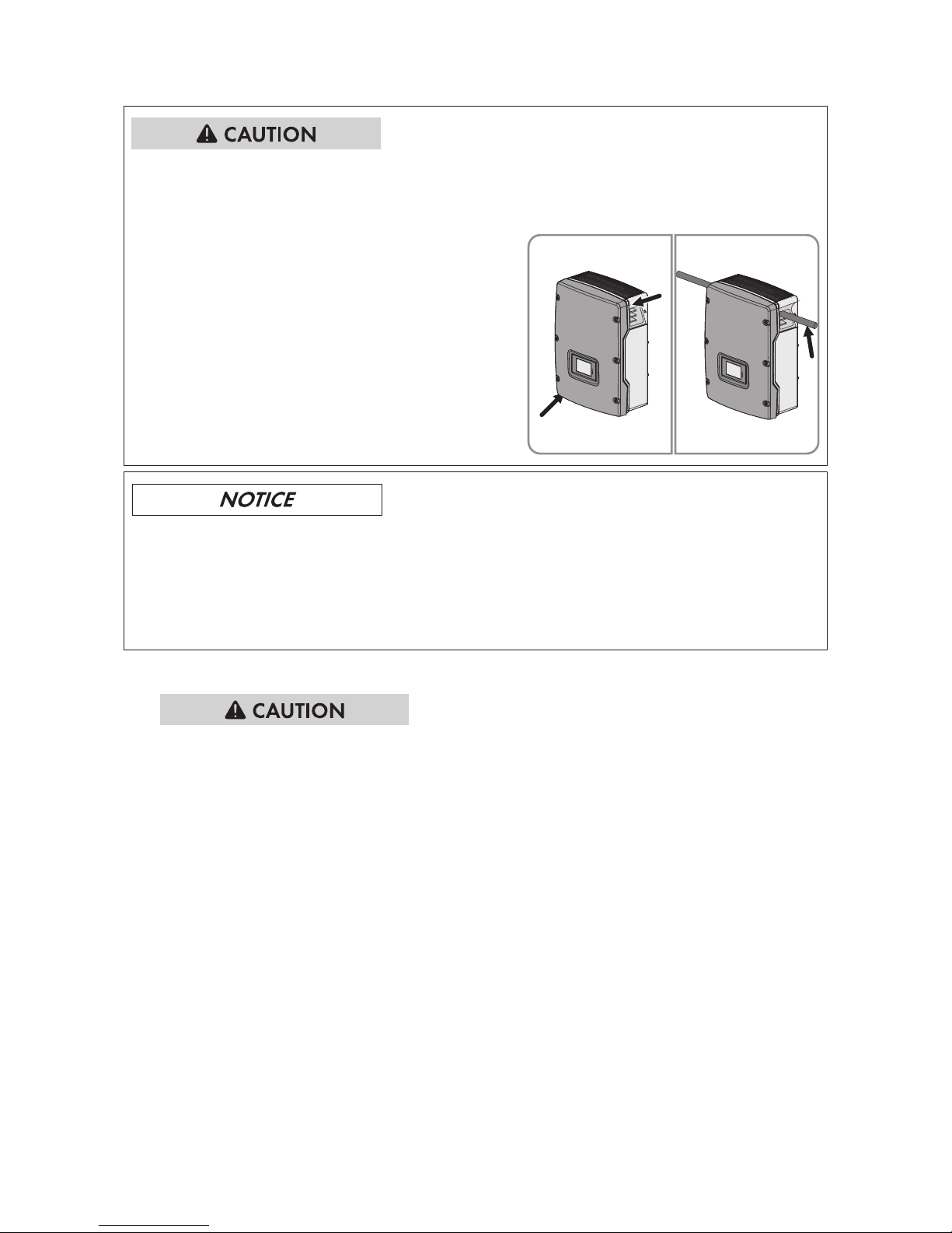
Risk of injury when lifting the inverter, or if it is dropped
The inverter weighs 38kg. There is risk of injury if the inverter is lifted incorrectly or dropped while
being transported or when attaching it to or removing it from the wall mounting bracket.
• Carry and lift the inverter upright with the help
of several people. Use both hands to grasp the
recessed grips at the top and bottom, or use a
steel rod (diameter: 30mm at maximum). This
will prevent the inverter from tipping forward.
Damage to the ESS pin connector from dirt and foreign bodies
In single-phase and three-phase inverters, the integrated differential current sensor detects the
current difference between the neutral conductor and the line conductor(s). This will impair the
function of the ESS.
• Always set the inverter down on a level support surface or lay it on its back.
Procedure:
1.
Risk of injury due to damaged cables
There may be power cables or other supply lines (e.g. gas or water) routed in the wall.
• Ensure that no lines are laid in the wall which could be damaged when drilling holes.
2. Align the wall mounting bracket horizontally on the wall and use it to mark the position of the
drill holes. Use at least one hole on the right-hand and left-hand side in the wall mounting
bracket.
3. Set the wall mounting bracket aside and drill the marked holes.
4. Insert screw anchors into the drill holes if the support surface requires them.
5. Secure the wall mounting bracket horizontally using screws and washers.
6. If the inverter is to be secured against theft, mark one drill hole or two drill holes for the
attachment of the security screw:
• Hook the inverter into the wall mounting bracket.
5Mounting
SMA Solar Technology AG
Operating ManualSTP5-12TL-20-BE-en-1524
Page 25
• Mark the drill hole on the left-hand or righthand side. If you want to secure the inverter
with two safety screws, mark one drill hole
on the left-hand side and one on the righthand side.
• Remove the inverter by lifting it vertically up and off the wall mounting bracket.
• Drill the hole or holes to attach the safety screw(s) and insert the screw anchor(s).
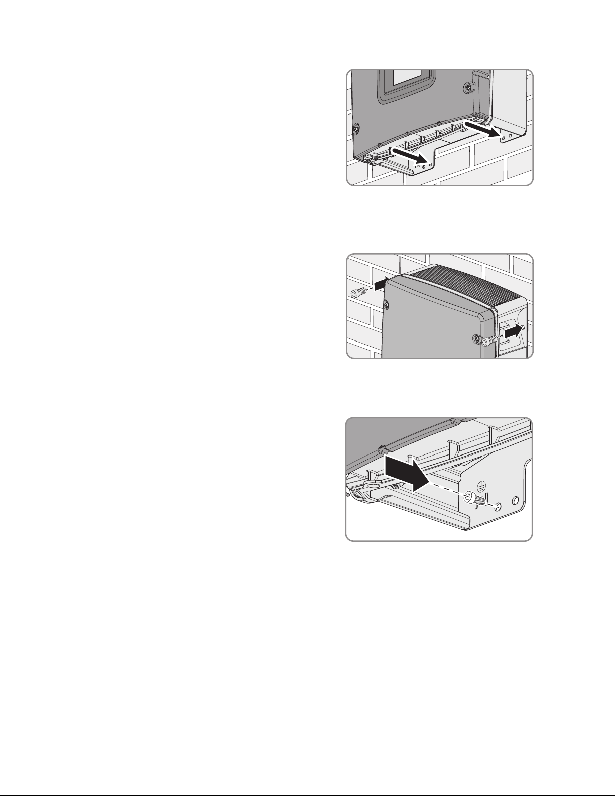
7. Hook the inverter into the wall mounting bracket.
8. Secure the inverter to the wall mounting bracket
on both sides using the M6x8 screws provided
and an Allen key (AF5). Only tighten the screws
hand-tight.
9. Close the recessed grips with the ventilation grids. Ensure that the assignment is correct. The
correct assignment is marked on the inside of each ventilation grid: links/left for the left-hand
side and rechts/right for the right-hand side.
10. Once the holes for attaching the safety screw
have been pre-drilled, secure the inverter with at
least one safety screw through the pre-drilled
hole.
11. Ensure that the inverter is securely in place.
5 Mounting
SMA Solar Technology AG
Operating Manual 25STP5-12TL-20-BE-en-15
Page 26
6 Electrical Connection
6.1 Safety during Electrical Connection
Danger to life due to high voltages of the PV array
When exposed to sunlight, the PV array generates dangerous DC voltage, which is present in the
DC conductors and the live components of the inverter. Touching the DC conductors or the live
components can lead to lethal electric shocks. If you disconnect the DC connectors from the
inverter under load, an electric arc may occur leading to electric shock and burns.
• Do not touch non-insulated cable ends.
• Do not touch the DC conductors.
• Do not touch any live components of the inverter.
• Have the inverter mounted, installed and commissioned only by qualified persons with the
appropriate skills.
• If an error occurs, have it rectified by qualified persons only.
• Prior to performing any work on the inverter, disconnect it from all voltage sources as
described in this document.
Damage to seals on the enclosure lids in subfreezing conditions
If you open the enclosure lid when temperatures are below freezing, the enclosure lid seal could
be damaged. This can lead to moisture entering the inverter.
• Only open the enclosure lid if the ambient temperature is not below -5°C
• If a layer of ice has formed on the seal of the lid when temperatures are below freezing,
remove it prior to opening the enclosure lid (e.g. by melting the ice with warm air). Observe
the applicable safety regulations.
Damage to the inverter due to electrostatic discharge
Touching electronic components can cause damage to or destroy the inverter through
electrostatic discharge.
• Ground yourself before touching any component.
6Electrical Connection
SMA Solar Technology AG
Operating ManualSTP5-12TL-20-BE-en-1526
Page 27

6.2 Overview of the Connection Area
6.2.1 View from Below
Figure 6: Connection areas and enclosure openings at the bottom of the inverter
Position Designation
A Positive DC connectors, input A
B Positive DC connectors, input B
C Pin connector for the ESS
D Pin connector with filler plug for the network connection
E Cable gland M25 with filler plug for the data cables
F Enclosure opening for the AC cable
G Negative DC connectors, input A
H Negative DC connectors, input B
6 Electrical Connection
SMA Solar Technology AG
Operating Manual 27STP5-12TL-20-BE-en-15
Page 28
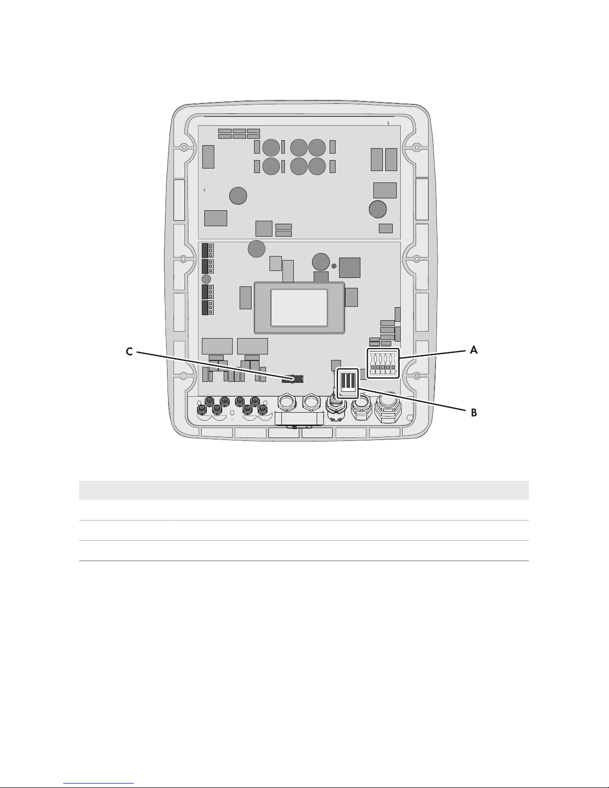
6.2.2 Interior View
Figure 7: Connection areas in the interior of the inverter
Position Designation
A Connecting terminal plate for the AC cable
B Multifunction relay with protective cover
C Slot for 485DataModuleTypeB or SMAPowerControlModule
6Electrical Connection
SMA Solar Technology AG
Operating ManualSTP5-12TL-20-BE-en-1528
Page 29
6.3 AC Connection
6.3.1 Requirements for the AC Connection
Cable requirements:
• External diameter: 12mm to 21mm
• Conductor cross-section: 1.5 to 6 mm²
• Insulation stripping length: 18mm
• The cable must be dimensioned in accordance with the local and national directives for the
dimensioning of cables. The requirements for the minimum wire size derive from these
directives. Examples of factors influencing cable dimensioning are: nominal AC current, type of
cable, routing method, cable bundling, ambient temperature and maximum desired line losses
(for calculation of line losses, see the design software "SunnyDesign" from software
version2.0 at www.SMA-Solar.com).
Load-break switch and cable protection:
Damage to the inverter due to the use of screw-type fuses as load-break switches
Screw-type fuses (e.g. DIAZED fuse or NEOZED fuse) are not load-break switches.
• Do not use screw-type fuses as load-break switches.
• Use a load-break switch or circuit breaker as a load disconnection unit (for information and
design examples, see the Technical Information "Circuit Breaker" at www.SMA-Solar.com).
☐ In PV systems with multiple inverters, protect each inverter with a separate three-phase circuit
breaker. Make sure to observe the maximum permissible fuse protection (see Section11
"Technical Data", page59). This will prevent residual voltage being present at the
corresponding cable after disconnection.
☐ Loads installed between the inverter and the circuit breaker must be fused separately.
Residual-current monitoring unit:
☐ If an external residual-current device is required, install a residual-current device which trips at
a residual current of 100mA or higher (for details on selecting a residual-current device, see
the Technical Information ""Criteria for Selecting a Residual-Current Device"" at www.SMASolar.com).
☐ If a residual-current device with a tripping threshold of 30mA is required and used, you must
set the tripping threshold of the residual-current device in the inverter to 30mA (see
Section8.7, page51).
6 Electrical Connection
SMA Solar Technology AG
Operating Manual 29STP5-12TL-20-BE-en-15
Page 30
Overvoltage category:
The inverter can be used in grids of overvoltage categoryIII or lower in accordance with
IEC60664-1. That means that the inverter can be permanently connected to the grid-connection
point of a building. In case of installations with long outdoor cabling routes, additional measures to
reduce overvoltage categoryIV to overvoltage categoryIII are required (see the Technical
Information "Overvoltage Protection" at www.SMA-Solar.com).
6.3.2 Connecting the Inverter to the Utility Grid
Requirements:
☐ The connection requirements of the grid operator must be met.
☐ The grid voltage must be in the permissible range. The exact operating range of the inverter is
specified in the operating parameters.
Procedure:
1. Disconnect the circuit breaker from all three line conductors and secure against reconnection.
2. Unscrew all six screws of the enclosure lid using an Allen key (AF5) and remove the enclosure
lid. Ensure that the conical spring washers are retained.
3. Remove the adhesive tape from the enclosure opening for the AC cable.
4. Attach the M32x1.5 cable gland to the enclosure opening for the AC cable using a counter
nut.
5. Route the AC cable into the inverter through the cable gland. If necessary, slightly loosen the
swivel nut of the cable gland.
6. Dismantle the AC cable.
7. Shorten L1, L2, L3 and N by 5mm each.
8. Strip 18mm of the insulation from each of L1, L2, L3, N and the grounding conductor.
9. Push the safety levers of the AC connecting terminal plate right up to the stop.
10.
Risk of fire if two conductors are connected to one terminal
If you connect two conductors to a terminal, a fire can occur due to a bad electrical
connection.
• Never connect more than one conductor per terminal.
11. Connect PE, N, L1, L2 and L3 to the connecting terminal plate for the AC cable according to
the labeling. The direction of the rotating magnetic field of L1, L2 and L3 is not relevant.
6Electrical Connection
SMA Solar Technology AG
Operating ManualSTP5-12TL-20-BE-en-1530
Page 31
12.
Danger of crushing fingers when locking levers snap shut
The locking levers close by snapping down fast and hard.
• Press the locking levers of the connecting terminal plate for the AC cable down with your
thumb only.
• Do not grip the entire connecting terminal plate for the AC cable.
• Do not place your fingers under the locking levers.
13. Make sure that all conductors are securely in place.
14. Tighten the swivel nut of the cable gland.
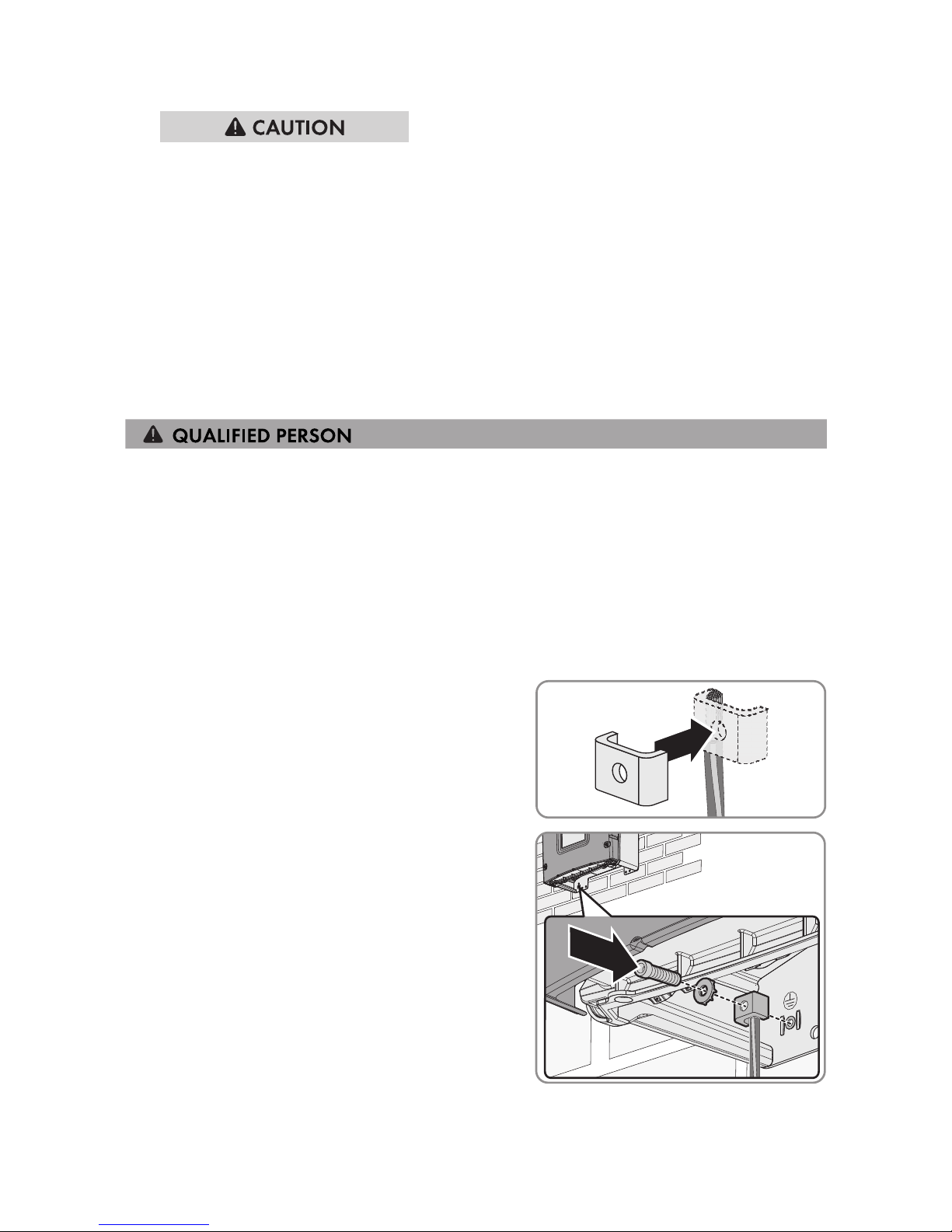
6.3.3 Connecting Additional Grounding
If additional grounding or equipotential bonding is required locally, you can connect additional
grounding to the inverter. This prevents touch current if the grounding conductor at the terminal for
the AC cable fails. The required clamping bracket, the screw and the conical spring washer are
part of the scope of delivery of the inverter.
Cable requirement:
☐ Grounding cable cross-section: 16mm² at maximum
Procedure:
1. Strip the grounding cable insulation.
2. Lead the clamping bracket over the grounding
cable. Arrange the grounding cable on the lefthand side.
3. Screw the clamping bracket tight using the
M6x16 cylindrical screw and the conical spring
washer M6 (torque: 6Nm). The teeth of the
conical spring washer must face the clamping
bracket.
6 Electrical Connection
SMA Solar Technology AG
Operating Manual 31STP5-12TL-20-BE-en-15
Page 32
6.4 Connecting the Multifunction Relay
6.4.1 Procedure for connecting the multifunction relay
Procedure See
1. Select for which operating mode you would like to use the
multifunction relay.
Section6.4.2, page32
2. Connect to the multifunction relay according to the operating mode and the associated connection variant.
Section6.4.3, page32
and Section6.4.4,
page37
3. After commissioning the inverter, change the operating
mode of the multifunction relay, if necessary.
User manual under
www.SMA-Solar.com
6.4.2 Operating Modes of the Multifunction Relay
Operating mode of multifunction relay (Mlt.OpMode)
Description
Fault indication (FltInd)
The multifunction relay controls a display device (e.g. a warning
light) which, depending on the type of connection, signals either an
error or the undisturbed operation of the inverter.
Self-consumption (SelfCsmp)
The multifunction relay switches loads on or off, depending on the
power production of the PV system.
Control via communication (ComCtl)
The multifunction relay switches loads on or off according to commands transmitted by a communication product.
Battery bank (BatCha)
The multifunction relay controls the charging of the batteries depending on the power production of the PV system.
Fan control (FanCtl)
The multifunction relay controls an external fan, depending on the
temperature of the inverter.
Switching status grid relay (GriSwCpy)
The local grid operator may require that a signal is transmitted as
soon as the inverter connects to the utility grid. The multifunction relay can be used to trigger this signal.
6.4.3 Connection Options
The connection procedures vary, depending on the operating mode.
Operating mode Connection option
Fault indication (FltInd)
Using the Multifunction Relay as a Fault Indicator Contact
Self-consumption (SelfCsmp)
Controlling loads via the multifunction relay or charging batteries depending on the power production of the PV system
6Electrical Connection
SMA Solar Technology AG
Operating ManualSTP5-12TL-20-BE-en-1532
Page 33

Operating mode Connection option
Control via communication (ComCtl)
Controlling loads via the multifunction relay or charging batteries depending on the power production of the PV system
Battery bank (BatCha)
Controlling loads via the multifunction relay or charging batteries depending on the power production of the PV system
Fan control (FanCtl)
Connecting the external fan (see fan documentation)
Switching status grid relay (GriSwCpy)
Reporting the switching status of the grid relay
6 Electrical Connection
SMA Solar Technology AG
Operating Manual 33STP5-12TL-20-BE-en-15
Page 34
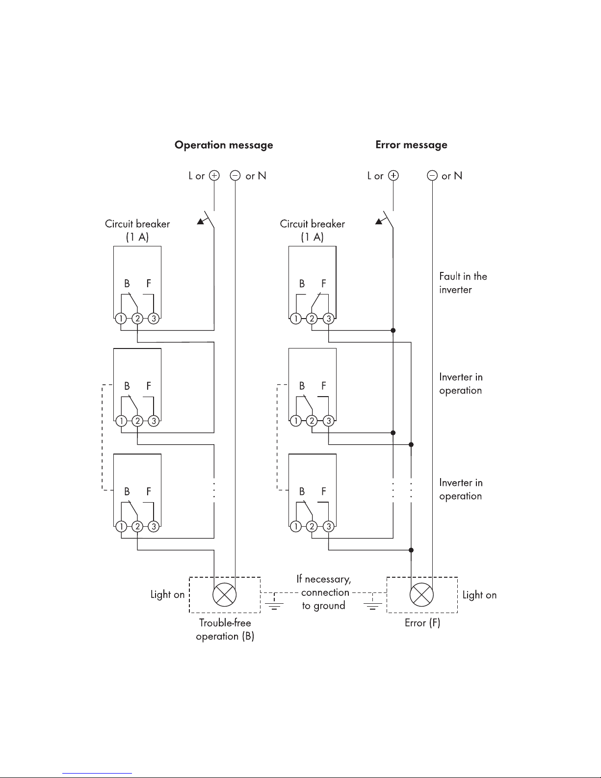
Using the Multifunction Relay as a Fault Indicator Contact
You can use the multifunction relay as a fault indicator contact and have an error or smooth
operation of the inverter displayed or signaled via a suitable display device. You can connect
multiple inverters to one fault indicator or operation indicator, as needed.
Figure 8: Circuit diagram with multiple inverters for connection to an operation indicator and circuit diagram for
connection to a fault indicator (example)
6Electrical Connection
SMA Solar Technology AG
Operating ManualSTP5-12TL-20-BE-en-1534
Page 35
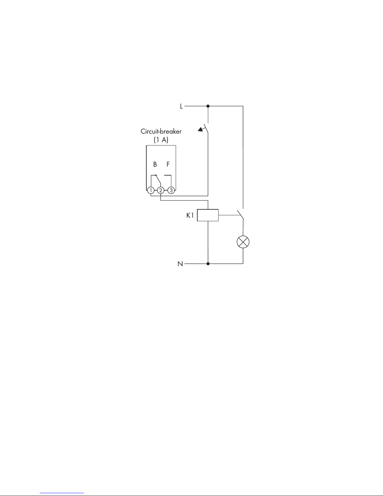
Controlling loads via the multifunction relay or charging batteries depending on
the power production of the PV system
The multifunction relay can control loads or charge batteries power-dependently. To enable this
function, you must connect a contactor (K1) to the multifunction relay. The contactor (K1) switches
the operating current for the load on or off. If you want batteries to be charged depending on the
available power, the contactor activates or deactivates the charging of the batteries.
Figure 9: Wiring diagram for connection for controlling a load or for the power-dependent charging of the
batteries
6 Electrical Connection
SMA Solar Technology AG
Operating Manual 35STP5-12TL-20-BE-en-15
Page 36
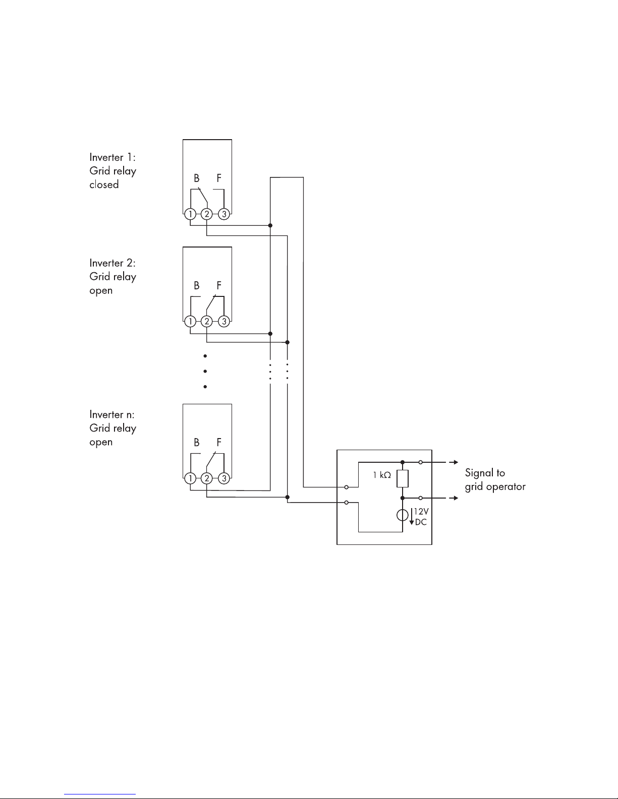
Reporting the switching status of the grid relay
The multifunction relay can trip a signal to the grid operator as soon as the inverter connects to the
utility grid. To enable this function, the multifunction relays of all inverters must be connected in
parallel.
Figure 10: Wiring diagram for signaling the switching status of the grid relay (example)
6Electrical Connection
SMA Solar Technology AG
Operating ManualSTP5-12TL-20-BE-en-1536
Page 37
6.4.4 Connection to the Multifunction Relay
Figure 11: Connecting terminal plate for the connection to the multifunction relay
Requirement:
☐ The technical requirements of the multifunction relay must be met (see Section11 "Technical
Data", page59).
Cable requirements:
☐ The cable must be double-insulated.
☐ External diameter: 5 mm to 12 mm
☐ Conductor cross-section: 0.08 mm² ... 2.5mm²
☐ The cable type and cable-laying method must be appropriate for the application and
location.
Destruction of the multifunction relay as a result of excessive contact load
• Observe the maximum switching voltage and maximum switching current (see Section11
"Technical Data", page59).
• When connecting the multifunction relay to the utility grid, fuse the multifunction relay with a
separate circuit breaker.
Operating the multifunction relay and 485DataModuleTypeB or
SMAPowerControlModule in parallel
If you want to operate the multifunction relay and the 485DataModuleTypeB or the
SMAPowerControlModule in parallel, a voltage of no more than 30VDC or 25VAC may
be connected to the multifunction relay.
6 Electrical Connection
SMA Solar Technology AG
Operating Manual 37STP5-12TL-20-BE-en-15
Page 38

Procedure:
1. When connecting to the utility grid, fuse the multifunction relay with a separate circuit breaker.
2.
Danger to life due to high voltages
• Ensure that the inverter is disconnected from all voltage sources (see Section10,
page57).
3. Prepare the cable:
• Dismantle the cable by no more than 15mm.
• Strip off the conductor insulation by max. 8mm.
4. Prepare the cable gland M25 for the connection to the multifunction relay as follows:
• Remove the swivel nut from the cable gland and remove the filler plug.
• Remove the one-hole cable support sleeve from the cable gland and insert the cable into
the one-hole cable support sleeve.
• Press the one-hole cable support sleeve with the cable into the cable gland and lead the
cable into the inverter.
• Screw the swivel nut onto the cable gland.
5. Remove the protective cover of the multifunction relay.
6. Depending on the operating mode, connect the cable to the connecting terminal plate for the
connection to the multifunction relay in accordance with the circuit diagram (see Section6.4.3,
page32).
7.
Danger to life due to live cables
If, during inverter operation, an insulated conductor (L1, L2 or L3) becomes detached from the
AC terminal, there is a risk of the multifunction relay cables being live. Touching the cables can
cause fatal electric shock.
• Reattach the protective cover to the multifunction relay. This isolates the AC connection
area in the inverter from other terminals.
8. Tighten the swivel nut of the cable gland.
6.5 DC Connection
6.5.1 Requirements for the DC Connection
Requirements for the PV modules per input:
☐ All PV modules must be of the same type.
☐ All PV modules must be aligned and tilted identically.
☐ On the coldest day based on statistical records, the open-circuit voltage of the PV array must
never exceed the maximum input voltage of the inverter.
6Electrical Connection
SMA Solar Technology AG
Operating ManualSTP5-12TL-20-BE-en-1538
Page 39
☐ The same number of series-connected PV modules must be connected to each string.
☐ The maximum input current per string must be maintained and must not exceed the through-
fault current of the DC connectors (see Section11 "Technical Data", page59).
☐ The thresholds for the input voltage and the input current of the inverter must be adhered to
(see Section11 "Technical Data", page59).
☐ The positive connection cables of the PV modules must be fitted with the positive DC
connectors (for information on assembling DC connectors, see the DC connector installation
manual).
☐ The negative connection cables of the PV modules must be fitted with the negative DC
connectors (for information on assembling DC connectors, see the DC connector installation
manual).
Use of Y adapters for parallel connection of strings
The Y adapters must not be used to interrupt the DC circuit.
• Do not use the Y adapters in the immediate vicinity of the inverter. The adapters must not
be visible or freely accessible.
• In order to interrupt the DC circuit, always disconnect the inverter as described in this
document (see Section10, page57).
6.5.2 Connecting the PV Array
Destruction of the inverter due to overvoltage
If the open-circuit voltage of the PV modules exceeds the maximum input voltage of the inverter,
the inverter can be destroyed due to overvoltage.
• If the open-circuit voltage of the PV modules exceeds the maximum input voltage of the
inverter, do not connect any strings to the inverter and check the design of the PV system.
Destruction of the measuring device due to overvoltage
• Only use measuring devices with a DC input voltage range of 1000V or higher.
Procedure:
1. Ensure that the circuit breaker is switched off from all three line conductors and that it cannot
be reconnected.
2. If the ESS is plugged in, remove the ESS.
3. If the protective cover is mounted, loosen the two screws of the protective cover using an Allen
key (AF5) and remove the protective cover.
6 Electrical Connection
SMA Solar Technology AG
Operating Manual 39STP5-12TL-20-BE-en-15
Page 40

4. Ensure that there is no ground fault in the PV array (see service manual at www.SMASolar.com).
5. Check whether the DC connectors have the correct polarity.
If the DC connector is equipped with a DC cable of the wrong polarity, the DC connector must
be assembled again. The DC cable must always have the same polarity as the DC connector.
6. Ensure that the open-circuit voltage of the PV array does not exceed the maximum input
voltage.
7. Connect the assembled DC connectors to the inverter.
☑ The DC connectors snap into place.
6Electrical Connection
SMA Solar Technology AG
Operating ManualSTP5-12TL-20-BE-en-1540
Page 41

8.
Damage to the inverter due to moisture ingress
The inverter is only properly sealed when all unused DC inputs are closed with DC connectors
and sealing plugs.
• Do not insert the sealing plugs directly into the DC inputs on the inverter.
• For unused DC connectors, push down the
clamping bracket and push the swivel nut
up to the thread.
• Insert the sealing plug into the DC
connector.
• Tighten the DC connector (torque: 2Nm).
• Insert the DC connectors with sealing plugs
into the corresponding DC inputs on the
inverter.
☑ The DC connectors snap into place.
9. Ensure that all DC connectors are securely in place.
6 Electrical Connection
SMA Solar Technology AG
Operating Manual 41STP5-12TL-20-BE-en-15
Page 42
7 Commissioning
7.1 Commissioning Procedure
Before you can commission the inverter, you must check various settings and make changes if
necessary. This section describes the procedure and gives an overview of the steps, which must
always be performed in the prescribed sequence.
Procedure See
1. Check which country data set the inverter is set to. Supplementary sheet with
the default settings, type label or display
2. If the country data set is not set correctly for your country
or your purpose, adjust to the required country data set
and the corresponding display language within the first
ten feed-in hours via the rotary switches in the inverter.
Section7.2, page42
3. When using BLUETOOTH communication: if the inverter is
to communicate with several BLUETOOTH devices, or if
BLUETOOTH is not to be used for communication, set the
NetID.
Section7.3, page43
4. Commission the inverter. Section7.4, page45
7.2 Configuring the Country Data Set
Set the country data set appropriate for your country or purpose within the first tenfeed-in hours via
the rotary switches in the inverter. After the first ten feed-in hours, the country data set can only be
changed by means of a communication product.
A display language is assigned to every country data set. If the display language of the country
data set does not match the required language, you can change it after commissioning (see
Section8.2 "Changing the Display Language", page47).
Procedure:
1. Determine the rotary switch position for your country and purpose. Call up the Technical
Information "Overview of the Rotary Switch Settings" at www.SMA-Solar.com.
2.
Danger to life due to high voltages
• Ensure that the inverter is disconnected from all voltage sources and that the enclosure lid
is removed (see Section10, page57).
7Commissioning
SMA Solar Technology AG
Operating ManualSTP5-12TL-20-BE-en-1542
Page 43
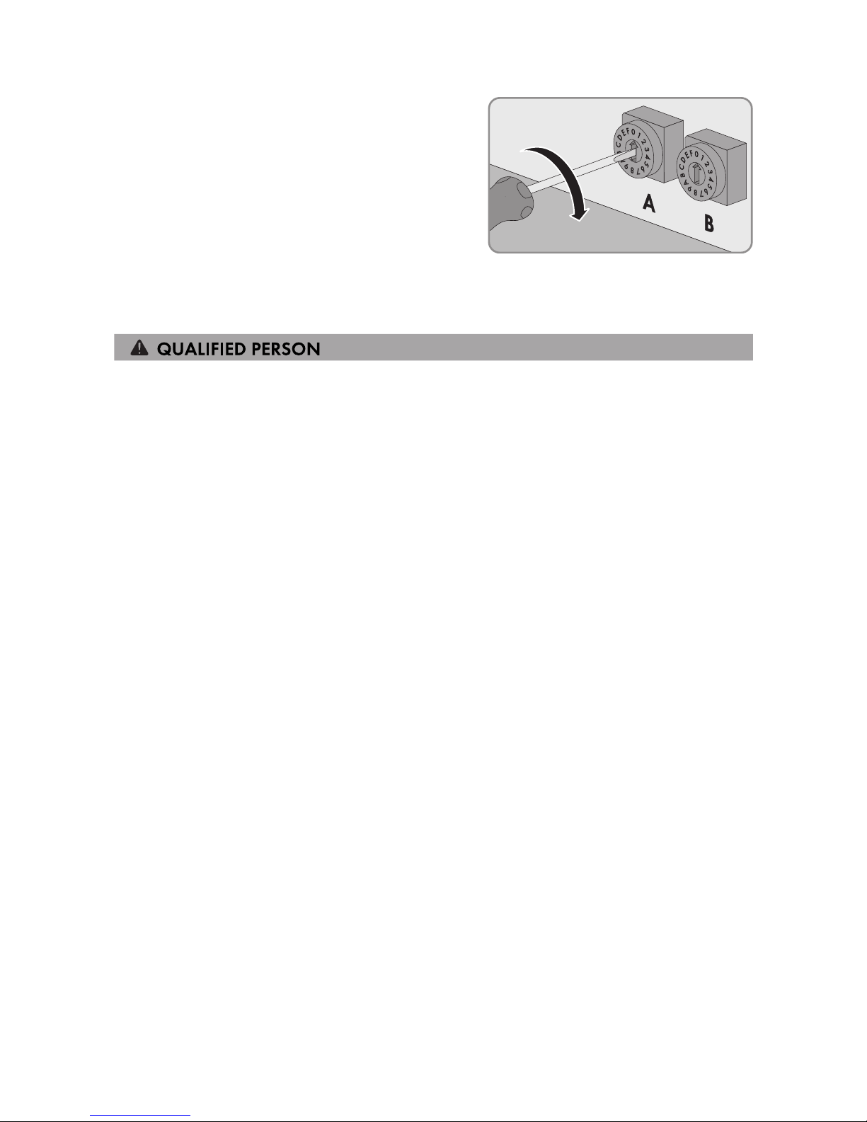
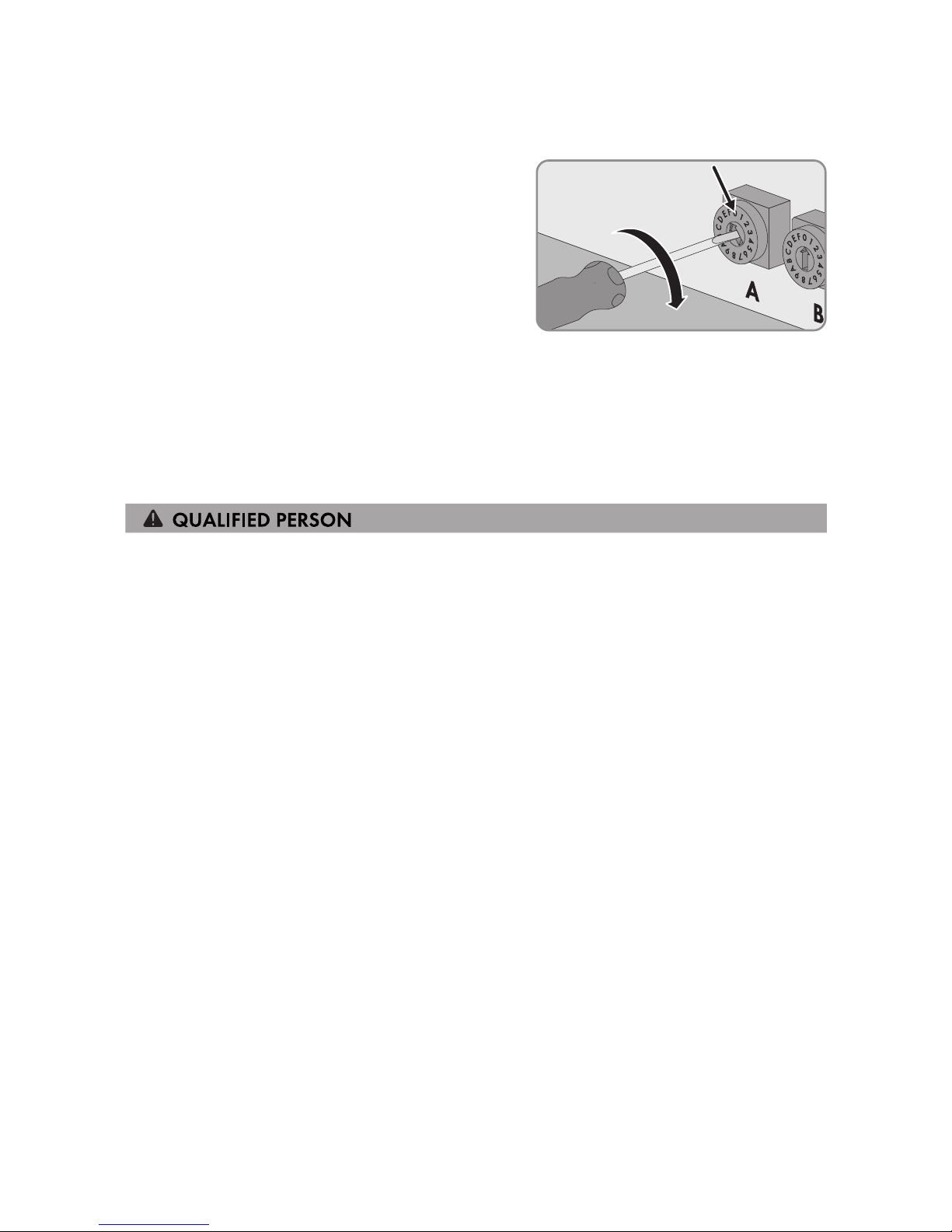
3. Set the rotary switches A and B to the required
position using a flat-blade screwdriver (blade
width: 2.5mm).
☑ The inverter will adopt the setting after commissioning. This can take up to five minutes.
7.3 Setting the NetID
If the inverter is equipped with BLUETOOTH, you can set the NetID of the inverter. By default, the
NetID is set to 1 for all SMAinverters and SMAcommunication products with BLUETOOTH. If your
PV system consists of an inverter and a maximum of one further BLUETOOTH device (e.g. computer
with BLUETOOTH interface or SMAcommunication product), you can leave the NetID set to 1.
You must change the NetID in the following cases:
• If your PV system consists of one inverter and two other BLUETOOTH devices (e.g. computer
with BLUETOOTH interface and SMA communication product) or of multiple inverters with
BLUETOOTH, you must change the NetID of your PV system. This enables you to communicate
using multiple BLUETOOTH devices.
• If another PV system with BLUETOOTH is located within 500m of your PV system, you must
change the NetID of your PV system. This will help keep both PV systems separate.
• If you do not wish to communicate via BLUETOOTH, deactivate the BLUETOOTH
communication on your inverter. This will protect your PV system from unauthorized access.
7 Commissioning
SMA Solar Technology AG
Operating Manual 43STP5-12TL-20-BE-en-15
Page 44
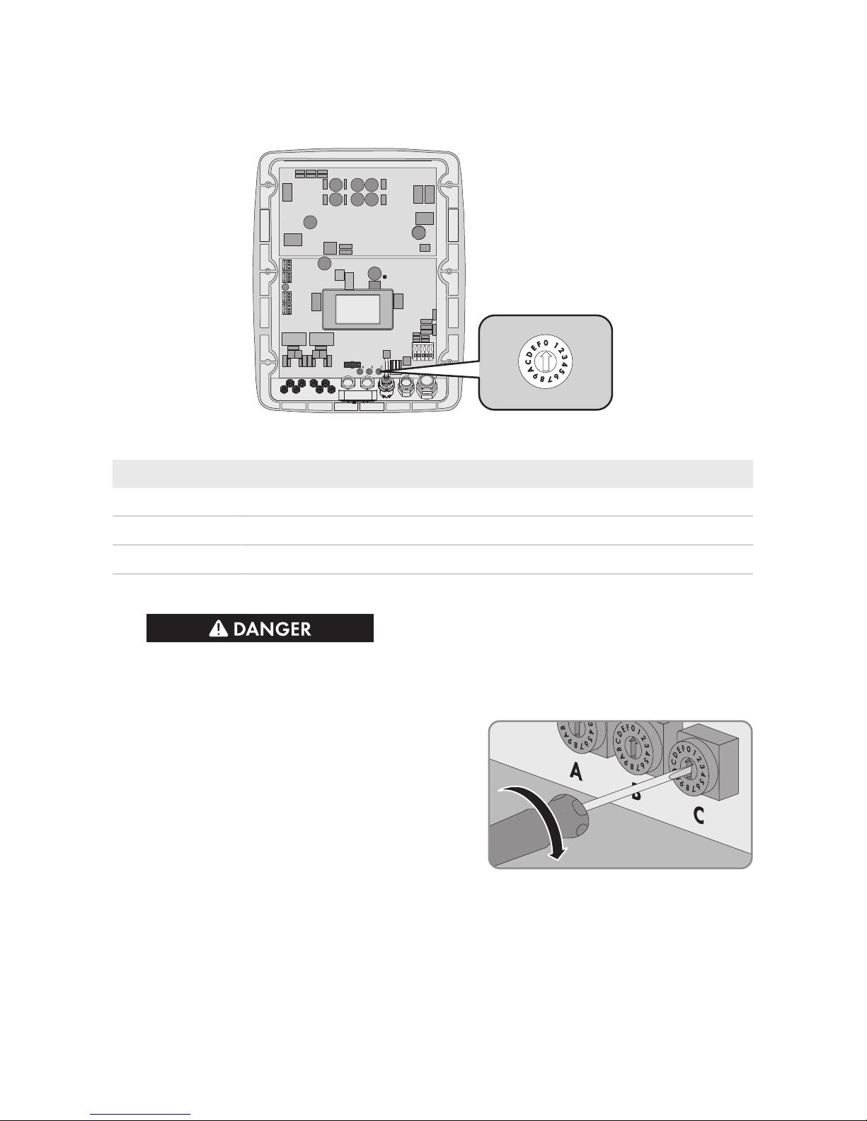
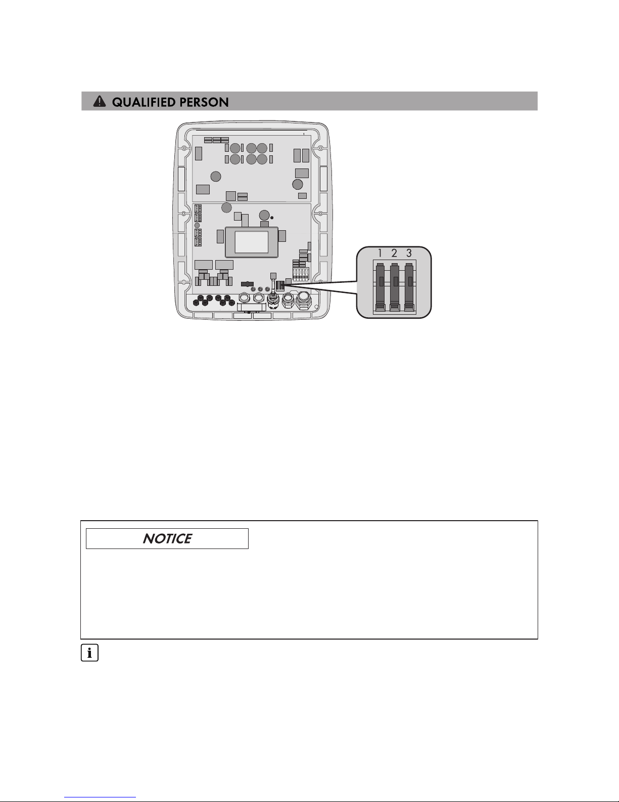
All BLUETOOTH devices in a PV system must have the same NetID. You can set a new NetID in the
inverter by means of the rotary switch C.
Figure 12: Positions of rotary switch C
Position Explanation
0 Communication via BLUETOOTH is deactivated.
1 Communication via BLUETOOTH with a further BLUETOOTH device
2 to F NetID for communication via BLUETOOTH with multiple BLUETOOTH devices
Procedure:
1.
Danger to life due to high voltages
• Ensure that the inverter is disconnected from all voltage sources (see Section10,
page57).
2. To set a new NetID, set the rotary switch C to the
determined NetID using a flat-blade screwdriver
(blade width: 2.5mm).
7Commissioning
SMA Solar Technology AG
Operating ManualSTP5-12TL-20-BE-en-1544
Page 45
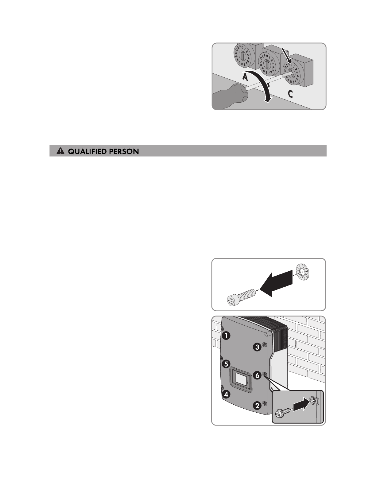
3. To deactivate communication via BLUETOOTH,
set the rotary switch C to position 0 using a flatblade screwdriver (blade width: 2.5mm). This
will protect your PV system from unauthorized
access.
☑ The inverter will adopt the setting after commissioning. This can take up to five minutes.
7.4 Commissioning the Inverter
Requirements:
☐ The inverter must be correctly mounted.
☐ The circuit breaker must be correctly rated.
☐ All cables must be correctly connected.
☐ Unused DC inputs must be sealed using the corresponding DC connectors and sealing plugs.
☐ The country data set must be set correctly for the country or the purpose.
Procedure:
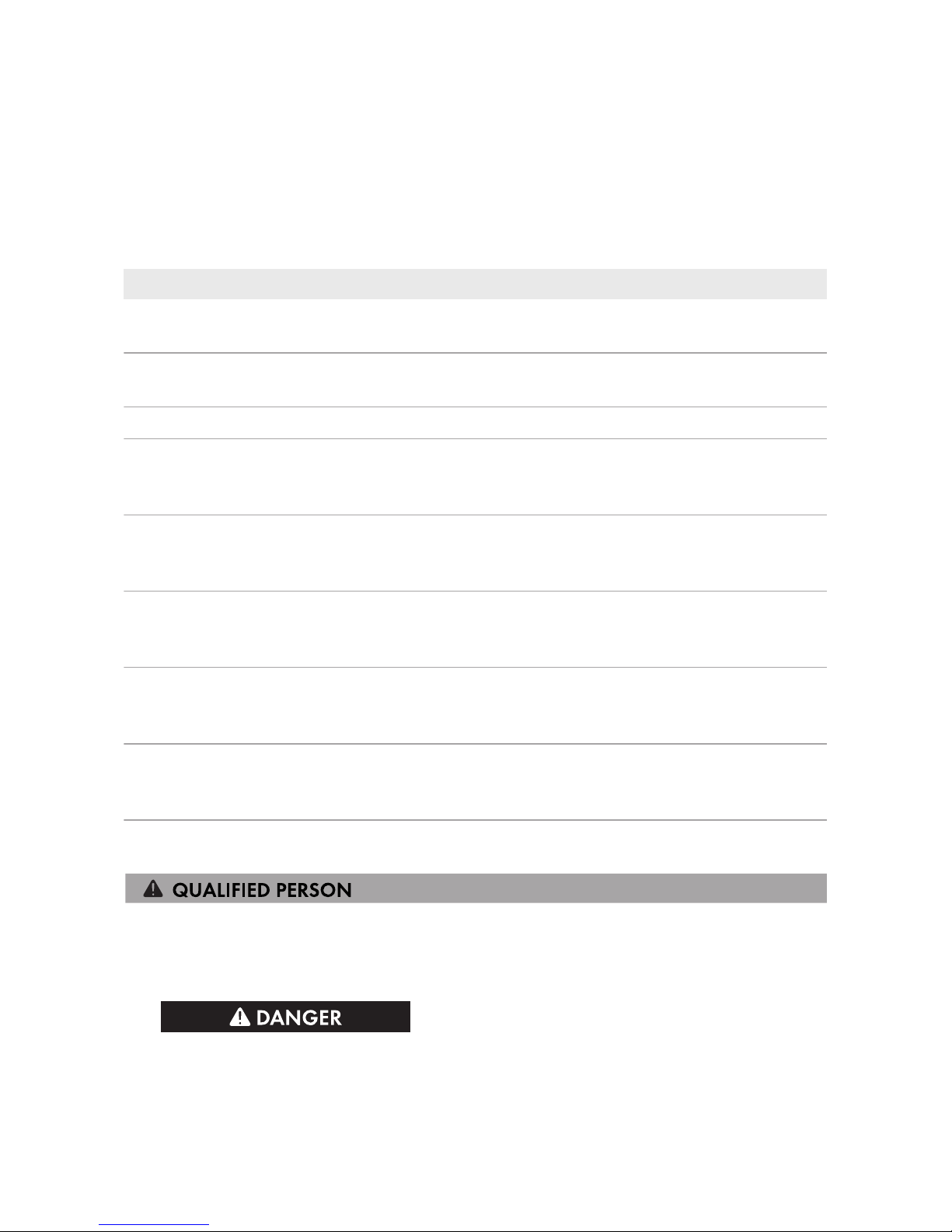
1. Mount the enclosure lid:
• Fit one conical spring washer to each
screw. The grooved side of the conical
spring washer must face the screw head.
• Position the enclosure lid with the six screws
on the enclosure and tighten all screws in
the sequence 1 to 6 using an Allen key
(AF5) (torque: 6Nm ± 0.5Nm).
☑ The teeth of the conical spring washer
press into the enclosure lid. This ensures
that the enclosure lid is grounded.
2. Secure the protective cover using two screws and an Allen key (AF5).
3. Securely plug in the ESS.
7 Commissioning
SMA Solar Technology AG
Operating Manual 45STP5-12TL-20-BE-en-15
Page 46

4. Switch on the circuit breaker of all three line conductors.
5. If the multifunction relay is used, switch on any supply voltage to the load.
☑ All three LEDs start to glow and the start-up phase begins. The start-up phase may take
several minutes.
☑ The green LED is glowing and the display alternates between the firmware version, the serial
number or designation of the inverter, the NetID, the IP address, the subnet mask, the
configured country data set and the display language.
✖ The green LED is flashing?
Possible cause of error: the DC input voltage is still too low or the inverter is monitoring the
utility grid.
• Once the DC input voltage is sufficiently high and the grid-connection conditions are met,
the inverter will start operation.
✖ The red LED is glowing and an error message and event number appear in the display?
• Rectify the error (see the service manual at www.SMA-Solar.com).
7Commissioning
SMA Solar Technology AG
Operating ManualSTP5-12TL-20-BE-en-1546
Page 47
8 Configuration
8.1 Configuration Procedure
Once you have commissioned the inverter, you may have to adjust various settings via the rotary
switches in the inverter or via a communication product. This section describes the procedure for
configuration and gives an overview of the steps you must perform in the prescribed order.
Procedure See
1. If the display language is not set correctly, adjust the settings.
Section8.2, page47
2. If you want to integrate the inverter into a Speedwire network, connect the inverter to the network.
Section8.3, page48
3. Integrate the inverter into the network. Section8.4, page49
4. To manage the PV system data or to set the inverter parameters, capture the inverter in a communication product.
Manual of the communication product at www.SMASolar.com
5. Change the system time and system password. Manual of the communica-
tion product at www.SMASolar.com
6. If a residual-current device with a tripping threshold of
30mA was specified and has been installed, set the tripping threshold of the residual-current device.
Section8.7, page51
7. If using the multifunction relay, ensure that the operating
mode is set correctly and adjust any further settings for the
operating mode as necessary.
Section8.8, page51
8. For partially shaded PV modules and depending on the
given shading situation, you should set the interval at
which the inverter optimizes the MPP of the PV system.
Section8.9, page52
8.2 Changing the Display Language
If the language for the country data set is not the language you want to use, you can change the
display language as follows:
Procedure:
1.
Danger to life due to high voltages
• Disconnect the inverter from all voltage sources and open the enclosure lid (see
Section10, page57).
8 Configuration
SMA Solar Technology AG
Operating Manual 47STP5-12TL-20-BE-en-15
Page 48
2. Determine the rotary switch setting for the desired display language. Call up the Technical
Information "Overview of the Rotary Switch Settings" at www.SMA-Solar.com.
3. Set the rotary switch A to 0 using a flat-blade
screwdriver (blade width: 2.5mm). This ensures
that the selected data country set remains
unchanged.
4. Set the rotary switch B to the required language using a flat-blade screwdriver (blade width:
2.5mm).
5. Recommission the inverter (see service manual at www.SMA-Solar.com).
☑ The inverter adopts the settings after commissioning. This can take up to five minutes.
8.3 Connecting the Inverter to the Network
Additionally required material (not included in the scope of delivery):
☐ One mating plug for RJ45 pin connector in accordance with IEC61076-3-106, model 4 with
push-pull lock
SMA Solar Technology AG recommends the plug sets "STXV4RJ45" from "Telegärtner" or
"IE-PS-V04P-RJ45-FH" from "Weidmüller".
☐ 1 network cable
Cable requirements:
The cable length and quality affect the quality of the signal. Observe the following cable
requirements.
☐ Cable type: 100BaseTx
☐ Cable category: Cat5, Cat5e, Cat6, Cat6a or Cat7
☐ Plug type: RJ45 of Cat5, Cat5e, Cat6 or Cat6a
☐ Shielding: SF/UTP, S/UTP, SF/FTP or S/FTP
☐ Number of insulated conductor pairs and insulated conductor cross-section: at least
2x2x0.22mm²
☐ Maximum cable length between two nodes when using patch cables: 50m
☐ Maximum cable length between two nodes with installation cable: 100m
☐ UV-resistant for outdoor use
8Configuration
SMA Solar Technology AG
Operating ManualSTP5-12TL-20-BE-en-1548
Page 49
Procedure:
1. Connect one end of the network cable to the mating plug (see mating plug documentation).
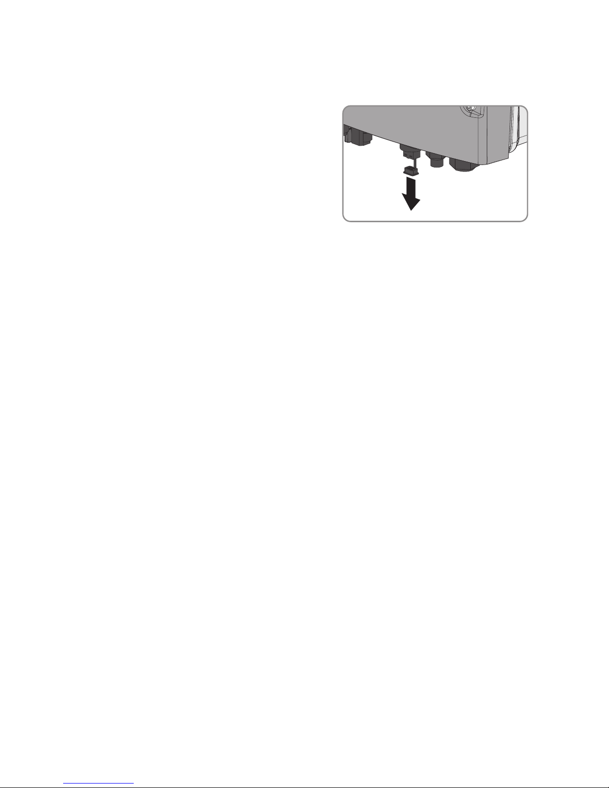
2. Remove the filler plug from the pin connector for
network connection to the inverter.
3. Connect the end of the network cable with the mating plug to the inverter. Insert the mating
plug firmly into the pin connector on the inverter.
4. Connect the other end of the network cable directly to the computer or router or connect it to
another node. You can only connect the inverter to other nodes via star topology.
8.4 Integrating the Inverter into the Network
If the router supports DHCP and DHCP is enabled, the inverter will automatically be integrated into
the network. You will not need to carry out network configuration.
If the router does not support DHCP, automatic network configuration will not be possible and you
will need to use the SMA Connection Assist to integrate the inverter into the network.
Requirements:
☐ The inverter must be in operation.
☐ There must be a router with Internet connection in the local network of the system.
☐ The inverter must be connected to the router.
Procedure:
• Integrate the inverter into the network by means of the SMAConnectionAssist. Download the
SMA Connection Assist and install it on the computer (see www.SMA-Solar.com).
8.5 Changing Operating Parameters
This section describes the basic procedure for changing operating parameters. Always change
operating parameters as described in this section. Some parameters that have sensitive functions
can only be viewed and changed by qualified persons (for further information on changing
parameters, refer to the manual of the communication product).
The operating parameters of the inverter are set to certain values by default. To optimize inverter
operation, you can change the operating parameters using a communication product.
Requirements:
☐ Depending on the type of communication, a computer with BLUETOOTH or Ethernet interface
must be available.
☐ A communication product corresponding to the type of communication used must be
available.
8 Configuration
SMA Solar Technology AG
Operating Manual 49STP5-12TL-20-BE-en-15
Page 50
☐ The inverter must be registered in the communication product.
☐ The changes to the grid-relevant parameters must be approved by the responsible grid
operator.
☐ When changing grid-relevant parameters, the SMAGridGuardcode must be available (see
"Application for SMAGridGuard Code" at www.SMA-Solar.com).
Procedure:
1. Call up the user interface of the communication product or software and log in as Installer or
User.
2. If required, enter the SMAGridGuardcode.
3. Select and set the required parameter.
4. Save settings.
8.6 Configuring the ModbusFunction
The Modbus interface is deactivated by default and the communication ports 502 set. In order to
access SMA invertes with SMA Modbus® or SunSpec® Modbus®, the Modbus interface must be
activated. After activating the interface, the communication ports of both IP protocols can be
changed.
For information on commissioning and configuration of the Modbus interface, see the Technical
Information "SMAModbus® Interface" or in the Technical Information "SunSpec® Modbus®
Interface" at www.SMA-Solar.com.
Data security during activated Modbus interface
If you activate the Modbus interface, there is a risk that unauthorized users may access and
manipulate the data or devices in your PV system.
• Take appropriate protective measures such as:
– Set up a firewall.
– Close unnecessary network ports.
– Only enable remote access via VPN tunnel.
– Do not set up port forwarding at the communication port in use.
– In order to deactivate the Modbus interface, reset the inverter to default settings or
deactivate the activated parameter again.
Procedure:
• Activate the Modbus interface and adjust the communication ports if necessary (see the
Technical Information "SMAModbus® Interface" or "SunSpec® Modbus® Interface" at
www.SMA-Solar.com).
8Configuration
SMA Solar Technology AG
Operating ManualSTP5-12TL-20-BE-en-1550
Page 51

8.7 Setting the Tripping Threshold of the Residual-Current
Device
If a residual-current device with a tripping threshold of 30mA is specified and installed, you must
set the parameter RCD adjustment to 30mA (for further information, see the Technical
Information ""Leading Leakage Currents"" at www.SMA-Solar.com).
The basic procedure for changing operating parameters is explained in another section (see
Section8.5 "Changing Operating Parameters", page49).
• Select the parameter RCDadjustment and set it to 30mA.
8.8 Changing the Operating Mode of the Multifunction
Relay
The default operating mode of the multifunction relay is Fault indication (FltInd) . If you decide to
use another operating mode and have established the correct electrical connection for this
operating mode and the associated connection variant, you will have to change the operating
mode of the multifunction relay and make other settings, if necessary.
The basic procedure for changing operating parameters is explained in another section (see
Section8.5 "Changing Operating Parameters", page49).
Procedure:
1. Select the parameter Operating mode of multifunction relay or Mlt.OpMode and set the
desired operating mode.
2. Once you have set the operating mode Self-consumption or SelfCsmp, you can configure
other settings:
• Select the parameter Minimum On power for MFR self-consumption or
Mlt.MinOnPwr and set the desired value. This will configure the power threshold from
which a load is to be activated.
• Select the parameter Minimum power On time, MFR self-consumption or
Mlt.MinOnPwrTmm and set the desired value. This will configure the minimum time for
which the power must have exceeded the minimum switch-on power threshold in order to
trip activation of the load.
• Select the parameter Minimum On time for MFR self-consumption or
Mlt.MinOnTmm and set the desired value. This will configure the minimum time for
which the load remains activated.
3. If you have set the operating mode Control via communication or ComCtl, select the
parameter Status of MFR with control via communication or Mlt.ComCtl.Sw and set the
desired value. This will configure the status at which the multifunction relay is controlled via a
communication product.
4. If you have set the operating mode Battery bank or BatCha, make further settings:
8 Configuration
SMA Solar Technology AG
Operating Manual 51STP5-12TL-20-BE-en-15
Page 52
• Select the parameter Minimum On power for MFR battery bank or
Mlt.BatCha.Pwr and set the desired value. This will configure the power threshold from
which the battery is to be charged.
• Select the parameter Minimum time before reconnection of MFR battery bank or
Mlt.BatCha.Tmm and set the desired value. This will configure the minimum time which
must elapse after charging the battery before the battery can be charged again.
8.9 Setting SMA OptiTrac Global Peak
For partially shaded PV modules, you should set the interval at which the inverter is to optimize the
MPP of the PV system. If you do not want to use SMAOptiTracGlobalPeak feature, you can
deactivate the feature.
The basic procedure for changing operating parameters is explained in another section (see
Section8.5 "Changing Operating Parameters", page49).
Procedure:
• Select the parameter Cycle time of the OptiTrac Global Peak algorithm or
MPPShdw.CycTms and set the required time interval. The ideal time interval is usually six
minutes. This value should only be increased if the shading situation changes extremely slowly.
☑ The inverter optimizes the MPP of the PV system at the predetermined time interval.
• In order to deactivate the SMAOptiTracGlobalPeak feature, select the parameter OptiTrac
Global Peak switched on or set MPPShdw.IsOn to Off.
8Configuration
SMA Solar Technology AG
Operating ManualSTP5-12TL-20-BE-en-1552
Page 53

9 Operation
9.1 LED Signals
The LEDs indicate the operating state of the inverter.
LED Status Explanation
Green LED glowing Feed-in operation
If an event occurs during feed-in operation, an event message will be shown on the display (for event messages see
the service manual at www.SMA-Solar.com).
flashing The conditions for feed-in operation are not yet met. As
soon as the conditions are met, the inverter will start feedin operation.
Red LED glowing Error
If an error occurs, the error message and the corresponding event number will be shown in the display. The error
must be rectified by a qualified person (for troubleshooting, see the service manual at www.SMA-Solar.com).
Blue LED glowing For inverters including BLUETOOTH as standard equip-
ment: BLUETOOTH communication is activated.
9.2 Display Overview
The display shows the current operating data of the inverter (e.g. current power, daily energy, total
energy) as well as events or errors. Power and energy are displayed as bars in a diagram.
9 Operation
SMA Solar Technology AG
Operating Manual 53STP5-12TL-20-BE-en-15
Page 54

Figure 13: Layout of the display (example)
Position Symbol Explanation
A - Current power
B - Energy on the current day
C - Total amount of energy fed in
D In inverters with BLUETOOTH: active BLUETOOTH connection
In inverters with BLUETOOTH: strength of BLUETOOTH signal
Active connection to a Speedwire network
Active connection to SunnyPortal
Multifunction relay is active
Power limitation due to excessive temperature
Active power limitation via PV system control
E - Line conductor to which the displayed values apply
9Operation
SMA Solar Technology AG
Operating ManualSTP5-12TL-20-BE-en-1554
Page 55

Position Symbol Explanation
F Utility grid
G - Event number of an error on the utility grid side
H - Output voltage or output current of a line conductor
I - Event number of an error in the inverter
K Grid relay
When the grid relay is closed, the inverter feeds into the utility
grid.
When the grid relay is open, the inverter is disconnected from
the utility grid.
L Inverter
M - Input voltage or input current of a line conductor
N - Event number of an error on the PV array side
O - Text line to display event and error messages
P PV array
Q - Diagram with the power curve of the last 16feed-in hours or
energy yields of the last 16days
• In order to switch between diagrams, tap once on the
enclosure lid.
R You can operate the display by tapping on the enclosure lid
(see Section9.3, page55).
The displayed error must be rectified on-site by a qualified person (for troubleshooting, see service manual at www.SMA-Solar.com).
The displayed error cannot be rectified on-site.
• Contact the Service (see Section13, page70).
9.3 Activating and Operating the Display
You can activate and operate the display by tapping on the enclosure lid.
Procedure:
1. Activate the display. Tap on the enclosure lid once.
☑ The backlight is switched on.
9 Operation
SMA Solar Technology AG
Operating Manual 55STP5-12TL-20-BE-en-15
Page 56

2. To move to the next line, tap on the enclosure lid once.
3. In order to switch between the power curve of the last 16feed-in hours and the energy yields
of the last 16days in the diagram, tap on the enclosure lid once.
9.4 Calling Up Display Messages of the Start-Up Phase
Various inverter information is displayed during the start-up phase that can be called up whenever
required during operation.
Procedure:
• Tap on the enclosure lid twice.
☑ The display shows all messages of the start-up phase in sequence.
9Operation
SMA Solar Technology AG
Operating ManualSTP5-12TL-20-BE-en-1556
Page 57
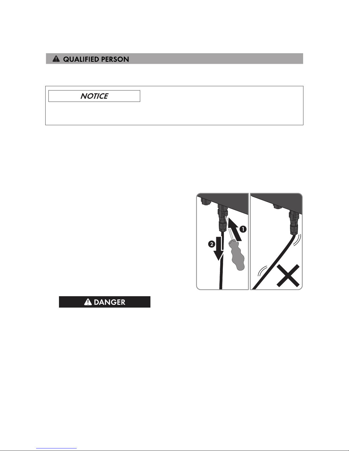
10 Disconnecting the Inverter from Voltage Sources
Prior to performing any work on the inverter, always disconnect it from all voltage sources as
described in this section. Always adhere to the prescribed sequence.
Destruction of the measuring device due to overvoltage
• Only use measuring devices with a DC input voltage range of 1000V or higher.
Procedure:
1. Disconnect the circuit breaker from all three line conductors and secure against reconnection.
2. Remove the ESS.
3. Loosen two screws of the protective cover using an Allen key (AF5) and remove the protective
cover.
4. Use a current clamp to ensure that no current is present in the DC cables.
5. Release and remove all DC connectors. To do
this, insert a flat-blade screwdriver or an angled
screwdriver (blade width: 3.5mm) into one of
the side slots and pull the DC connectors straight
out. Do not pull on the cable.
6.
Danger to life due to high voltages
The capacitors in the inverter take five minutes to discharge.
• Wait five minutes before opening the enclosure lid.
7. Ensure that no voltage is present at the DC inputs of the inverter.
8. Unscrew all the screws of the enclosure lid using an Allen key (AF5) and remove the
enclosure lid.
9. Use an appropriate measuring device to ensure that no voltage is present at the AC
connecting terminal plate between L1 and N, L2 and N, and L3 and N. Insert the test probe
into each round opening of the terminal.
10 Disconnecting the Inverter from Voltage Sources
SMA Solar Technology AG
Operating Manual 57STP5-12TL-20-BE-en-15
Page 58

10. Use an appropriate measuring device to ensure that no voltage is present at the AC
connecting terminal plate between L1 and PE, L2 and PE, and L3 and PE. Insert the test
probe into each round opening of the terminal.
11. Ensure that no voltage is present between any terminal of the multifunction relay and PE of the
AC connecting terminal plate.
12.
Damage to the inverter due to electrostatic discharge
The internal components of the inverter can be irreparably damaged by electrostatic
discharge.
• Ground yourself before touching any component.
10Disconnecting the Inverter from Voltage Sources
SMA Solar Technology AG
Operating ManualSTP5-12TL-20-BE-en-1558
Page 59
11 Technical Data
11.1 DC/AC
11.1.1 Sunny Tripower 5000TL / 6000TL / 7000TL
DC Input
STP5000TL-20 STP6000TL-20 STP7000TL-20
Maximum DC power at
cosφ=1
5100W 6125W 7175W
Maximum input voltage 1000V 1000V 1000V
MPP voltage range 245V to 800V 295V to 800V 290V to 800V
Rated input voltage 580V 580V 580V
Minimum usable input voltage 150V 150V 150V
Initial input voltage 188V 188V 188V
Maximum input current, input A 11A 11A 15A
Maximum input current, input B 10A 10A 10A
Maximum input current per
string, input A
11A 11A 15A
Maximum input current per
string, input B
10A 10A 10A
Maximum short-circuit current,
inputA*
17 A 17 A 25A
Maximum short-circuit current,
input B*
15A 15A 15A
Maximum reverse current from
the inverter in the system for
max. 1ms
0A 0A 0A
Number of independent MPP inputs
2 2 2
Strings per MPP input 2 2 2
Overvoltage category in accor-
dance with IEC60664-1
II II II
* In accordance with IEC62109-2: ISC PV
11 Technical Data
SMA Solar Technology AG
Operating Manual 59STP5-12TL-20-BE-en-15
Page 60
AC Output
STP5000TL-20 STP6000TL-20 STP7000TL-20
Rated power at 230V, 50Hz 5000W 6000W 7000W
Maximum apparent AC power
at cos phi = 1
5000VA 6000VA 7000VA
Rated grid voltage ∼3/N/PE, 230V /
400 V
∼3/N/PE, 230V /
400 V
∼3/N/PE, 230V /
400 V
AC voltage range* 160V to 280V 160V to 280V 160V to 280V
Nominal AC current at 220V 7.3A 8.7A 10.2A
Nominal AC current at 230V 7.3A 8.7A 10.2A
Nominal AC current at 240V 6.9A 8.3A 10.1A
Maximum output current 7.3A 8.7A 10.2A
Total harmonic distortion of the
output current with total harmonic distortion of the AC voltage <2%, and AC power
>50% of the rated power
≤3% ≤3% ≤3%
Maximum output current under
fault conditions
12A 15A 17A
Rated power frequency 50Hz 50Hz 50Hz
AC power frequency* 50Hz / 60Hz 50Hz / 60Hz 50Hz / 60Hz
Operating range at AC power
frequency 50Hz
45.5Hz to 54.5Hz 45.5Hz to 54.5Hz 45.5Hz to 54.5Hz
Operating range at AC power
frequency 60Hz
55.5Hz to 64.5Hz 55.5Hz to 64.5Hz 55.5Hz to 64.5Hz
Displacement power factor
cosφ, adjustable
0.8underexcited to
1 to 0.8overexcited
0.8underexcited to
1 to 0.8overexcited
0.8underexcited to
1 to 0.8overexcited
Feed-in phases 3 3 3
Phase connection 3 3 3
Overvoltage category in accor-
dance with IEC60664-1
III III III
* depending on the configured country data set
11Technical Data
SMA Solar Technology AG
Operating ManualSTP5-12TL-20-BE-en-1560
Page 61
Efficiency
STP5000TL-20 STP6000TL-20 STP7000TL-20
Maximum efficiency, η
max
98% 98% 98%
European weighted efficiency,
η
EU
97.1% 97.4% 97.5%
11.1.2 Sunny Tripower 8000TL / 9000TL / 10000TL
DC Input
STP8000TL-20 STP9000TL-20 STP10000TL-20
Maximum DC power at cosφ=1 8200W 9225W 10250W
Maximum input voltage 1000V 1000V 1000V
MPP voltage range 330V to 800V 370V to 800V 370V to 800V
Rated input voltage 580V 580V 580V
Minimum usable input voltage 150V 150V 150V
Initial input voltage 188V 188V 188V
Maximum input current, input A 15A 15A 18A
Maximum input current, input B 10A 10A 10A
Maximum input current per string, in-
put A
15A 15A 18A
Maximum input current per string, input B
10A 10A 10A
Maximum short-circuit current, inputA*
25A 25A 25A
Maximum short-circuit current, input
B*
15A 15A 15A
Maximum reverse current from the inverter in the system for max. 1ms
0A 0A 0A
Number of independent MPP inputs 2 2 2
Strings per MPP input 2 2 2
Overvoltage category in accordance
with IEC60664-1
II II II
* In accordance with IEC62109-2: ISC PV
11 Technical Data
SMA Solar Technology AG
Operating Manual 61STP5-12TL-20-BE-en-15
Page 62
AC Output
STP8000TL-20 STP9000TL-20 STP10000TL-20
Rated power at 230V, 50Hz 8000W 9000W 10000W
Maximum apparent AC power at
cosφ=1
8000VA 9000VA 10000VA
Rated grid voltage ∼3/N/PE,
230V / 400V
∼3/N/PE,
230V / 400V
∼3/N/PE,
230V / 400V
AC voltage range* 160V to 280V 160V to 280V 160V to 280V
Nominal AC current at 220V 11.6A 13.1A 14.5A
Nominal AC current at 230V 11.6A 13.1A 14.5A
Nominal AC current at 240V 11.1A 12.5A 13.9A
Maximum output current 11.6A 13.1A 14.5A
Total harmonic distortion of the output
current with total harmonic distortion
of the AC voltage <2%, and AC
power >50% of the rated power
≤3% ≤3% ≤3%
Maximum output current under fault
conditions
20A 22A 25A
Rated power frequency 50Hz 50Hz 50Hz
AC power frequency* 50Hz / 60Hz 50Hz / 60Hz 50Hz / 60Hz
Operating range at AC power fre-
quency 50Hz
45.5Hz to
54.5Hz
45.5Hz to
54.5Hz
45.5Hz to
54.5Hz
Operating range at AC power frequency 60Hz
55.5Hz to
64.5Hz
55.5Hz to
64.5Hz
55.5Hz to
64.5Hz
Displacement power factor cosφ, adjustable
0.8underexcited
to 1 to
0.8overexcited
0.8underexcited
to 1 to
0.8overexcited
0.8underexcited
to 1 to
0.8overexcited
Feed-in phases 3 3 3
Phase connection 3 3 3
Overvoltage category in accordance
with IEC60664-1
III III III
* depending on the configured country data set
11Technical Data
SMA Solar Technology AG
Operating ManualSTP5-12TL-20-BE-en-1562
Page 63
Efficiency
STP8000TL-20 STP9000TL-20 STP10000TL-20
Maximum efficiency, η
max
98% 98% 98%
European weighted efficiency, η
EU
97.6% 97.6% 97.6%
11.1.3 Sunny Tripower 12000TL
DC Input
STP12000TL-20
Maximum DC power at cosφ=1 12275W
Maximum input voltage 1000V
MPP voltage range 440V to 800V
Rated input voltage 580V
Minimum usable input voltage 150V
Initial input voltage 188V
Maximum input current, input A 18A
Maximum input current, input B 10A
Maximum input current per string, input A 18A
Maximum input current per string, input B 10A
Maximum short-circuit current, inputA* 25A
Maximum short-circuit current, input B* 15A
Maximum reverse current from the inverter in the system for max.
1ms
0A
Number of independent MPP inputs 2
Strings per MPP input 2
Overvoltage category in accordance with IEC60664-1 II
* In accordance with IEC62109-2: ISC PV
AC Output
STP12000TL-20
Rated power at 230V, 50Hz 12000W
Maximum apparent AC power at cosφ=1 12000VA
Rated grid voltage ∼3/N/PE, 230V / 400V
AC voltage range* 160V to 280V
Nominal AC current at 220V 17.4A
11 Technical Data
SMA Solar Technology AG
Operating Manual 63STP5-12TL-20-BE-en-15
Page 64
STP12000TL-20
Nominal AC current at 230V 17.4A
Nominal AC current at 240V 16.7A
Maximum output current 17.4A
Total harmonic distortion of the output current with total harmonic
distortion of the AC voltage <2%, and AC power >50% of the
rated power
≤3%
Maximum output current under fault conditions 30A
Rated power frequency 50Hz
AC power frequency* 50Hz / 60Hz
Operating range at AC power frequency 50Hz 45.5Hz to 54.5Hz
Operating range at AC power frequency 60Hz 55.5Hz to 64.5Hz
Displacement power factor cosφ, adjustable
0.8underexcited to 1 to
0.8overexcited
Feed-in phases 3
Phase connection 3
Overvoltage category in accordance with IEC60664-1 III
* depending on the configured country data set
Efficiency
STP12000TL-20
Maximum efficiency, η
max
98.2%
European weighted efficiency, η
EU
97.9%
11.2 General Data
Width x height x depth, with ElectronicSolarSwitch
470mmx730mmx240mm
Weight of STP 5000TL-20 / 6000TL-20 /
7000TL-20 / 8000TL-20 / 9000TL-20 /
10000TL-20
37kg
Weight of STP 12000TL-20 38kg
Length x width x height of the packaging 798mmx598mmx398mm
Transport weight of STP 5000TL-20 /
6000TL-20 / 7000TL-20 / 8000TL-20 /
9000TL-20 / 10000TL-20
40kg
Transport weight of STP 12000TL-20 41kg
11Technical Data
SMA Solar Technology AG
Operating ManualSTP5-12TL-20-BE-en-1564
Page 65

Climatic category in accordance with
IEC60721-3-4
4K4H
Environmental category Outdoors
Pollution degree outside the enclosure 3
Pollution degree inside the enclosure 2
Operating temperature range -25°C to +60°C
Maximum permissible value for relative humid-
ity, non-condensing
100%
Maximum operating altitude above mean sea
level (MSL)
3000 m
Typical noise emission ≤40dB(A)
Power loss in night mode 1W
Maximum data volume per inverter with Speed-
wire/Webconnect
550 MB/month
Additional data volume when using the
SunnyPortal live interface
600 kB/hour
Topology Transformerless
Cooling method SMAOptiCool
Fan connection Designed for safe disconnection in accordance
with DINEN62109
Degree of protection for electronics in accordance with IEC60529
IP65
Protection class in accordance with IEC61140 I
11 Technical Data
SMA Solar Technology AG
Operating Manual 65STP5-12TL-20-BE-en-15
Page 66
Grid configurations TN-C, TN-S, TN-C-S, TT (when V
N_PE
< 20V)
Approvals and national standards, as per
06/2017*
AS 4777.2:2015, AS4777.3, CE,
CEI0-21:2016, C10/11:2012,
DINEN62109-1, EN50438, G59/3,
G83/2, IEC61727/MEA, IEC62109-2,
NENEN50438, NRS097-2-1, PPC, PPDS,
RD661/2007, RD1699:2011, SI4777,
UTEC15-712-1, VDE0126-1-1, VDE-AR-
N4105, VFR2013, VFR2014
* AS4777.3: If DRM support is specified, the inverter may only be used in conjunction with a Demand
Response Enabling Device (DRED).
CEI0-21: only permitted with external decoupling protection.
C10/11:2012: only possible if the three-phase line-to-line voltage is 400V.
IEC61727/MEA: applies only to the STP9000TL-20.
EN50438: does not apply to all national appendices of EN50438.
IEC62109-2: This standard requires that either the multifunction relay in the inverter is used as fault
indicator or that the inverter is connected to SunnyPortal and that the fault alert is activated in
SunnyPortal.
NRS97-2-1: This standard requires a separate label be attached to the AC distribution board to
indicate the AC-side disconnection of the inverter in case of a grid failure (for further details, see
NRS97-2-1, Sect. 4.2.7.1 and 4.2.7.2).
11.3 Protective Devices
DC reverse polarity protection Short-circuit diode
Input-side disconnection point ElectronicSolarSwitch, SUNCLIX DC connector
AC short-circuit current capability Current control
Grid monitoring SMAGridGuard4
Maximum permissible fuse protection 32A
Ground-fault monitoring for STP5000TL-20 /
6000TL-20 / 7000TL-20 / 8000TL-20 /
9000TL-20
Insulation monitoring: R
iso
>385kΩ
Ground-fault monitoring for STP 10000TL-20 /
12000TL-20
Insulation monitoring: R
iso
>200kΩ
All-pole sensitive residual-current monitoring unit Available
Grounding conductor monitoring Available
11.4 Climatic Conditions
Installation in accordance with IEC60721-3-3, Class4K4H
Extended temperature range -25°C to +60°C
11Technical Data
SMA Solar Technology AG
Operating ManualSTP5-12TL-20-BE-en-1566
Page 67
Extended humidity range 0% to 100%
Extended air pressure range 79.5kPato106kPa
Transport in accordance withIEC60721-3-2, Class2K3
Temperature range -25°C to +70°C
11.5 Equipment
DC connection SUNCLIX DC connector
AC-Anschluss Spring-cage terminal
Display LC graphic display
BLUETOOTH As standard*
Speedwire/Webconnect interface As standard
Multi-function relay As standard
SMAPowerControlModule Optional
RS485 Interface Optional
* Depending on date of manufacture
11.6 Torques
Enclosure lid screws 6.0Nm ± 0.5Nm
Protective cover screws 2.0Nm
Additional grounding 6.0Nm
Cylindrical screw for attaching the enclosure to
the wall mounting bracket
6.0Nm
SUNCLIX swivel nut 2.0Nm
11.7 Multifunction Relay
Maximum AC switching voltage 240V
Maximum DC switching voltage 30V
Maximum AC switching current 1.0A
Maximum DC switching current 1.0A
Minimum electrical endurance when the maxi-
mum switching voltage and maximum switching
current are complied with*
100000 switching cycles
* Corresponds to 20years at 12switching operations per day
11 Technical Data
SMA Solar Technology AG
Operating Manual 67STP5-12TL-20-BE-en-15
Page 68

11.8 ElectronicSolarSwitch
Electrical endurance in the event of short circuit,
at nominal current of 30A
At least 50switching operations
Maximum switching current 30A
Maximum switching voltage 1000V
Maximum power 12kW
Degree of protection when plugged in IP65
Degree of protection when unplugged IP65
Fuses for ElectronicSolarSwitch 2 x 1000V / 4A, fast acting
(soldered, non-replaceable)
11.9 Data Storage Capacity
Energy yields in the course of the day 63days
Daily yields 30 years
Event messages for users 250 events
Event messages for installers 250 events
11Technical Data
SMA Solar Technology AG
Operating ManualSTP5-12TL-20-BE-en-1568
Page 69

12 Accessories
You will find the accessories for your product in the following overview. If required, these can be
ordered from SMA Solar Technology AG or your distributor.
Designation Brief description SMA order number
SMAPowerControlModule Multifunction interface for implementing
grid management systems for one inverter
PWCBRD-10
RS485 data module RS458 interface as retrofit kit 485BRD-10
12 Accessories
SMA Solar Technology AG
Operating Manual 69STP5-12TL-20-BE-en-15
Page 70

13 Contact
If you have technical problems with our products, please contact the SMAServiceLine. We require
the following information in order to provide you with the necessary assistance:
• Inverter device type
• Inverter serial number
• Inverter firmware version
• Special country-specific settings of the inverter (if applicable)
• Type and number of PV modules connected
• Mounting location and altitude of the inverter
• Inverter message
• Optional equipment, e.g. communication products
• If necessary, system name in the Sunny Portal
• If necessary, access data in the Sunny Portal
• Operating mode of the multifunction relay
Danmark
Deutschland
Österreich
Schweiz
SMA Solar Technology AG
Niestetal
Sunny Boy, Sunny Mini Central,
SunnyTripower:
+495619522‑1499
Monitoring Systems
(Kommunikationsprodukte):
+495619522‑2499
Fuel Save Controller
(PV-Diesel-Hybridsysteme):
+495619522-3199
Sunny Island, Sunny Boy Storage, Sunny Backup, Hydro Boy:
+495619522-399
Sunny Central,
Sunny Central Storage:
+495619522-299
SMA Online Service Center:
www.SMA-Service.com
Belgien
Belgique
België
Luxemburg
Luxembourg
Nederland
SMA Benelux BVBA/SPRL
Mechelen
+3215286 730
SMA Online Service Center:
www.SMA-Service.com
Česko
Magyarország
Slovensko
SMA Service Partner
TERMS a.s.
+420 387 6 85 111
SMA Online Service Center:
www.SMA-Service.com
Türkiye SMA Service Partner
DEKOM Ltd. Şti.
+90 24 22430605
SMA Online Service Center:
www.SMA-Service.com
13Contact
SMA Solar Technology AG
Operating ManualSTP5-12TL-20-BE-en-1570
Page 71

France SMA France S.A.S.
Lyon
+33 472 22 97 00
SMA Online Service Center :
www.SMA-Service.com
Ελλάδα
Κύπρος
SMA Service Partner
AKTOR FM.
Αθήνα
+30 210 8184550
SMA Online Service Center:
www.SMA-Service.com
España
Portugal
SMA Ibérica Tecnología Solar,
S.L.U.
Barcelona
+34935635099
SMA Online Service Center:
www.SMA-Service.com
United
Kingdom
SMA Solar UK Ltd.
Milton Keynes
+441908304899
SMA Online Service Center:
www.SMA-Service.com
Italia SMA Italia S.r.l.
Milano
+39028934-7299
SMA Online Service Center:
www.SMA-Service.com
Bulgaria
România
Slovenija
Hrvatska
SMA Service Partner
Renovatio Solar
+40 372 756 599
SMA Online Service Center:
www.SMA-Service.com
United Arab
Emirates
SMA Middle East LLC
Abu Dhabi
+9712234 6177
SMA Online Service Center:
www.SMA-Service.com
India SMA Solar India Pvt. Ltd.
Mumbai
+912261713888
SMA Solar (Thailand) Co., Ltd.
+6626706999
대한민국 SMA Technology Korea Co.,
Ltd.
서울
+82-2-520-2666
13 Contact
SMA Solar Technology AG
Operating Manual 71STP5-12TL-20-BE-en-15
Page 72

South Africa SMA Solar Technology
South Africa Pty Ltd.
Cape Town
08600SUNNY (08600 78669)
International:
+27 (0)21 826 0600
SMA Online Service Center:
www.SMA-Service.com
Argentina
Brasil
Chile
Perú
SMA South America SPA
Santiago de Chile
+562 2820 2101
Australia SMA Australia Pty Ltd.
Sydney
Toll free for Australia:
1800SMAAUS
(1800762287)
International: +61294914200
Other countries International SMA Service Line
Niestetal
00800SMASERVICE
(+8007627378423)
13Contact
SMA Solar Technology AG
Operating ManualSTP5-12TL-20-BE-en-1572
Page 73

14 EU Declaration of Conformity
within the meaning of the EU directives
• Electromagnetic compatibility 2014/30/EU (29.3.2014 L 96/79-106)
(EMC)
• Low Voltage Directive 2014/35/EU (29.3.2014 L 96/357-374) (LVD)
SMA Solar Technology AG confirms herewith that the inverters described in this document are in
compliance with the fundamental requirements and other relevant provisions of the abovementioned directives. The entire EU Declaration of Conformity can be found at www.SMASolar.com.
14 EU Declaration of Conformity
SMA Solar Technology AG
Operating Manual 73STP5-12TL-20-BE-en-15
Page 74

www.SMA-Solar.com
 Loading...