

Page 1
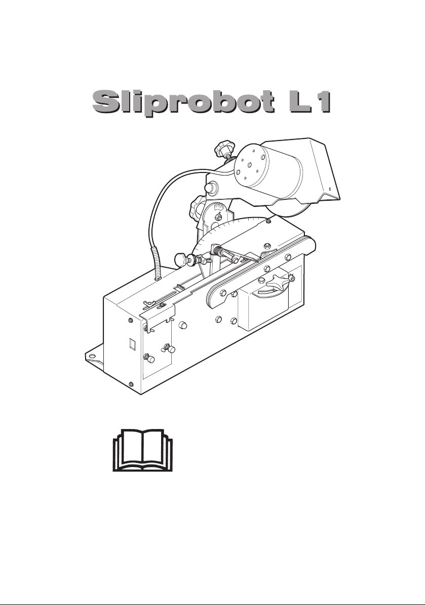
User guide
Before using the machine, read this user guide thoroughly and make sure that you have understood it.
Page 2

CONTENTS
CONTENTS ......................................................................... 2
GENERAL ........................................................................... 3
DESCRIPTION OF FIELD OF APPLICATION.................... 3
SYMBOLS ........................................................................... 4
WARNING STICKERS ........................................................ 4
SAFETY REGULATIONS.................................................... 5
MOTOR DATA - Sliprobot L1 ............................................ 5
POWER SUPPLY ................................................................ 6
FUNCTIONS ........................................................................ 7
INSTALLING THE SHARPENING MACHINE .................... 8
POWER SUPPLY ................................................................ 8
CUTTING ANGLE ............................................................... 8
SHARPENING ANGLE ...................................................... 8
CENTRING THE GRINDING WHEEL ................................. 9
TRIAL SHARPENING ......................................................... 9
SHARPENING CUTTING LINKS ........................................ 10
FOR A DOUBLE LINK, PROCEED AS FOLLOWS ........... 11
SHARPENING SETTING .................................................... 12
GRINDING THE DEPTH GAUGE LUGS ............................ 13
MAINTENANCE .................................................................. 14
CHANGING THE GRINDING WHEEL ........................................................ 14
SETTINGS AND SERVICING .....................................................................15
TROUBLESHOOTING ........................................................ 16
EC DECLARATION OF CONFORMITY..............................19
BASIC TIP ...........................................................................20
There may be discrepancies in the pictures but the information is
always correct.
2
Page 3

GENERAL
This user guide describes in detail how to use, maintain and inspect the chain
sharpening machine. It also describes the steps to be taken to ensure
maximum safety, how the safety components are designed and how they
work and how to check and inspect them. It also explains how to carry out
any repairs that may be needed.
NOTE:
Everyone who will install, use or repair the chain sharpening machine
must read and understand this manual.
The user guide covers installation, operation and the various maintenance
actions that can be done by the operator. More detailed servicing or
troubleshooting must be done by the dealer’s servicing team. The user guide
describes all the necessary safety-related components. Anyone who intends
to use the machine must read and understand it before the chain sharpening
machine is installed. Symbols and warning signs shown in this section appear
in this manual and on the chain sharpening machine.
If a warning decal on the machine has been damaged or is worn, a new one
must be applied as soon as possible to ensure the greatest possible safety
when using the chain sharpening machine.
DESCRIPTION OF FIELD OF APPLICATION
The machine is designed to sharpen cutting saw chains, for example, those on
chainsaw and chainsaw mills.
The machine is design to sharpen the cutting teeth of chains and lugs. It
works automatically.
The machine must be used indoors.
The machine is powered by a 12-volt supply.
3
Page 4
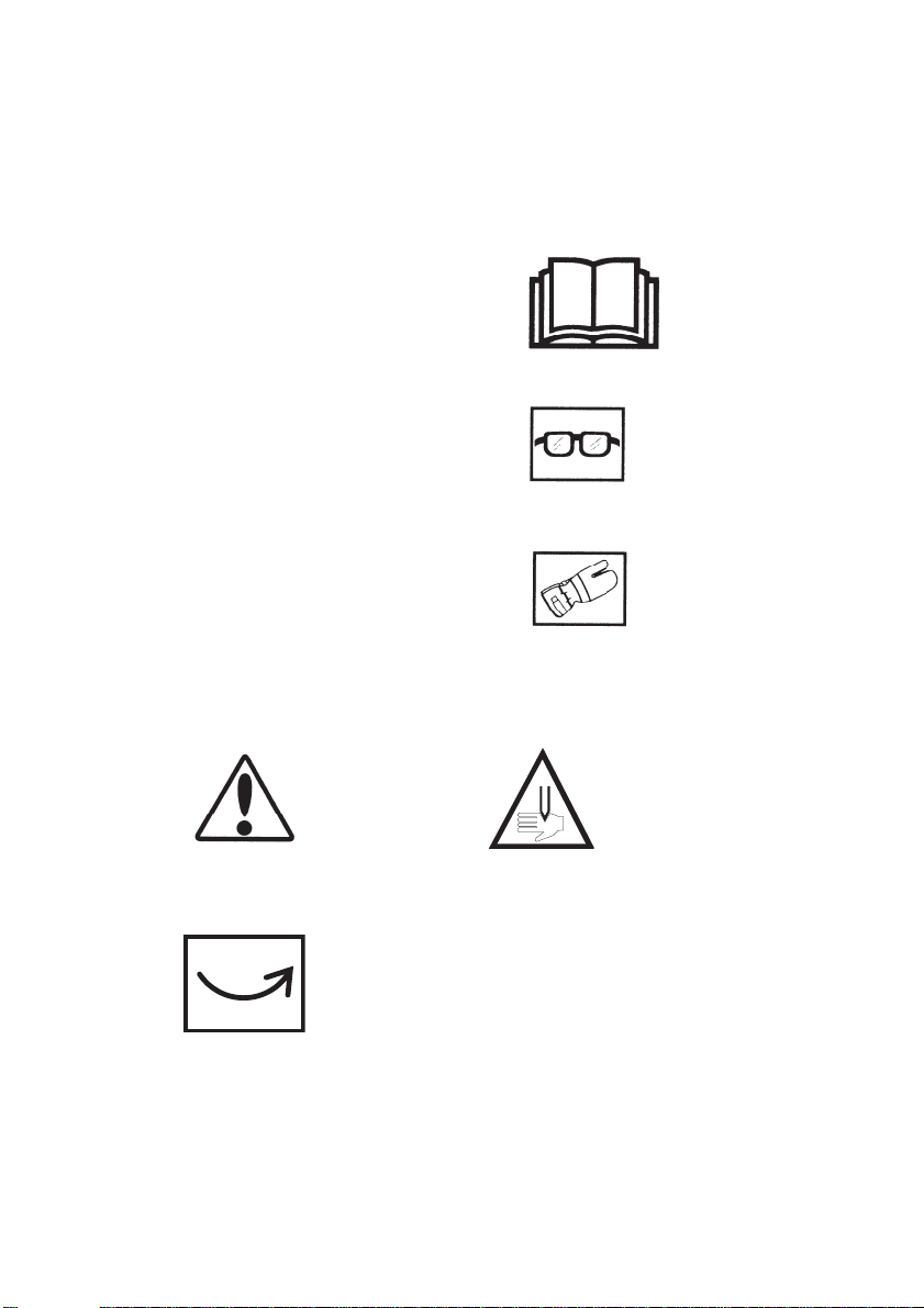
SYMBOLS
Before using the chain sharpening machine, read this user guide thoroughly and make sure that you have understood it all.
Wear eye protection.
Wear safety gloves.
WARNING STICKERS
Caution
Direction of rotation
Risk of cutting injury.
4
Page 5

SAFETY REGULATIONS
Locate the machine where it is not exposed to rain or moisture.
The site must be well lit.
The machine must not be located close to gas, liquids or other materials that
might catch fire or explode.
Only a service technician is permitted to carry out work on the machine.
To avoid mistakes when sharpening chainsaw chains, it is extremely
important to understand how the sharpening machine works.
Read the instruction manual carefully before doing any sharpening with the
machine.
Always wear safety gloves and safety goggles.
Always check the condition of the grinding wheels.
Cracked, vibrating or wobbling grinding wheels must be discarded.
To avoid breakdowns, clean the machine to remove grinding dust.
MOTOR DATA - Sliprobot L1
Grinding motor
Voltage: 12 volts
Rotation speed: 2800 rpm
Peripheral speed: 22 m/s (72ft/s)
Power: 90 watts
Current: 7.5 A
Grinding wheel: 150 x 4 x 16 mm
Overcurrent protection: Miniature circuit-breaker type ptc
Machine: 9 kg (20 lb)
Machine dimensions: L370 x W300 x H350 mm
Working voltage: Min 12 V, max 14 V
5
Page 6
POWER SUPPLY
In order to obtain the best result the machine should be connected to a car battery 12 volt (max 12-14 volt, min 9 ampere).
NOTE:
Battery placement.
Make sure that the battery terminals are connected to the correct poles
of the battery.
Position the battery so that sparks from the sharpening machine cannot
reach it.
1
2
3
4
10
8
9
5
6
7
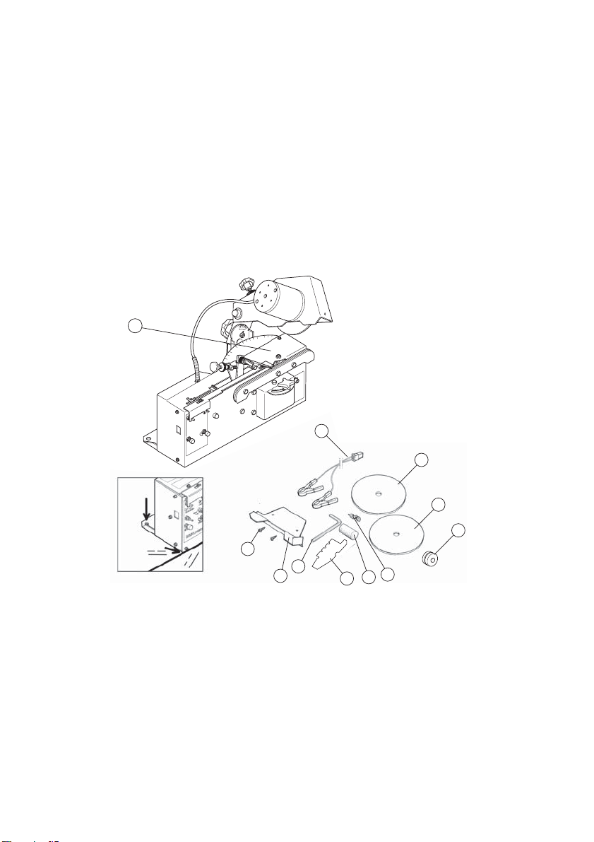
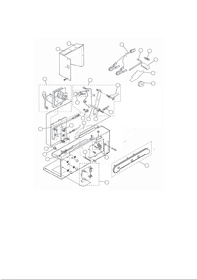
1. Sharpening machine 6. Profile stone
2. Battery cables 7. Profile template (transport support))
3. Grinding wheel 150 x 4 x 16: 8. Allen key
4. Grinding wheel 150 x 4 x 16: 9. Grinding wheel guard:
5. Stop clamp 10. Self-tapping screw x 2
11. Sprocket weight
6
11
Page 7
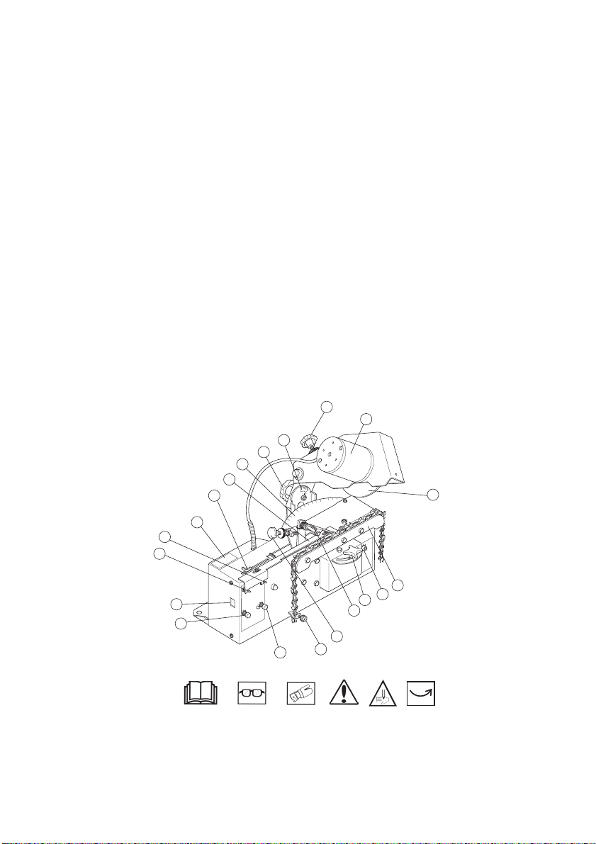
Machine operating controls
1. Start the motor of the sharpening
machine.
2. Start the automatic system. 13. Adjusting the grinding angle 0°- 35°.
4. Electric power (12-14 V DC) in. 14. Grinding wheel.
5. Stop button. (zero-voltage cutou t. When
the power is cut off, the machine must
be started manually.)
7. Power on. 16. Depth adjustment of the grinding
8. Stop clamp 17. The graduated scale shows grinding
9. Cutting tooth length setting adjustment. 18. Knob for adjusting the grinding angle
10. Chain feeder mechanism. 19. The graduated scale shows grinding
11. Centring of length between right and
left cutting tooth.
19
20
21
12. Chain rulers.
15. Grinding motor.
wheel.
angles from 90° to 50°.
between 90° and 50°.
angles from 90° to 35°.
20. Stop arm
21. Stroke adjustment.
22. Symbols
16
15
17
18
14
22
1
2
12
11
4
5
7
13
10
9
8
7
Page 8
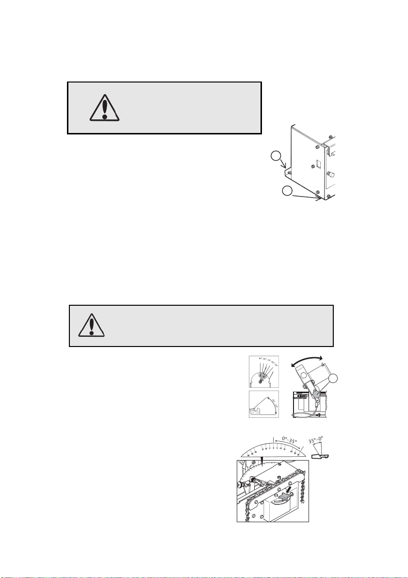
INSTALLING THE SHARPENING MACHINE
F
The machine must not be located close to gas, liquids or other materials that might catch fire or explode.
Install the machine on a bench or stand.
NOTE:
The machine must be securely fixed. 1
1
The machine should be mounted so that the
front edge of it reaches 1-5 mm over the edge
of the bench or stand. 2
2
POWER SUPPLY
For optimum performance, the machine should be connected to a 12-volt car
battery, but it can also be powered from a battery charger or some another
converter with an output of 12 to max 15 volts (at least 10 amps).
Connect appropriate cables to the terminals of the sharpening machine.
Connect the red cable to + and the black to -.
If the cables are switched the grinding machine will not work.
Check that the direction of rotation agr ees with the arrow on the grinding wheel guard.
The grinding wheel must not be running when the
sharpening machine is being set up. The incoming power
must always be switched off when during set up.
CUTTING ANGLE
The cutting angle can be varied between 90°
°. Slacken knob 18. Turn the grinding
and 50
head to the correct degree marking and
tighten the knob. Fig A.
ig A
18
GRINDING ANGLE
The grinding angle can be set from 0°-35°.
Loosen the knob to change. Turn the grinding
head to the desired angle on the degree scale.
Tighten the knob. Fig B.
30
35
8
35
30
25
15
10
5
0
5
10
15
25
Fig B
Page 9
CENTRING THE GRINDING WHEEL
35
30
5
0
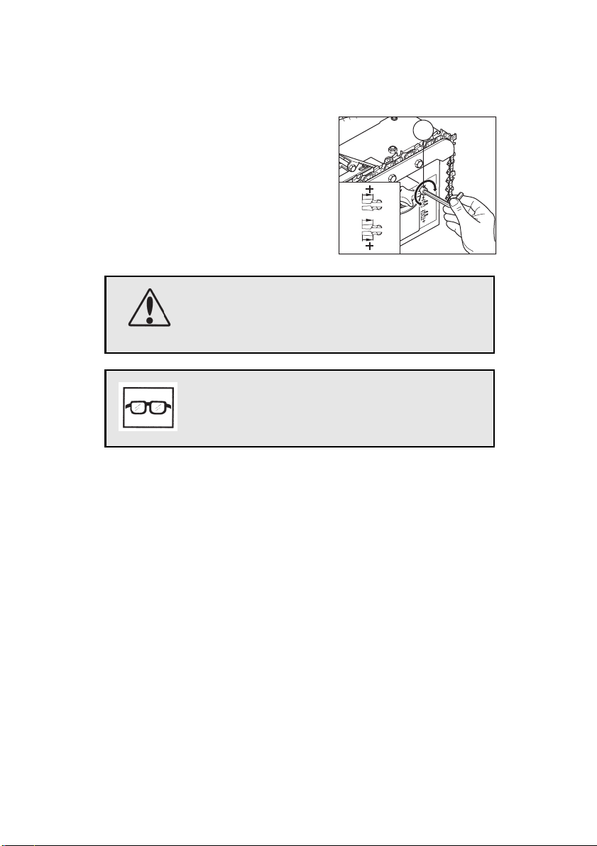
If the lengths of the right and left cutting links
2
15
10
5
11
turn out different on sharpening, this can be
adjusted with adjusting screw 11. When the
screw is adjusted, the length of the inner or
outer cutting links increases.
Be ready to stop the machine if something goes wrong during trial sharpening.
Check that the grinding wheel is not cracked and that it is securely fixed to the spindle. Stop the grinding wheel immediately if abnormal vibrations occur.
TRIAL SHARPENING
Test the various functions of the machine and study its motions.
Always stop the machine when the grinding head reaches its uppermost
position. The chain rulers are then “unlocked” and the chain is free. When
you have done a trial run with the machine and feel familiar with it, you can
put in a chain. Now test-sharpen a chain, following the instructions in the
section Sharpening cutting links. In the interest of safety, use an old chain.
9
Page 10
SHARPENING CUTTING LINKS
Always wear safety gloves when handling saw chains. Risk of cutting injury.
With manual or automatic shoutdown. The machine can be stopped
manually without a stop clamp when sharpening is complete, or with
a stop clamp as described below.
Activate Power on, switch 7
Start grinding motor only with switch 1.
Using profile stone 7, profile the grinding wheel for the type of chain to be sharpened,
as shown in Figure H. Check with profile template 6.
Stop the grinding motor with switch 1.
Place the chain to be sharpened between chain rulers 8.
Pull the chain around by hand and check that it runs freely in the chain track.
Check also whether the chain has “double links”, that it does not have an y bur rs on the
drive links and that it is not damaged.
NOTE: If there are double links, see the instructions for double links.
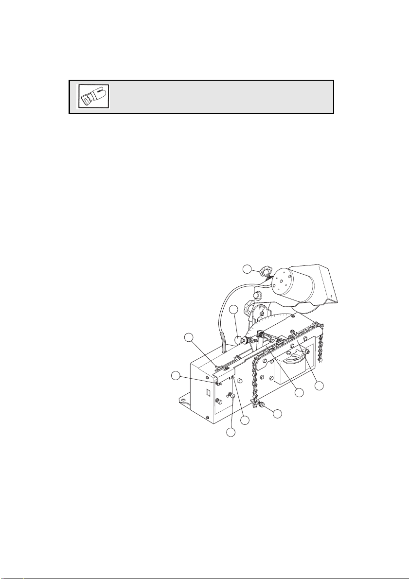
• Check that the grinding head
is square to the teeth.
• Start the automatic system with
switch 2.
• With wingnut 6, set the correct
stroke for the chain to be
sharpened.
• Set the approximate sharpening
depth with wheel 5.
• Set the approximate sharpening
depth with wheel 4.
• Start the grinding motor only
with switch 1.
• Set the sharpening depth finely
with wheel 5.
• Set the sharpening length finely
with wheel 4.
• Stop the automatic system with
switch 2 and the motor with
switch 1.
• Then fix clamp 9, see Fig F,
after the first or last sharpened
tooth.
• Let the machine run one
revolution to clamp 9. Fig F.
Stop the machine against stop
arm 20.
6
2
5
4
8
20
1
7
9
10
Page 11

FOR A DOUBLE LINK, PROCEED AS FOLLOWS
Sharpen the other (2) (Fig E) of the two links on the same side, double links
2.3.
Stop the automatic system with switch 2.
Fix the clamp 1 (Fig F) between the two double links 2.3.
Start the automatic system with switch 2 and the motor with switch 1.
Let the machine run one revolution to clamp 9 (Fig. F). Stop the machine
using the stop arm 20.
FigE
FigF
9
11
2
3
Page 12
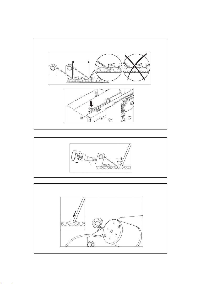
SHARPENING SETTING
Setting the stroke between the cutting links.
(Slacken the wingnut and push it to the right for a shorter stroke.)
Adjust the cutting tooth length setting. (Clockwise = shorter cutting tooth)
Depth adjustment of the grinding wheel. (Anticlockwise=deeper grinding into the cutting tooth).
12
Page 13
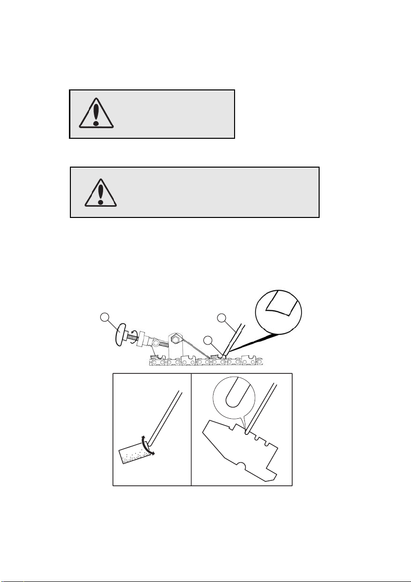
GRINDING THE DEPTH GAUGE LUGS
The incoming power must always be switched off.
Set the grinding angle (o° degrees); see under Grinding angle.
Check that the grinding wheel is not cracked and
that it is securely fixed to the spindle.
Stop the grinding wheel immediately if abnormal
vibrations occur.
Install the correct grinding wheel 1 (Fig G) for grinding the depth gauge
lugs (6 mm). Profile the grinding wheel so that it matches the lugs 2.
Adjust 3 back so that the grinding wheel 1 is aimed at the lug 2. (Apart from
this, perform the adjustment in the same way as when adjusting the grinding
of cutting links).
3
Fig H
1
2
13
Page 14
MAINTENANCE
F
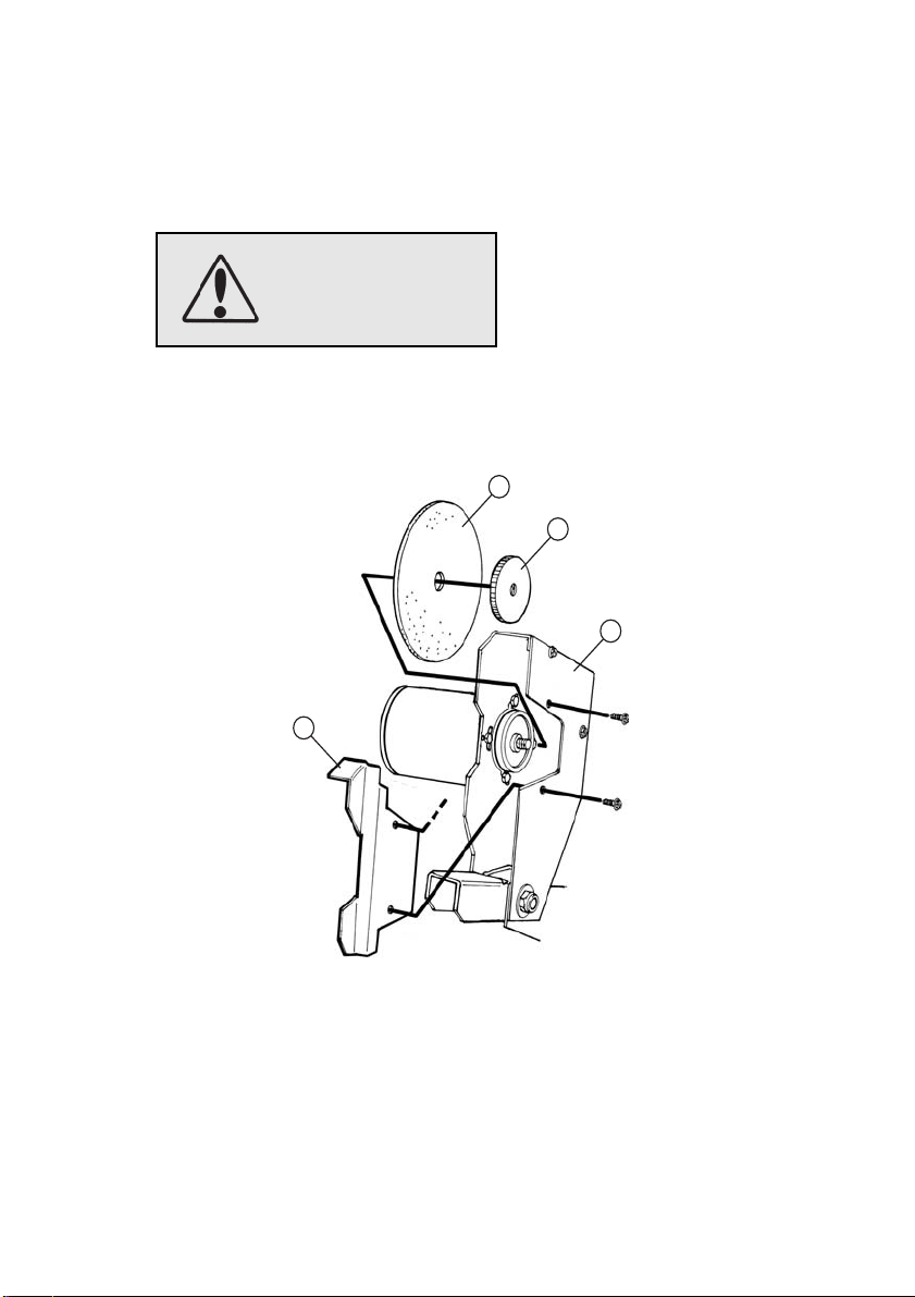
CHANGING THE GRINDING WHEEL
The incoming power must always be switched off.
1. Lift up the grinding head (1) and remove the guard (9).
2. Hold the grinding wheel (2) and slacken the nut (3) manually or with
pliers.
3. Remove the old grinding wheel and fit the new one. Hand-tighten the nut
2
3
1
9
ig G
14
Page 15
SETTINGS AND SERVICING
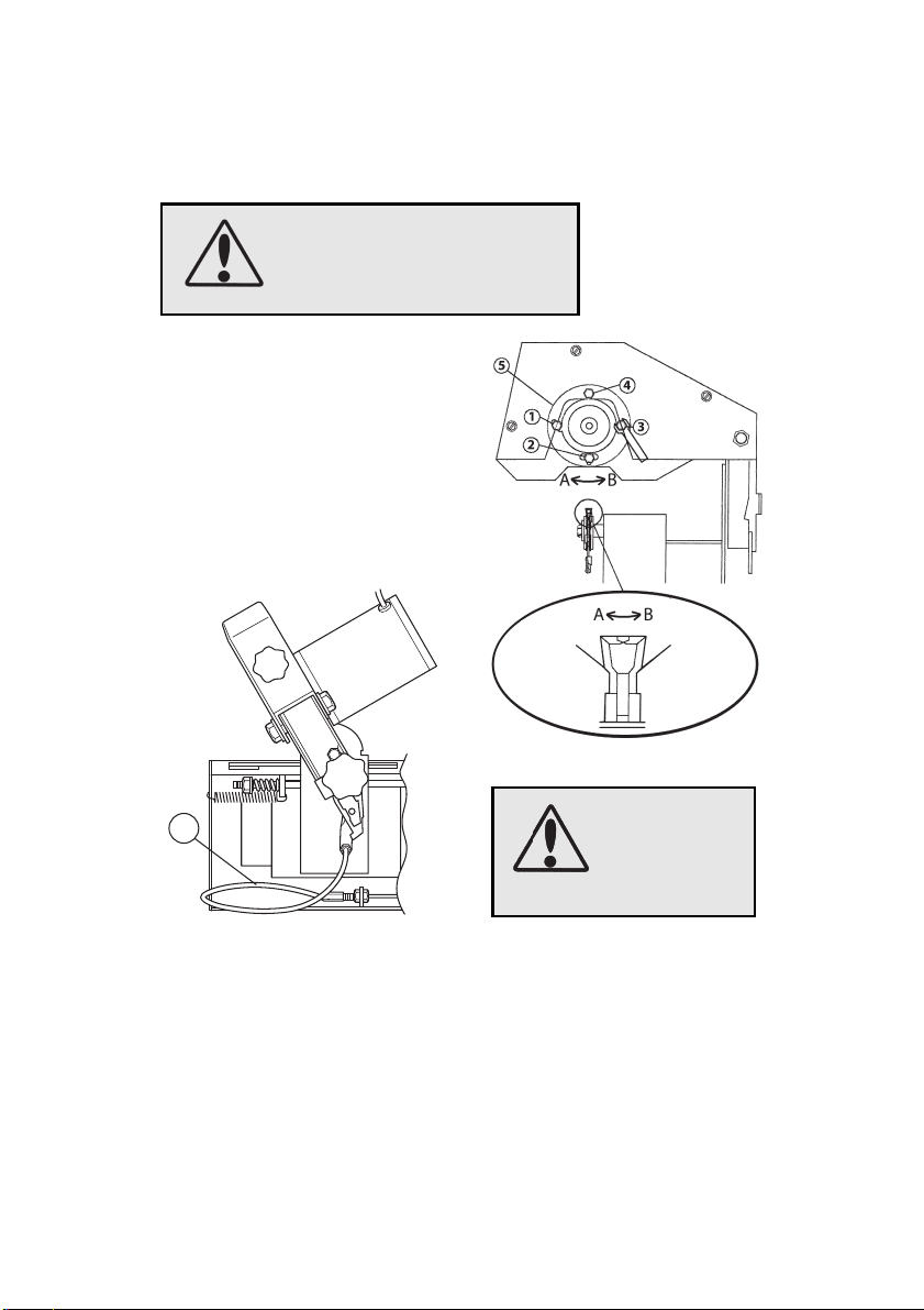
The incoming power must always be switched off.
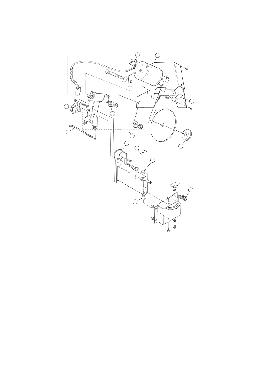
If one cutting link gets too deep or too
shallow, this can be changed by
slackening screw 1, 2, 3 or 4 and
turning motor 5 as shown.
Turn the motor in the relevant
direction and tighten the screws.
The machine is largely maintenancefree, but it should be kept clean by
removing any grinding dust.
3
The wire (3) must be inspected after 40 hours’ running to check that it is not in poor condition and that its tension is correct.
15
A = Deeper grinding
on this cutting
link.
B = Deeper grinding
on this cutting
link.
Replace the wire immediately if it is in a poor condition.
Page 16
TROUBLESHOOTING
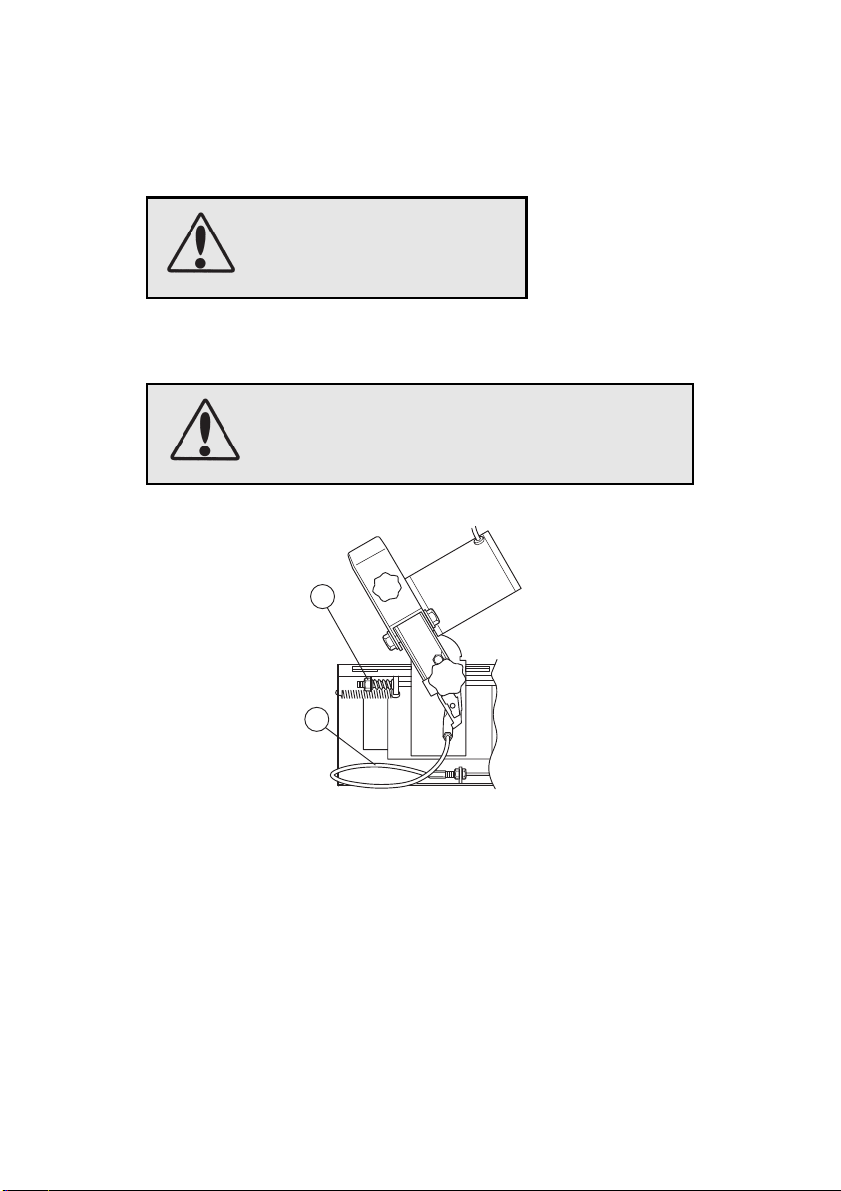
The incoming power must always be switched off.
The chain is not fixed during sharpening (Fig. I). Tighten M6 nut (1) clockwise about one turn, or more if necessary.
More thorough servicing or troubleshooting must be done by the dealer’s servicing team.
1
3
16
Page 17
25
24
23
13
14
21
22
16
18
17
15
1
2
3
4
5
20
19
6
12
11
10
15
8
7
9
17
Page 18
2
3
13
11
12
1
10
9
8
8
4
5
7
18
Page 19

EC DECLARATION OF CONFORMITY
Manufacturer:
Markusson Development Systems AB
Tegelbruksvägen
762 31 Rimbo, Sweden
hereby declares that:
Sliprobot L1
Logosol Sliprobot L1
has been manufactured in compliance with the following EC directives:
98/37 EC, The Machine Directive 73/23 EEC as amended, The Low-Voltage Directive 89-336/EEC as amended, The EMC Directive
The following standards were used as a basis for this declaration.
EN ISO 12100-1, -2
EN 61000-6-3, EN 55014-1, -2
Signed:
CEO: Pär Markusson
Company:
Markusson Development Systems AB
Tegelbruksvägen
762 31 Rimbo, Sweden
Date: 2006-06-15
Place: Rimbo Sweden
Sign:
19
Page 20
Basic tips:
35
30
5
0
Cutting angle, see page 8 in the operator's manual. In most cases we
recommend to grind at 60 degrees or from 50 to max 75 degrees. This also
applies if the chain manufacturers recommend other settings.
Sharpening settings, see page 12 in the operator's manual.
The stroke length setting is changed by loosening the wing nut. Now slide the
plate that controls the stroke length so that the front feeder arm falls down
approximately 2 mm behind the cutting tooth to be fed forward. Tighten the
wing nut.
Dressing the grinding wheel, see page 13 in the operator's manual. Before
sharpening the cutting links, dress the periphery of the grinding wheel so it
has an even radius. The grinding wheel must be round before sharpening and
correspond to the round file intended to sharpen the equivalent chain. Check
against the supplied dressing gauge (which also acts as a transport support).
The supplied sprocket weight can ideally be used as a weight on the chain to stretch it when sharpening. It is beneficial if the chain is slightly “tight”.
This grinder can sharpen most available saw chains, but not 404 chains designed for logging machines.
2
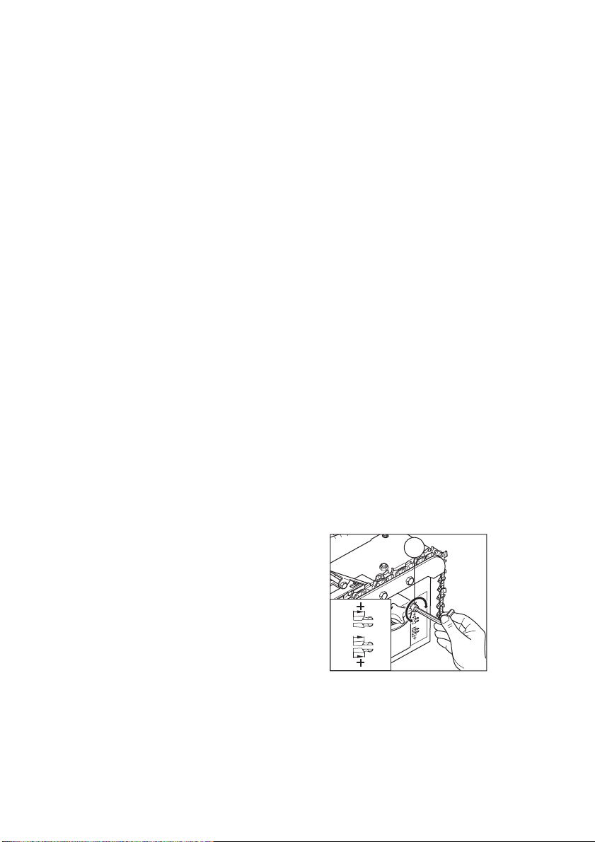
Equally long cutting links, see page 9
in the operator's manual (CENTRING
15
10
5
11
THE GRINDING WHEEL). If the
right and left-hand cutting links are of
different lengths after they have been
sharpened, this is adjusted using the
adjuster screw, 11. When adjusting the
adjuster screw the length of the inner
and outer cutting links decreases
respective increases.
 Loading...