

Page 1
Page 2

Software/Manual application Information:
Note: This manual is to be used only with models A, B, C & D ventilators using the
following software version:
VERSION 4.1 ENGLISH / ENGLISH
Contact Information:
SLE Limited
Twin Bridges Business Park
232 Selsdon Road
South Croydon
Surrey CR2 6PL
Telephone: +44 (0)20 8681 1414
Fax: +44 (0)20 8649 8570
E-mail: [email protected]
Web site: www.sle.co.uk
(E-mail’s should be addressed to the Service Manager)
All rights reserved. No part of this publication may be reproduced, stored in any retrieval system, or transmitted
in any form or by any means, electronic, mechanical, photocopy, recording or otherwise, without prior
permission of SLE. © Copyright SLE 10/04/2006.
Manual : UM0083 Issue 6
SLE Part Nº: N6626/05 .
Page 2 of 292
Page 3

How To Use The
SLE5000/SLE4000 Infant Ventilator
The warnings on pages 28 to 32 must be read and understood
before using the SLE5000/SLE4000 ventilator. Failure to do so
could lead to injury or death of the patient.
1 MAKE SURE THAT THE VENTILATOR BACK-UP POWER
SUPPLY IS FULLY CHARGED: Page 134.
2 PERFORM THE FUNCTIONAL TESTS: Page 94.
3 SETUP THE VENTILATOR IN THE CHOSEN MODE: Page 154.
4 THE VENTILATOR IS READY FOR USE.
For more information see technical section, page 214.
For trouble shooting see troubleshooting chart, page 200.
Page 3 of 292
Page 4

This page is intentionally blank.
Page 4 of 292
Page 5

Contents
1. Introduction ...............................................................................................................14
1.1. About This Manual ...........................................................................................14
1.2. Intended Use ....................................................................................................14
1.2.1. Intended Users ..........................................................................................14
2. Description of the Ventilation Modes ......................................................................15
2.1. CPAP................................................................................................................15
2.1.1. CPAP with Apnoea Backup .......................................................................15
2.1.2. CPAP with TTV (Targeted Tidal Volume) for Back Up Breaths................. 15
2.2. CMV .................................................................................................................16
2.2.1. CMV with TTV ...........................................................................................16
2.3. PTV ..................................................................................................................17
2.3.1. PTV with TTV ............................................................................................18
2.4. PSV ..................................................................................................................19
2.4.1. PSV with TTV ............................................................................................20
2.5. SIMV (Synchronized Intermittent Mandatory Ventilation).................................21
2.5.1. SIMV with PSV ..........................................................................................22
2.5.2. SIMV with TTV...........................................................................................23
2.6. HFO (SLE5000 only) ........................................................................................23
2.7. HFO+CMV (SLE5000 only) ..............................................................................23
2.8. Mode controls...................................................................................................24
2.8.1. TTV Control Mode .....................................................................................24
2.9. Technical Description .......................................................................................25
3. User/Owner Responsibility ......................................................................................26
4. Warnings ....................................................................................................................28
4.1. Operational Warnings.......................................................................................28
4.2. Clinical Warnings..............................................................................................31
5. Ventilator Description ...............................................................................................34
6. Description of Symbols and Buttons ......................................................................37
7. User Interface ............................................................................................................44
7.1. User Interface Sections ....................................................................................44
7.2. Description of User Interface Indicators ...........................................................45
7.3. Description of User Interface Controls..............................................................45
7.3.1. Examples of Control Use ...........................................................................46
7.4. Description of the Mode Panel in Ventilation Off Mode....................................48
7.4.1. Mode Panel in Ventilation Off Mode ..........................................................48
7.4.2. Mode Select Button ...................................................................................48
7.4.3. Oxygen Alarm Test ....................................................................................49
7.5. Services Panel .................................................................................................49
7.5.1. Flow ...........................................................................................................50
7.5.2. Oxygen ......................................................................................................50
7.5.3. Wave Shaping ...........................................................................................50
7.5.4. Alarm Volume ............................................................................................51
Page 5 of 292
Page 6

7.6. More Options Panel ......................................................................................... 51
7.6.1. Language Toggle ...................................................................................... 52
7.7. Version Information Panel................................................................................ 53
7.7.1. Monitor Services........................................................................................ 54
7.7.2. Controller Services .................................................................................... 54
7.8. Mode Panel Functions in a Ventilation Mode................................................... 55
7.8.1. Standby Button (All modes)....................................................................... 55
7.8.2. Apnoea Setup for CPAP............................................................................ 56
7.8.3. Apnoea Setup for PTV, PSV and SIMV .................................................... 56
7.8.4. TTV for CPAP, PSV, PTV & SIMV ............................................................ 57
7.8.5. Set Trigger for CPAP, PSV, PTV & SIMV ................................................. 57
7.8.6. Pressure Support in PSV .......................................................................... 57
7.8.7. Pressure Support in SIMV......................................................................... 58
7.8.8. HFO Activity (SLE5000 Only).................................................................... 58
7.9. Alarm Panel ..................................................................................................... 59
7.10. Default Waveform Windows........................................................................... 60
7.11. Alarm and Breath Detection Thresholds ........................................................ 62
7.12. How to Set an Alarm Threshold ..................................................................... 63
7.13. Ventilation Parameters................................................................................... 66
7.14. Lung Mechanics and Measurement Panel..................................................... 68
7.15. The Pause Button .......................................................................................... 70
7.16. Night Button and Screen Lock ....................................................................... 70
8. Loops, Trends & Waveforms ................................................................................... 72
8.1. Waveforms....................................................................................................... 72
8.2. Loops ............................................................................................................... 74
8.2.1. Storing and Retrieving Loops. ................................................................... 74
8.3. Trends.............................................................................................................. 76
8.3.1. Description of Trend Windows .................................................................. 76
9. Ventilator Set-up ....................................................................................................... 78
9.1. Preparing the Ventilator for Use....................................................................... 78
9.2. Setup Related Items ........................................................................................ 82
9.2.1. Shutting Down of the Ventilator................................................................. 82
9.2.2. Back-up Battery Charging ......................................................................... 82
10. Quick Setup ............................................................................................................ 84
10.0.1. Complete Power Fail Alarm Test............................................................. 85
10.0.2. Calibration of the Flow Sensor ................................................................ 86
10.0.3. Low Oxygen Alarm Test .......................................................................... 87
10.0.4. Apnoea Alarm.......................................................................................... 89
10.0.5. Leak / Block Alarm .................................................................................. 90
10.0.6. High Pressure Alarm ............................................................................... 90
10.0.7. Low Tidal Volume.................................................................................... 90
10.0.8. Functional Test of HFO+CMV Mode ....................................................... 91
11. Functional Testing ................................................................................................ 94
11.1. Stage 1 Functional testing ............................................................................. 95
Page 6 of 292
Page 7

11.1.1. Complete Power Fail Alarm Test. ............................................................95
11.1.2. Setting FiO2.............................................................................................96
11.1.3. Functional Testing with No Flow Sensor .................................................96
11.1.4. Calibration of the Flow sensor .................................................................96
11.1.5. Oxygen Alarm Test ..................................................................................98
11.1.6. Function and Alarm Testing.....................................................................100
11.1.7. High Pressure Alarm................................................................................104
11.1.8. Low Alarm................................................................................................104
11.1.9. Breath Not Detected Alarm......................................................................105
11.1.10. Leak / Block Alarm.................................................................................106
11.1.11. Mains Failure Alarm...............................................................................106
11.1.12. Gas Supply Alarms ................................................................................107
11.1.13. Flow Sensor Disconnect Alarm..............................................................108
11.1.14. Cycle Fail Alarm.....................................................................................108
11.1.15. Functional Test of HFO Mode................................................................110
11.1.16. Functional Test of HFO+CMV Mode......................................................112
11.1.17. Pressure Change Alarm ........................................................................114
11.2. Stage 2 Functional testing..............................................................................115
11.2.1. Functional Test of CMV Mode .................................................................115
11.2.2. Functional Test of PSV Mode ..................................................................120
11.2.3. Functional Test of SIMV Mode ................................................................123
12. Stage 1 Check List ..................................................................................................129
13. Stage 2 Check list ...................................................................................................131
14. Operational Considerations ...................................................................................134
14.1. General...........................................................................................................134
14.1.1. Ventilation Off Mode ................................................................................134
14.1.2. Gas Input Pressures ................................................................................134
14.1.3. Mode Memory On Power Up ...................................................................134
14.1.4. Back Up Battery Power............................................................................134
14.1.5. Parameter Memory ..................................................................................135
14.1.6. BPM or Backup, Measured and Set Parameters.....................................135
14.1.7. Tidal Volume Parameter Resolution ........................................................135
14.1.8. HFO, Mean and Delta P Parameters.......................................................135
14.1.9. Displayed FiO2.........................................................................................135
14.1.10. Breath Detection ....................................................................................136
14.1.11. Max Ti in PSV ........................................................................................136
14.1.12. TTV (Targeted Tidal Volume) ................................................................136
14.1.13. Overshoot ..............................................................................................137
14.1.14. Wave Shaping .......................................................................................137
14.1.15. Circuit Disconnection Procedure ...........................................................138
14.1.16. BPM Tot. Measurement.........................................................................139
14.2. Alarms ............................................................................................................140
14.2.1. High and Low Alarm Operation................................................................140
14.2.2. Minute Volume Alarm Threshold .............................................................141
14.2.3. Cycle Fail Alarm Threshold......................................................................141
14.2.4. Sub-ambient Pressure Alarm in Non HFO Modes...................................141
Page 7 of 292
Page 8

14.2.5. HFO Only Ventilator Set Threshold Alarms (SLE5000 only)................... 142
14.2.6. Patient Leak Alarm .................................................................................. 143
14.2.7. Reset Contamination Alarm .................................................................... 143
14.3. Patient Circuits, Humidification and Nitric Oxide Therapy ............................. 144
14.3.1. Patient Circuits with Incubators, Cots and Paediatric beds..................... 144
14.3.2. Autofeed Humidification chambers.......................................................... 145
14.3.3. Nitric Oxide Therapy................................................................................ 146
14.3.4. Nebulization of Medication ..................................................................... 147
15. Flow and Pressure Triggering ............................................................................... 150
15.1. Breath Detection Threshold (Flow Triggering) ............................................... 150
15.2. Breath Trigger Sensitivity (Pressure Triggering)............................................ 151
15.3. Setting the Pressure Trigger Level in CPAP, SIMV, PTV and PSV............... 152
16. Basic Set-up ............................................................................................................ 154
16.1. Pre Set-up Checks......................................................................................... 154
16.2. Setting the FiO2............................................................................................. 155
16.3. CPAP Set-up.................................................................................................. 156
16.3.1. Actions After Connection to Patient in CPAP .......................................... 157
16.3.2. Ventilation Without a Flow Sensor Connected. ....................................... 159
16.4. CMV Set-up ................................................................................................... 160
16.4.1. Actions After Connection to Patient in CMV............................................ 161
16.4.2. Ventilation Without a Flow Sensor Connected. ....................................... 162
16.5. PTV Set-up .................................................................................................... 163
16.5.1. Actions after connection to patient in PTV .............................................. 164
16.5.2. Ventilation Without a Flow Sensor Connected. ....................................... 166
16.6. PSV Set-up .................................................................................................... 167
16.6.1. Actions After Connection to Patient in PSV............................................. 168
16.6.2. Ventilation Without a Flow Sensor Connected. ....................................... 170
16.7. SIMV Set-up................................................................................................... 171
16.7.1. Actions After Connection to Patient in SIMV ........................................... 172
16.7.2. Ventilation Without a Flow Sensor Connected. ....................................... 175
16.8. HFO Only Set-up (SLE5000 only).................................................................. 176
16.8.1. Actions After Connection to Patient in HFO ............................................ 177
16.8.2. Ventilation Without a Flow Sensor Connected. ....................................... 177
16.9. HFO+CMV Set-up (SLE5000 only) ................................................................ 178
16.9.1. Actions After Connection to Patient in HFO+CMV .................................. 179
16.9.2. Ventilation Without a Flow Sensor Connected. ....................................... 179
17. N5201 Flow Sensor ................................................................................................ 182
17.1. Calibration of the Flow Sensor....................................................................... 182
17.2. Cleaning and Sterilization .............................................................................. 184
18. Frequently Asked Questions ................................................................................. 188
18.1. Ventilator Related Questions ......................................................................... 188
18.1.1. What range of patients is the ventilator designed to ventilate? ............... 188
18.1.2. Can the ventilator be used without a flow sensor?.................................. 188
18.1.3. How often must the flow sensor be calibrated?....................................... 188
Page 8 of 292
Page 9

18.1.4. What does “SENSOR CONTAMINATION” mean?..................................188
18.1.5. What is Standby mode used for?.............................................................188
18.1.6. What happens when the Pause button is pressed? ................................189
18.1.7. What is the operating time of the battery? ...............................................189
18.1.8. What is the battery charging time? ..........................................................189
18.1.9. What is the difference between PTV and PSV? ......................................189
18.1.10. When looking at the parameter settings, what do I record? ..................189
18.1.11. Where do I set the Trigger Sensitivity?..................................................189
18.2. Mode Related Questions................................................................................190
18.2.1. What is meant by Targeted Tidal Volume?..............................................190
18.2.2. What are appropriate Tidal Volumes? .....................................................190
18.2.3. What is the meaning of Compliance and Resistance? ............................190
18.2.4. How do I minimise the Apnoea alarm in CPAP? .....................................190
18.2.5. In TTV some of the breaths exceed the set TTV. Why?..........................190
18.2.6. Why is there no SET value for MAP and dp in HFO mode?.................... 191
18.3. Patient Circuits ...............................................................................................191
18.3.1. What is the difference between the N2188 and N5188 patient circuit? ... 191
18.3.2. Why is a restrictor necessary?.................................................................191
18.3.3. What is a /02 patient circuit?....................................................................191
18.3.4. What is a /850 patient circuit?..................................................................191
18.3.5. What happens if the restrictor is placed in the expiratory limb instead
of the inspiratory limb?..........................................................................................191
18.3.6. Should bacterial filters be used on the expiratory limb? ..........................191
18.3.7. When using the INOSYS Nitric Oxide therapy and the ventilator what
scavenging filters do I need? ................................................................................191
18.3.8. How often does the exhalation block and silencer need to be
autoclaved? ..........................................................................................................192
18.3.9. How do I clean the exhalation block and scavenging system after using
NO? ......................................................................................................................192
19. Commonly Seen Alarms .........................................................................................194
19.0.1. High Pressure Alarm................................................................................194
19.0.2. Low Pressure Alarm ................................................................................194
19.0.3. Breath Not Detected ................................................................................194
19.0.4. Low Tidal Volume ....................................................................................194
19.0.5. Unexpected Rise or drop in Mean P (SLE5000 only) .............................. 195
19.0.6. Unexpected Rise or Drop in Max P (SLE5000 only)................................195
19.0.7. Unexpected Rise or Drop in Min P (SLE5000 only).................................195
19.0.8. Continuing Positive Pressure...................................................................195
19.0.9. Leaking Fresh Gas ..................................................................................195
19.0.10. High Patient Leak ..................................................................................196
19.0.11. Clean Flow Sensor ................................................................................196
19.0.12. Faulty Flow Sensor ................................................................................196
19.0.13. Calibration Fail.......................................................................................197
19.0.14. Calibrate Flow Sensor ...........................................................................197
19.0.15. Apnoea (volume) ...................................................................................197
Page 9 of 292
Page 10

20. Trouble Shooting Chart ......................................................................................... 200
20.1. Ventilator Related Problems .......................................................................... 200
20.2. Ventilation Related Problems......................................................................... 209
21. Oxygen Calibration Routines ................................................................................ 214
21.1. One Point O2 Calibration ............................................................................... 214
21.2. Two Point O2 Calibration ............................................................................... 214
22. Preventative Maintenance and Overhaul Schedule ............................................ 215
23. RS232 ......................................................................................................................216
23.1. Warnings for RS232....................................................................................... 216
23.2. Location of RS232 Port.................................................................................. 216
23.3. Overview ........................................................................................................ 217
23.3.1. Data and Pinout Description.................................................................... 217
23.3.2. Cable ....................................................................................................... 217
23.3.3. Parameter Descriptions and Format ....................................................... 218
23.3.4. List of Parameters ................................................................................... 218
23.3.5. Table of Current Alarm Condition Codes. ............................................... 221
23.4. RS232 Connection Settings and Testing Data Output................................... 223
24. Alarms .....................................................................................................................224
24.1. Alarm Protocols.............................................................................................. 224
24.2. Alarm Sounds ................................................................................................ 224
24.3. Alarm Descriptions and Actions to be Taken ................................................. 225
24.4. Software and System Fail Protocols .............................................................. 244
25. Bacterial Filters ...................................................................................................... 245
25.1. Bacterial filter, SLE Part Nº:N2029 (Autoclavable) ........................................ 245
25.2. Bacterial filter, SLE Part Nº: N2587 (Single use) ........................................... 246
25.2.1. Precautions When Using Bacterial Filter N2587 ..................................... 246
26. Patient Circuits ....................................................................................................... 247
26.1. Warnings for Patient Circuit Use. ................................................................... 247
26.2. 10mm Diameter Re-usable Patient Circuit (SLE Part Nº N2391/50) ............. 248
26.2.1. Sterilising of the N2391/50 re-usable Patient Circuit............................... 248
26.3. 10mm Patient Circuit, SLE Part Nº N5188 & N5188/850.............................. 250
26.4. 10mm Patient Circuit, SLE Part Nº N5188/02 & N5188/02/850..................... 252
26.5. N5238/50 Heated Patient Circuit For NO Therapy ........................................ 254
26.6. Nitric Oxide Delivery Adaptor Kit (SLE Part Nº N2238/50) ............................ 256
27. Cleaning, Disinfection and Sterilization ............................................................... 257
27.1. Preparation of a New Ventilator ..................................................................... 257
27.2. Cleaning and Disinfection of an In-service Ventilator .................................... 257
27.2.1. Cleaning, Disinfection & Sterilization Chart............................................. 258
27.3. Cleaning Method............................................................................................ 258
27.4. Disinfection Method ....................................................................................... 259
27.5. Sterilization Method ....................................................................................... 260
Page 10 of 292
Page 11

28. Technical Specification ..........................................................................................261
28.1. Operating Modes Conventional Ventilation ....................................................261
28.1.1. CPAP .......................................................................................................261
28.1.2. CMV.........................................................................................................261
28.1.3. PTV..........................................................................................................261
28.1.4. PSV..........................................................................................................262
28.1.5. SIMV ........................................................................................................262
28.2. HFO Ventilation ..............................................................................................262
28.2.1. HFO Only.................................................................................................262
28.2.2. HFO+CMV ...............................................................................................262
28.2.3. Controls (Via touch screen display) .........................................................263
28.2.4. Controls ...................................................................................................266
28.3. Measurement .................................................................................................266
28.3.1. Flow and Volume .....................................................................................266
28.3.2. Oxygen Concentration .............................................................................266
28.3.3. Pressure ..................................................................................................267
28.4. Alarms ............................................................................................................268
28.4.1. User settable Alarms ...............................................................................268
28.4.2. Obligatory Alarms (non adjustable by user).............................................269
28.5. Patient circuits ................................................................................................269
28.6. Outputs...........................................................................................................270
28.7. Gas supplies...................................................................................................271
28.7.1. Oxygen supply .........................................................................................271
28.7.2. Air supply .................................................................................................271
28.7.3. Flows .......................................................................................................271
28.8. Power, Dimensions, Standards etc. ...............................................................272
28.9. Environmental Storage Conditions.................................................................272
29. Pneumatic Unit Schematic .....................................................................................273
30. Ventilator Labelling .................................................................................................274
30.1. SLE4000.........................................................................................................274
30.2. SLE5000.........................................................................................................275
31. Consumables and Accessories .............................................................................278
32. Glossary of Abbreviations Used in this Manual ..................................................284
33. Index .........................................................................................................................287
Page 11 of 292
Page 12

This page is intentionally blank.
Page 12 of 292
Page 13

Introduction
Page 13 of 292
Page 14
1. Introduction
1.1 About This Manual
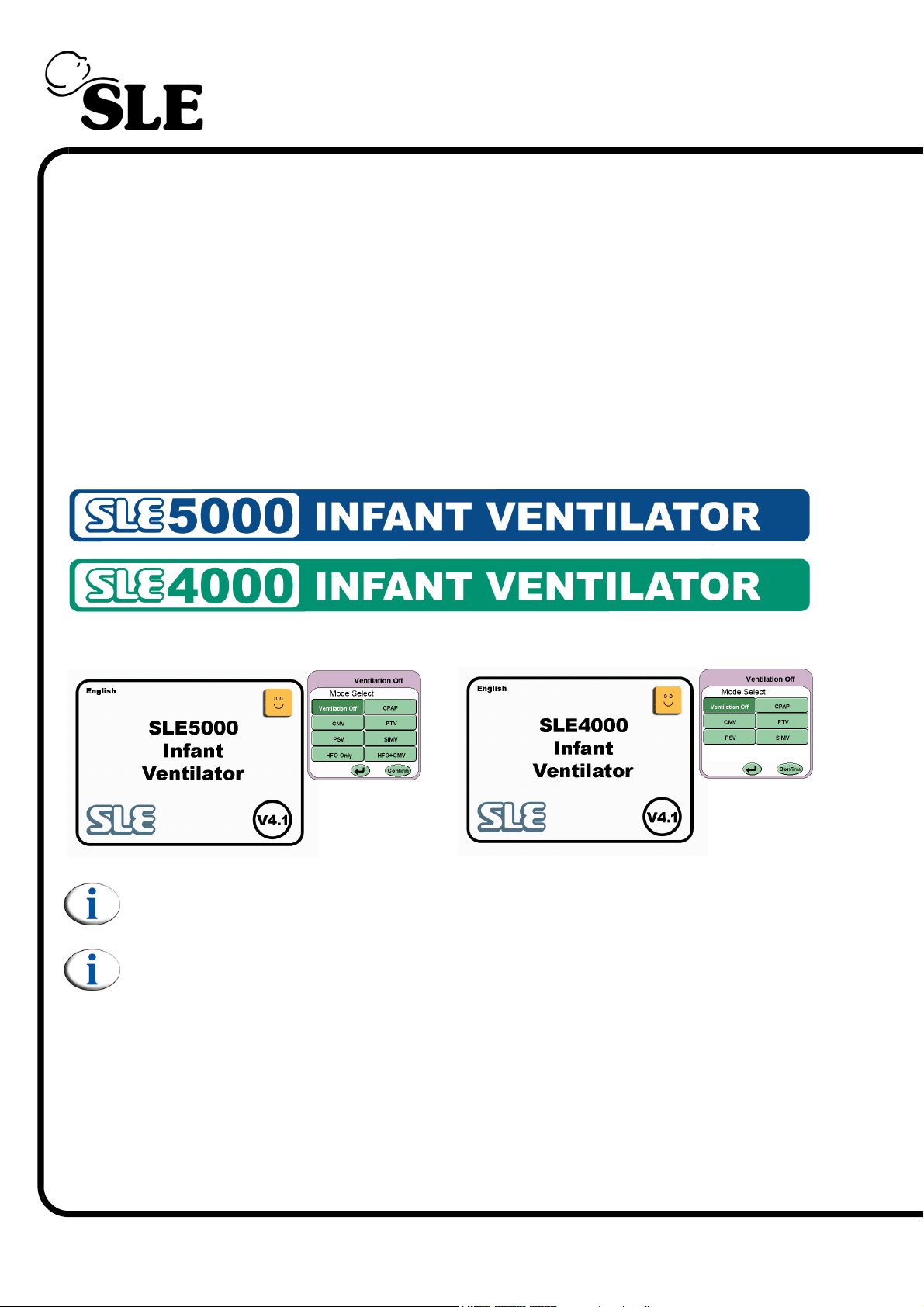
This user manual details the operation of the SLE4000 and SLE5000 infant ventilators. The
difference between an SLE4000 and SLE5000 ventilator is that the SLE5000 has two extra
modes of operation, these being HFO and HFO+CMV.
The user manual will from this point onwards refer to the SLE4000 and SLE5000 as
“the ventilator”.
Where the user manual details an operation or mode: specifically HFO or HFO+CMV then a
statement will appear stating, “SLE5000 only”.
The SLE4000 and SLE5000 model A infant ventilators are identical except for the following,
A. Overlays. (SLE5000 overlays are blue, SLE4000 overlays are green).
B. Installed software. (Start up screens and Mode select panels.)
Note: HFO and HFO+CMV modes are not available on the SLE4000 infant
ventilator.
Note: All the graphics within this manual have been produced with the N6647
test lung and are not representaive of actual clinical data.
1.2 Intended Use
The ventilator is designed for use on patients up to 20kg, in conventional ventilation. In high
frequency oscillation ventilation up to 20kg, dependant on lung condition (SLE5000 only).
1.2.1 Intended Users
The ventilator is to be used by appropriately trained and authorised personnel only. In this
manual they will be referred to as the “User”.
Page 14 of 292
Page 15

2. Description of the Ventilation Modes
The ventilator has the ability to be used as either a pressure controlled, volume targeted
ventilator, as a pressure limited, time cycled ventilator, and the SLE5000 as a high frequency
oscillation ventilator.
2.1 CPAP
Continuous Positive Airway Pressure
The ventilator generates a continuous positive airway pressure at a level set by the User.
The apnoea alarm will sound if the patient has not made any breath attempts within the set
apnoea period.
User sets the following:-
•CPAP
• Apnoea time
• Manual Breath parameters (Ti and PIP)
•Fi0
• Flow breath detection threshold (Set Trigger) - The patient effort required to satisfy
• High and low pressure alarm thresholds
• Tidal volume, high and low alarm thresholds
• Minute volume, high and low alarm thresholds
2.1.1 CPAP with Apnoea Backup
This is as for basic CPAP mode but if the patient does not make a breath attempt within the
Apnoea time then a pressure limited, time cycled backup breath is provided.
The User turns ON the backup breaths function.
2.1.2 CPAP with TTV (Targeted Tidal Volume) for Back Up Breaths.
This is as for basic CPAP with or without Apnoea Support, where the inspiratory phase shall
be terminated if the set volume has been delivered by the back up breath.
2
the apnoea alarm.
The User sets the following:-
• Enables Targeted Tidal Volume (Tidal Vol) and selects volume to be delivered
•Max PIP
•Max Ti
Page 15 of 292
Page 16

2.2 CMV
Continuous Mandatory Ventilation
In this mode the inspiratory cycle is initiated by the ventilator at a set BPM rate. The breaths
can be either time limited and pressure cycled or flow cycled and pressure limited.
The User sets the following:-
•BPM
• Positive End Expired Pressure (PEEP)
• Peak Inspiratory Pressure (PIP)
• Inspiratory Time (Ti)
•Fi0
2
• High and low pressure alarm thresholds
• Tidal volume, high and low alarm thresholds
• Minute volume, high and low alarm thresholds
2.2.1 CMV with TTV (Targeted Tidal Volume)
This is as for basic CMV, but where the inspiratory phase shall be terminated when the set
volume has been delivered.
The User sets the following:-
• Enables Targeted Tidal Volume (Tidal Vol) and selects volume to be delivered
•Max PIP
•Max Ti
Page 16 of 292
Page 17
2.3 PTV
Patient Triggered Ventilation
In this mode all the patient's breath attempts are pressure supported. Mechanical breaths
are delivered at the set parameters (Ti, PEEP and PIP) if no patient effort is recognised. This
mode can be used with or without a flow sensor.
The User sets the following:-
• Positive End Expired Pressure (PEEP)
• Peak Inspiratory Pressure (PIP)
• Inspiratory Time (Ti)
• Backup breath rate (Backup)
• Apnoea Time (Only if backup breath rate is 19 breaths per minute or lower)
•Fi0
2
• Flow breath detection threshold (Set trigger) - The patient effort required to satisfy
the apnoea alarm.
• High and low pressure alarm thresholds
• Tidal volume, high and low alarm thresholds
• Minute volume, high and low alarm thresholds
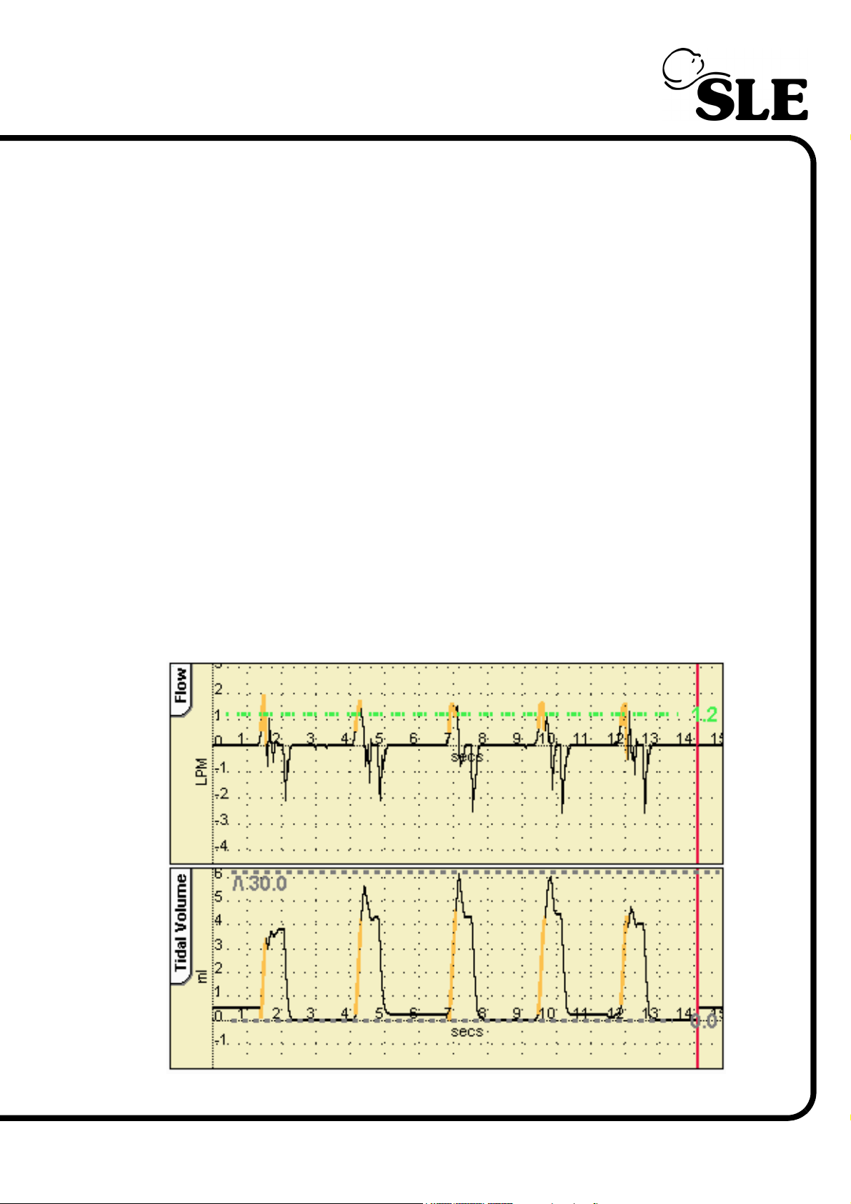
PTV Flow and Tidal volume waveforms.
Page 17 of 292
Page 18

Note: PTV will continue to function as stated, but with breath rates of 20 and
above apnoea alarms will be ignored by the ventilator. Breath rates of 20BPM
and above are deemed sufficient to support the patient. Should the breath
rate be set below 20BPM the apnoea alarm is enabled.
2.3.1 PTV with TTV (Targeted Tidal Volume)
This is as for basic PTV where the inspiratory phase shall be truncated when the set volume
has been delivered for mechanical back up breaths only.
The User sets the following:-
• Enables Targeted Tidal Volume (Tidal Vol) and selects volume to be delivered
•Max PIP
•Max Ti
Page 18 of 292
Page 19

2.4 PSV
Pressure Supported Ventilation
This is a pressure limited mode of ventilation in which each breath is patient triggered and
supported. The breath is patient triggered, pressure supported and patient terminated. The
infant therefore has control of the whole cycle, i.e. the inspiratory time, frequency and minute
volume. This form of ventilation is dependant on the use of a flow sensor placed between the
ET tube connector and the patient circuit. Changes in flow or volume signal detects
spontaneous breathing.
The termination sensitivity is also user adjustable from 0% - 50%. 5% termination sensitivity
means that 95% of the peak flow has been achieved. Pressure support can be manually
adjusted by use of the PIP parameter control.
Note: If the user sets the termination sensitivity to OFF the PSV mode
behaves as PTV.
PSV can be used in the weaning process. Weaning is achieved by reducing the support
level as the infant is able to make more effort.
In this mode all the patient's breath attempts are pressure supported, but mechanical
breaths are delivered at the set parameters (Ti, PEEP and PIP) when a patient effort is
recognised.
The User sets the following:-
• Positive End Expired Pressure (PEEP)
• Peak Inspiratory Pressure (PIP)
• Inspiratory Time (Ti)
• Backup breath rate (Backup)
• The flow termination sensitivity
• Apnoea Time (Only if backup breath rate is 19 breaths per minute or lower)
•Fi0
2
• Flow breath detection threshold (Set Trigger) - The patient effort required to satisfy
the apnoea alarm.
• High and low pressure alarm thresholds
• Tidal volume, high and low alarm thresholds
• Minute volume, high and low alarm thresholds
Page 19 of 292
Page 20
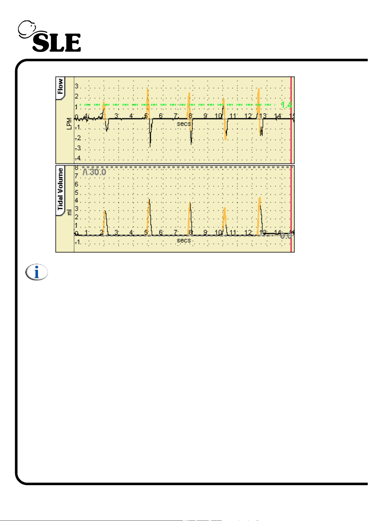
PSV Flow and Tidal volume waveforms (with termination sensitivity).
Note: PSV will continue to function as stated, but with breath rates of 20 and
above apnoea alarms will be ignored by the ventilator. Breath rates of 20BPM
and above are deemed sufficient to support the patient. Should the breath
rate be set below 20BPM the apnoea alarm is enabled.
2.4.1 PSV with TTV (Targeted Tidal Volume)
This is as for basic PSV where the inspiratory phase shall be truncated when the set volume
has been delivered, (for mechanical back up breaths).
The User sets the following:-
• Enables Targeted Tidal Volume and selects volume to be delivered
•Max PIP
•Max Ti
Page 20 of 292
Page 21
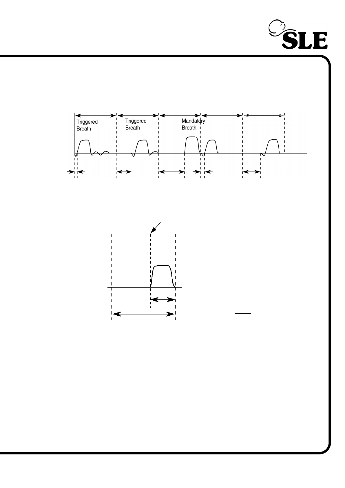
2.5 SIMV (Synchronized Intermittent Mandatory Ventilation)
The frequency of mandatory breaths is determined by the BPM control. When a mandatory
breath is due an assist window opens and waits for a patient's inspiratory effort. When this
occurs the ventilator delivers a synchronised breath (SIMV breaths). Once the breath has
been delivered the assist window closes until the next set breath is due.
Time windows
Assist windows
If the ventilator does not see a patient's attempt to breathe before the end of the defined time
window then a mandatory breath is delivered. The mandatory breath point is the Time
Window minus the Inspiratory Time.
Mandatory breath point
Inspiratory time
Time window =
60
BPM
User sets the following:-
•BPM
• Apnoea time (Only if backup breath rate is 19 breaths per minute or lower)
• Positive End Expired Pressure (PEEP)
• Peak Inspiratory Pressure (PIP)
• Inspiratory Time (Ti)
•Fi0
2
• Flow breath detection threshold (Set Trigger) - The patient effort required to satisfy
the apnoea alarm.
• High and low pressure alarm thresholds
• Tidal volume, high and low alarm thresholds
• Minute volume, high and low alarm thresholds
Page 21 of 292
Page 22
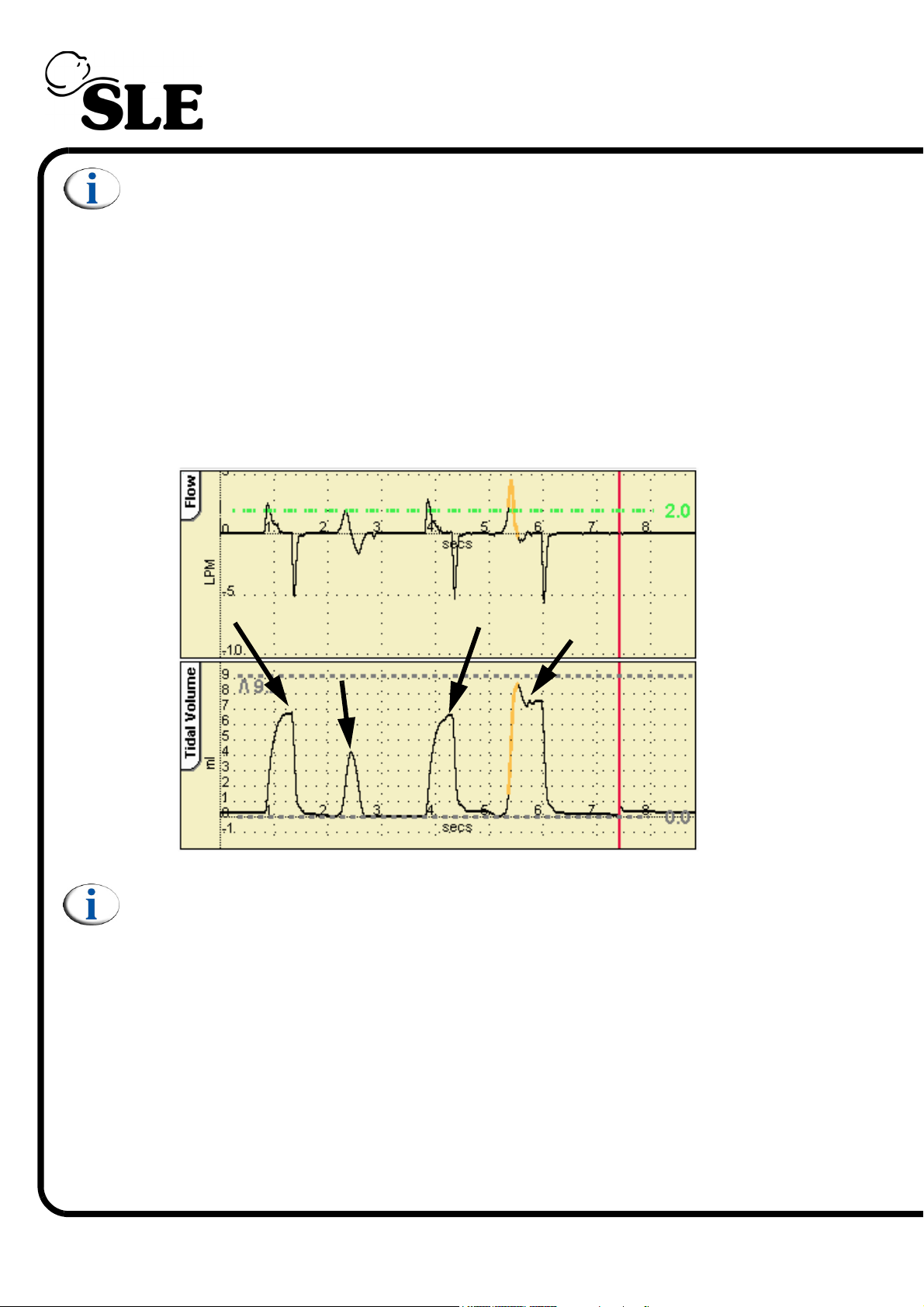
Note: SIMV will continue to function as stated, but with breath rates of 20 and
above apnoea alarms will be ignored by the ventilator. Breath rates of 20BPM
and above are deemed sufficient to support the patient. Should the breath
rate be set below 20BPM the apnoea alarm is enabled.
2.5.1 SIMV with PSV
SIMV with PSV allows the user to select the termination sensitivity and pressure support
level on non SIMV breaths. Once a mechanical breath is delivered to the patient, the flow to
the infant rapidly peaks and then decelerates to the termination threshold, inspiration ends
and expiration can begin.
The following parameters must be selected: PEEP, PIP, Ti, Breath detection level,
Termination sensitivity level, Backup BPM, Apnoea delay time, O2%.
SIMV breath
Un-supported
patient breath
SIMV breath
Supported triggered
breath
below trigger
threshold
Note: The ventilator does not apply termination sensitivity to SIMV breaths.
All patient triggered, pressure supported breaths are flow terminated unless
the user sets the stop support % value to OFF.
SIMV with PSV produces time cycled, pressure limited breaths that are delivered at a set
BPM rate. Any additional patient breath attempts are pressure supported (Flow cycled,
pressure limited).
User sets the following:-
• The flow termination sensitivity
• Percentage pressure support
Page 22 of 292
Page 23

2.5.2 SIMV with TTV (Targeted Tidal Volume)
This is as for basic SIMV with or without Pressure Support, where the inspiratory phase shall
be terminated if the set volume has been delivered.
The User sets the following:-
• Enables Targeted Tidal Volume and selects volume to be delivered
•Max PIP
•Max Ti
2.6 HFO (SLE5000 only)
High Frequency Oscillation
In this mode, the ventilator shall deliver continuous high frequency oscillation. There is no
patient interaction.
The User sets the following:-
•HFO rate
• Mean pressure
• Pressure amplitude (or Delta P)
•Fi0
2
• High and low alarm pressure thresholds
• Tidal volume, high and low alarm thresholds
• Minute volume high and low alarm thresholds
2.7 HFO+CMV (SLE5000 only)
A combination of oscillations during the expiratory or inspiratory & expiratory phase of a time
cycled, pressure limited breath in CMV mode.
The User sets the following:-
•BPM
• Inspiratory Time (Ti)
• Peak Inspiratory Pressure (PIP)
• Positive End Expired Pressure (PEEP)
•HFO rate
• HFO activity (oscillations in inspiratory and expiratory phases or expiratory phase
only)
• Pressure amplitude (Delta P)
•Fi0
2
• High and low alarm pressure thresholds
• Tidal volume, high and low alarm thresholds
• Minute volume high and low alarm thresholds
Page 23 of 292
Page 24

2.8 Mode controls
2.8.1 TTV Control Mode (Targeted Tidal Volume)
The aim of TTV is to prevent over distension of the alveoli and thereby limit volutrauma. By
targeting a selected tidal volume, and achieving and maintaining the tidal volume with
pressure ventilation, also limits barotrauma.
Targeted tidal volume can be applied to all modes of pressure cycled ventilation, provided
that a flow sensor is in situ. TTV cannot be applied in HFO or HFO+CMV.
Once an applicable mode has been selected, and the following parameters have been set
by the user i.e. PEEP, PIP, Ti, Rate and O2, the user may then choose to apply Targeted
Tidal Volume.
Once TTV has been activated and a target tidal volume selected the following occurs:
The PIP initially selected becomes the maximum PIP available (MAX PIP). To achieve the
targeted tidal volume only a percentage of the MAX PIP may be used. The MAX PIP is not
delivered to the patient unless the targeted volume is not being achieved. The Ti set
becomes the MAX Ti when TTV is applied. The time taken to achieve the targeted tidal
volume may be shorter than the MAX Ti. This is because the required volume is delivered
before the Ti is reached. The actual or measured Ti is displayed on the right hand side of the
screen and with in the eyebrow on the parameter setting. If the measured Ti is felt to be too
short, then the user may “slow down” the wave shape, using the wave shape button, to
prolong the breath to increase the measured Ti
Practical Considerations. The targeted tidal volume is delivered on a breath by breath basis.
This means that there is not a variable tidal volume in the initial phase of TTV.
However if the resistance of the lungs increases, the measured PIP will increase up to the
MAX PIP allowed, to achieve the targeted tidal volume. No more than the MAX PIP will be
delivered to the patient unless increased by the user.
Conversely, as compliance increases the measured PIP automatically decreases to
maintain the targeted volume. In effect weaning down the pressures as the lungs improve.
If volume cannot be achieved, the MAX Ti can be increased to allow for the delivery of the
targeted tidal volume. The breath then becomes time limiting as opposed to volume limiting.
Page 24 of 292
Page 25

2.9 Technical Description
The ventilator is a computer controlled ventilator. The computer is broken down into three
electronic subsystems that are housed in the upper (electronic) section of the ventilator.
The three sub systems are user interface, monitor and control.
The interface subsystem controls the user interface, the display and the touch screen. The
controller subsystem regulates the pneumatic systems of the ventilator. The monitor
subsystem collects and processes flow data and generates the alarms. Each subsystem
communicates with the other two in a peer to peer protocol, i.e. no subsystem is in complete
control.
The ventilator is fitted with an auto-ranging power supply that is capable of working with
mains supplies of 100v to 250v 50-60 Hertz. (Fuse ratings must change between the supply
voltages, 100v to 110v 2amp and 220 to 250v 1amp.)
The ventilator carries an onboard back up power supply, which consists of sealed lead/acid
batteries, that can power the ventilator in the event of a mains power fail. The batteries are
charged from the ventilators power supply. Both the battery supply and mains power supply
are monitored by the ventilators other subsystems. In normal modes of ventilation and with a
fully charged battery, in a mains power fail situation the ventilator will continue to operate for
45 minutes to 60 minutes depending on ventilation mode.
The pneumatic system consists of the following:
An electronic oxygen blender supplying blended gas to a mixing chamber. The blended gas
is then controlled via solenoid valves to supply the conventional ventilation system and the
oscillatory system.
For conventional ventilation the gas is then controlled by two pressure regulators that
produce positive and negative gas flows via the forward and reverse jets.
For oscillatory ventilation the gas flow is controlled by four in-line high speed solenoid valves
that produce the oscillatory gas flow via the forward and reverse jets.
The exhalation block mounts onto two jet ports one forward/reverse and one mean pressure.
Pressure is monitored via the proximal airway port through a pair of pressure transducers
with data being sent to the monitor subsystem.
Flow is monitored by a dual hot wire anemometer mounted at the ET manifold with the flow
data being sent to the monitor subsystem.
Page 25 of 292
Page 26

3. User/Owner Responsibility
The ventilator and the authorised accessories for it are designed to be used in accordance
with supplied manuals and instructions. This equipment must be periodically checked,
recalibrated, maintained and components repaired and replaced when necessary for the
equipment to operate safely and reliably.
Parts that have failed, in whole or in part, or exhibit excessive wear, or are contaminated, or
are otherwise at the end of their useful life, should not be used and must be replaced
immediately with parts supplied by SLE, or parts which are otherwise approved by SLE.
Equipment which is not functioning correctly or is otherwise in need of repair or maintenance
must not be used until all necessary repairs and/or maintenance have been completed and a
factory authorised service representative has certified that the equipment is fit and ready for
use. This equipment, its accessories or component parts should not be modified. The use of
non-approved parts or accessories will invalidate the warranty.
The owner/user of this equipment shall have the sole responsibility and liability for any
damage or injury to persons or property (including the equipment itself) resulting from
operation not in accordance with the operating instructions, or from faulty maintenance not
in accordance with the authorised maintenance instructions, or from repair by anyone other
than the factory authorised service representative, or from unauthorised modification of the
equipment or accessories, or from the use of components or accessories that have been
either damaged or not authorised for use with this equipment by the manufacturer.
Page 26 of 292
Page 27

Operational and Clinical Warnings
Page 27 of 292
Page 28

4. Warnings
4.1 Operational Warnings
The following warnings must be read and understood before using the ventilator. Failure to
do so could lead to injury or death of the patient.
General
1. The whole of this manual should be read and understood before using the ventilator.
Operators must be suitably trained and clinically authorized for using the ventilator with
patients. Particular care should be taken to check the ventilator pressures prior to
changing modes.
2. Oxygen - Clinical use. Oxygen is a drug and should be prescribed as such.
3. Oxygen - Fire Hazard. Oxygen vigorously supports combustion and its use requires
special precaution to avoid fire hazards. Keep all sources of ignition away when oxygen
is in use. Do not use oil or grease on oxygen fittings or where oxygen is used.
4. Check the condition of the gas supply hoses to the ventilator. Do not use any hose that
shows signs of cracking, abrasion, kinking, splits, excessive wear or ageing. Make sure
that the Air or O2 hose has not come into contact with oil or grease.
5. Audible and Visual warning alarms indicate a potentially harmful condition to the patient.
6. When the ventilator is being used on a patient, a suitably trained person must be in
attendance at all times to take prompt action should an alarm or other indication of a
problem occur.
7. Never enter the “Ventilation Off” mode when connected to a patient.
8. An alternative form of ventilation should be available whenever the ventilator is in use.
(EN 794-1:1997)
9. Please read the operational notes, for information relating to ventilation options and
operational practice when the ventilator is connected to a patient.
10. Do not touch the patient and ventilator metalwork at the same time to avoid earthing the
patient.
11. The ventilator contains temperature dependant devices which perform normally in
controlled environments in hospitals. However if the ventilator has been stored at a
temperature different to that in which it will be used, allow the unit to acclimatize before
powering up. (See “Operating Environment”: on page 272.)
12. Any computer connected to the ventilator must be specified for medical use (i.e. it must
comply with the requirements of BS-EN-60601:1990).
Page 28 of 292
Page 29

Ventilator
13. Do not use a sharp instrument, such as a pen to activate the controls as the excessive
pressure applied by the point will damage the touch screen membrane.
14. When the ventilator is used without the flow sensor and ventilating a patient with a 3mm
or smaller size endotracheal tubes, in the case of patient extubation or the ET tube
disconnecting from its ET connector, only the monitoring of flow, or of SpO2, or of
transcutaneous Oxygen and Carbon Dioxide will dependably alert the medical team to
an alarm situation, not the monitoring of pressures.
15. The ventilator functional tests must be carried out each time the ventilator is used on a
patient. If any of these tests do not function as described then there is a problem and the
ventilator must not be used until it is rectified.
16. Failure to comply with the recommended service programs could lead to injury of the
patient, operator or damage to the ventilator. It is the owners responsibility to ensure that
the equipment is regularly maintained.
17. The Ventilator must be connected to a suitably rated and grounded electrical power
source.
18. The ventilator can operate on battery power in the event of mains power failure for a
maximum of 45-60 minutes (If battery fully charged at start of mains power failure).
Whilst on battery power an alternative form of ventilation should be made ready if the
mains power supply cannot be restored.
19. If the ventilator is adversely affected by equipment emitting electromagnetic interference
then that equipment should be switched off or removed from the vicinity of the SLE5000.
Conversely, if the ventilator is the source of interference to other neighbouring
equipment, it should be switched off or taken to another location.
20. The functioning of this machine may be adversely affected by the operation of
equipment such as high frequency surgical (diathermy) equipment, defibrillators, mobile
phones or short-wave therapy equipment in the vicinity.
21. The equipment is not suitable for use with, or in the presence of flammable anaesthetic
mixtures.
22. The ventilator flow monitoring system is calibrated to work in an air / oxygen mixture, the
use of other gas mixtures may affect the flow monitoring accuracy of the ventilator.
23. Do not clean the touch screen whilst the ventilator is in operation.
24. Disposal of the Oxygen cell should be in accordance with local regulations for
hazardous substances. Do not incinerate. SLE offer a cell disposal service.
Page 29 of 292
Page 30

25. The ventilator contains six batteries, three sealed lead acid batteries, two alkaline and
one PCB mounted lithium battery. At the end of their useful life these batteries should be
disposed of in accordance with local authority guidelines.
26. Apart from the batteries, the ventilator and accessories do not contain any hazardous
components therefore no special precautions are required for their disposal. The
ventilator should be disposed of in accordance to the local WEEE (Waste Electrical and
Electronic Equipment) guidelines.
27. Care should be taken when attaching other equipment as this may affect mechanical
stability.
28. There is no special protection provided against ingress of water or liquids.
29. When using the ventilator with Nitric Oxide therapy devices, two N4110 filters are
required to scavenge all the waste Nitric Oxide. See “Nitric Oxide Therapy” on
page 146.
30. In the event of main LCD screen failure remove the patient as soon as possible (under
clinical supervision) from the ventilator to an alternative form of ventilation. The
ventilator will continue to ventilate on the set parameters whilst this is arranged.
31. Do not use solvent based cleaning solutions to clean the touch screen or covers.
Humidifier / Patient Circuit
32. Use only SLE approved patient circuits. On no account should antistatic or electrically
conductive tubing be used.
33. The humidifier used in the patient circuit must be operated and maintained in
accordance with its manufacturer’s instructions.
34. Any water trap used in the patient circuit must be held in the upright positions and
drained regularly before it is full.
35. The patient circuit should not be modified. Modified patient circuits or circuits with
additional sections or components may produce too high a circuit resistance and circuit
compliance for effective ventilation.
36. The use of bacterial filters between the fresh gas port and humidifier supply line &
exhalation block and the expiratory supply line is strongly recommended.
Page 30 of 292
Page 31

Flow Sensor
37. The presence of secretion on the sensor mesh may cause increased resistance. Set
alarms closely to detect clinically significant changes.
38. When carrying out ET suctioning with the ventilator delivering high flow rates it is
possible to activate the sensor contamination alarm inadvertently. To avoid this situation
disconnect the ET manifold first from the flow sensor, then the flow sensor from the ET
tube. It is also important to reconnect the flow sensor and manifold in the reverse order
so as to again avoid the contamination alarm. For more information please refer to
“Circuit Disconnection Procedure” on page 138.
39. A new flow sensor is delivered clean, but not sterile. It should be autoclaved as
described in the Cleaning and Disinfection Procedures prior to initial use. Use only SLE
approved flow sensors (Part number: N5201).
40. Because a patient’s inspired gas comes into contact with the internal parts of the flow
sensor that can absorb disinfecting agents, be sure to disinfect the sensor according the
techniques described in “Cleaning and Sterilization” on page 184.
41. Repeated autoclave cycles may cause surface crazing which may only be cosmetic and
not affect performance or safety. Inspect the sensor for integrity following disinfection
and before each use. Discard and replace if significant structural cracking is noted.
4.2 Clinical Warnings
Failure to take corrective action when the alarms are activated could result in injury or death
to the patient.
There are risks inherent in the use of both conventional and high-frequency forms of
mechanical ventilation in the neonatal and paediatric patient. These may include:
1. Under- or over-ventilation (with consequent abnormalities in blood gases);
2. Incorrect humidification; could cause mobilisation of secretions and airway blockage.
3. Intracranial haemorrhage, cerebral ischaemia;
4. Chronic lung disease (bronchopulmonary dysplasia in the newborn);
5. Damage to trachea and bronchi;
6. Over- or under- inflation of the lung;
7. Atalectasis;
8. Air leak syndrome (pneumothorax, pneumomediastinum, pneumopericardium.
pulmonary interstitial emphysema);
Page 31 of 292
Page 32

9. Circulatory abnormalities (reduced systemic or pulmonary venous return, hypotension,
tachycardia, bradycardia, reduced cardiac output, excessive variability of blood
pressure);
Maintenance of an adequate airway is paramount in the infant or child undergoing highfrequency oscillatory ventilation. The following points should be stressed in airway
management on units employing HFOV:
10. The largest endotracheal tube should be used which is compatible to that patient;
11. Chest wall “bounce” (vibrations of chest wall caused by HFOV) should be verified
regularly as part of nursing care;
12. Transcutaneous carbon dioxide measurement or frequent arterial blood gas samples
must be employed to alert the users to any change in patient condition.
The minimum patient monitoring requirements for HFOV are:
13. ECG/heart rate.
14. Chest wall movement.
15. Blood pressure (either by invasive or non invasive means).
16. Oxygen saturation.
17. Transcutaneous carbon dioxide arterial / capillary blood sampling.
18. Regular chest X-rays to verify efficiency of HFOV.
19. Regular cranial ultrasound examinations (in the newborn).
20. Standard nursing care for Intensive Care patients.
21. Special care should be taken when ventilating using HFOV during the administration of
natural surfactant to avoid "foaming" of surfactant in the lung and subsequent
deterioration.
22. When switching from conventional to high-frequency ventilation, or vice-versa,
alterations in ventilator settings and inspired oxygen concentrations may be required.
23. Exposing a baby to elevated concentrations of oxygen may lead to Retrolental
Fibroplasia (retinopathy of prematurity).
24. HFOV should only be instituted by fully trained and experienced medical personnel.
Page 32 of 292
Page 33

Ventilator Description
Page 33 of 292
Page 34
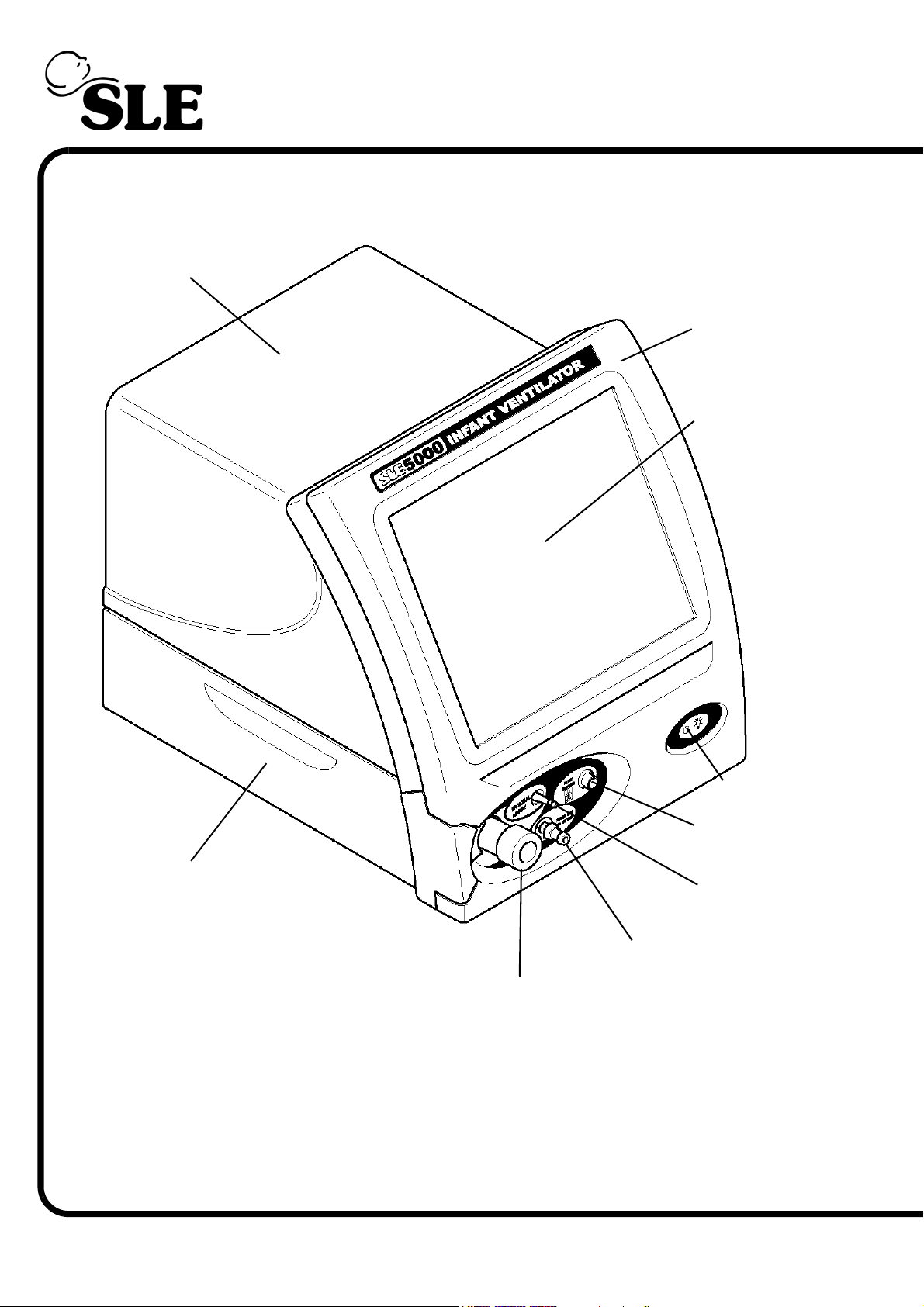
Rear Cover
5. Ventilator Description
Front cover
Touch Screen
Exhalation Block Flap
Power On
LED
Flow Sensor
Connector
Proximal Airway Port
Fresh Gas Port
Exhalation Block
Front View
Page 34 of 292
Page 35
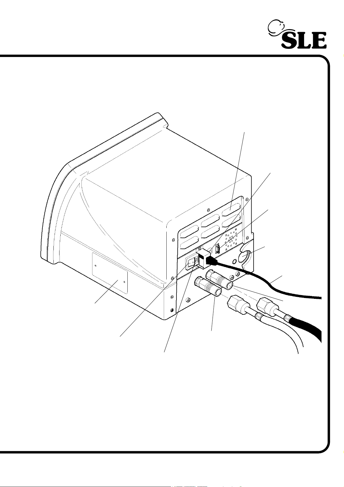
Cooling louvres
Battery Power
Termi nato n
Switch
RS232
& Viewlink
Connector
Exhaust port
for Exhalation
Block
Mains Power
Cable
O2 Cell cover
Mains Power Switch
Air Supply
Inlet
Oxygen Supply
Inlet
Fuse Holder
Rear View
Page 35 of 292
Page 36
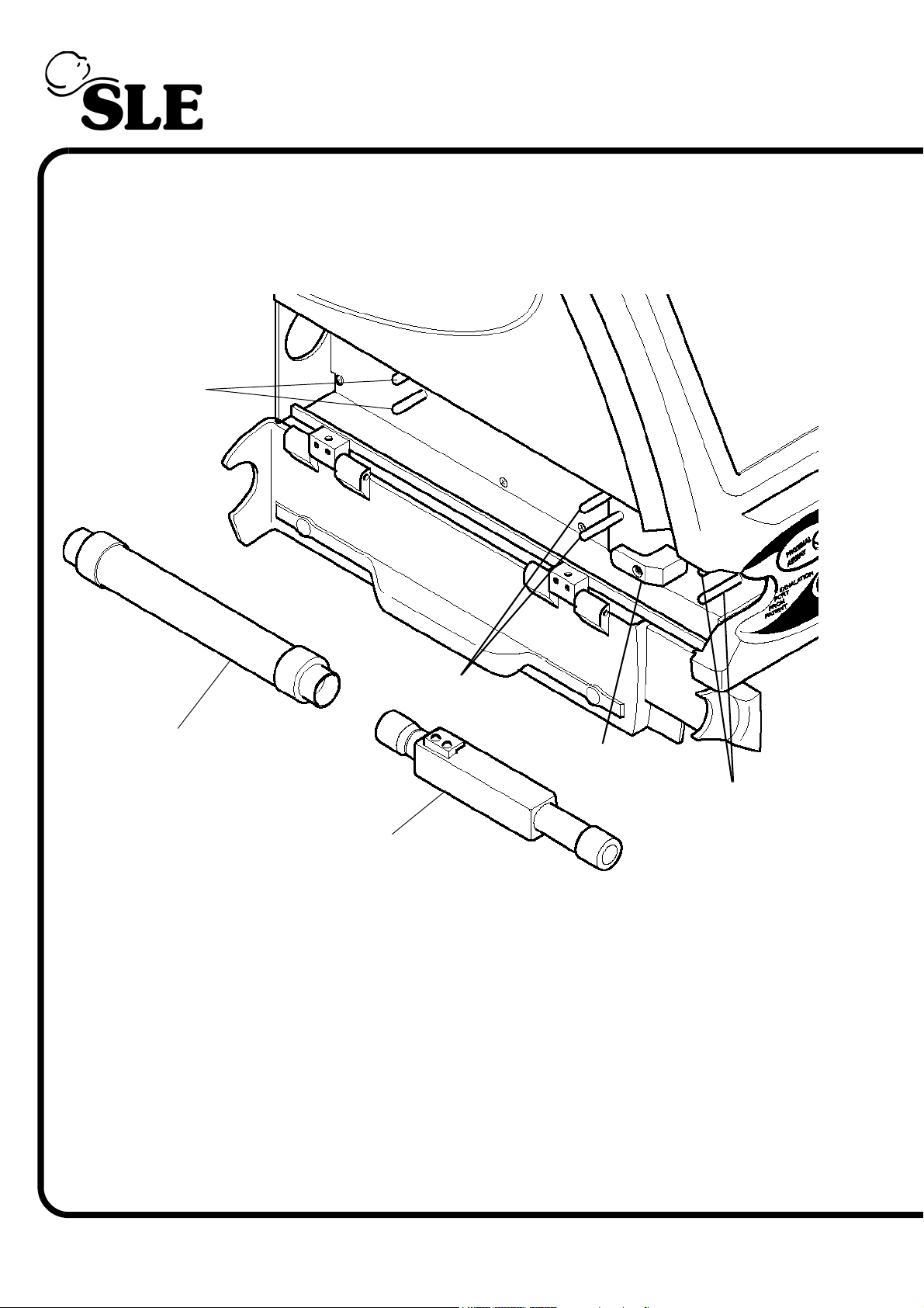
Silencer Guides
Exhalation Block
Guides
Silencer
Exhalation Block
Clamp
Exhalation Block
Guides
Exhalation Block
Exhalation Block Port
Page 36 of 292
Page 37
6. Description of Symbols and Buttons
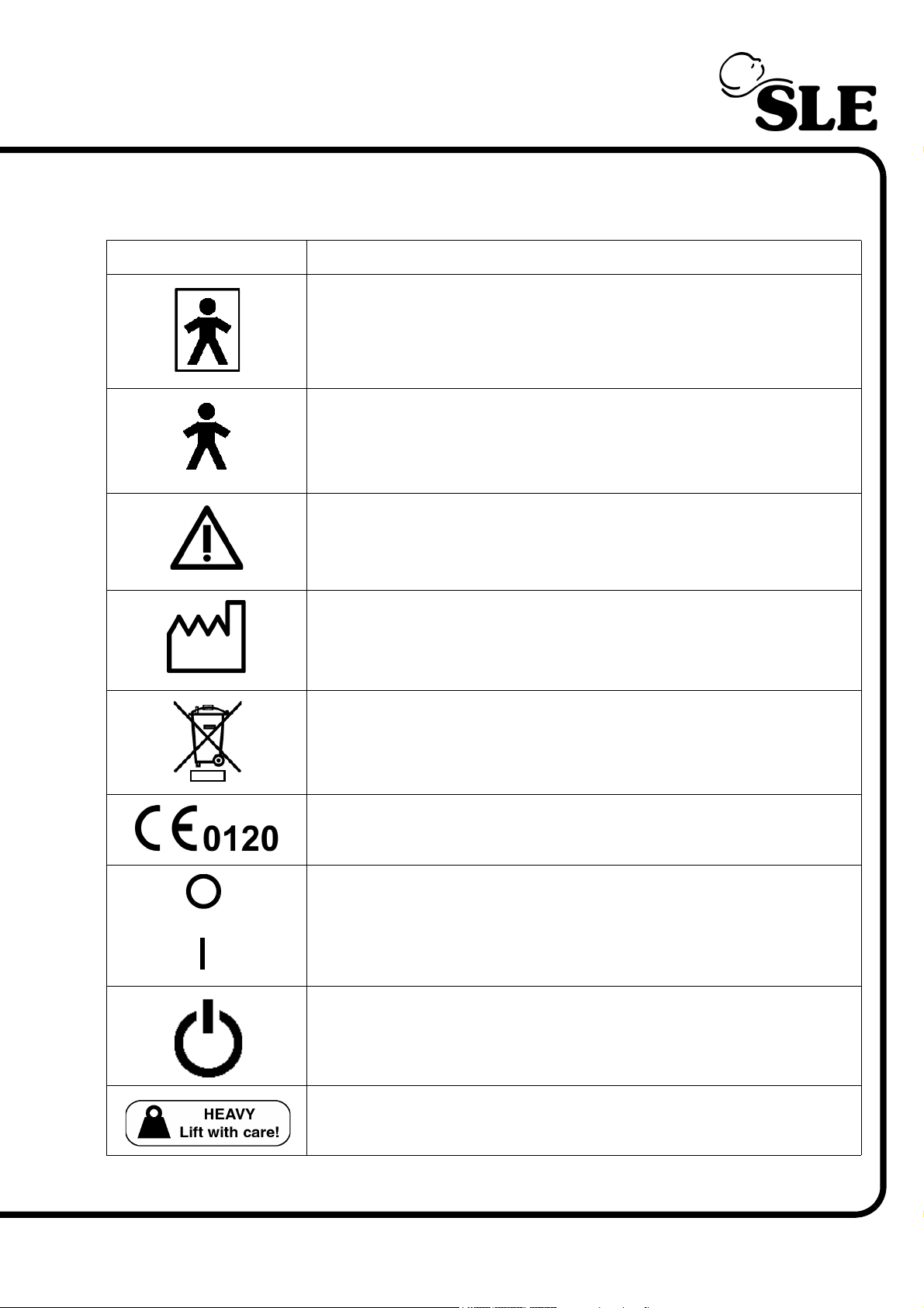
Symbol Description
Type BF connection (Situated on front panel).
Type B device (Situated on rear panel).
Read manual (Situated on rear panel).
Date of Manufacture (Appears on serial number label).
Do not dispose of as general waste (WEEE directive).
(Appears on serial number label).
EEC conformity marking showing compliance with the Medical
Devices Directive (Appears on serial number label).
Power Off
(Embossed on power switch)
Power ON
Indicates the mains power switch.
Heavy, Lift with care (Situated on rear panel).
Page 37 of 292
Page 38
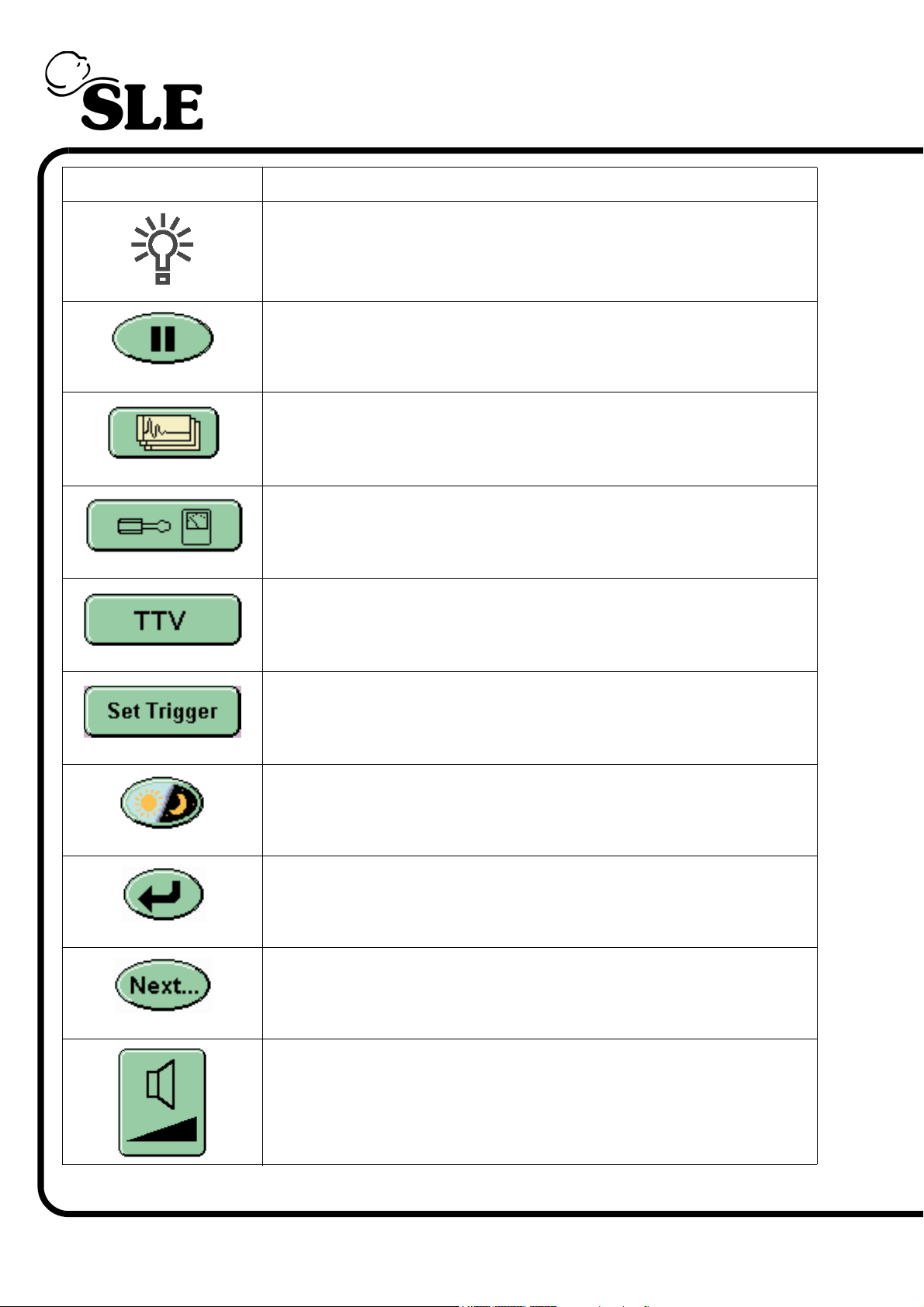
Symbol Description
Mains/Battery power indicator (Situated on front panel).
Screen pause.
Waveform display options.
Display options and service data.
Enables the Targated Tidal Volume Panel.
Enables the breath detection threshold in the flow window.
Night mode and Screen Lock.
Return button. Returns the user to previous panel.
Next Button. Advances user to the next panel.
Volume controls.
Page 38 of 292
Page 39
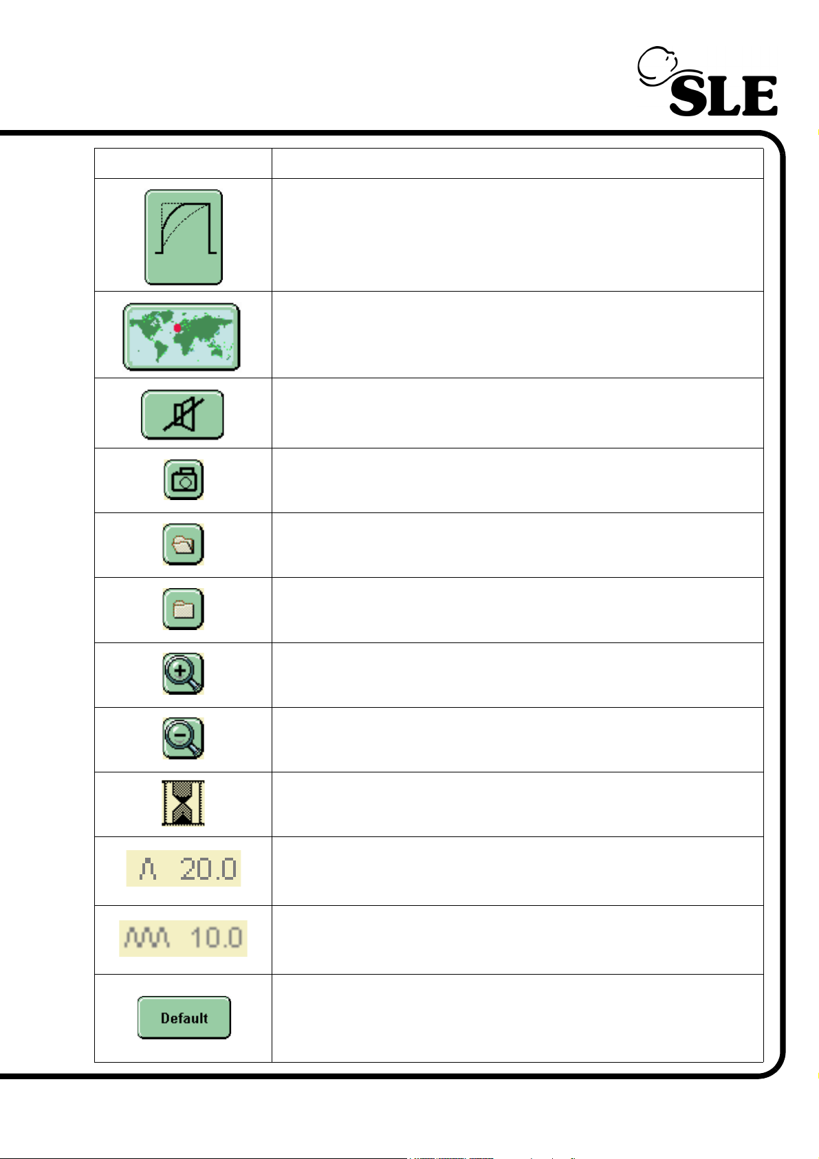
Symbol Description
Wave shaping controls.
Language selection.
Alarm mute.
Picture capture button.
Stored Loop (Loop on display).
Stored Loop (Loop in memory).
Zoom in.
Zoom out.
Please wait symbol. (Displayed when storing loop).
High Tidal Volume Alarm in mbar
Cycle Fail Alarm in mbar.
Returns the waveform windows to their default settings of:
Pressure, Flow and Tidal volume.
Page 39 of 292
Page 40
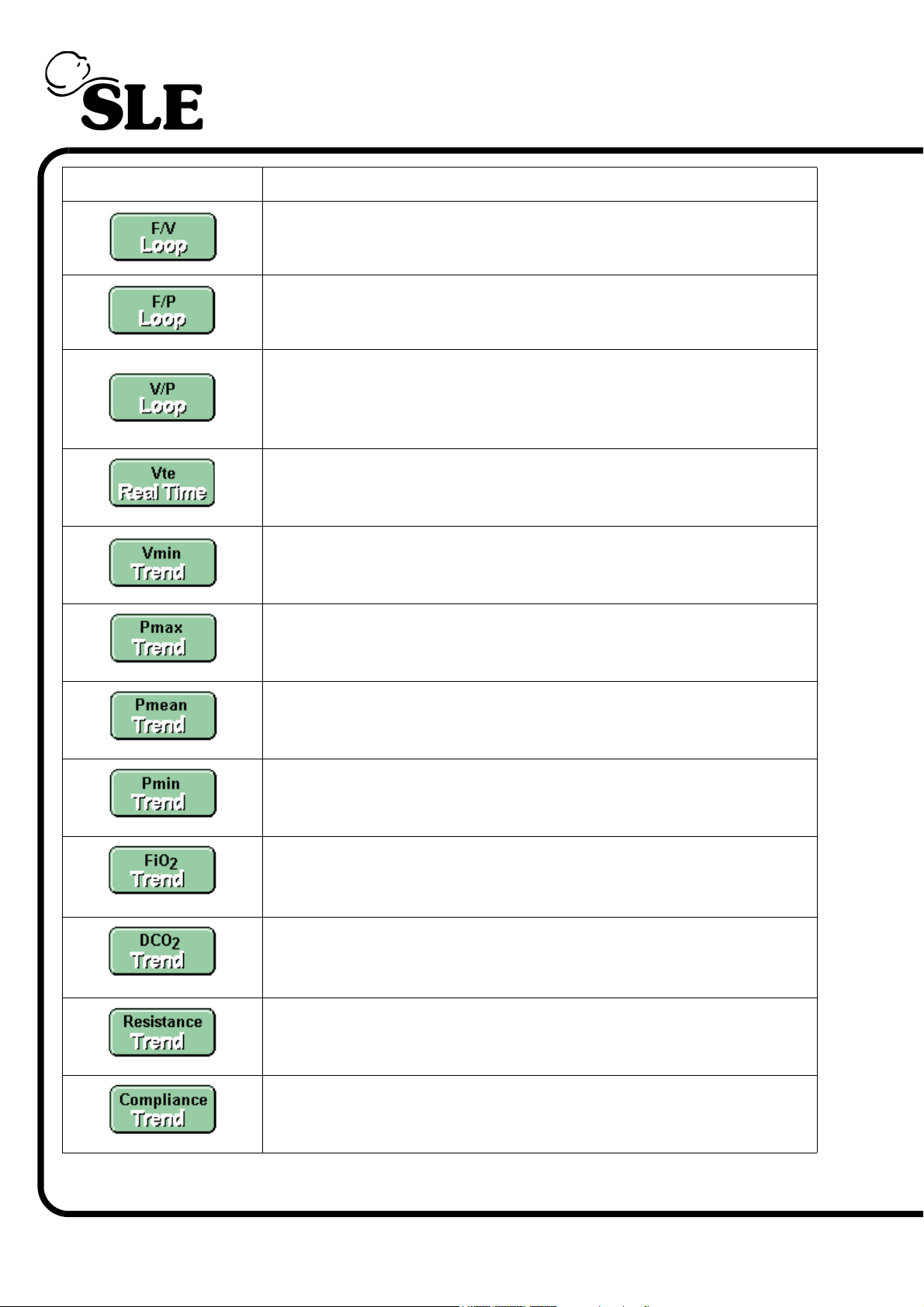
Symbol Description
Pressure wave window with Flow versus Volume loop display.
Pressure wave window with Flow versus Pressure loop display.
Pressure wave window with Volume versus Pressure loop
display.
Pressure wave window and Tidal Volume wave window.
Pressure wave window and Minute Volume wave window.
Pressure wave window and Max pressure against time display.
Pressure wave window and Mean pressure against time display.
Pressure wave window and Min pressure against time display.
Pressure wave window and FiO2 against time display.
Pressure wave window and DCO2 against time display.
Pressure wave window and Resistance against time display.
Page 40 of 292
Pressure wave window and Compliance against time display.
Page 41
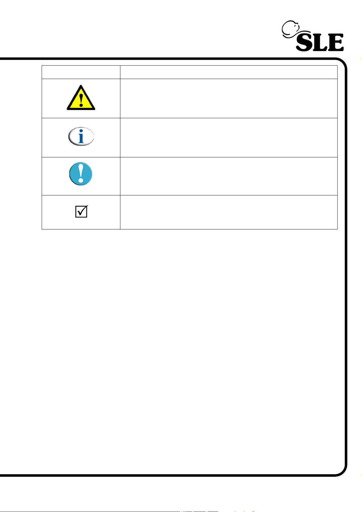
Symbol Description
Indicates a warning in the manual.
Indicates a note in the manual.
Indicates a caution in the manual.
Check list item.
A table explaining all abbreviations within this manual can be found on page 284.
Page 41 of 292
Page 42

This page is intentionally blank.
Page 42 of 292
Page 43

User Interface Description
Page 43 of 292
Page 44
7. User Interface
Warning: Do not use a sharp instrument, such as a pen to activate the touch
screen controls as the excessive pressure applied by the point will damage
the touch screen membrane.
Note: The ventilator touch screen works on a one touch principle. If the
user touches the screen at two points, the first point touched is recognized
and the second is ignored. Resting a finger on the screen will be registered
as the first touch, thus blocking all further operations.
The ventilator is controlled via the touch screen (user interface). All the controls
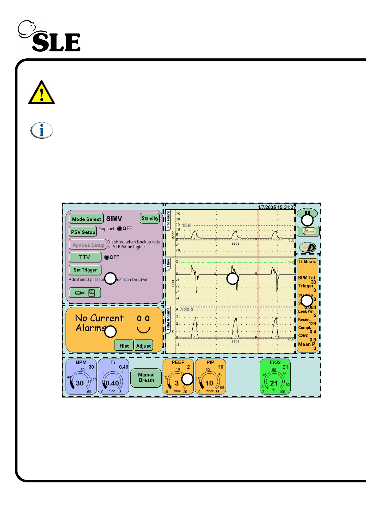
are accessible through the user interface. The interface is divided into sections.
Each section groups related controls or displays. The diagram below shows a
typical screen with the groups marked by dotted lines.
6
1
2
7.1 User Interface Sections
1. Mode panel
2. Alarm panel
3. Ventilation Parameters panel area
4. Waveform windows
5. Lung mechanics and measurement panel
6. Display options
4
5
3
Page 44 of 292
Page 45
The touch screen as the name suggests is controlled by touch. When using the
ventilator it is advisable to have clean dry hands (gloved hands will also activate
controls). Only a small amount of pressure is required to activate a control.
7.2 Description of User Interface Indicators
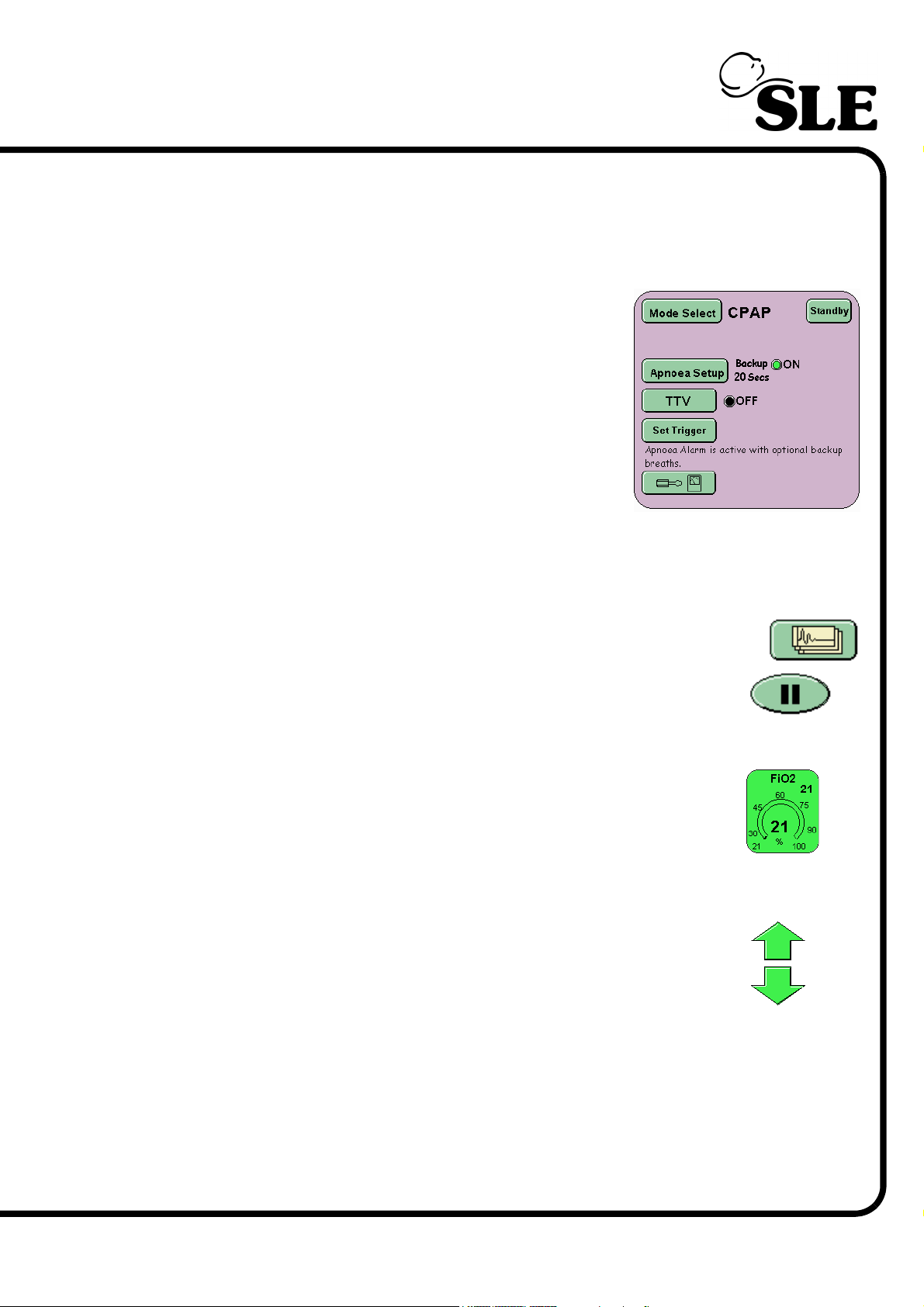
In the mode panel the user will find indicator lights
next to functions that can be turned ON or OFF.
When a function is OFF the light is coloured Black
and the text OFF is displayed.
When that function is ON the light is coloured Green
and the text ON is displayed
7.3 Description of User Interface Controls
The interface has three types of control: Button, Parameter and Arrow.
The buttons are coloured green, change shade when touched,
but vary in shape. The buttons are used to select a function or
mode.
The parameter controls vary in colour but are all the same shape.
A selected parameter will change to black when selected. The
parameter control selects a ventilator setting for modification. In
the center of the control is the measured value and in the top right
is the set value.
The up/down arrows allow modification of a selected control.
There are three colours of arrows ‘Orange’ for parameter
modification, ‘Red’ for alarm threshold modification and ’Green’
for FiO2 modification.
Page 45 of 292
Page 46
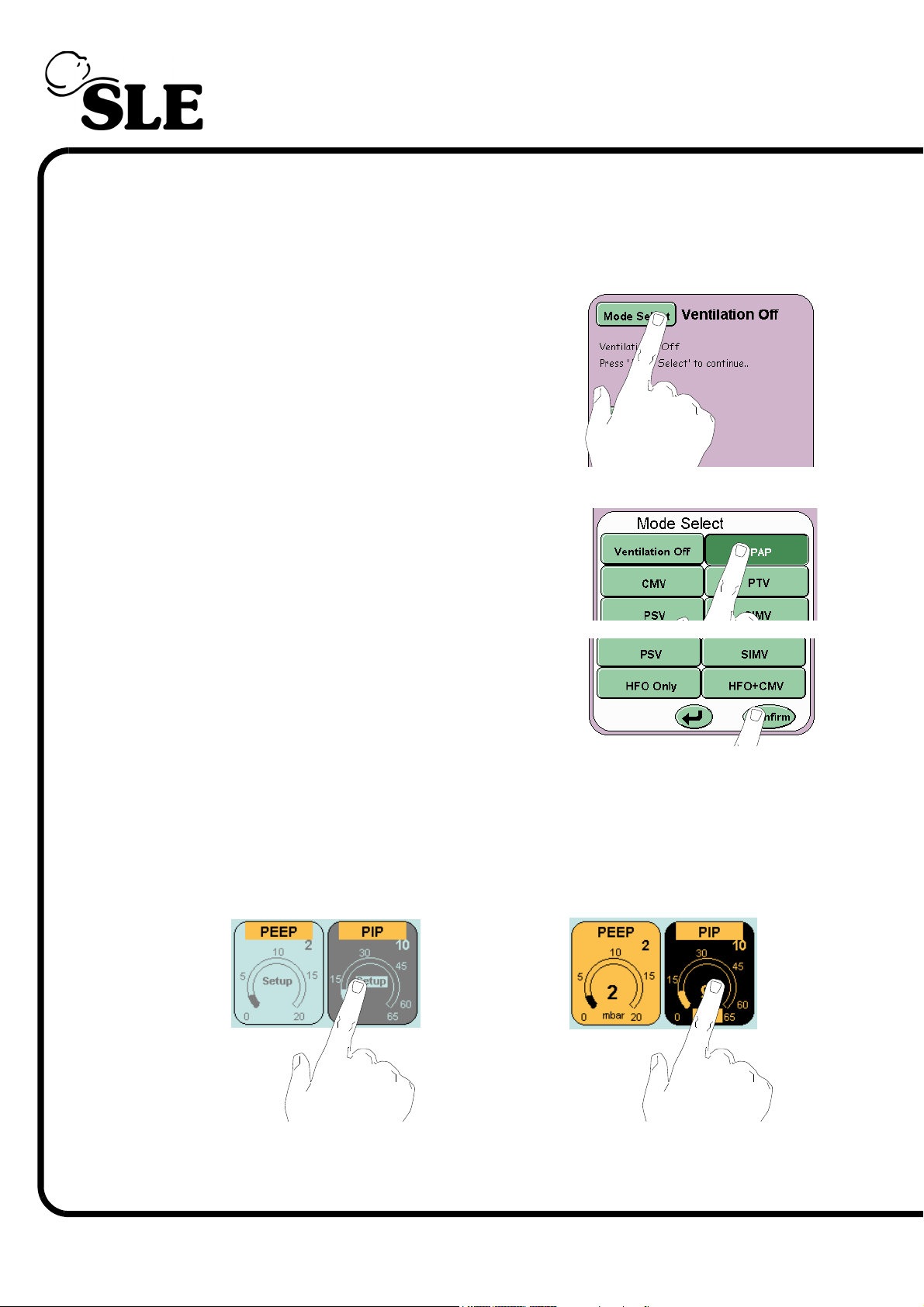
7.3.1 Examples of Control Use
The following section describes the use of each of the above controls.
7.3.1.1 Buttons
Touch the mode select button and this will activate
the mode select panel.
Select the required mode. The mode selected will be
highlighted by a colour change (from light green to
dark green).
Touch the confirm button this will activate the chosen
mode. If the user does not press the confirm button
the ventilator returns to the current mode after 20
seconds.
7.3.1.2 Parameter
The parameter controls can be selected in two ways. First in the preview stage
before entering a mode (Example A), the parameters do not display the
measured value and are blue. The second when in a selected mode (Example B),
the measured value is displayed and the parameter control is coloured (Orange
or Green).
Page 46 of 292
Example A
Example B
For example A the selected parameter changes colour to grey and for example B
the colour changes to black.
Page 47
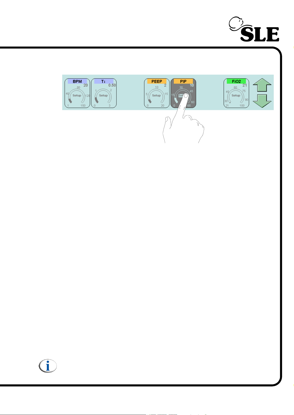
7.3.1.3 Up / Down Arrows
The arrows appear when a function or parameter which can be modified is
selected.
The up arrow increases the chosen value and the down arrow decreases the
value. The arrow selected changes colour when touched.
The arrow can be touched repeatedly to increment the parameter in individual
increments or held down to rapidly change the value. Holding down to rapidly
change the value is limited to steps of 10 increments.
User will have to release and repress the arrow to continue the next rapid
increase of 10 increments. This feature is to prevent any parameter being set to
maximum in one action.
7.3.1.4 Ti (Inspiratory Time) Parameter control
The Ti parameter control functions as described above but increments by 0.01
seconds.
7.3.1.5 Tidal Volume (TTV) Parameter Control
The tidal volume parameter control functions as described but has 3 resolutions.
From 2ml to 6ml the parameter increments in 0.2ml steps (Fine resolution).
From 6ml to 100ml the parameter increments in 1ml steps (Standard resolution).
From 100ml to 200ml the parameter increments in 5ml steps (Coarse resolution).
7.3.1.6 FiO
Parameter Control
2
The FiO
parameter control is the only parameter that does not function as
2
described above. The FiO2 parameter control allows for rapid setting to 100% O2.
The user can increase the percentage of O2 from the set percentage to 100% by
activating the FiO2 parameter and holding down the up arrow. (The control is not
limited to steps of 10 increments).
To decrease the percentage of O2 the parameter is limited to steps of 10
increments.
Note: If the up arrow is held down for a total of 8 seconds, the ventilator will
reset the percentage of O2 to the original setting. This is a safety feature in
case the touch screen develops a fault.
Page 47 of 292
Page 48
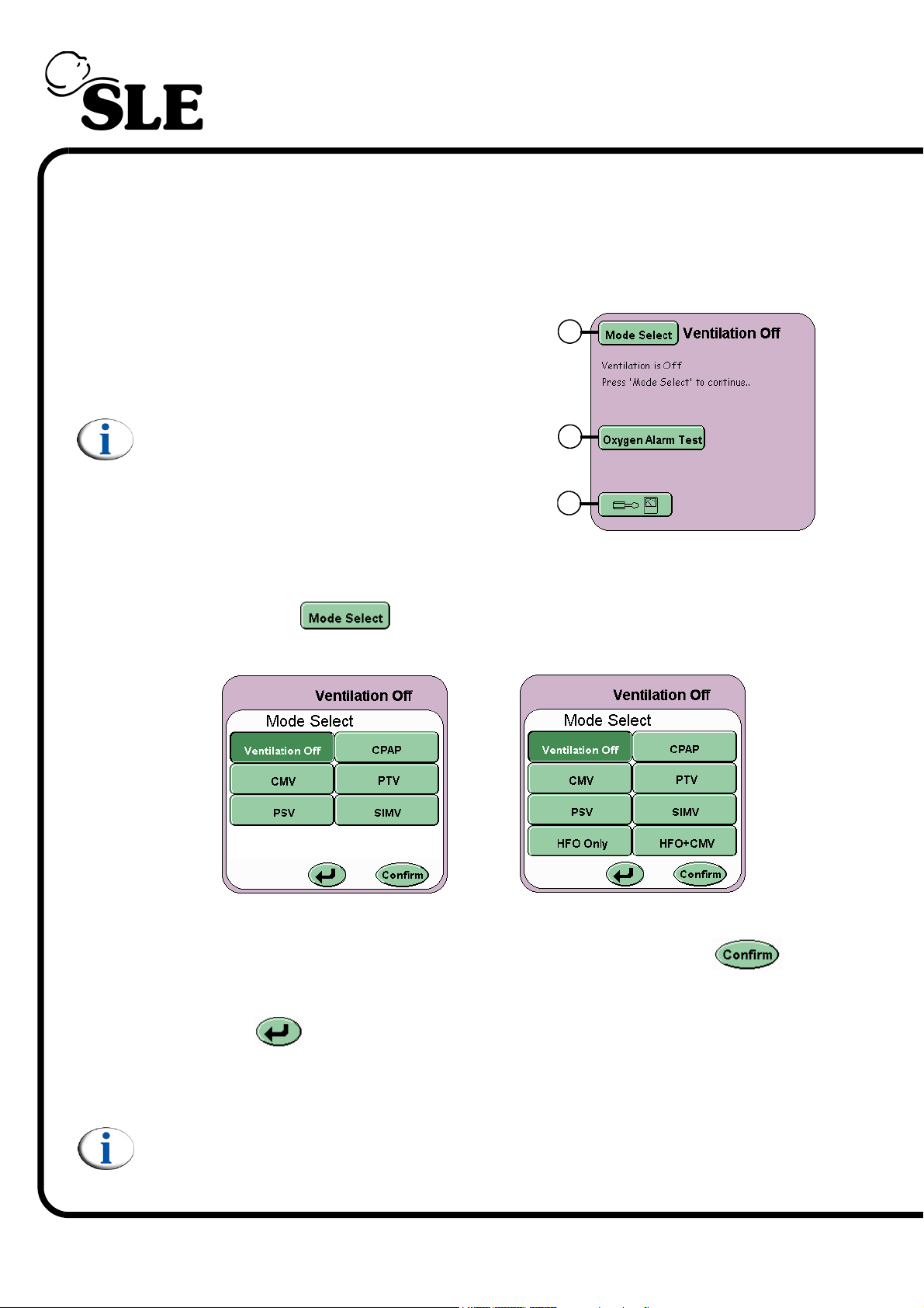
7.4 Description of the Mode Panel in Ventilation Off Mode
The Mode panel functions vary between modes of ventilation and Ventilation off.
7.4.1 Mode Panel in Ventilation Off Mode
The Mode Panel displays the Mode Select
button (A), the Oxygen Alarm Test button (B)
and the Options and Service Data button (C).
Note: In Ventilation Off mode alarm sounds
are muted to the minimum setting (1).
7.4.2 Mode Select Button
The Mode Select button activates the Mode Select Panel. The panel
displays all the ventilation modes that can be selected.
A
B
C
Page 48 of 292
SLE4000
SLE5000
Selection of the mode has to be confirmed by pressing the Confirm
button. (Note the confirm button flashes between green and white).
The Return button returns the user to the current mode and cancels any
parameter changes made in the preview mode.
Note: When changing between modes, for any alarms that have been
triggered the alarm sounder volume is set to its minimum setting, for a
period of 10 seconds. After the 10 seconds has expired the volume will
return to the user set value.
Page 49
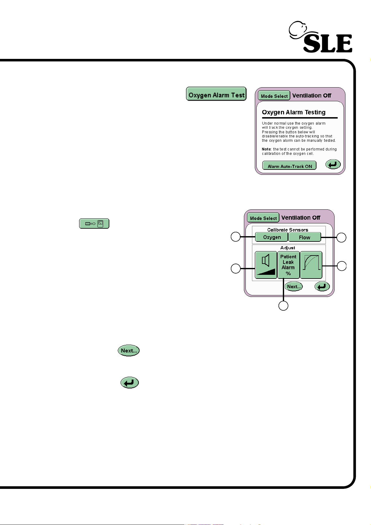
7.4.3 Oxygen Alarm Test
The Oxygen Alarm Test button
activates the Oxygen Alarm Testing panel.
This panel allows the user to test the High and Low
Oxygen alarm prior to use.
For a detailed description on how this test is carried
out, See “Oxygen Alarm Test” on page 98.
7.5 Services Panel
The Options and Service Data button
on the Mode Panel activates the
Services panel.
E
D
Displayed on this panel are five buttons:
In the Calibrate Sensors area
G
Flow (D)
Oxygen (E)
In the Adjust area
H
Wave shaping (F)
Volume control (G)
Patient leak alarm (H)
The Next... button advances the user to the More Options panel (See
“More Options Panel” on page 51.).
The Return button returns the user to the Ventilation Off panel.
F
Page 49 of 292
Page 50
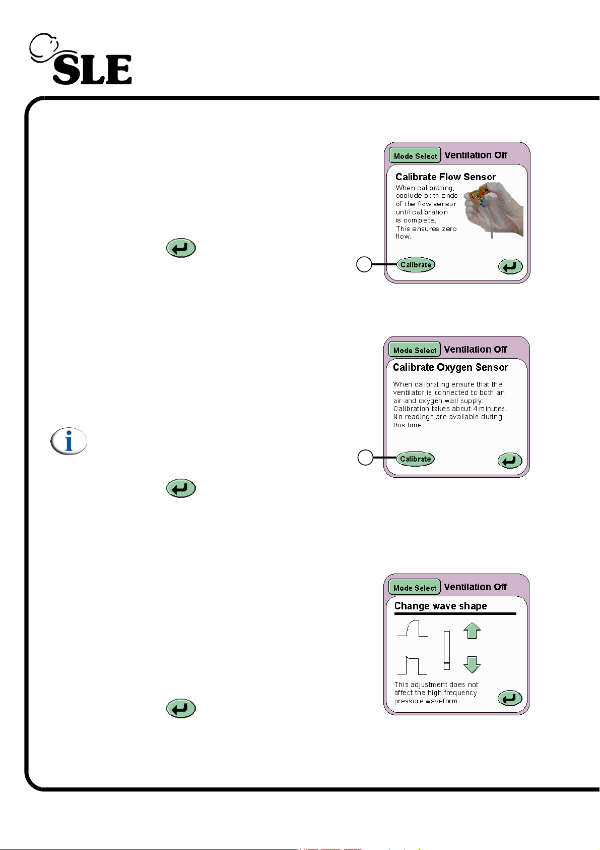
7.5.1 Flow
On pressing the Flow button (D) the Calibrate
Flow Sensor panel will be displayed. The
Calibrate button (I) runs the calibration routine
for the flow sensor. For more details on the
Flow Sensor and calibration see page 182.
The Return button returns the user to
the Services panel.
7.5.2 Oxygen
On pressing the Oxygen button (E) the
Calibrate Oxygen Sensor panel will be
displayed. The Calibrate button (J) runs the
one point calibration routine (100% O2) for the
Oxygen monitoring system.
I
Note: See section 21. on page 214 for
information on the two point oxygen sensor
calibration.
The Return button returns the user to
the Services panel.
7.5.3 Wave Shaping
On pressing the Wave shaping button (F) the
Change Wave Shape panel will be displayed.
The panel allows the user to modify the pressure
wave to produce a square or tapered wave shape.
Using the arrows the wave shape is modified in
realtime in the pressure waveform window.
The Return button returns the user to the
Services panel.
J
Page 50 of 292
For more information See “Wave Shaping” on page 137. of the “Operational
Considerations” chapter.
Page 51
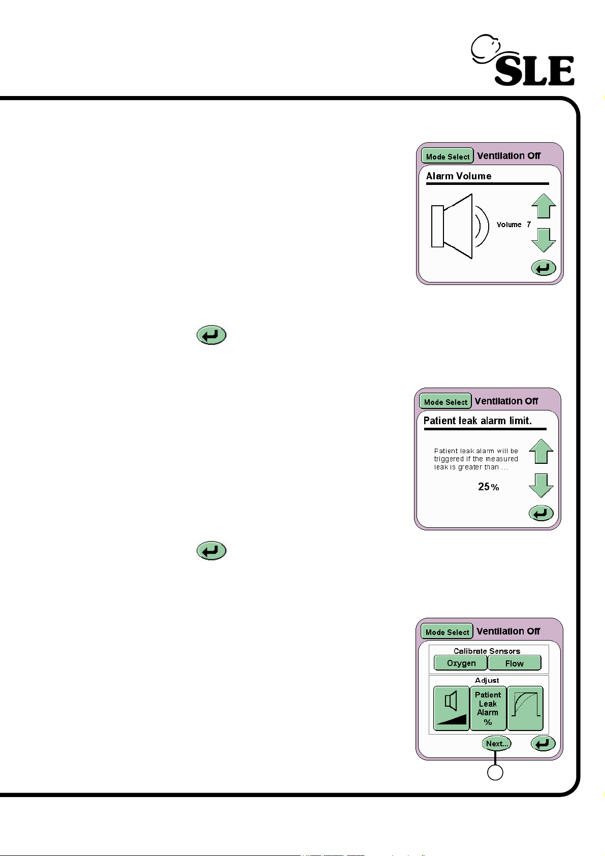
7.5.4 Alarm Volume
On pressing the Volume Control button (G) the
Alarm Volume panel will be displayed.
The alarm volume panel allows the user to set the
alarm sounder volume between 7 maximum and 3
minimum. The sounder level settings below 3 can
not be selected as normal background noise could
mask the alarm.
The setting 1 is the minimum sound level as stated
in the standard BS EN 475: 1995. This setting is
used by ventilator in situations where the alarm sounds would be a nuisance.
The Return button returns the user to the Services panel.
7.5.4.1 Patient Leak Alarm Limit
On pressing the Patient Leak Alarm % button (H)
the Patient Leak Alarm Limit panel will be
displayed.
The patient leak alarm limit panel allows the user to
increase or decrease the alarm threshold
percentage.
For a detailed description of the Patient leak alarm
limit see “Patient Leak Alarm” on page 143.
The Return button returns the user to the Services panel.
7.6 More Options Panel
The Next... button (K) advances the user to the
More Options panel.
K
Page 51 of 292
Page 52
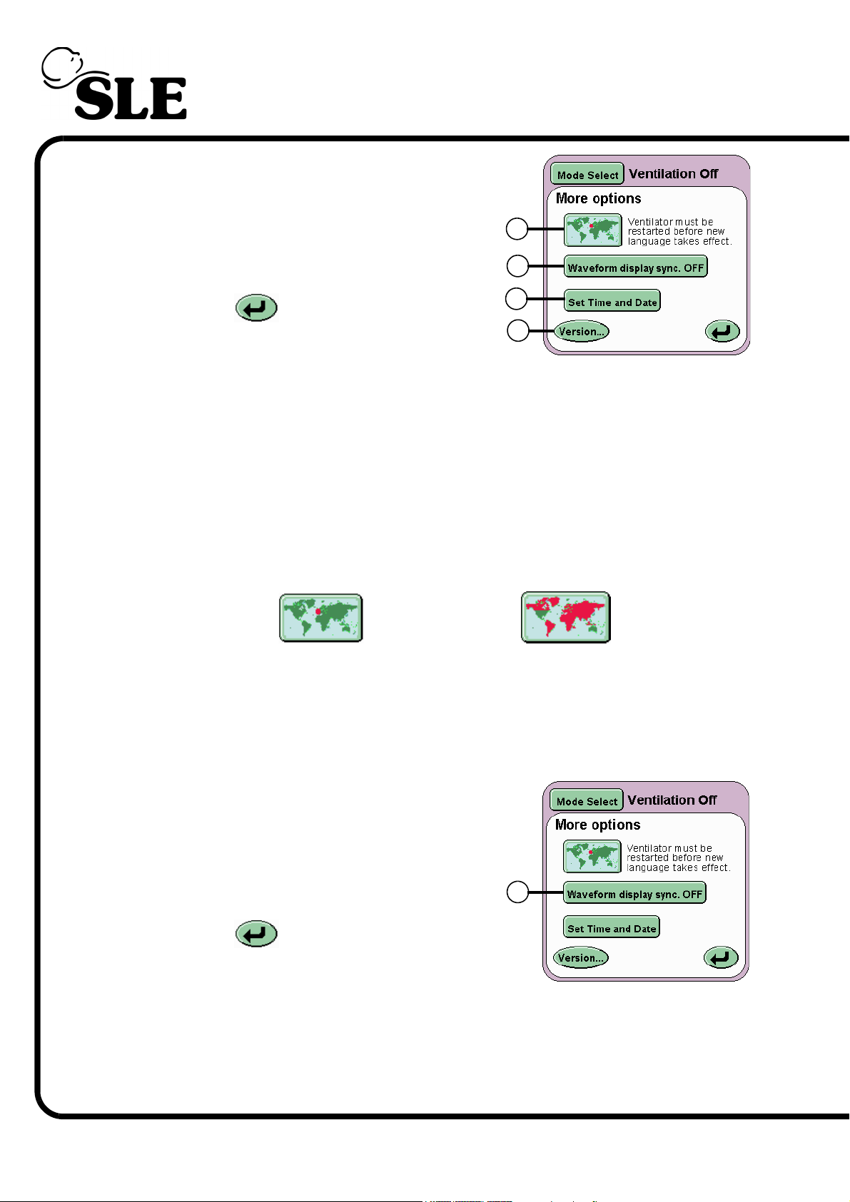
Displayed on this panel are four buttons:
Language Toggle button (L)
Waveform Display Sync button (M)
Set Time and Date button (N)
Version.. (O)
L
M
The Return button returns the user to
the Services panel.
7.6.1 Language Toggle
The ventilator software can be supplied to the user with a secondary language
installed. The user needs to refer to the user manual that accompanies the
ventilator to find which language apart from English is installed. See page 2 for
the software version number and language couple.
To change the language of the user interface press the Language Toggle button
(L) and hold for 2 seconds, so the map turns red. Turn OFF and restart the
ventilator. The ventilators user interface will now be in the second language.
Ventilator set to
English
N
O
Ventilator set to
foreign language
Repeat the process to return the user interface language to English.
7.6.1.1 Waveform Display Sync
The Waveform Display Sync button (M)
overlays the waveforms from one sweep with
that from the next. See “Waveforms” on
page 72.
The Return button returns the user to
the Services panel.
M
Page 52 of 292
Page 53
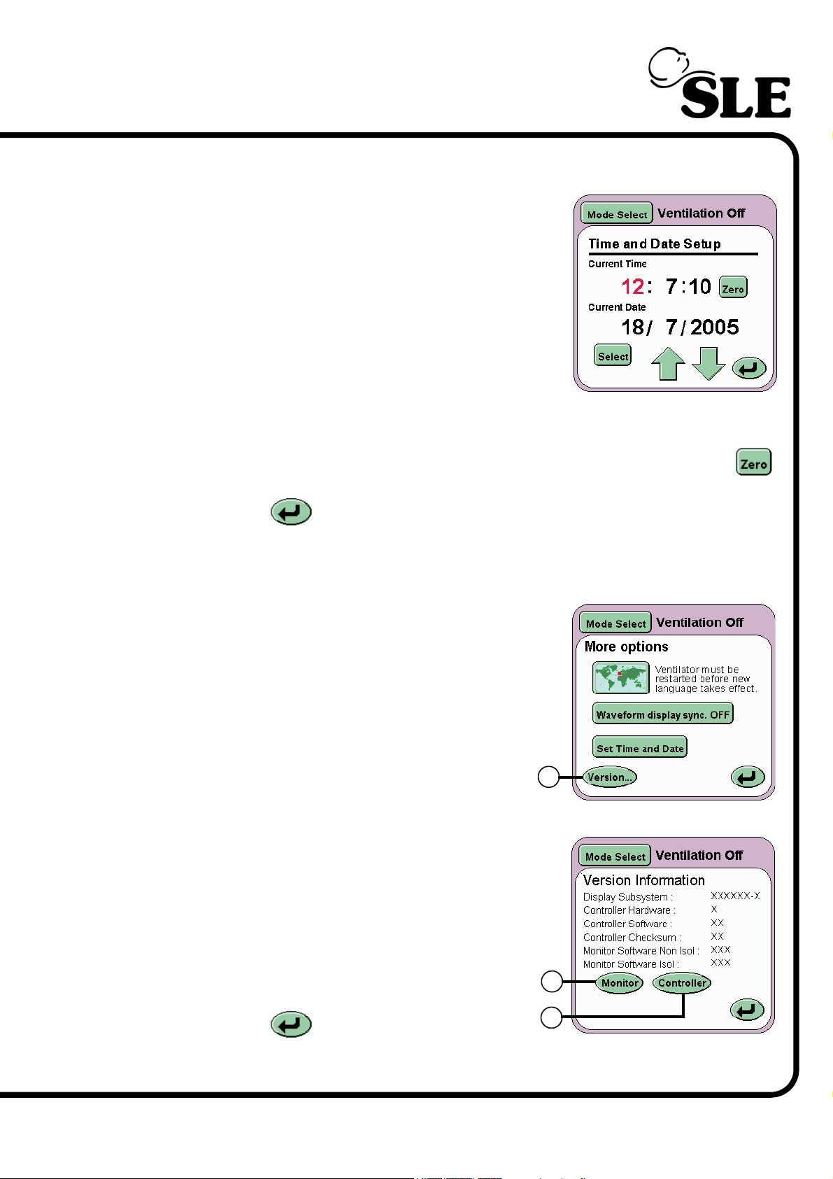
7.6.1.2 Set Time and Date
The Set Time and Date button (N) allows the user
to set the internal clock and calendar of the
ventilator. The date and time is displayed above the
pressure waveform window.
Note: the ventilator uses the 24 hour clock system
and Day/Month/Year date system.
The value highlighted in red can be changed by
incrementing the value up or down using the arrow
controls.
Pressing the Select button highlights the next value to be changed. The seconds
can not be modified in this manner but can be zeroed using the Zero button .
The Return button returns the user to the More Options panel.
7.7 Version Information Panel
The Version button (O) advances the user to
the Version Information panel.
Displayed on this panel are two buttons:
Monitor (P)
Controller (Q)
The panel also displays the software and
hardware versions of the subsystems installed
in the ventilator.
O
P
The Return button returns the user to
the More Options panel.
Q
Page 53 of 292
Page 54
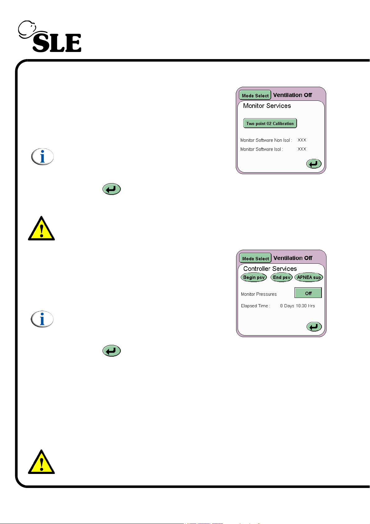
7.7.1 Monitor Services
On pressing the Monitor button (P) the Monitor
services panel will be displayed.
This panel displays the Two point O2 calibration
button and the software version numbers for the
monitor subsystem.
Note: See section 21. on page 214 for
information on the two point oxygen sensor
calibration.
The Return button returns the user to the Version Information panel.
7.7.2 Controller Services
Warning: The controller services should only be used by Qualified Service
Personnel.
On pressing the Controller button (Q) the
Controller services panel will be displayed.
The controller services panel displays four buttons.
Begin psv, End psv, Apnoea sup and the Monitor
pressures button (here shown set to Off).
Note: The controller services are locked and
require activation. (The activation can only be
carried out by qualified service personnel).
The Return button returns the user to the Version Information panel.
Apnoea sup, End psv and Begin psv buttons send a internal pulse to mimic the
Beginning and End of a pressure supported breath or a back-up breath. These
pulses do not affect the operation of the ventilator.
The monitor pressure button toggles the top waveform to show Fresh Gas
pressures against time or Blender input pressures against time. Off shows the
proximal airway pressure against time. When the monitor pressure button is set
to one of the two options an error message is displayed below the alarm window
(Controller not responding).
Page 54 of 292
Warning: Do not use the ventilator clinically when monitoring either Fresh
Gas Pressures or Blender Input Pressures via the controller services panel.
Page 55
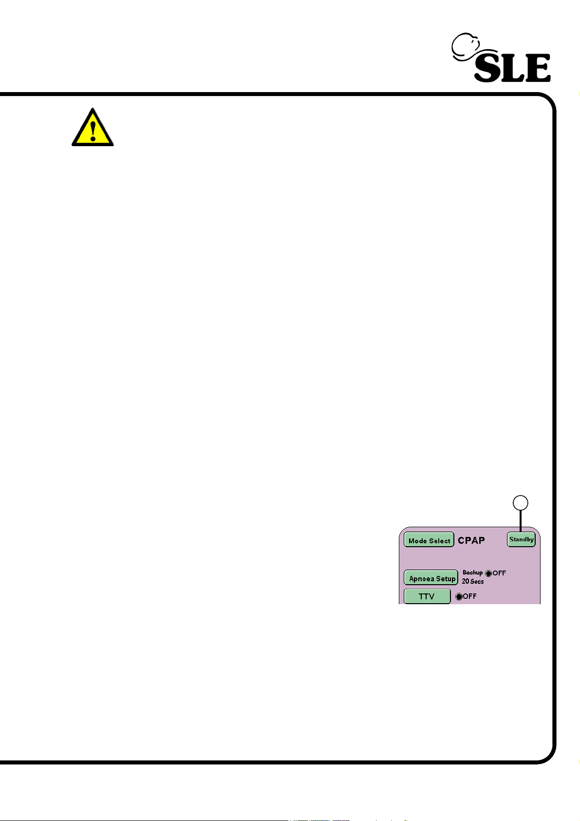
Warning: Do not use the ventilator if the error message CONTROLLER NOT
RESPONDING is displayed. Refer the ventilator to Qualified Service
Personnel.
The panel also displays software version numbers and controller checksum for
the controller subsystem. The Elapsed time counter shows the accumulated days
and hours the ventilator has been turned on.
7.8 Mode Panel Functions in a Ventilation Mode
For each ventilation mode, extra mode specific functions are displayed in the
panel (except HFO Only).
SLE4000 & SLE5000
For CPAP Apnoea Setup, Set Trigger and TTV buttons.
For CMV TTV button.
For PTV Apnoea Setup, Set Trigger and TTV buttons.
For PSV PSV setup, Apnoea Setup, Set Trigger and TTV buttons.
For SIMV PSV setup, Apnoea Setup, Set Trigger and TTV buttons.
SLE5000 Only
For HFO+CMV HFO Activity
The Mode Select button, Standby button and Service Data button are common
to all mode panels.
7.8.1 Standby Button (All modes)
The Standby button (R) suspends the current
mode of ventilation for 90 seconds. Though
ventilation has ceased the ventilator maintains the
mean pressure.
The Standby button has to be pressed for 3
seconds before ventilation is suspended.
Ventilation will restart after the 90 second period.
Ventilation can be restarted at any time within the 90 second standby period by
repressing the Standby button.
All alarms generated by entering the standby mode are displayed in the alarm
panel, but the audible component is reduced to the minimum value.
R
When restarting ventilator will carry out a “soft start” to ventilation, gradually
increasing the pressure until the user setting are achieved.
Page 55 of 292
Page 56
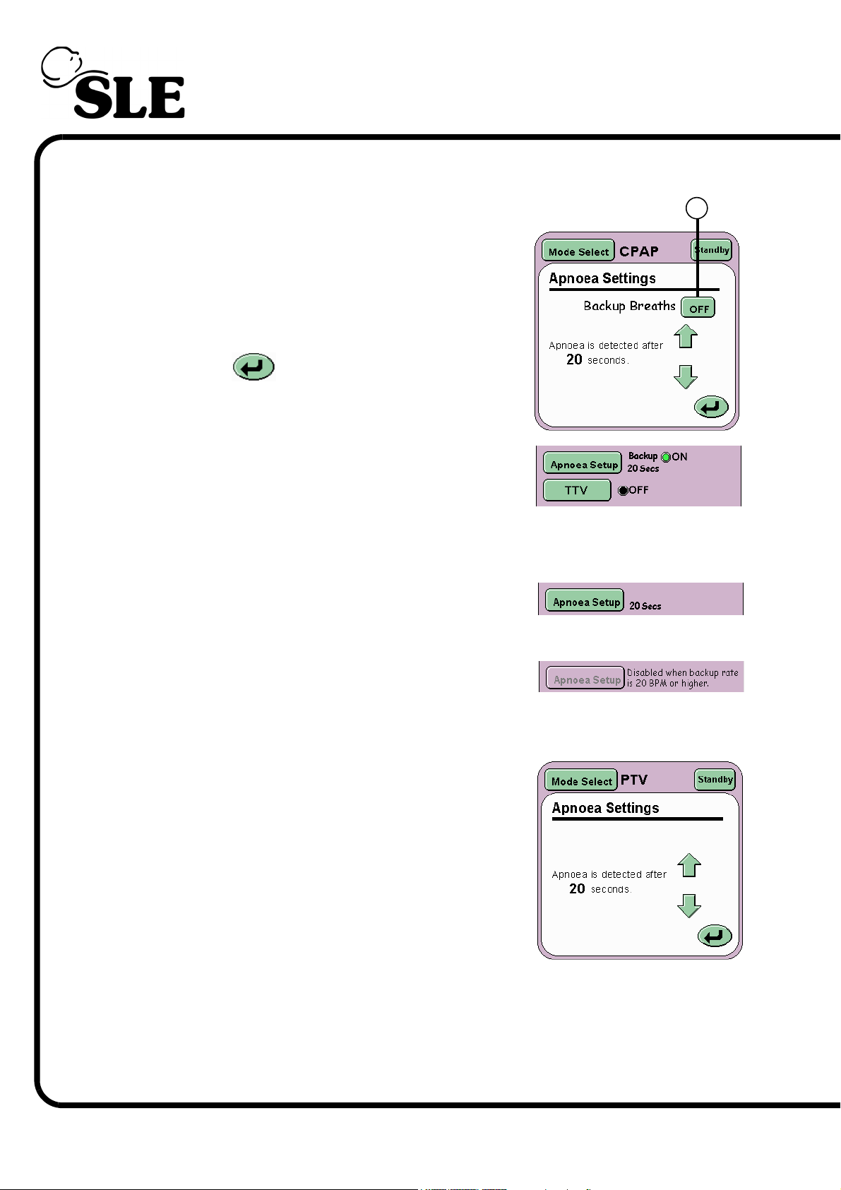
7.8.2 Apnoea Setup for CPAP
The Apnoea Settings panel allows the user to set
the Apnoea detection time and to activate backup
breaths if apnoea is detected.
The Backup breaths function is activated by the
ON/OFF toggle button (S) and the Apnoea Detect
time is controlled by the Arrow controls.
The Return button returns the user to the
current mode panel.
In the mode panel the function indicator will change
from black to green and display the word ON.
7.8.3 Apnoea Setup for PTV, PSV and SIMV
For PTV, PSV and SIMV the Apnoea setup button
only becomes active when the backup breath rate is
19 BPM or lower.
S
At 20 BPM and above the Apnoea alarm is inactive.
The ventilator defaults to 20 BPM so the Apnoea alarm is inactive.
The Apnoea Settings panel when active allows the
user to set the Apnoea detection time only.
The user at Backup rates of 19 BPM or lower can
set the apnoea detection time from 5 to 60 seconds.
The default is value is 20 seconds.
Page 56 of 292
Page 57
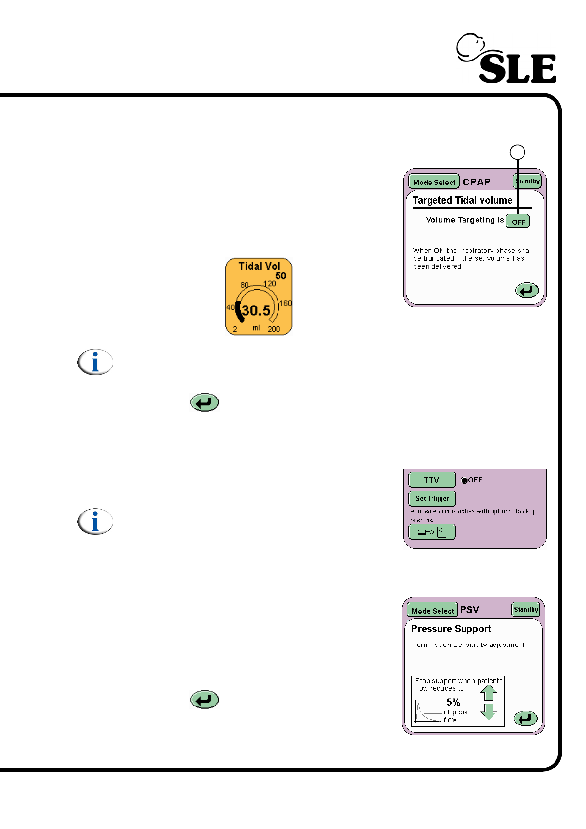
7.8.4 TTV for CPAP, PSV, PTV & SIMV
The Targeted Tidal Volume panel allows the user
to turn ON or OFF volume targeting.
Volume targeting (TTV) is activated by the ON/OFF
toggle button (T).
When Volume Limiting is ON the Tidal volume
parameter panel appears allowing the Tidal Volume
limit to be set.
Note: When TTV has been selected the inspiratory time (Ti) and the Peak
Inspiratory Pressure (PIP) change to Max Ti and Max PIP.
T
The Return button returns the user to the current mode panel.
7.8.5 Set Trigger for CPAP, PSV, PTV & SIMV
The Set Trigger button activates the breath
detection threshold in the flow waveform window.
Note: The breath detection threshold can still be
activated through the alarm panel. See “Alarm
and Breath Detection Thresholds” on page 62.
7.8.6 Pressure Support in PSV
The Pressure Support panel allows the user to set
the Stop Support when patient flow reduces to
percentage (Termination Sensitivity) .
The panel allows the user to increase or decrease
the percentage value via the arrow buttons.
The Return button returns the user to the
current mode panel.
Page 57 of 292
Page 58
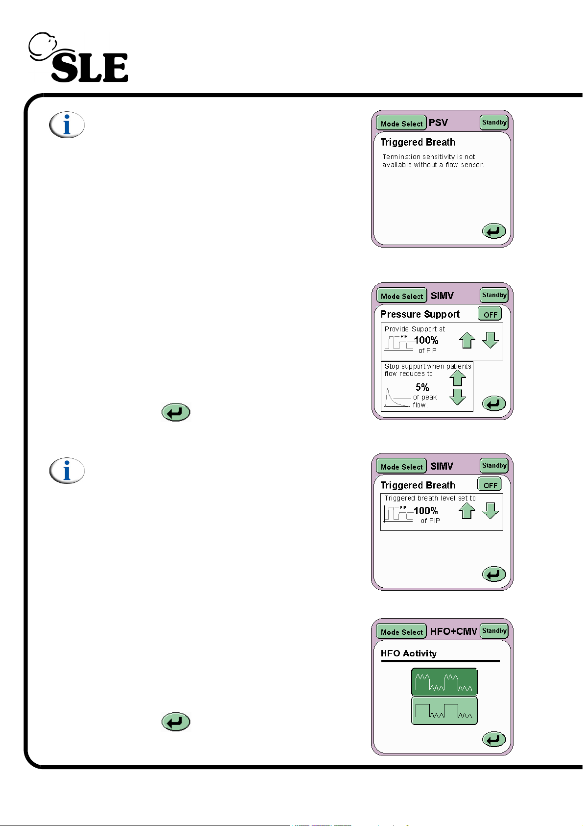
Note: When the ventilator is being used without
a flow sensor the user can no longer set the
termination sensitivity as this is a flow
dependant parameter.
7.8.7 Pressure Support in SIMV
The Pressure Support panel allows the user to set
the Provide Support at percentage, and the Stop
Support when patient flow reduces to
percentage (Termination Sensitivity) of the SIMV
breath.
The panel allows the user to increase or decrease
the percentage values via the arrow buttons.
The Return button returns the user to the
current mode panel.
Note: When the ventilator is being used without
a flow sensor the user can no longer set the
termination sensitivity as this is a flow
dependant parameter.
7.8.8 HFO Activity (SLE5000 Only)
The HFO activity panel allows the user to toggle
between oscillations in both inspiratory and
expiratory phases of the CMV waveform or just the
expiratory phase.
Page 58 of 292
The Return button returns the user to the
current mode panel.
Page 59
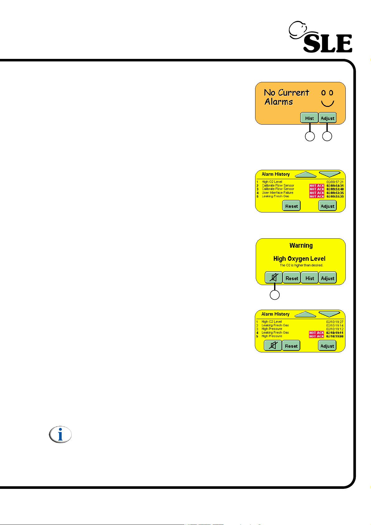
7.9 Alarm Panel
The Alarm Panel displays all the alarm messages.
The Adjust button (U) activates the alarm setup
panel in the Mode panel area, plus any alarm
threshold in the waveform windows. It also allows
the user to jump directly to the flow sensor and
oxygen cell calibration panels when their respective
alarms are triggered (provided no other higher
priority alarms are active).
The Hist button (V) changes the panel to display all
the previous alarm conditions that have occurred.
Up to 100 alarm conditions can be displayed in the
panel. The user can scroll through the alarms by
using the up and down arrow buttons in the panel.
The alarms are marked with the day and time of
activation.
When an alarm condition is active the panel flashes
between red and yellow, which indicates what alarm
has been triggered. The panel will only show the
highest priority alarm.
V
U
More than one alarm can be active at the same
time.
W
When an alarm is active the user can acknowledge
the alarm by pressing the HIST. button (V).
Acknowledging an alarm condition does not cancel
the alarm but allows the user to view the Alarm
History.
If there is more than one alarm active the Alarm History panel will show these
conditions as NOT ACK, but the time of the alarm will be the same as that of the
first alarm in the alarm history.
Pressing the Mute button (W) will cancel the audible component of the alarm for 1
minute. If a new alarm condition is triggered this new alarm will override the mute
setting of the previous alarm
Note: Some alarms cannot be muted.
Pressing Reset will return the Alarm panel to the No Current Alarms view and
cancel the audible alarm only if that alarm condition has been cleared. If more
than one alarm condition is present, pressing reset will clear the cleared alarm
condition from the panel and allow the next highest priority alarm to be displayed.
Page 59 of 292
Page 60
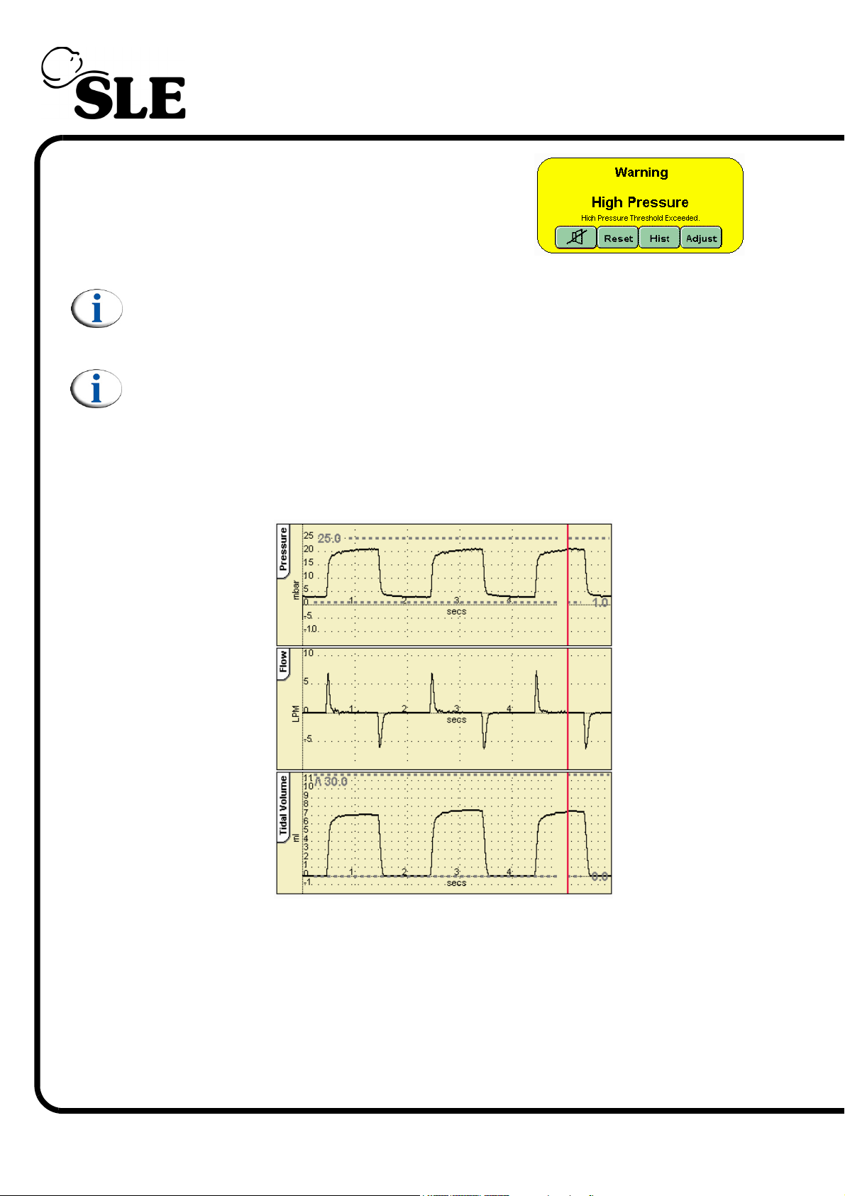
When an alarm condition has been cleared without
it either being acknowledged or reset the panel will
stop flashing and will change colour to yellow.
Note: Please refer to “Alarm Descriptions and Actions to be Taken” on
page 225 for a detailed list of ventilator alarms.
Note: The battery fail alarm is an audible only alarm, no visual indication is
given.
7.10 Default Waveform Windows
The windows display the waveforms and loops generated during ventilation.
The default waveform layout.
Page 60 of 292
The SLE4000 ventilator default setting is to display: Pressure, Flow and Tidal
volume waveforms for CPAP, CMV, PTV, PSV and SIMV.
The SLE5000 ventilator default setting is to display: Pressure, Flow and Tidal
volume waveforms for CPAP, CMV, PTV, PSV, SIMV and HFO. For HFO+CMV
the ventilator will only display Pressure and Flow waveforms.
The red sweep bar tracks across the windows updating the display.
Page 61
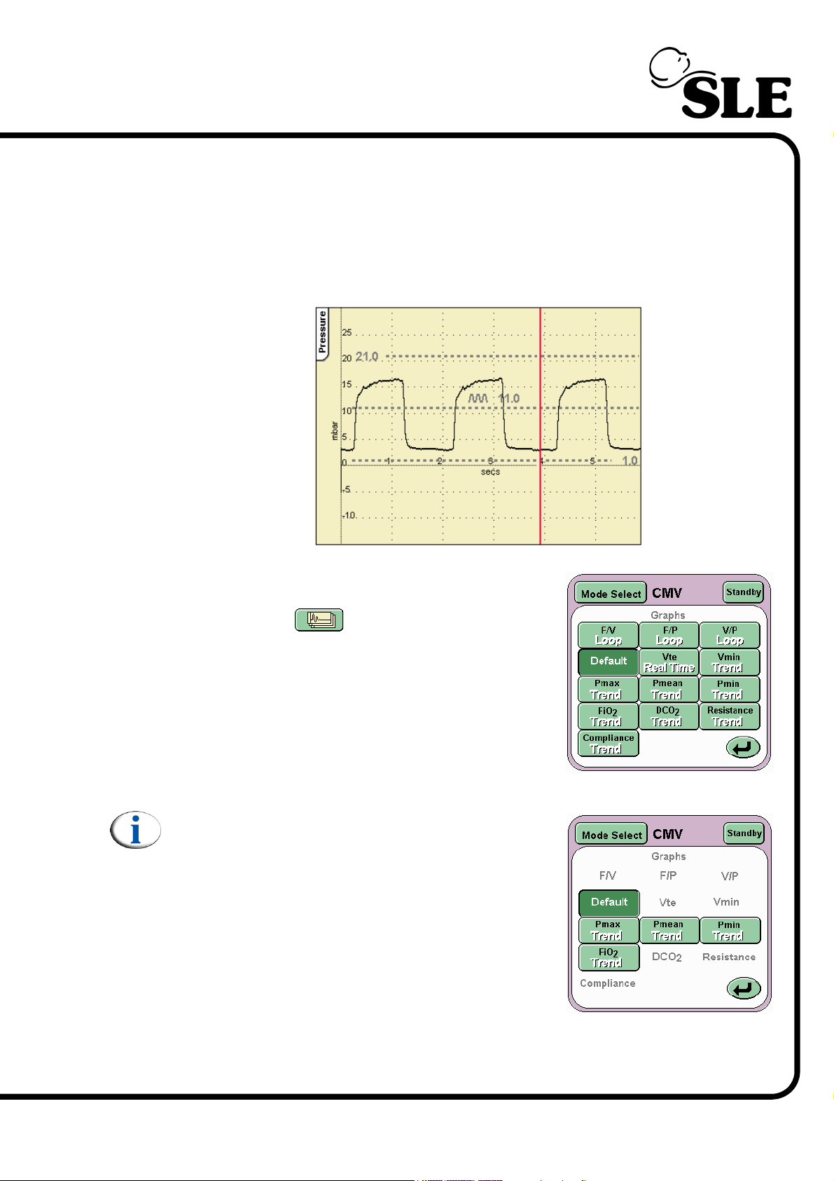
The alarm thresholds are also displayed in these waveform windows.
The scales in waveform windows autoscale to match the set ventilation
parameters.
When the ventilator is used without a flow sensor the default layout changes to
exclude flow related waveforms.
The ventilator can also display loops and trends.
These are accessed from the Waveform Display
Options button .
The button activates the Loops And Waveforms
panel.
From this panel you can select the combination of
loops and waveforms required.
Note: Flow related buttons will not be displayed
when the ventilator is used without the flow
sensor.
For a full explanation of the loops, trending, and waveforms see “Loops, Trends &
Waveforms” on page 72.
Page 61 of 292
Page 62
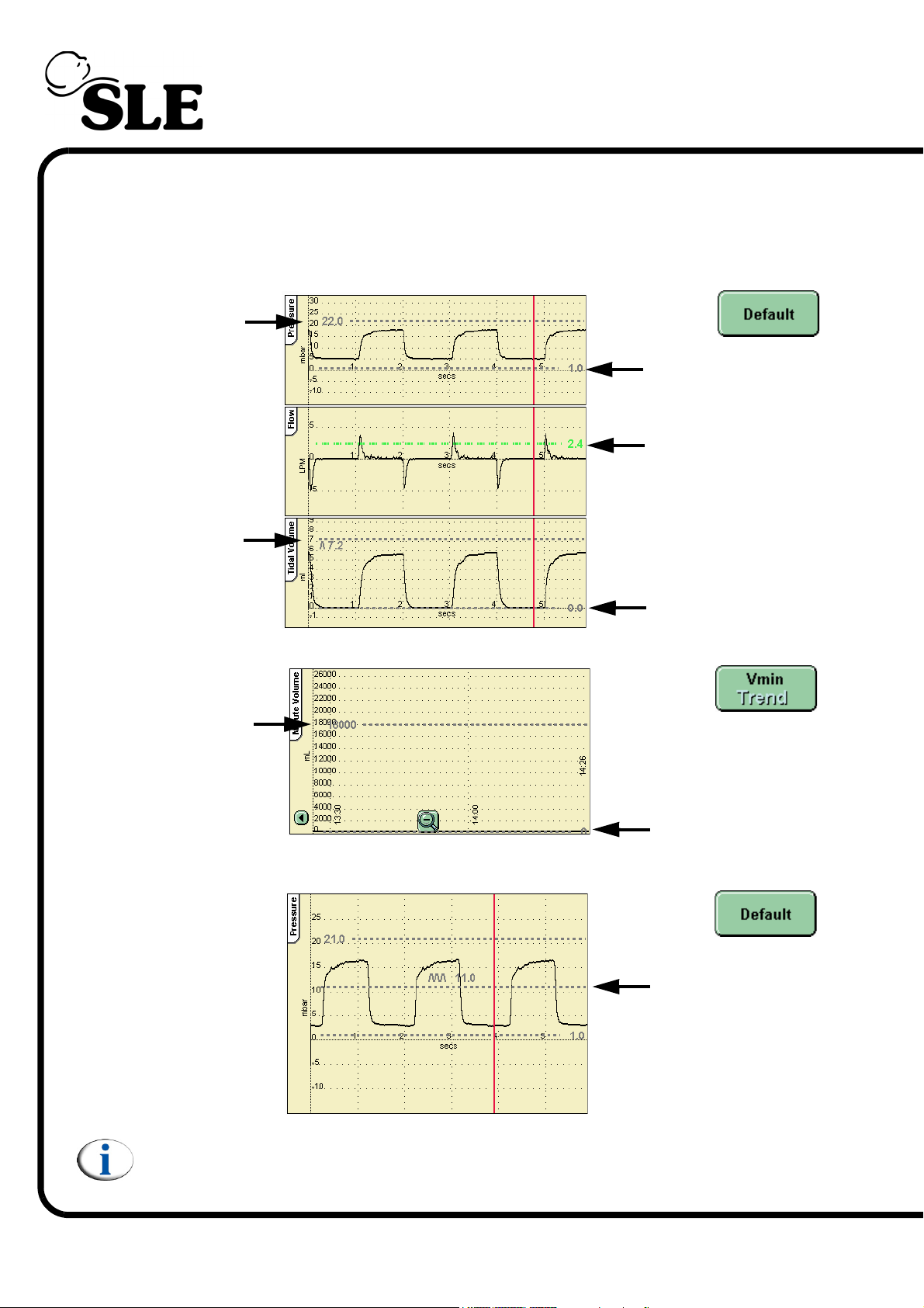
7.11 Alarm and Breath Detection Thresholds
The ventilator has the following user adjustable alarms and breath detection
threshold.
Default waveform windows (with flow sensor connected):
High Pressure
High Tidal Volume
Low Pressure
Breath detection
Low Tidal Volume
Minute volume graph (selected from graph options button):
High Minute
Volume
Cycle Fail Alarm (when no flow sensor connected):
Low Minute
Volume
Cycle Fail
Page 62 of 292
Note: When the using the ventilator without a flow sensor the following
thresholds are not present, High & Low Tidal volume, High & Low Minute
Volume and the breath detection.
Page 63
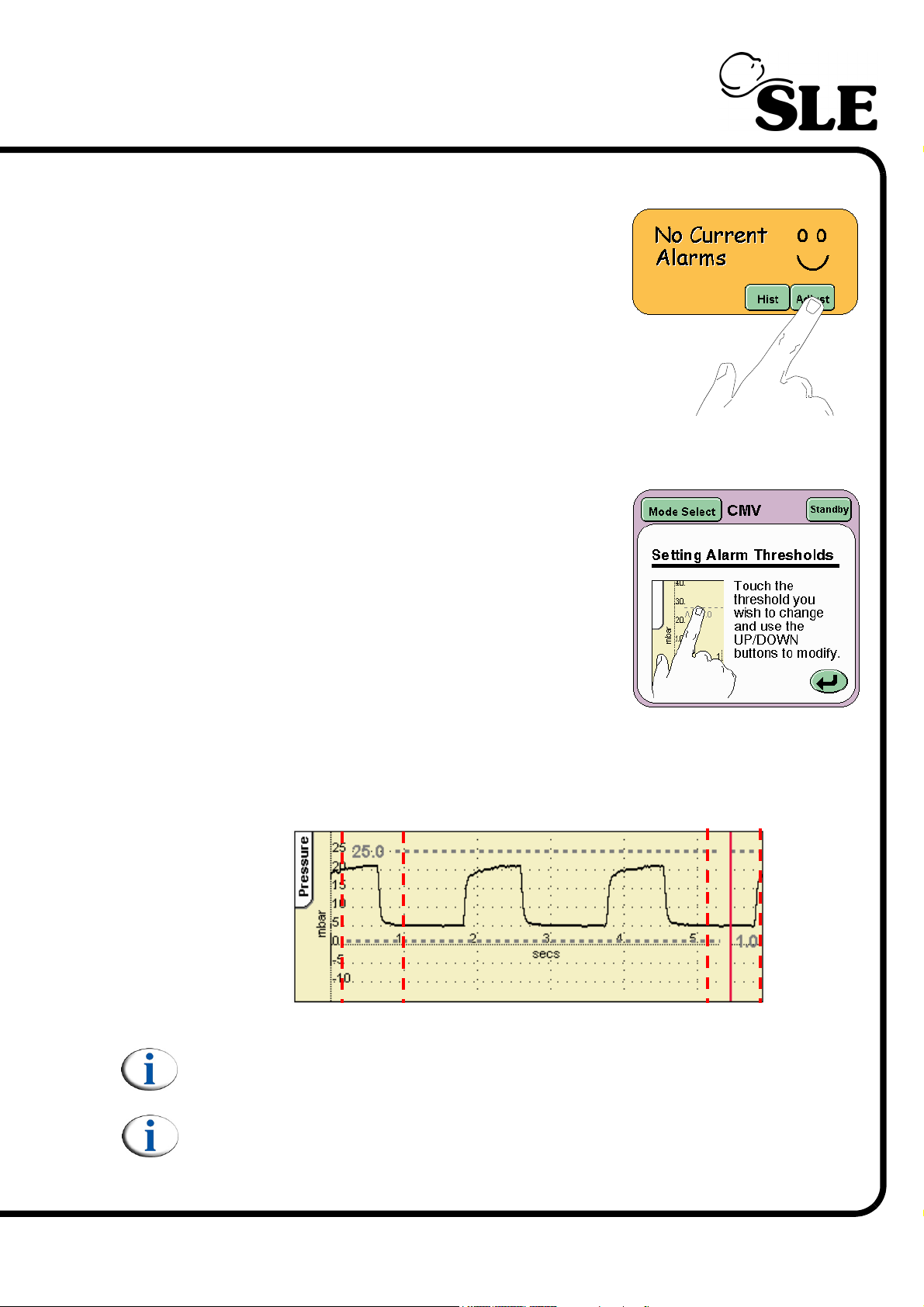
7.12 How to Set an Alarm Threshold
To adjust an alarm threshold press the Adjust
button in the alarm panel.
If no alarm condition is present the user will have to
select the alarm threshold for modification.
In an alarm condition the user on pressing the
Adjust button will find that the crossed alarm
threshold will automatically be selected. (The alarm
will flash).
In the mode select panel a new panel appears
giving a description on how to set the alarm
thresholds, this panel indicates that the alarm
thresholds can be modified. The alarm thresholds
remain adjustable for 5 seconds after the last
adjustment, after that the user needs to re-activate
them again by pressing the adjust button.
The alarm threshold can be selected by touching in the alarm threshold
adjustment column or the text and numerical value in the waveform window. The
adjustment column is an area above or below an active alarm threshold text. The
diagram below details the columns present in the pressure wave form window.
Note: The dotted lines do not appear in the actual waveform window. They
are for graphical purposes only.
Note: When using the ventilator without a flow sensor fitted a cycle fail
alarm threshold will be present.
Page 63 of 292
Page 64
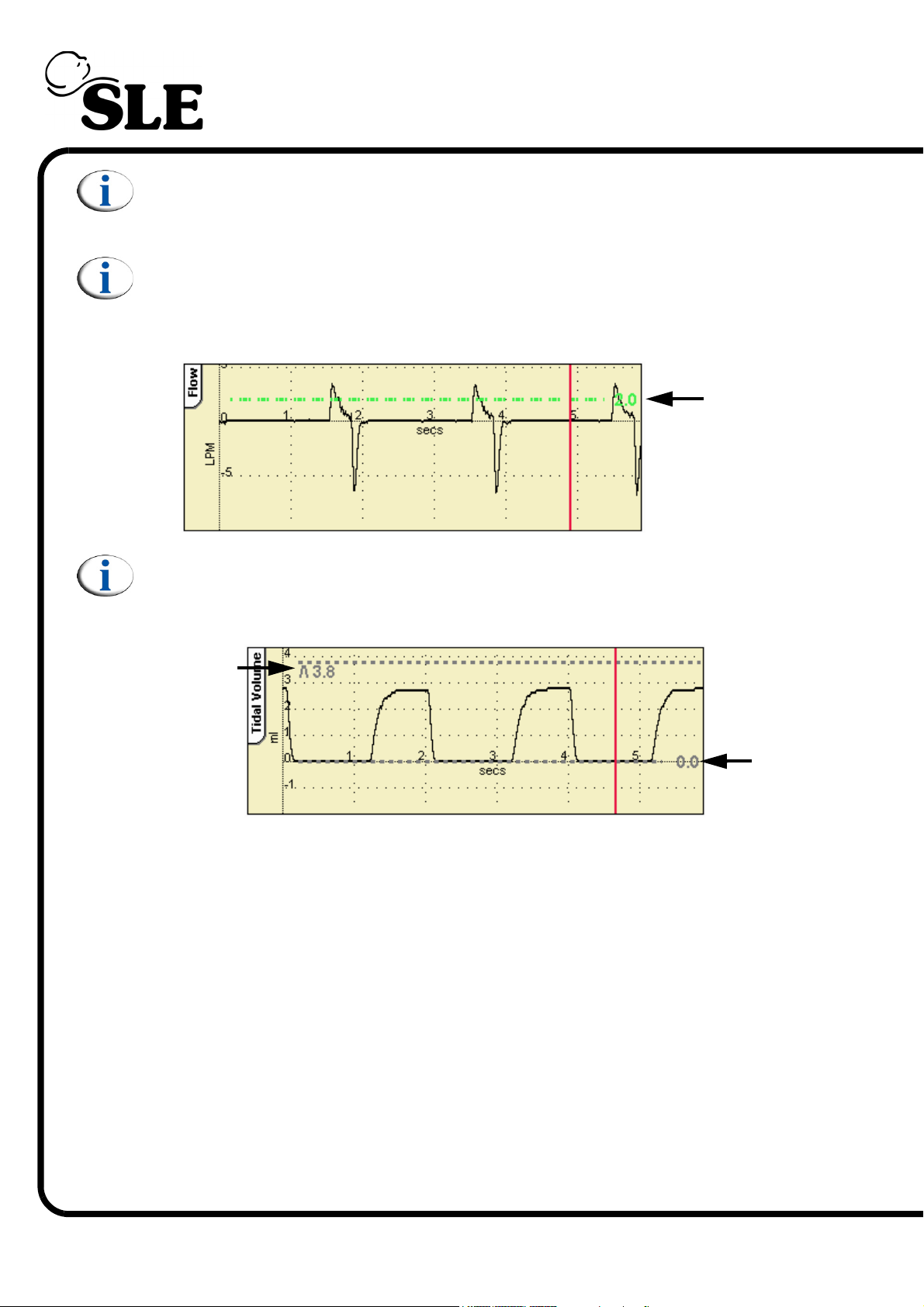
Note: The High and Low Pressure Alarm thresholds auto track the pressure
waveform by 5mbar for conventional modes of ventilation and 10mbar for
HFO modes.
Note: In CPAP, PTV, PSV and SIMV modes, the Flow window has a breath
detection threshold. This threshold is activated by the Set Trigger button or
can modified in the same manner as an alarm threshold as described
above.
Breath
Detection
Note: In all conventional modes there is a High and Low Tidal volume alarm
threshold. These thresholds are modified in the same manner as an alarm
threshold.
High Tidal
Volume
Low
Tidal
Volume
To modify an alarm threshold the user should first press the adjust button in the
alarm panel. The user should then touch the adjustment column or the symbol
and numerical value of the alarm threshold required in the waveform window.
The alarm threshold changes colour to red and starts to flash, indicating that the
alarm can be modified and the adjustment arrows should appear in the lower
right-hand corner of the screen.
The alarm threshold can now be modified using two methods.
The first method is by using the up and down arrow keys in the lower right-hand
corner of the screen.
Page 64 of 292
Page 65
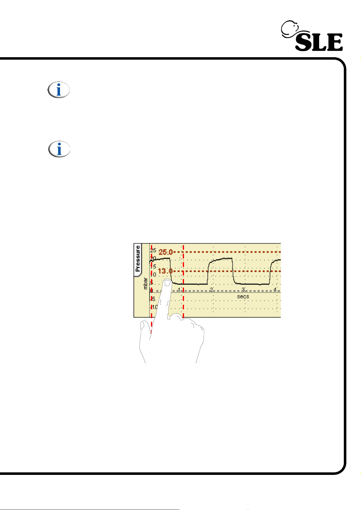
Note: The user can only adjust the alarm thresholds to 15mbar above the
maximum PIP or 15mbar below the minimum pressure in conventional
ventilation or 20mbar above the maximum PIP or 20mbar below the
minimum pressure in HFO or combined mode ventilation (HFO + CMV). This
safety feature stops the user setting the alarm threshold so high that in
practice the alarm is turned off.
Note: The user must be made aware that the Low Alarm threshold will only
autotrack down to 1mbar in conventional ventilation. If the user wishes to
set the alarm lower than 1mbar then this has to be done manually. If the
alarm threshold is manually set lower than 1mbar and a pressure related
parameter is adjusted the low alarm threshold will return to 1 mbar. The
user will have to manually re-adjust the alarm threshold to the required
level.
The second method is by touching the screen above or below the text of the
highlighted alarm but within the adjustment column. This is a coarse method of
adjustment.
The illustration shows the High alarm being coarsely set from 25 mbar to 13 mbar.
©
Fine adjustment can be made by use of the arrows displayed in the lower right
hand corner of the screen.
Page 65 of 292
Page 66
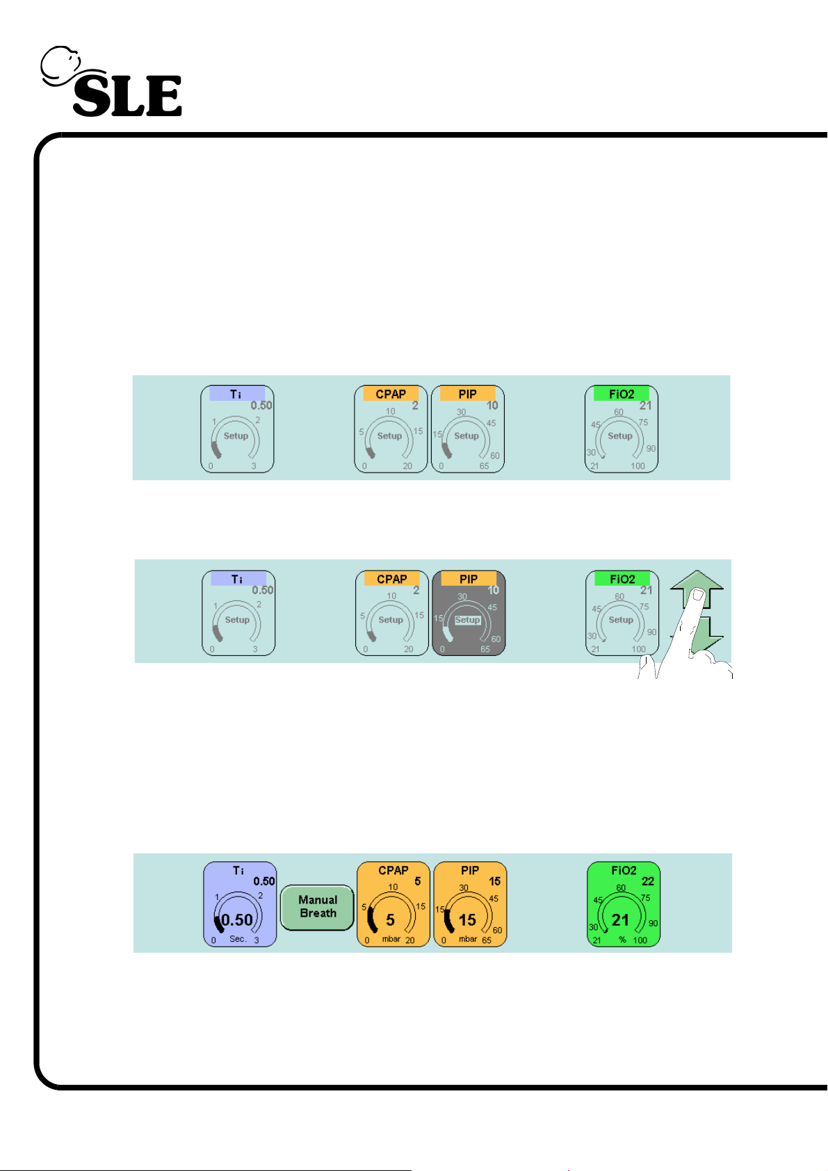
7.13 Ventilation Parameters
Each ventilation mode has a number of parameters that have to be changed to
meet the clinical requirements. The interface displays the user definable
parameters at the bottom of the touch screen. On power up the ventilator defaults
to the stand by mode and only displays the FiO2 parameter.
When changing from stand-by to another mode of ventilation the parameters are
displayed in preview mode. (The example shown below is CPAP). This allows the
user to set the ventilator so it will not start at inappropriate settings when the
mode is confirmed.
The parameters can be selected and modified by touching the appropriate panel
and using the arrow buttons.
Preview Mode
The user will be unable to select parameters that would cause a dangerous
condition in the ventilation mode from the preview mode. On pressing the confirm
button the ventilator controls change to the ventilation mode and the ventilator
starts to ventilate at those settings. Any parameter that could not be selected in
the preview mode now becomes selectable. (These parameters default to safe
values).
Ventilation Mode
In the ventilation mode the manual breath button is displayed. The Manual breath
button will not appear in all modes of ventilation.
Page 66 of 292
Page 67
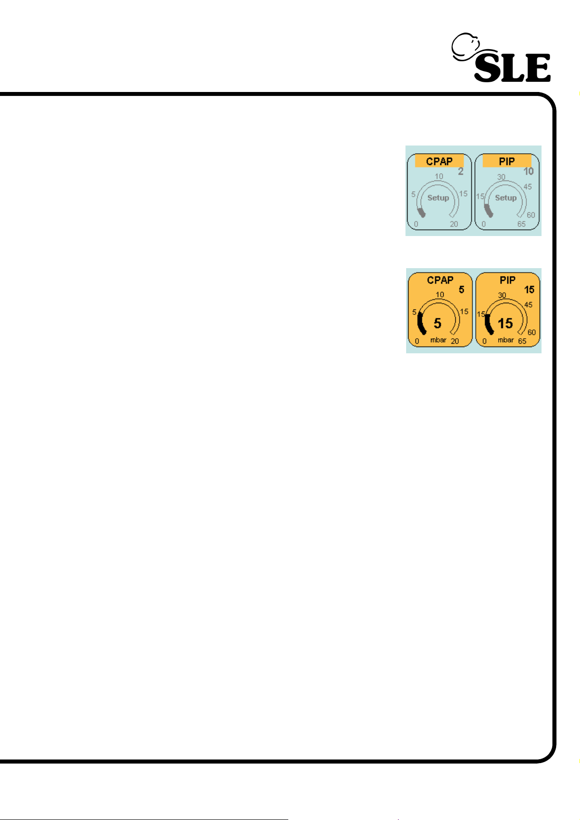
The parameters can be selected and modified in the same way as in the preview
mode.
In the preview mode the parameters panel displays
the set value.
In the ventilation mode the parameters panel displays
the measured value in the centre of the eyebrow and
the set value in the right hand corner.
Page 67 of 292
Page 68
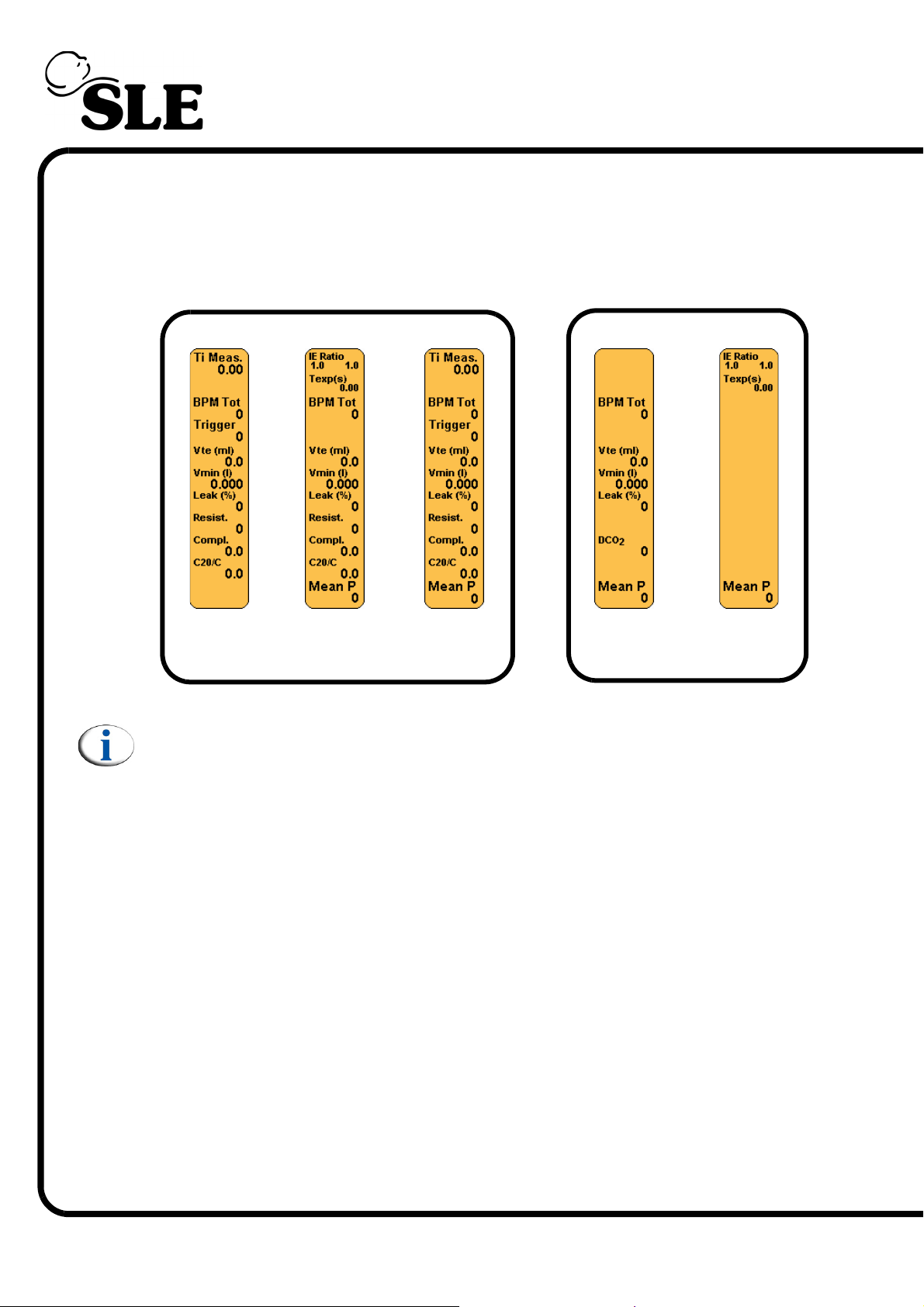
7.14 Lung Mechanics and Measurement Panel
This panel displays the measured and calculated ventilation parameters. When
no flow sensor is fitted only non flow based values are displayed. The panels
shown display the parameters for each ventilation mode.
SLE4000 & SLE5000
CPAP
Note: For CMV the IE ratio is replaced with measured Ti when TTV is on.
CMV
PTV
PSV
SIMV
SLE5000 Only
HFO
HFO+CMV
Ti Meas.
The measured inspiratory time, where the breath may be flow or volume
terminated and therefore shorter than the set inspiratory time. A measured value.
Trigger
The number of patient triggered breaths (updated every 2 seconds). A measured
value.
IE Ratio
Inspiratory to Expiratory ratio. A calculated value derived from the user set
inspiratory time against the time divided by the user set BPM minus the
inspiratory time.
BPM Tot
Total number of breaths detected by the ventilator. (Mechanical and patient
triggered). A measured value.
Vte (ml)
Expired volume. A measured value in millilitres.
Page 68 of 292
Page 69

Vmin (l)
Minute volume is the accumulated expiratory tidal volume over a one-minute
period. A measured value in litres.
Texp(s)
Total expiration time in seconds. A measured value.
Leak(%)
Percentage leak from the patient circuit. The difference between the expired
volume compared to the inspired volume as a percentage. A calculated value.
Resist.
Resistance of the patient to flow is the total change in the applied pressure to the
patient lung divided by the peak expiratory flow from the lung. A measured value.
Compl.
Compliance is the ratio of the change in lung volume to change in the applied
pressures. A calculated value.
C20/C
Is the ratio of the compliance during the last 20% of the respiratory cycle to the
total compliance. A calculated value.
DCO
2
Is a gas transport coefficient. A calculated value based on tidal volume and
frequency.
Mean P
The mean pressure. A measured value.
Page 69 of 292
Page 70
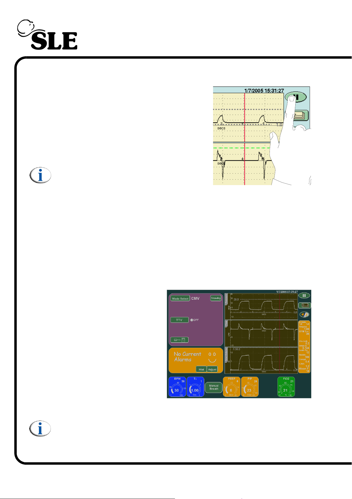
7.15 The Pause Button
The pause button is located in the top right hand
corner of the screen. Pressing the button will
freeze all the waveform windows for 1 minute.
Pressing the pause button at any time whilst the
screen is frozen will unfreeze the waveform
windows.
Note: The pause button does not affect the
users ability to adjust the alarm thresholds.
7.16 Night Button and Screen Lock
The Night and Screen Lock button locks the screen so no button presses are
registered (apart from the night and screen lock button) and changes the colours
on the screen to reduce the amount of light emitted. The ventilator uses a backlit
colour LCD that produces a large quantity of light.
Touching the button sets the screen to night mode. (See below for an example)
The screen will automatically
revert back to the standard colour
palette if an alarm condition
occurs.
Pressing the night and screen
lock button again will revert the
screen back to the standard
colour palette and release all the
controls.
Note: The screen may flicker shortly after activation as active panels and
controls time out and the display updates.
Page 70 of 292
Page 71

Loops, Trends & Waveforms
Page 71 of 292
Page 72

8. Loops, Trends & Waveforms
This chapter details the way the ventilator displays patient data. The ventilator
displays the realtime data collected from the proximal airway pressure transducer
and ET manifold mounted flow sensor to provide Pressure, Flow and Tidal
Volume waveforms. The ventilator can also display Loops based on the
pressure, flow and volume data, plus it can trend certain parameters against time.
The ventilator displays information in the following ways.
WAVEFORMS Pressure waveform
Flow waveform
Tidal volume waveform (Not available in HFO+CMV mode)
Note: The pressure waveform is always displayed when showing a loop or
trend.
LOOPS Flow Versus Volume loop (Not available in HFO+CMV mode)
Flow Versus Pressure loop (Not available in HFO & HFO+CMV mode)
Volume Versus Pressure loop (Not available in HFO & HFO+CMV mode)
TRENDS Minute Volume against time
Max Pressure against time
Mean Pressure against time
Min Pressure against time
FiO2 against time
DCO2 against time (Not available on the SLE4000)
Resistance against time
Compliance against time
8.1 Waveforms
The ventilators default display as already mentioned is the pressure, flow and
tidal volume waveforms. The waveforms appear in each window overlayed by a
grid which acts as a visual aid to measurement.
Within these windows and that of the Minute Volume window the user will find
the breath detection threshold and all the alarm thresholds that are user settable.
Note: The user can display the pressure waveform and the tidal volume
waveform only by selecting the Vte button in the Loops and Waveform
panel.
When changing the ventilatory parameters the axis in the windows autoscale to
best display the patient data.
The ventilator displays the waveforms within each window in real time. The
generated waveforms will slowly track across the window. The user can set all the
waveforms to be started in the same place by setting the Waveform display
sync to ON. (See “Waveform Display Sync” on page 52).
Page 72 of 292
Page 73
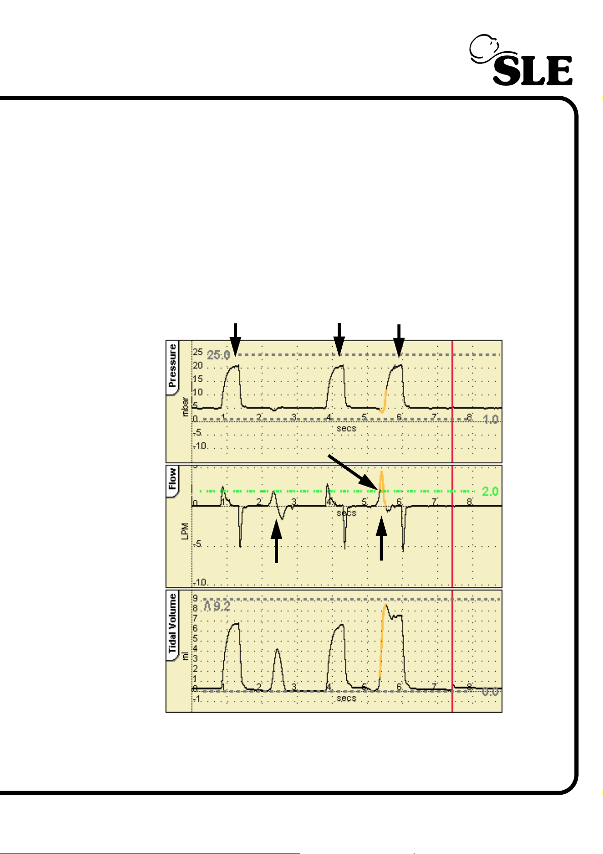
This means that the waveforms remain static (they do not creep from left to right)
in the windows.
For interactive ventilatory modes the data is enhanced by displaying the patient
trigger in a different colour.
To view the trigger point the ventilator colours the first 200 milli seconds orange,
after the patient effort that has crossed the breath detection threshold.
The illustration below shows the ventilator in SIMV mode where the first patient
breath did not cross the breath detection threshold. The second patient breath
crosses the breath detection threshold and the ventilator highlights the trigger
point.
Mandatory breaths
Trigger point
Patient attempt
below threshold
Triggered Breath
Patient attempt
crosses threshold
SIMV
Page 73 of 292
Page 74
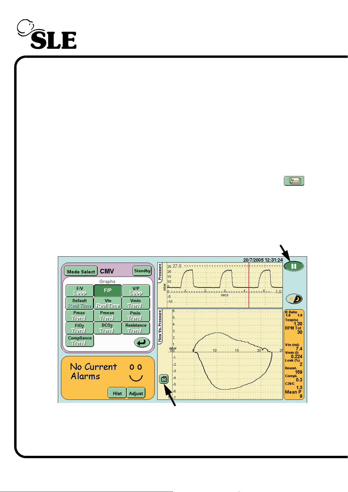
8.2 Loops
The ventilator displays the following three loops: flow versus volume, flow versus
pressure and volume versus pressure.
The ventilator draws three loops before refreshing the window. Each loop is
coloured differently in each three loop cycle. The colours being red, green and
black.
The ventilator has the ability to store one set of loops in its internal memory for
each type of loop. These stored loops are date and time stamped. When the
loops are retrieved from the memory they appear underneath the current active
loops.
The loops are accessed by pressing the Display Graphs Options button .
This activates the Loops and Waveform panel where the appropriate loop can be
selected.
8.2.1 Storing and Retrieving Loops.
8.2.1.1 To Store a Loop
Step 1. Pause the loop by pressing the Pause button.
Step 1. Pause button
Page 74 of 292
Step 2. Picture capture button
Step 2. If the loop is unsatisfactory release the pause button, and wait until a
suitable loop has been drawn before repressing the pause button. Once the
required loop has been captured, press the Picture capture button that appears
in the lower left hand corner of the loop window.
Page 75
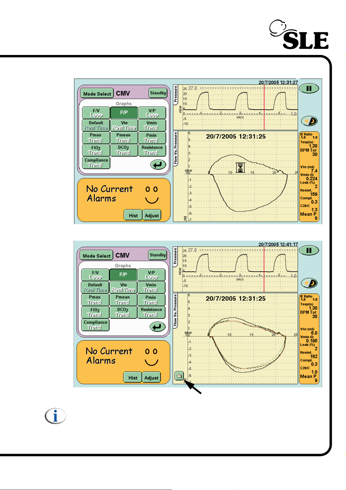
The ventilator will display the time and date that the loop was saved as it copies
the data to memory.
The ventilator will now display the saved looped and the current active loops.
Step 3. Stored Loop button
Note: When viewing a stored loop the active loops are shown as dashed
lines.
Step 3: To hide the loop press the Stored Loop button in the loop window. This
removes the stored loop and reverts to displaying the active loops as solid lines.
Page 75 of 292
Page 76
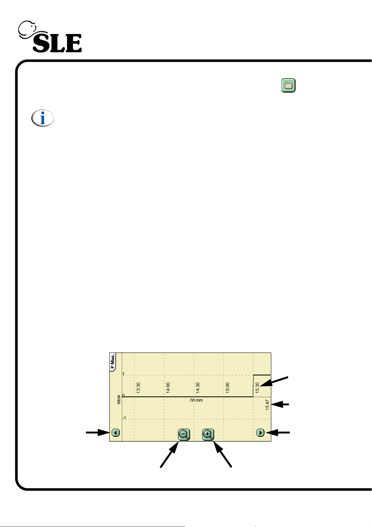
8.2.1.2 Retrieving Loops
The user can retrieve a loop by pressing the Stored Loop button in the
loop window.
Note: The ventilator will revert to the axis scale of the stored loop. This
could cause the current active loop to be drawn partially off the window.
8.3 Trends
The ventilator can display eight different trends, these being Minute Volume, Max
Pressure, Mean Pressure, Min Pressure, FiO
Compliance against time.
The ventilator stores 24 hours of trend data for all six trend types in a memory
buffer. This buffer holds the last 24 hours of stored data from the current
displayed time. As time progresses, data greater than 24 hours old is lost as new
data is added.
The trend windows by default display two hours of data (at power up). Once data
has started to be recorded the windows will automatically rescale to display one
hour of trend data. The user has the ability to zoom in to view one hours data or
zoom out to view a maximum of six hours data. The user can scroll back in time at
the selected magnification to view any recorded data in the previous 24 hours.
DCO2, Resistance and
2,
All the trend windows behave in the same manner with the exception of the
minute volume window which has the high and low minute volume alarm
thresholds. The minute volume alarm thresholds are only visible when the trend
window is scrolled to the current time.
8.3.1 Description of Trend Windows
The example window is that of Max pressure against time.
Scroll
Left
Reference
Time
Current
Time
Scroll
Right
Page 76 of 292
Zoom Out
Zoom In
Page 77

Ventilator Set-up
Page 77 of 292
Page 78
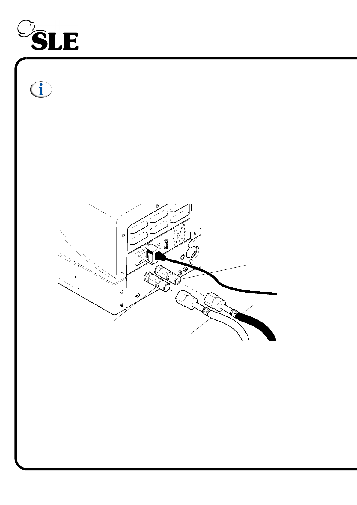
9. Ventilator Set-up
Note: The ventilator cannot be started on battery power.
9.1 Preparing the Ventilator for Use
To prepare the ventilator for functional testing and later patient ventilation, carry
out the following steps.
Step 1 Cleaning
Make sure that the ventilator has been cleaned in accordance with the
instructions in “Cleaning, Disinfection and Sterilization” on page 257.
Step 2 Connection of Oxygen and Air Hoses to the Ventilator
Air inlet
Air supply hose
Oxygen inlet
Oxygen supply hose
Connect the Air and Oxygen supply hoses to the ports on the rear of the
ventilator.
Page 78 of 292
Page 79
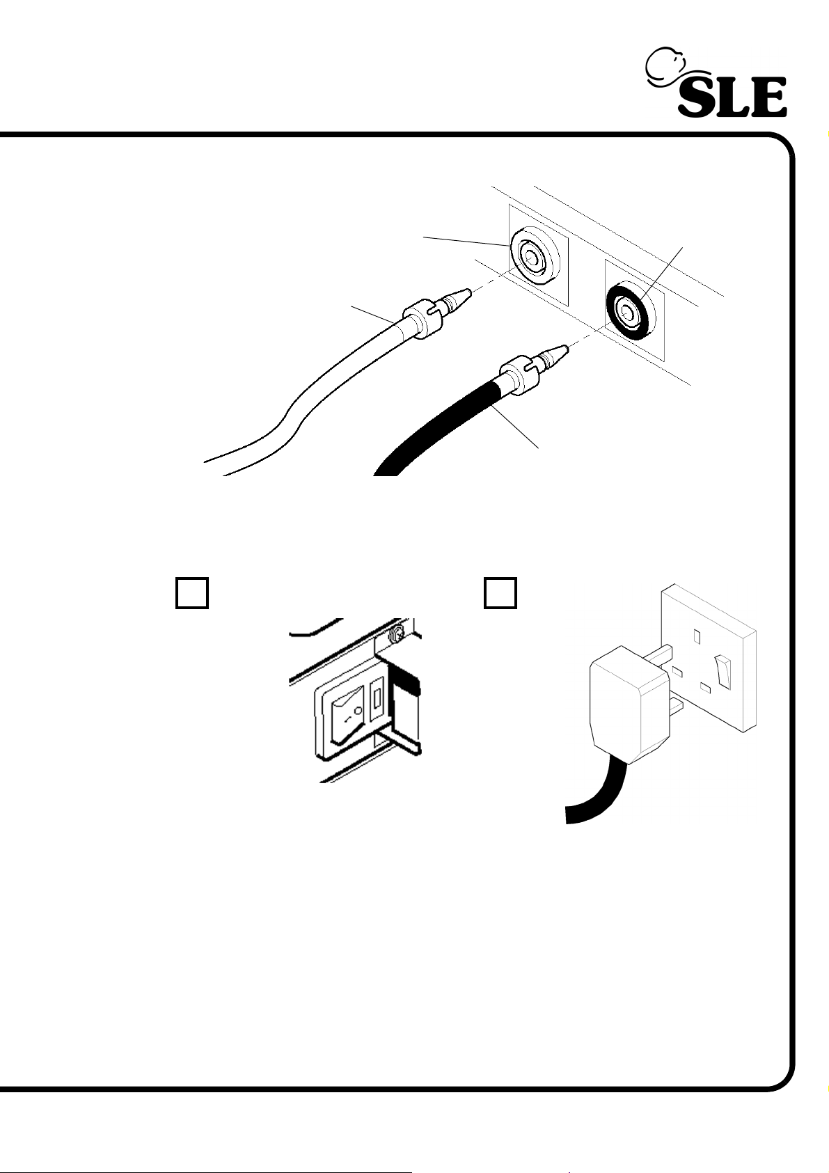
Step 3 Connection of Oxygen and Air Hoses to the Gas Supplies
Oxygen outlet
Oxygen supply hose
Plug into the gas supplies, at a gas pressure of about 4 bar.
Step 4 Connection of Mains Power
AB
Air outlet
Air supply hose
Check mains power switch is set to OFF (O)
Connect plug to mains
switch and turn on at
swtich
Check that the mains power switch on the ventilator is set to Off (A).
Connect the plug to a suitably rated and grounded mains supply. Turn on the
mains supply (B).
Page 79 of 292
Page 80
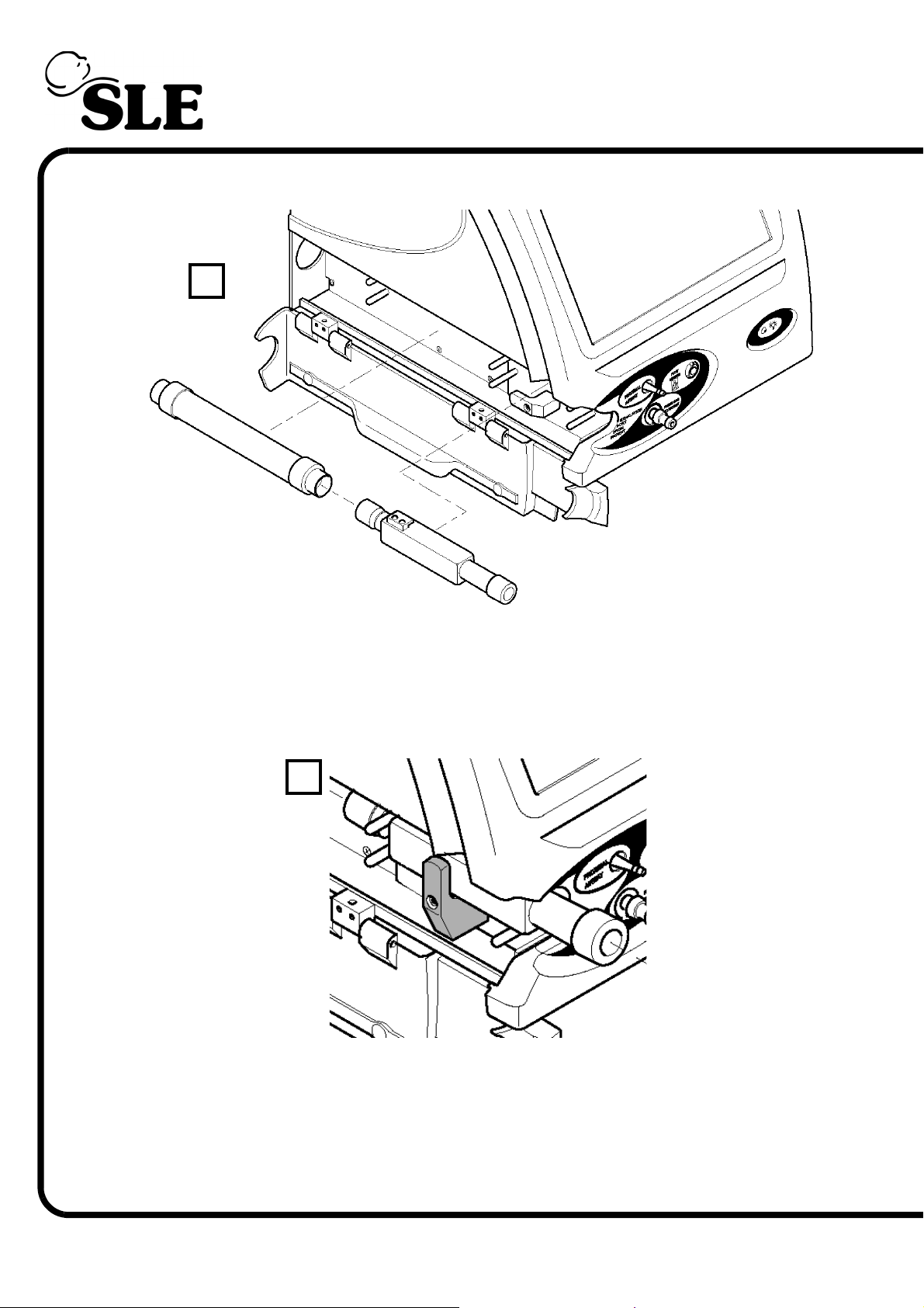
Step 5 Fit the Exhalation Block and Silencer to the Gas Manifolds
C
Connect the silencer to the exhalation block and then place the assembly onto
the gas mainfolds (C).
Lock the exhalation block by turning the clamp through 90 degrees until it is
vertical (D).
D
Close the side flap.
Page 80 of 292
Page 81
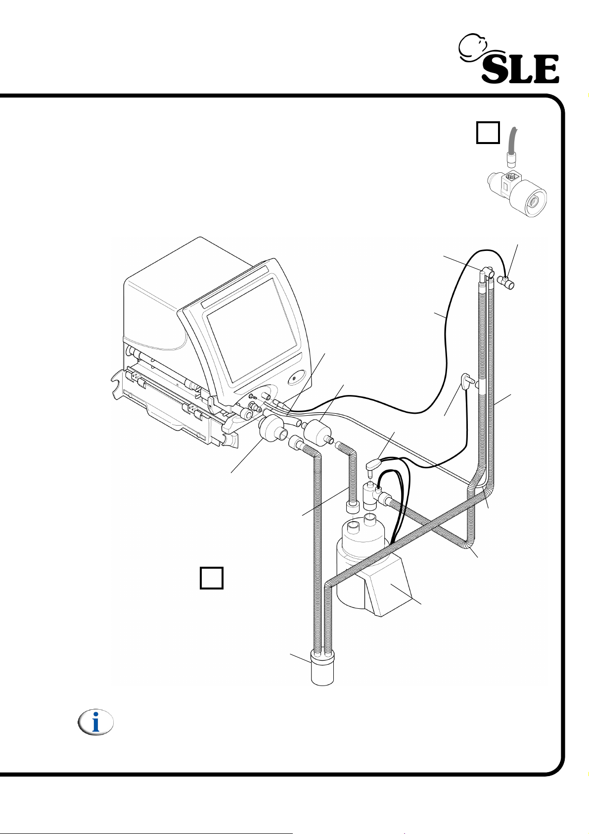
Step 6 Connect the Patient Circuit and Bacterial Filter to the Ventilator
Check that the flow sensor has been cleaned in accordance with
the manufactures instructions.
Connect the flow sensor cable to the sensor but do not fit it into
the patient circuit at this stage (E).
ET Manifold
Flow sensor Cable
Connection Tubing
Bacterial Filter
(SLE Nº:N2029)
Tem peratur e
Probes
E
Flow Sensor
Expiratory
Supply Line
Bacterial Filter
(SLE Nº:N2187)
Humidifier Supply Line
Proximal Airway
Pressure Line
Inspiratory
Supply Line
F
Humidifier
Water Trap
Connect the SLE approved patient circuit as shown in the diagram above (F).
Note: Patient circuit type and design may vary from the diagram
Fit the humidification chamber into the humidifier.
Page 81 of 292
Page 82
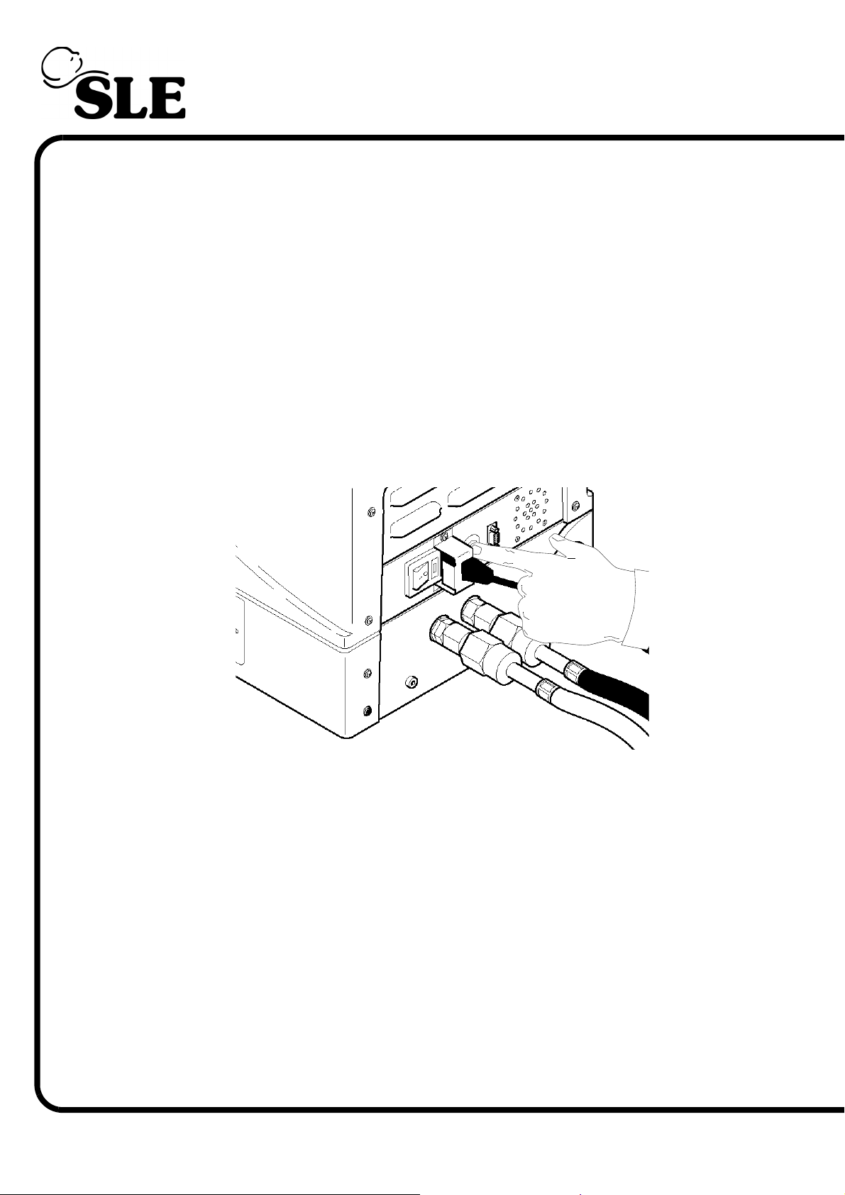
Step 7 Setup Complete
The ventilator is now ready for functional testing. Now see "Functional Testing" on
page 94.
9.2 Setup Related Items
9.2.1 Shutting Down of the Ventilator
The ventilator contains a battery back-up power supply that will continue to
operate the ventilator in the event of a power failure. The batteries take over
automatically when a power failure is experienced. The batteries also
automatically take over when the ventilator is switched Off at the rear as a safety
feature. To turn the ventilator Off when no longer required the user is required to
cut off the battery power by pressing the battery power disconnect button located
on the other side of the power cable.
Page 82 of 292
9.2.2 Back-up Battery Charging
Prior to use, the back-up batteries should be charged to allow the maximum
amount of ventilation time on backup power in the event of a mains power failure.
The ventilator should be connected to a suitable power supply, air and oxygen
gas supplies and left in Ventilation Off mode for a minimum of 24 hours.
In Ventilation Off mode set the Fi02 parameter to 21% to avoid using oxygen.
The ventilator can be left in Ventilation Off mode with no gas supplies connected,
but the user must be aware that the muted "No gas" alarm will sound continuously
during this period.
Page 83

Quick Setup Guide
Page 83 of 292
Page 84
10. Quick Setup
The alarm and functional testing in this Quick Setup section must be performed
before use on a patient.
Warning: If any of these tests do not function as described and the problem
can not be rectified by reference to the trouble shooting chapter on
page 200, then the unit should not be used until it has been repaired. Please
contact an SLE approved engineer, or SLE.
Warning: The settings used for the quick setup of the ventilator do not bear
any relation to settings for ventilation of a patient.
Warning: The ventilator must not be connected to the patient during this
procedure.
Carry out the “Ventilator Set-up” on page 78 before commencing with the
following tests.
This routine must be carried out every time the ventilator is to be used.
Page 84 of 292
Page 85
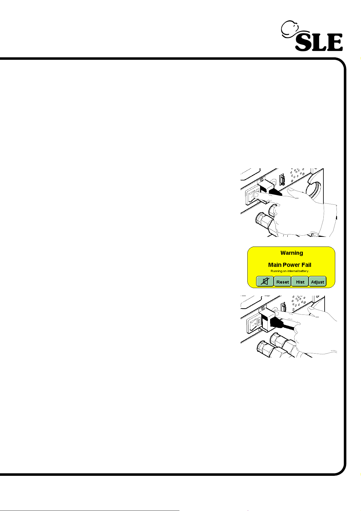
10.0.1 Complete Power Fail Alarm Test.
Step 1 The ventilator has a complete power fail alarm. This alarm is activated when both
mains power and back-up battery power fail. This alarm is a high pitched,
continuous tone emitted by the ventilator in the event of complete power failure.
Turn ON the ventilator allow the start up screen to clear and wait for it to enter the
Ventilation Off mode.
Calibrate Flow Sensor (for this calibration there is no need to occlude the flow
sensor).
Turn the ventilator OFF at the mains power switch
located on the rear of the machine.
This will trigger the mains power fail alarm.
Slowly depress the battery power termination
switch. Before the switch reaches the end of its
full travel, the audible complete power fail alarm
should be initiated. Once the alarm has been
triggered release the button, the alarm should
continue.
Re-press the battery power termination switch
fully to cancel the alarm.
Turn ON the ventilator and wait for it to enter the ventilation off mode.
Page 85 of 292
Page 86
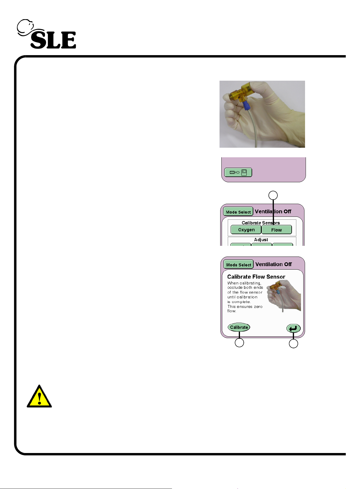
10.0.2 Calibration of the Flow Sensor
Step 2 Make sure that there is no flow passing the through
the sensor. For this purpose, occlude the flow
sensor by holding it between two fingers, closing
both ends as shown in the following picture.
Press the Options and Service Data button.
From the services panel press the Flow button (A)
With the flow sensor now occluded press the
Calibrate button (B). This initiates the calibration
cycle for the flow sensor. Keep the sensor occluded
until the words “Calibration Complete” appear
above the Calibrate button.
The sensor has now been calibrated and can be
fitted into the patient circuit.
Fit a test lung to the flow sensor.
Press the Return Button (C) twice to return to the
Ventilation Off panel or allow the panel to self
cancel after 30 seconds.
B
A
C
Page 86 of 292
Warning: If the flow sensor is incorrectly calibrated, i.e. whilst fitted to the
patient circuit or partially occluded, the user must note that the resistance
and compliance readings in the lung mechanics and measurement panel
will be incorrect. Measured values in the parameter controls will also be
incorrect and could lead a condition detrimental to the patient.
Recalibration with the sensor occluded must be carried out at all times.
Page 87
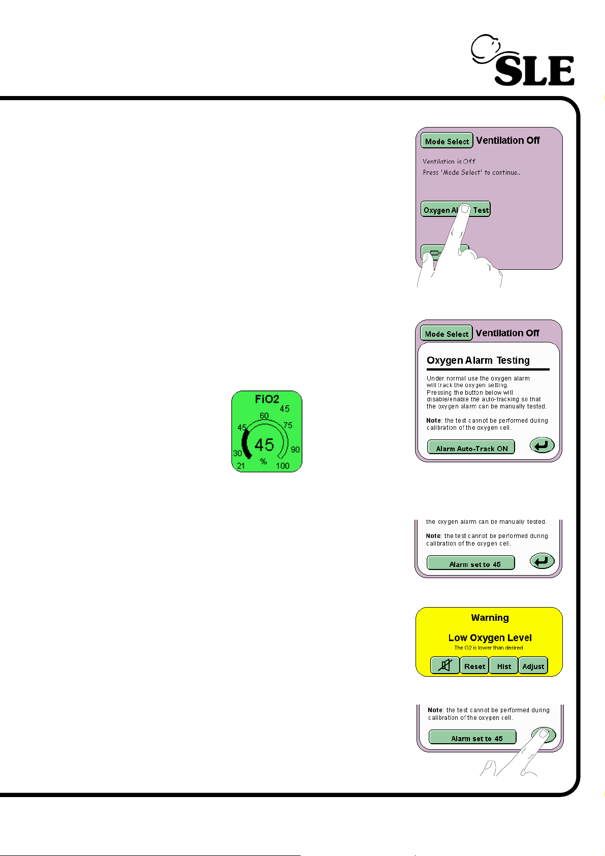
10.0.3 Low Oxygen Alarm Test Step 3 In Ventilation Off mode panel press the Oxygen
Alarm Test button.
The Oxygen alarm testing window will now be
displayed in the Mode Panel.
With the Alarm Auto-Track button set to ON set
the FiO2 parameter to 45% O2.
Once set, press the Alarm Auto-Track button. The
button will now read Alarm set to 45.
Decrease the percentage of oxygen to 37%. The
blender will reduce the percentage of oxygen to the
set value. The Low Oxygen Alarm will now be
triggered.
Further decrease the percentage of oxygen to 21%
and press the Return button to cancel the Oxygen
alarm test.
Page 87 of 292
Page 88
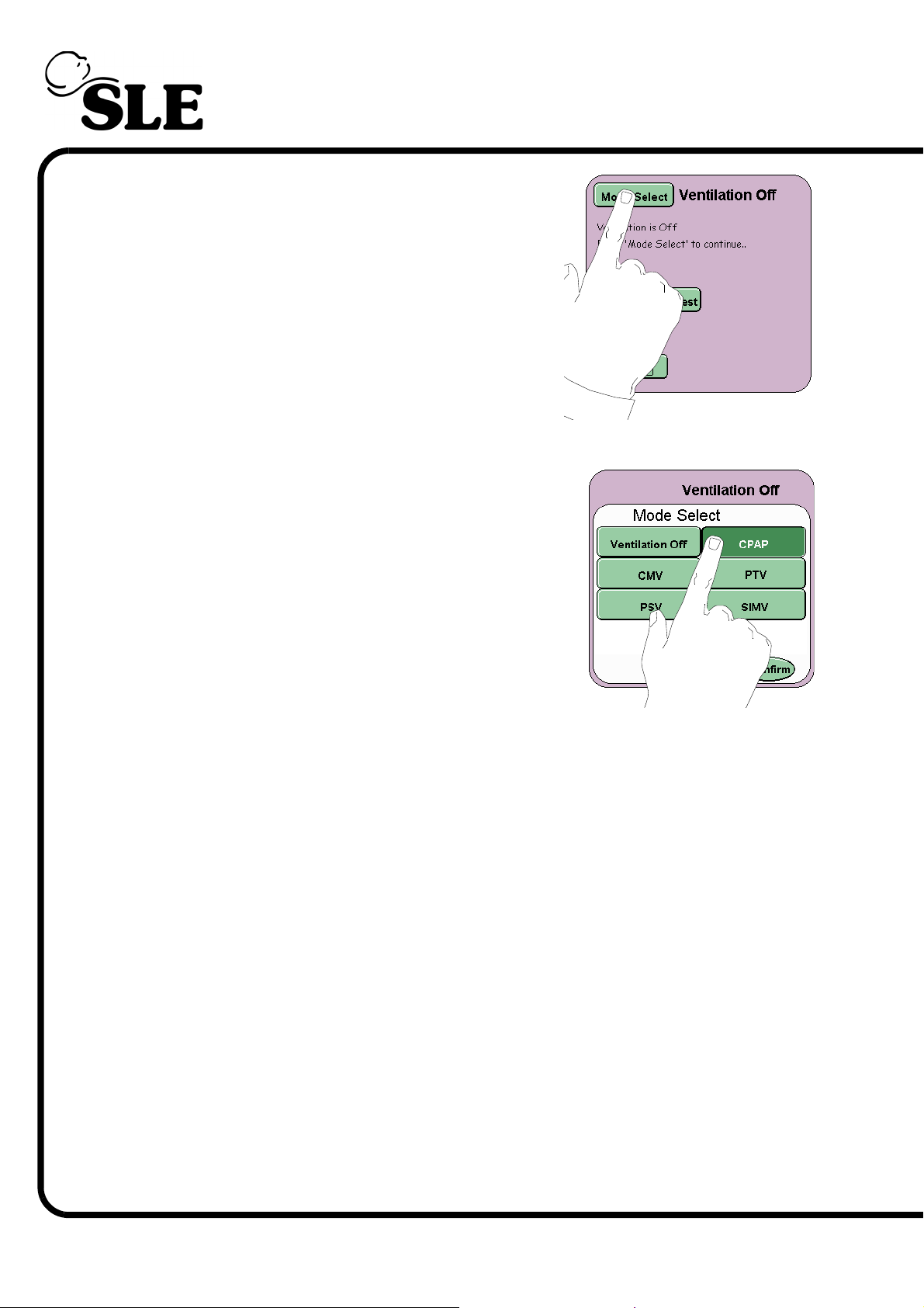
Step 4 Press the Mode Select button to enter the Mode
select panel.
Step 5 From the Mode Select panel select CPAP, press
the confirm button.
Page 88 of 292
Page 89
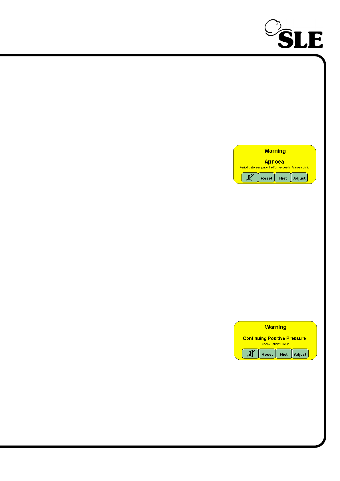
10.0.4 Apnoea Alarm
Step 6 Set the following parameters in the CPAP:
Ti.......................... 1 sec
CPAP................... 5 mbar
PIP....................... 20 mbar
FiO2..................... 21%
Verify that:
The visual and audible Apnoea alarm
is triggered after 20 seconds.
Step 7 Pull the test lung to mimic a breath, then acknowledge and reset the alarm.
Verify that:
a manual breath is delivered when the manual breath button is
pressed.
Step 8 Set the High alarm Threshold to 35mbar.
Step 9 Gently constrict the proximal airway tube so as to increase the pressure. Allow
the pressure to increase but do not allow it to exceed the High alarm threshold.
(This can be achieved by releasing the constriction of the proximal airway tube by
a small amount.)
Do not reset any Apnoea alarms that may be generated.
Verify that:
after 10 seconds the continuing
positive pressure alarm is triggered
and that the fresh gas supply is cut off.
When the gas supply is cut off release
the constriction from the proximal
airway tube.
After 6 seconds the fresh gas supply should be re-instated.
Step 10 Press the reset button in the alarm panel to clear all alarm notifications.
Page 89 of 292
Page 90
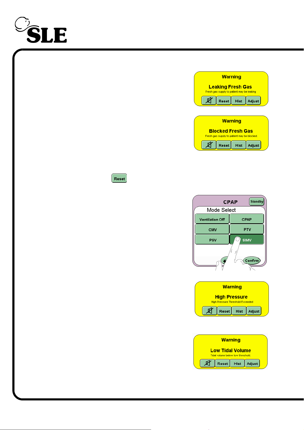
10.0.5 Leak / Block Alarm
Step 11 Disconnect the fresh gas tubing from the ventilator.
This should initiate an audible and visual LEAK
alarm indication.
Step 12 Occlude the fresh gas outlet. This should initiate an
audible and BLOCK visual alarm indication.
Reconnect the tubing, audible and visual alarms should reset.
Press the reset button to clear the alarm panel of the alarm notification.
Step 13 From the Mode Select panel select SIMV, press
the confirm button.
10.0.6 High Pressure Alarm
Lower the High Pressure Alarm threshold below the
waveform plateau. The audible and visual High
Pressure alarm should be triggered. Reset the
alarm threshold.
10.0.7 Low Tidal Volume
Raise the Low Tidal Volume alarm threshold above
the waveform plateau. The audible and visual Low
Tidal Volume alarm should be triggered. Reset the
alarm threshold.
Page 90 of 292
Page 91
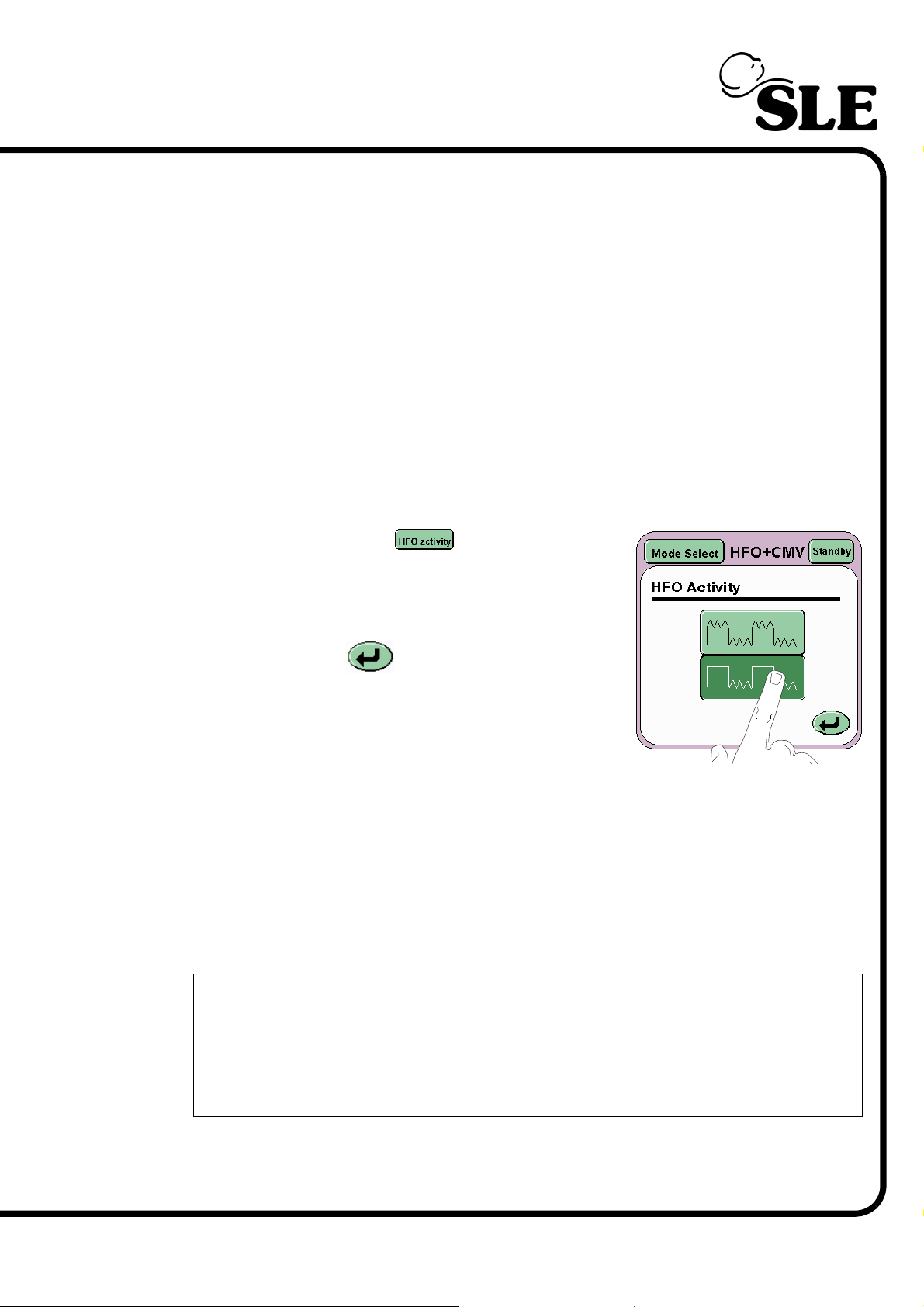
Step 14 For the SLE4000 ventilator: Select Ventilation Off from the Mode Select
panel. Press the confirm button. Advance to set Step 18
For the SLE5000 ventilator: Select HFO+CMV from the Mode Select panel, but
press the confirm button. Advance to Step 15.
10.0.8 Functional Test of HFO+CMV Mode
Set the a Delta P of 10mbar
Step 15 Verify that:
the ventilator cycles with oscillations in both the inspiratory and
expiratory phases.
the HFO waveforms appear in the waveform windows.
Step 16 Press the HFO Activity button on the Mode
panel to activate the HFO Activity Panel.
Press the Expiratory Only button.
Press the Return button.
Verify that:
the ventilator cycles with oscillations in the expiratory phase only.
Step 17 Reset the HFO activity to continuous. Select Ventilation Off from the Mode
Select panel. Press the confirm button.
Step 18 Quick Setup Complete
The ventilator is now ready for basic set-up for patient ventilation. The
ventilator should not be turned off, but remain powered up and in
Ventilation Off mode until needed.
Please read the Operational Considerations chapter on page 134 before
commencing with basic setup.
Page 91 of 292
Page 92

This page is intentionally blank.
Page 92 of 292
Page 93

Functional Testing
Page 93 of 292
Page 94
11. Functional Testing
Functional testing should be carried out at the following intervals 14 days and 30
days. At 14 days carry out a Stage 1 functional test procedure. At 30 days carry
out both Stage 1 and Stage 2 functional testing procedures.
Note: If the ventilator is in use on a patient, the user can postpone the
functional testing to a time when the ventilator is not in use.
Warning: If any of these tests do not function as described and the problem
can not be rectified by reference to the trouble shooting chapter on
page 200, then the unit should not be used until it has been repaired. Please
contact an SLE approved engineer, or SLE.
Warning: The settings used in the functional testing of the ventilator do not
bear any relation to settings for ventilation of a patient. Do not use
functional test ventilation parameters to ventilate a patient.
Warning: The ventilator must not be connected to the patient during these
procedures.
Carry out the “Ventilator Set-up” on page 78 before commencing with the
following tests.
At the end of this chapter the user will find two example check lists that can be
used to record the functional testing routines.
Page 94 of 292
Page 95
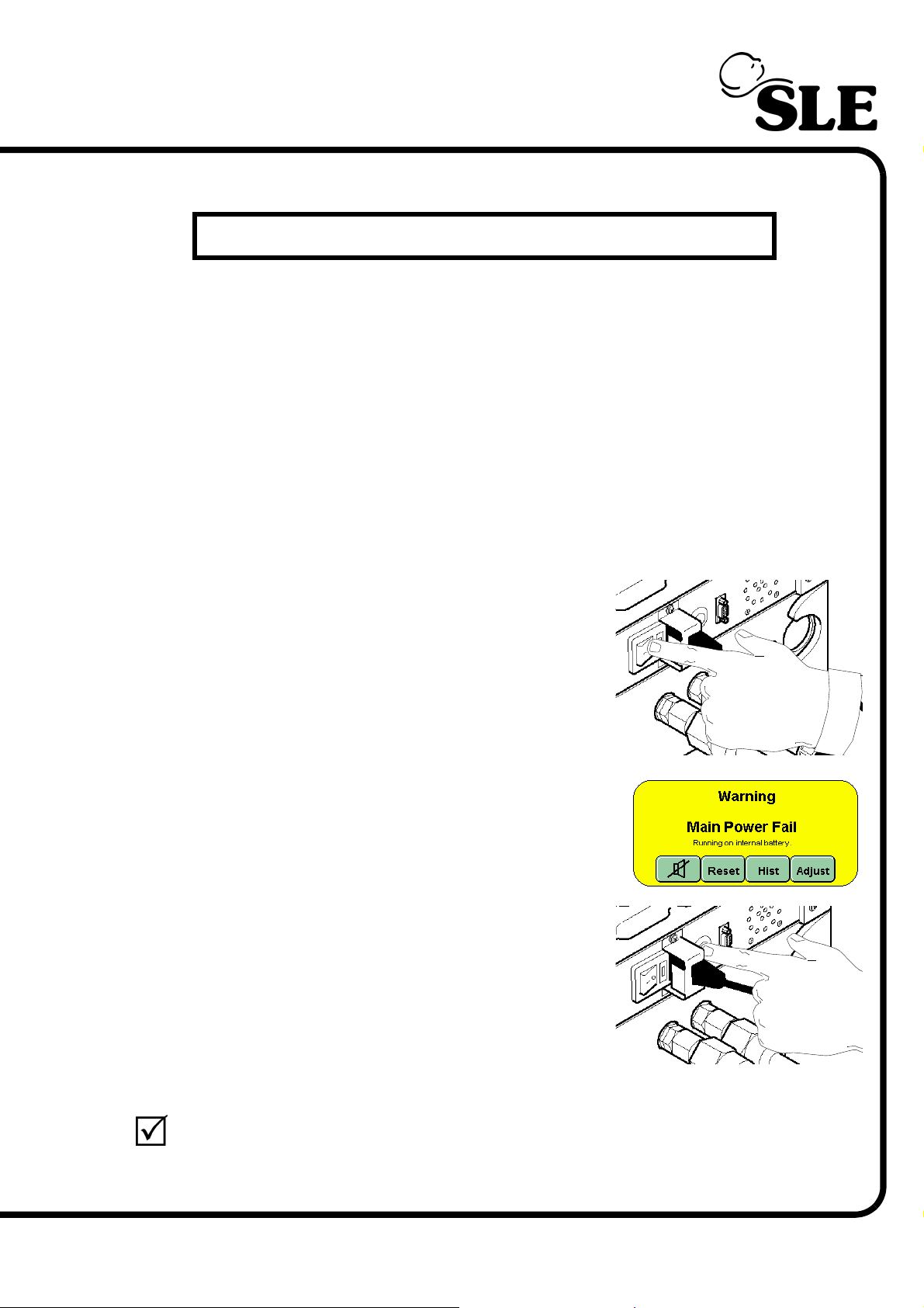
Stage 1 Functional Testing
11.1 Stage 1 Functional testing
11.1.1 Complete Power Fail Alarm Test.
Step 1 The ventilator has a complete power fail alarm. This alarm is activated when both
mains power and back-up battery power fail. This alarm is a high pitched,
continuous tone emitted by the ventilator in the event of complete power failure.
Turn ON the ventilator allow the start up screen to clear and wait for it to enter the
Ventilation Off mode.
Calibrate Flow Sensor (for this calibration there is no need to occlude the flow
sensor).
Turn the ventilator OFF at the mains power switch
located on the rear of the machine.
This will trigger the mains power fail alarm.
Slowly depress the battery power termination
switch. Before the switch reaches the end of its full
travel, the audible complete power fail alarm
should be initiated. Once the alarm has been
triggered release the button, the alarm should
continue.
Re-press the battery power termination switch
fully to cancel the alarm.
Turn ON the ventilator and wait for it to enter the ventilation off mode.
Page 95 of 292
Page 96
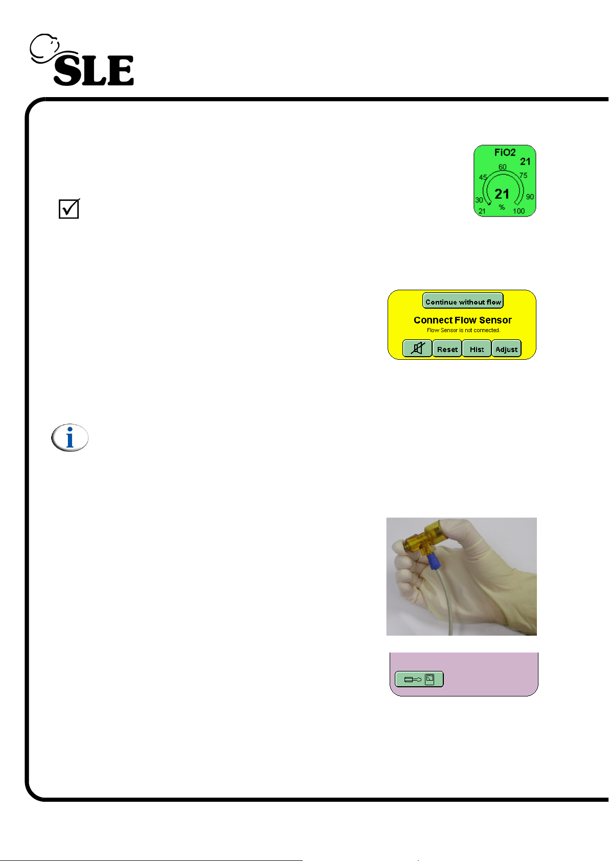
11.1.2 Setting FiO
2
Step 2 In the ventilation off mode select the FiO2 parameter and using the
arrow keys set the value to 21% FiO2. The ventilator defaults to
21% on start up.The measured value will be displayed once the O2
cell has finished it’s self calibration routine. When finished, the set
value and measured value should correspond.
11.1.3 Functional Testing with No Flow Sensor
Step 3 If the ventilator is to be used without a flow sensor
fitted then press the “continue without flow”
button in the alarm panel.
Fit a test lung to the ET manifold.
The user should now advance to section 11.1.5
Note: the functional testing routines have been written with the flow sensor
fitted. The user will be told to skip a section if it applies to testing a flow
related function.
11.1.4 Calibration of the Flow sensor
Step 4 Make sure that there is no flow passing the through
the sensor. For this purpose, occlude the flow
sensor by holding it between two fingers, closing
both ends as shown in the following picture.
Press the Options and Service Data button.
Page 96 of 292
Page 97
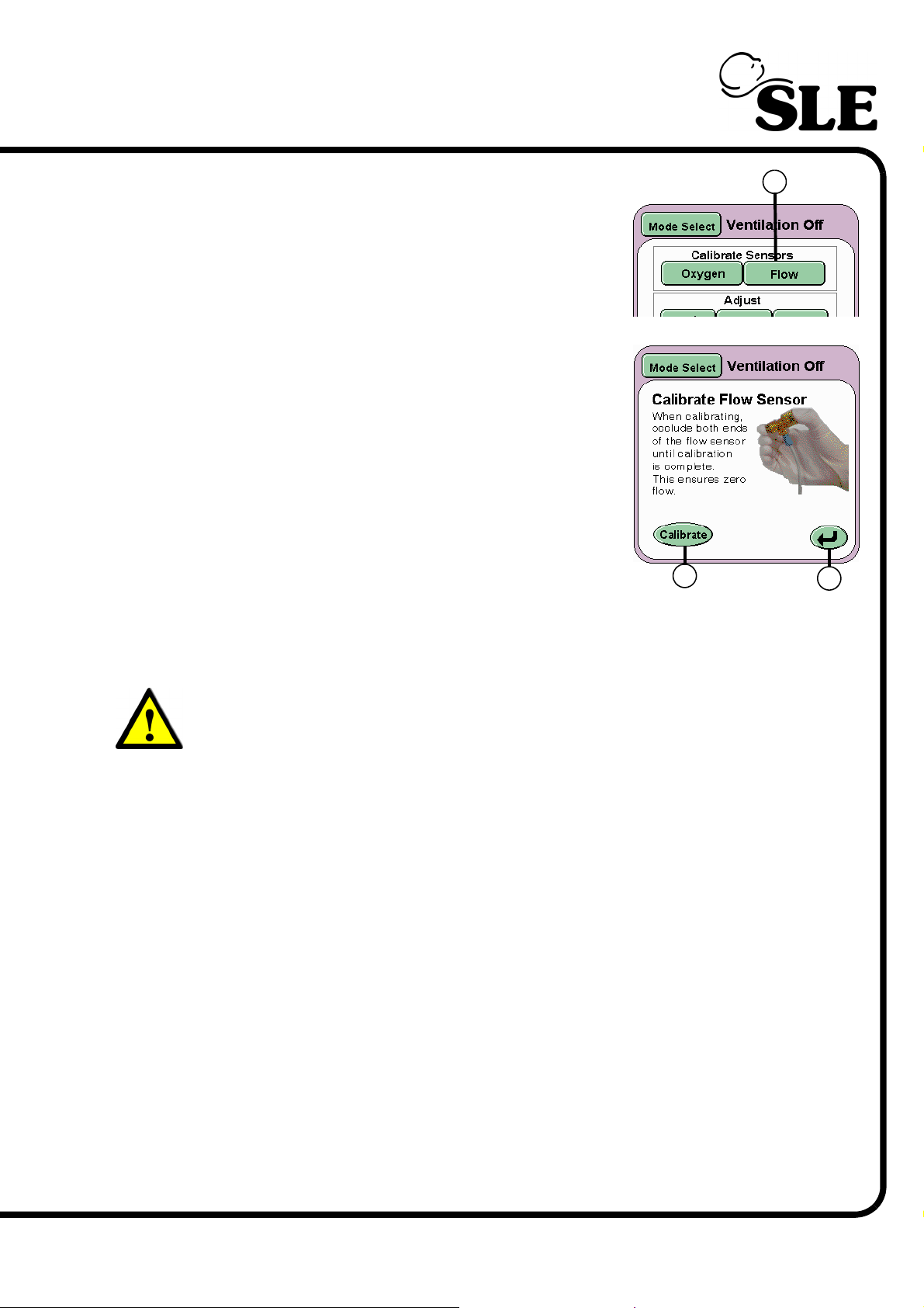
From the services panel press the Flow button (A)
With the flow sensor now occluded press the
Calibrate button (B). This initiates the calibration
cycle for the flow sensor. Keep the sensor occluded
until the words “Calibration Complete” appear
above the Calibrate button.
The sensor has now been calibrated and can be
fitted into the patient circuit.
Fit a test lung to the flow sensor.
A
Press the Return Button (C) twice to return to the
B
C
Ventilation Off panel or allow the panel to self
cancel after 30 seconds.
Warning: If the flow sensor is incorrectly calibrated, i.e. whilst fitted to the
patient circuit or partially occluded, the user must note that the resistance
and compliance readings in the lung mechanics and measurement panel
will be incorrect. Measured values in the parameter controls will also be
incorrect and could lead a condition detrimental to the patient.
Recalibration with the sensor occluded must be carried out at all times.
Page 97 of 292
Page 98
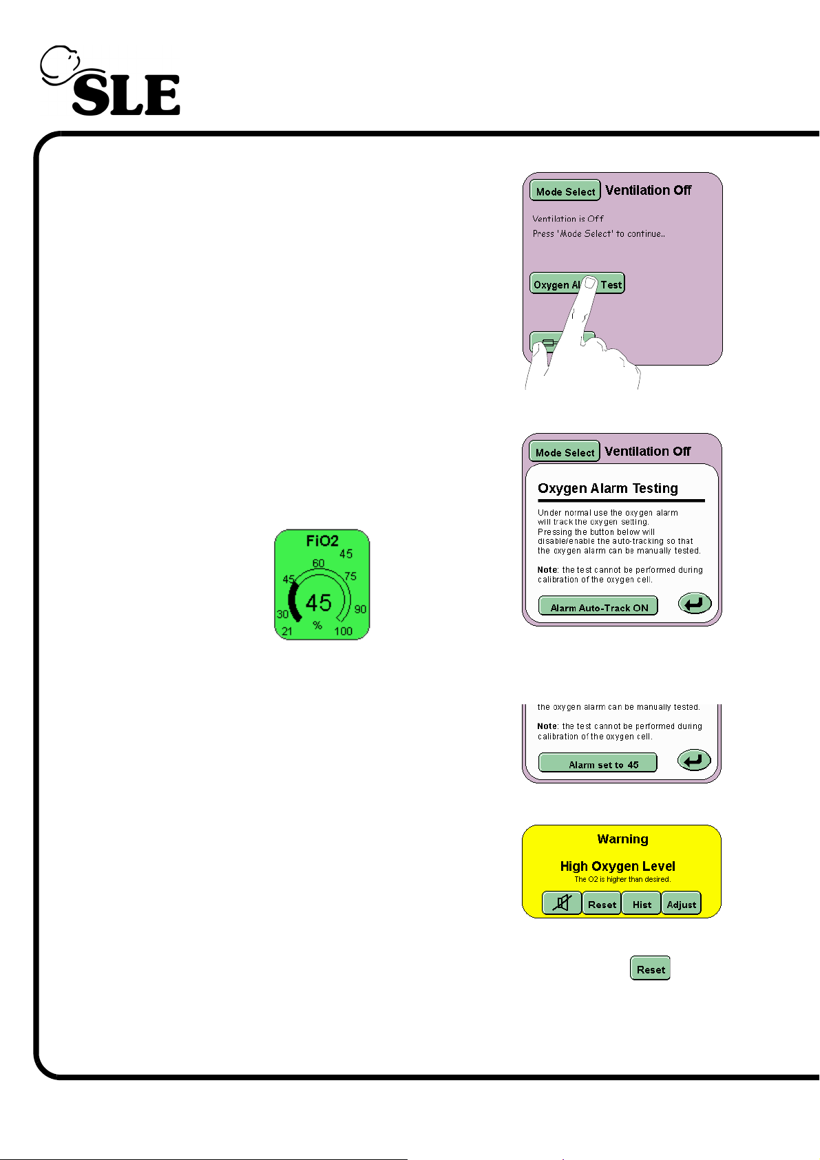
11.1.5 Oxygen Alarm Test
Step 5 In ventilation off mode panel press the Oxygen
Alarm Test button.
The Oxygen alarm testing window will now be
displayed in the Mode Panel.
With the Alarm Auto-Track button set to ON set
the FiO2 parameter to 45% O2.
Page 98 of 292
Once set, press the Alarm Auto-Track button. The
button will now read Alarm set to 45
Increase the percentage of oxygen to 53%.The
blender will increase the percentage of oxygen to
the set value. The High Oxygen Alarm will now be
triggered after one minute.
Return the percentage of oxygen to 45% and press the reset button on the
alarm panel.
Page 99
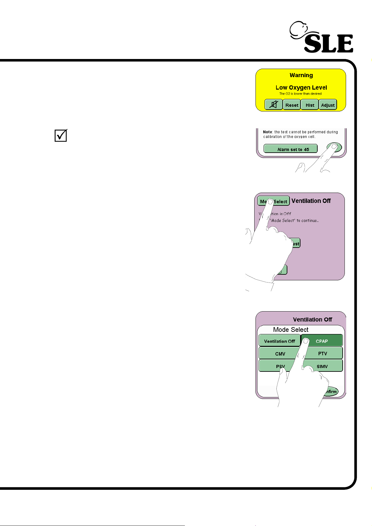
Decrease the percentage of oxygen to 37%. The
blender will reduce the percentage of oxygen to the
set value. The Low Oxygen Alarm will now be
triggered.
Further decrease the percentage of oxygen to 21%
and press the Return button to cancel the Oxygen
alarm test.
Step 6 Press the Mode Select button to enter the Mode
select panel.
Step 7 From the Mode Select panel select CPAP, but DO
NOT press the confirm button. Advance to Step 8.
Page 99 of 292
Page 100
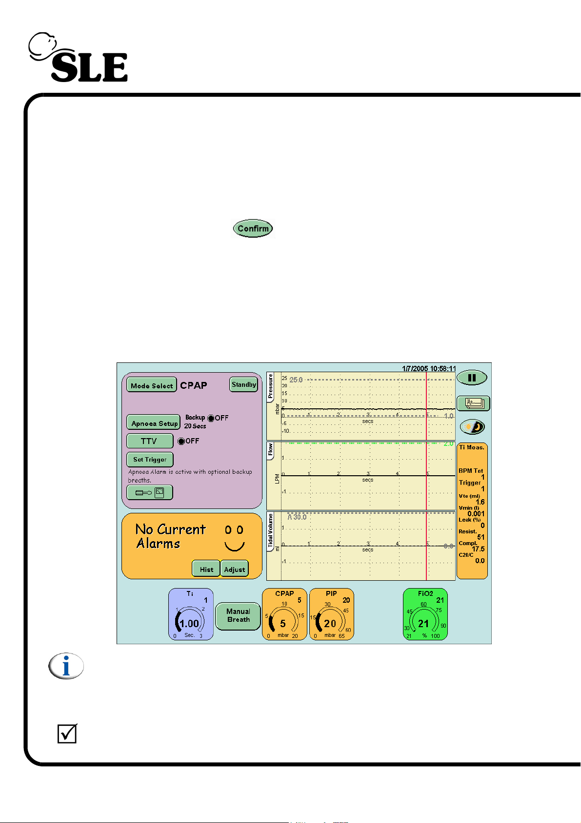
11.1.6 Function and Alarm Testing
Step 8 Set the following parameters in the CPAP preview mode:
Ti ..........................1 sec
CPAP ...................5 mbar
PIP .......................20 mbar
FiO2......................21%
After pressing the confirm button the user will be presented with the
CPAP screen.
Set the high alarm to 30 mbar
Step 9 Check that:
Apnoea Support should be set to OFF and apnoea is detected
after 20 seconds (Default value after power up).
TTV .....................is set to OFF. (This button will not appear
when functional testing with no flow sensor fitted).
Note: Press the manual breath button twice to display the measured PIP
value.
Step 10 Verify that:
Page 100 of 292
the test lung inflates.
 Loading...