

Page 1
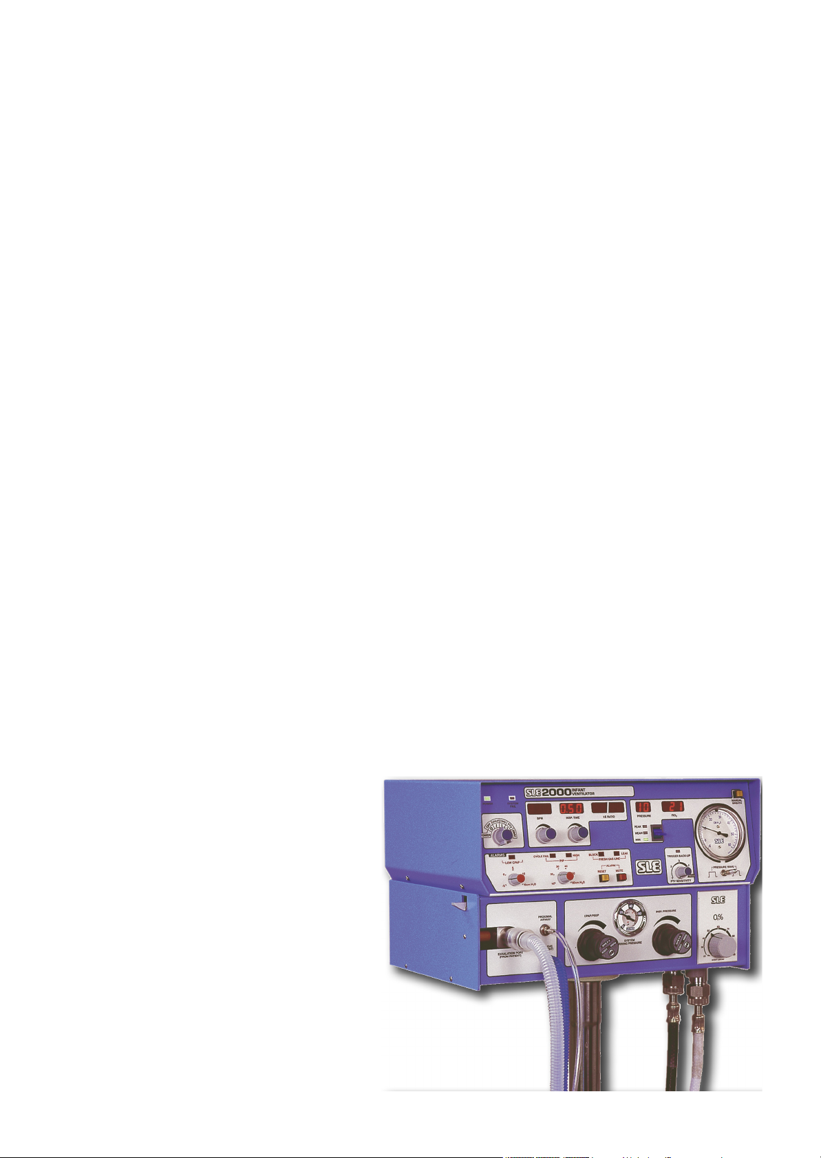
SLE2000
Service manual
Page 2

Contact Information:
SLE Limited
Twin Bridges Business Park
232 Selsdon Road
South Croydon
Surrey CR2 6PL
Telephone: +44 (0)20 8681 1414
Fax: +44 (0)20 8649 8570
E-mail: [email protected]
Web site: www.sle.co.uk
(E-mail’s should be addressed to the Service Manager)
All rights reserved. No part of this publication may be reproduced, stored in any retrieval system, or transmitted
in any form or by any means, electronic, mechanical, photocopy, recording or otherwise, without prior
permission of SLE. © Copyright SLE 19/03/2012.
Manual : SM7 Issue 12
SLE Part Nº: N2000/00
Page 2 (SLE2000)
Page 3

Contents
1. Introduction ............................................................................................................... 8
2. Principles of operation SLE2000 valveless system ................................................... 8
3. User/owner responsibility .......................................................................................... 10
4. Warnings ................................................................................................................... 11
5. Symbols used on or in the equipment ....................................................................... 12
6. Glossary of abbreviations ......................................................................................... 13
7. Ventilator control description ..................................................................................... 16
7.1. Front Panel..................................................................................................... 16
7.2. Function of front panel controls and indicators............................................... 17
7.3. Rear panel...................................................................................................... 19
7.4. Side panel ...................................................................................................... 20
8. Accessing the SLE2000 internal components. ......................................................... 22
8.1. Electronic module........................................................................................... 22
8.2. Pneumatic module.......................................................................................... 22
8.2.1. To Remove the A0702/01 PCB (Runner mounted) ................................. 23
8.2.2. To Remove the A0702/01 PCB (Pillar mounted) ..................................... 24
8.3. To Separate The Two Modules ...................................................................... 25
8.4. Removal Of The Oxygen Blender................................................................... 26
8.5. Removal of the Oxygen cell............................................................................ 27
8.5.1. Oxygen Cell Mounting ............................................................................. 27
9. Maintenance ............................................................................................................. 30
9.1. Cleaning, disinfection and sterilization ........................................................... 30
9.1.1. Preparation of a new ventilator ................................................................ 30
9.1.2. Cleaning and disinfection of an in-service ventilator................................ 30
9.1.3. Cleaning, Disinfection & Sterilization chart .............................................. 31
9.1.4. Cleaning method...................................................................................... 31
9.1.5. Disinfection method ................................................................................. 32
9.1.6. Sterilization method ................................................................................. 32
9.2. Filter systems ................................................................................................. 33
9.2.1. Bacterial filter, SLE Part Nº:N2029 (Autoclavable) .................................. 33
9.3. Bacterial filter, SLE Part Nº:N2587 (Single use)............................................. 33
9.3.1. Precautions when using bacterial filter N2587......................................... 33
9.4. Monthly operational checks............................................................................ 34
9.4.1. Battery condition and LED display test. ................................................... 34
9.4.2. Air and oxygen supply failure alarm test.................................................. 34
9.4.3. Condition of O2 cell.................................................................................. 34
9.4.4. Proximal airway pressure gauge accuracy .............................................. 34
9.4.5. Inspiratory nozzle..................................................................................... 34
9.5. Preventative maintenance.............................................................................. 35
9.6. Overhaul......................................................................................................... 35
9.6.1. Service parts list ...................................................................................... 36
(SLE2000) Page 3
Page 4

10. Electronic module description .................................................................................38
10.1. Description of operation ................................................................................38
11. Pneumatic module description ...............................................................................40
11.1. Description of operation ................................................................................40
11.2. Fresh Gas System ........................................................................................42
11.3. CPAP System ...............................................................................................43
11.4. Inspiratory System ........................................................................................44
11.5. Pneumatic Circuit Diagram ...........................................................................45
11.6. Pneumatic Module Parts List ........................................................................46
12. Test Equipment Required ........................................................................................50
13. SLE2000 Calibration Procedure ..............................................................................51
13.1. Electronic unit preliminary checks and adjustment .......................................51
13.1.1. System Watchdog ..................................................................................52
13.1.2. Pressure Transducer, PTR1 Calibration. ...............................................52
13.1.3. Pressure Transducer Buffered Output ...................................................52
13.1.4. CPAP alarm threshold control. ...............................................................52
13.1.5. PIP alarm threshold control. ...................................................................53
13.1.6. Inspiration Time Control .........................................................................53
13.1.7. Alarm Volume Control ............................................................................53
13.1.8. Airway Trigger Calibration (Part 1) .........................................................53
13.2. Pneumatic module setup and calibration ......................................................54
13.2.1. Fresh Gas Pressure Regulator (REG3) Adjustment ..............................54
13.2.1. Minimum blender flow needle valve (NV2) adjustment .........................54
13.2.2. Fresh gas flow needle valve (NV1) adjustment......................................54
13.2.3. Fresh Gas Block and Leak Alarm...........................................................55
13.2.4. FiO2 Digital Display................................................................................55
13.2.5. Airway Trigger Calibration (Part 2) ........................................................56
13.3. Soak Test......................................................................................................57
13.4. CMV mode soak test 50 hours .....................................................................57
13.5. Functional testing (Post soak).......................................................................58
13.5.1. Perform Electrical Safety Test................................................................58
4.0.1. Basic Operation........................................................................................58
4.0.2. Mains Voltage tolerance test. ...................................................................60
4.1. SLE 2000 Electrical Troubleshooting Chart ....................................................62
4.2. SLE 2000 Pneumatic Troubleshooting Chart..................................................63
5. Technical Specification ..............................................................................................66
5.1. Conventional Ventilation .................................................................................66
5.2. Displays ..........................................................................................................66
5.3. Controls...........................................................................................................67
5.4. Alarms.............................................................................................................67
5.5. Power , Dimensions etc. .................................................................................68
6. Electronic Circuit Details ...........................................................................................70
6.1. Display Board A0700/01 .................................................................................70
6.1.1. Display Board Circuit Diagram A0700/01.................................................71
Page 4 (SLE2000)
Page 5

6.2. LED Board A0701/01 ..................................................................................... 73
6.2.1. LED Circuit Board Diagram CD/A0701/01............................................... 74
6.3. Ventilator CPU Board AS/A0702/01 Issue 4 ................................................. 77
6.3.1. Ventilator CPU Board CD/A0702/01 Issue 2 Sheet 1 of 3....................... 78
6.3.2. Airway Trigger Circuit Diagram CD/A0702/01 Sheet 2 of 3..................... 79
6.3.3. Window Pressure Alarm A0702/01 Sheet 3 of 3 ..................................... 80
6.4. Ventilator CPU Board AS/A0702/01 Issue 5 ................................................. 84
6.4.1. Ventilator CPU Board CD/A0702/01 Issue 6 ........................................... 85
6.5. Ventilator CPU Board AS/A0702/01 Issue 5 ................................................. 89
6.5.1. Ventilator CPU Board (Detail A) .............................................................. 90
6.5.2. Ventilator CPU Board CD/A0702/01 Issue 7 ........................................... 91
6.6. RS232/423 Option.......................................................................................... 96
6.7. PSU PCB AS/A0703/01 issue 3 ..................................................................... 99
6.7.1. Power Supply Circuit Diagram CD/A0703/01 issue 4.............................. 100
6.8. PSU PCB AS/A0703/01 issue 7 ..................................................................... 103
6.8.1. Power Supply Circuit Diagram CD/A0703/01 issue 5.............................. 104
6.9. PSU PCB AS/A0703/01 issue 8 ..................................................................... 107
6.9.1. Power Supply Circuit Diagram CD/A0703/01 issue 6.............................. 108
6.10. Back-up alarm sounder AS/A0703/03 issue 1.............................................. 111
6.10.1. Back-up alarm sounder circuit diagram CD/A0703/03 issue 1 .............. 112
6.11. A0704 P.S.U. PCB assembly ....................................................................... 114
6.12. CD/W0288 Wireloom issue 1 ....................................................................... 117
6.13. CD/W0288 Wireloom issue 3 ....................................................................... 118
6.14. Electronic Chassis Stage 1 AS/L0105 issue 8 ............................................. 120
6.15. Electronic Chassis Stage 2 AS/L0104 issue 4 ............................................. 125
6.15.1. Electronic Chassis AS/L0104 issue 4 .................................................... 126
6.16. Electronic Chassis Stage 2 AS/L0104 issue 8 ............................................. 129
6.16.1. Electronic Chassis AS/L0104 issue 8 .................................................... 130
6.17. Electronic Chassis Stage 1 AS/L0105 issue 9 ............................................. 133
6.18. Electronic Chassis Stage 2 AS/L0104 issue 9 ............................................. 138
6.18.1. Electronic Chassis AS/L0104 issue 9 .................................................... 139
7. Service Information and Technical bulletins ............................................................. 156
7.1. Service Information ........................................................................................ 157
7.1.1. SI 980301 Ventilator Alarms &INOSYS Nitric Oxide Delivery System .... 157
7.1.2. SI 980302 Ventilator oxygen cells (N2191) ............................................. 159
7.1.3. SI 990302 Possible inadvertant solenoid failure messages .................... 160
7.1.4. SI 000201 Leak Alarm Trigger Threshold................................................ 162
7.1.5. SI 020901 Cleaning, Disinfection and Sterilisation of SLE ventilators..... 164
7.1.6. SI 031101 N2183 0-4 bar pressure gauge .............................................. 165
7.1.7. SI 050301Maximum Mean & Min Pressure Selection Switch.................. 166
7.1.8. SI 050701 Activation of watchdog secondary alarm sounder in case of
primary alarm sounder failure. ............................................................................ 167
7.1.9. SI 060104 Replacement N2125 push button switches ............................ 168
7.1.10. SI 060201 New PCB mounting method ................................................. 170
7.1.11. SI 060301 O0408 key switch replacement ............................................ 171
7.1.12. SI 070301 Design and component change to the A0703/01 PSU PCB 173
(SLE2000) Page 5
Page 6

7.2. Technical Bulletins ..........................................................................................174
7.2.1. TB 990603 Removal of hour counter from electrical chassis. ..................174
7.2.2. TB 000201 New versions of control software...........................................175
7.2.3. TB 000801 Ventilator Firmware Status ....................................................176
7.2.4. TB 040301 SLE2000 CPU Boards ...........................................................179
7.2.5. TB 040401 V0226 Potentiometer .............................................................181
7.2.6. TB060901 Alarm sounder replacement at 10,000 hr overhaul.................182
6. Issue Revision Record ..............................................................................................185
7. Index ..........................................................................................................................186
Page 6 (SLE2000)
Page 7

Introduction
(SLE2000) Page 7
Page 8

1. Introduction
The SLE2000 is a constant flow, time cycle, and pressure limited neonatal ventilator with
patient triggering.
Main features are that it has no expiratory valve but uses a reverse flow of mixed gas that is
injected from the exhaust manifold into the expiratory limb of the patient circuit. This flow of
gas has the effect of compressing 5 LPM humidified gas into the patient ET tube.
The advantage of this system is that there is no expiratory resistance due to valves or
diaphragms, therefore no inadvertent PEEP is generated.
2. Principles of operation SLE2000 valveless system*
The patient circuit is supplied with a constant fixed flow of 5LPM fresh gas. This gas comes
from the internally mounted oxygen blender and its concentration is also monitored by a fuel
cell and displayed on the FlO2 digital display. This fresh gas supply is then passed through a
humidifier to the inspiratory port of the patient ET connector. Built into the ventilator are
circuits to detect either a gas flow failure or a tubing blockage. The patient circuit requires a
restrictor fitted into the inspiritory port. Therefore, only SLE approved patient circuits must
be used.
The Expiratory limb of the patient circuit is connected to the Exhalation port on the ventilator.
This consists of a removable block mounted on a manifold, accessed by lowering the left
hand side cover. The expiratory manifold has two nozzles. The front one to generate CPAP/
PEEP and is supplied via the CPAP regulator on the front panel of the Pneumatic Module.
The rear one to generate peak inspiratory pressure(PIP).
To avoid the possibility of gas dilution these regulators are supplied with the same oxygen
concentration as the Fresh Gas supply . The front nozzle is used to generate an opposing
flow to the Fresh Gas in the exhalation block and thus create CPAP The rear nozzle is used
to generate the peak inspiratory pressure in the same way, supplying constant pressures at
all breathing rates.
Page 8 (SLE2000)
Page 9
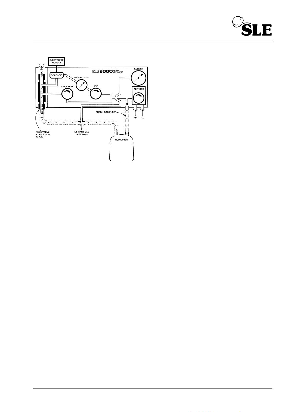
The PIP regulator and gauge on the front
panel set the pressure that is supplied to a
solenoid valve which is connected to the rear
nozzle.
The Electronic Module controls the rate and
duration of the flow of Driving Gas into the
Exhalation block in opposition to the Fresh
Gas flow. This opposing flow acts as a
pneumatic piston and creates a pressure
wave at the ET manifold. The lung inflation
pressure and hence the tidal volume are
controlled by the PIP regulator.
NOTE: The ventilator should be set to a
square waveform for breathing rates above 60 BPM
* The Valveless Ventilation Principle was designed and patented by Prof. J G Whitwam and Mr. M. K.
Chakrabarti of the R.P.G.M.S Hammersmith Hospital.
This patent is exclusively licensed to SLE
(SLE2000) Page 9
Page 10

3. User/owner responsibility
This SLE 2000 INFANT VENTILATOR equipment and the authorised accessories for it are
designed to function as specified in the relevant instruction manual only when operated,
maintained and repaired in accordance with supplied manuals and instructions. This
equipment must be periodically checked, recalibrated, maintained and components repaired
and replaced when necessary for the equipment to operate safely and reliably. Parts that
have failed, in whole or in part, or exhibit excessive wear, or are contaminated, or are
otherwise at the end of their useful life should not be used and should be replaced
immediately with parts supplied by SLE or parts which are otherwise approved by SLE.
Equipment which is not functioning correctly or is otherwise in need of repair or maintenance
must not be used until all necessary repairs and/or maintenance have been completed and
a factory authorised service representative has certified that the equipment is fit and ready
for use. This equipment and any of its accessories or component parts should not be
modified.
The owner/user of this equipment shall have the sole responsibility and liability for any
damage or injury to persons or property (including the equipment itself) resulting from
operation not in accordance with the operating instructions, or from faulty maintenance not
in accordance with the authorised maintenance instructions, or from repair by anyone other
than a factory authorised service representative, or from unauthorised modification of the
equipment or accessories, or from the use of components or accessories that have either
been damaged or not authorised for use with this equipment by the factory.
Page 10 (SLE2000)
Page 11

4. Warnings
1 Oxygen - Clinical use. Oxygen is a drug and should be prescribed as such.
2 Oxygen - Fire Hazard. Oxygen vigorously supports combustion and its use requires
special precaution to avoid fire hazards. Keep all sources of ignition away when
oxygen is in use. Do Not use oil or grease on oxygen fittings or where oxygen is used.
3 The ventilator functional tests must be carried out each time the SLE 2000 is used on
patients. If any of these tests do not function as described then there is a problem and
the ventilator must not be used until it is rectified.
4 The humidifier used in the patient circuit must be operated and maintained in
accordance with its manufacturer’s instructions. It is the owners responsibility to
ensure that the equipment is regularly maintained.
5 Failure to comply with the recommended service programs could lead to injury to the
patient, operator or damage to the ventilator. It is the owners responsibility to ensure
that the equipment is regularly maintained.
6 Functioning of this ventilator may be adversely affected by high frequency surgical
(Diathermy) , defibrillators, mobile phones, short-wave therapy or equipment producing
strong magnetic fields, operating the in vicinity.
7 The Ventilator must be plugged into a suitably rated and grounded electrical power
source.
8 There is no special protection provided against ingress of water or liquids.
9 The equipment is not suitable for use with, or in the presence of flammable anaesthetic
mixtures.
10 Use only SLE approved patient circuits. On no account should antistatic or electrically
conductive tubing be used in the patient circuit.
11 No external voltage should be applied to the auxiliary socket. Any connections to this
socket must be approved by SLE and screened to comply with EMC regulations.
Ensure protection cap is fitted when socket is not in use.
12 The electronic module of the ventilator contains a primary battery for mains failure
alarm, if the ventilator is not to be used for 3 months or more, then the battery should
be removed.
13 Care should be taken when attaching other equipment as this may affect stability.
14 If the SLE 2000 Infant Ventilator is adversely affected by equipment emitting
electromagnetic interference then that equipment should be switched off or removed
from the vicinity of the 2000. Conversely, if the 2000 is the source of such interference
to neighbouring equipment then it should be switched off or taken to another location.
(SLE2000) Page 11
Page 12
5. Symbols used on or in the equipment
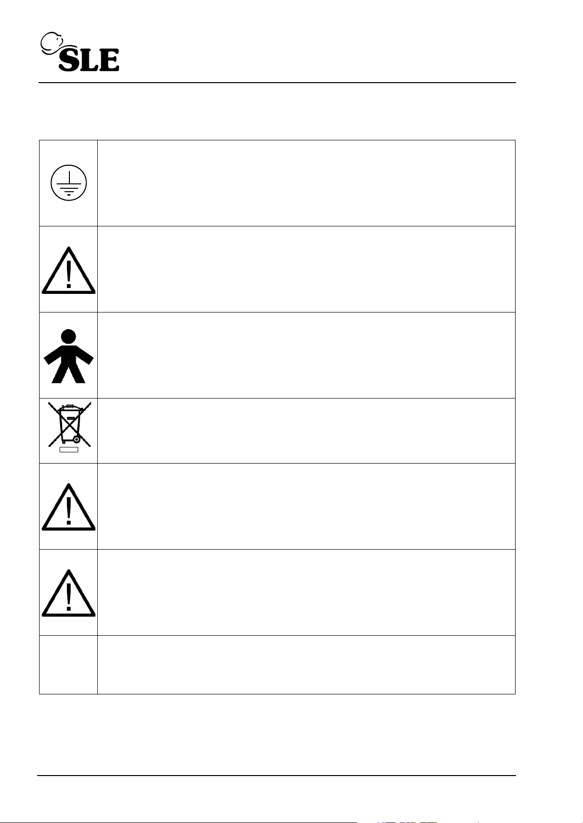
Protective Earth
Attention, Consult accompanying documents.
B.S.I. and I.E.C. symbol for equipment with type B (non isolated parts).
Mains
Fuses
Do not dispose of as general waste (WEEE directive).
(Appears on serial number label).
WARNING : - No external voltage should be applied to the auxiliary socket.
WARNING : - The electronic module contains a primary battery. If the unit is
not to be used for a period exceeding 3 months, it is recommended that the
battery be removed.
Two externally accessible fuses are;
Type T 0.2 amps. For 200 - 250V
Type T 0.5 amps. For 100 - 120V
Page 12 (SLE2000)
Page 13

6. Glossary of abbreviations
amp........................ Ampere
BPM ....................... Breaths Per Minute
cm .......................... Centimetre
cmH2O ................... Centimetres of Water Pressure
CMV ....................... Continuous Mandatory Ventilation
CPAP ..................... Continuous Positive Airway Pressure
°C........................... Degrees Centigrade
°F ........................... Degrees Fahrenheit
DISS....................... Diameter Index Safety System
ETO........................ Ethylene Oxide
ET .......................... Endotracheal
Exp......................... Expiration Time
FIO2....................... Fractional concentration of Inspired Oxygen
Hz........................... Hertz
ID ........................... Internal Diameter
I:E........................... Inspiratory : Expiratory ratio
Insp ........................ Inspiration Time
IMV......................... Intermittent Mandatory Ventilation
MAP ....................... Mean Airway Pressure
IPPB....................... Intermittent Positive Pressure Breathing
IPPV....................... Intermittent Positive Pressure Ventilation
kg ........................... Kilogram
lb ............................ Pound
LPM........................ Litres per Minute
Peak....................... Peak Airway Pressure
ml ........................... Millilitre
O2........................... Oxygen
PEEP ..................... Positive End Expiratory Pressure
PSI ......................... Pounds per Squire Inch
psig ........................ Pounds per Squire Inch Gauge
SIMV ...................... Synchronous Intermittent Mandatory Ventilation
VAC........................ Volts, Alternating Current
Vt............................ Tidal Volume
Nist......................... Non interchangable Standard Terminal
PTV ........................ Patient Triggered Ventilation
PIP ......................... Peak Inspiratory Pressure
ms .......................... Millisecond
(SLE2000) Page 13
Page 14

This page is intentionally blank.
Page 14 (SLE2000)
Page 15

Ventilator Control Description
(SLE2000) Page 15
Page 16
7. Ventilator control description
Electronic
Module
Pneumatic
Module
28
1
2
3
4
5
7
9
12
13
14
17
18
19
20
21
22
24
25
26
10
27
6
8
11
15
23
16
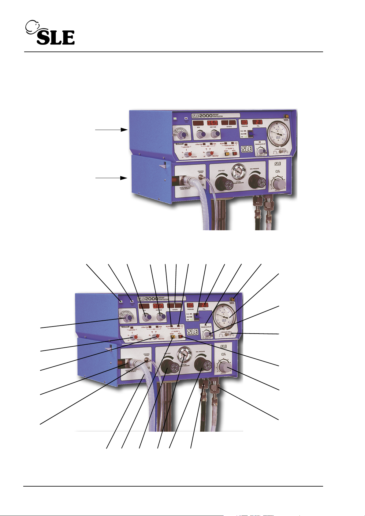
The SLE 2000 consists of two linked modules, Electronic and Pneumatic.
7.1 Front Panel
Page 16 (SLE2000)
Page 17

7.2 Function of front panel controls and indicators
Nº Item Description
1 POWER and
OPERATIONAL
Selects Power OFF, ALARM TEST/CPAP, CMV,
PTV, SIMV modes.
MODE Switch
2 POWER LED Indicates power is ‘ON’.
3 SYSTEM FAIL LED When this LED lights and the alarm sounds, it
indicates failure of the main processor. If this
happens, the ventilator must be removed from
service.
4 BPM digital display
with adjustment
knob
5INSP. TIME digital
display with
adjustment knob
6 FRESH GAS
Displays between 1-250 BPM.
Available in two ranges: 1-125 BPM& 126-250
BPM, selectable by rear security key switch
Inspiratory Time
Displays 0.1-3.0 seconds in 1-125 BPM range
or 0.01-0.3 seconds in 126-250 BPM range.
Indicates problems within the patient circuit line.
BLOCK audible
alarm.
7 I:E RATIO digital
display
Displays from 9.9:1 to 1:9.9 calculated from BPM
and insp. time
8 LEAK LED’s
Indicates problems within the patient circuit line.
audible alarm.
9 MAX MEAN MIN
switch with digital
Selects and displays Max., Mean or Min airway
pressures.
PRESSURE display
10 FIO2 digital display Accurately displays the % O2 as set by the Air-
Oxygen Blender.
11 TRIGGER BACK-
UP LED
Indicates a machine-delivered breath due to patient
failure to trigger ventilate or during back-up time
window.
12 MANUAL BREATH
Pushbutton
Causes delivery of a single breath in CPAP, CMV
and PTV modes to preset inspiration times and
pressures.
13 Pressure Gauge -6
to +60 cmH2O.
Proximal Airway Pressure. This pressure is
displayed more accurately by the independent
digital display.
14 PTV SENSITIVITY
control
Variable patient trigger level setting.
Sensitivity between 1(least sensitive to patient
effort) and 5 (most sensitive to patient effort).
(SLE2000) Page 17
Page 18

Nº Item Description
15 PRESSURE WAVE
switch
16 ALARM MUTE
Permits change of leading edge of pressure wave
from square to taper in 1-125 BPM range only.
Mutes audible alarms for one minute.
Pushbutton and
LED
17 AIR OXYGEN
BLENDER control
Sets air/oxygen mix between 21 and 100% 02 ±
3%
with digital indication from independent monitoring
circuits.
18 O2 inlet O2 hose connector.
19 Medical air inlet Medical air hose connector.
20 Inspiratory
Pressure
Regulator
21 SYSTEM DRIVING
PRESSURE gauge
Adjusts driving pressure to set circuit inspiratory
pressure.
Range 0-60 cmH2O.
Approximate indication of the pressure above
PEEP which will be delivered to the patient in CMV,
PTV, SIMV or manual breath modes.
22 CPAP/PEEP
regulator
Sets CPAP level in the circuit, range is 0 to 15
cmH2O (nominal).
23 ALARM RESET
Resets audible and visual alarms.
Pushbutton
24 Fresh Gas Port 5LPM blended gas supply to patient (ventilator
powered up).
1LPM blended gas supply to patient (ventilator
OFF)
25 Proximal airway Proximal airway tube connector.
26 Exhalation block Connection for expiratory limb of patient circuit.
27 PIP, CYCLE FAIL
and HIGH alarm
Sets visual and audible alarm level for inspiratory
pressure between 0 and 60 cmH2O.
LED’s with control
28 CPAP Alarm LED
and control
Sets visual and audible alarm level for CPAP
pressure.
Page 18 (SLE2000)
Page 19
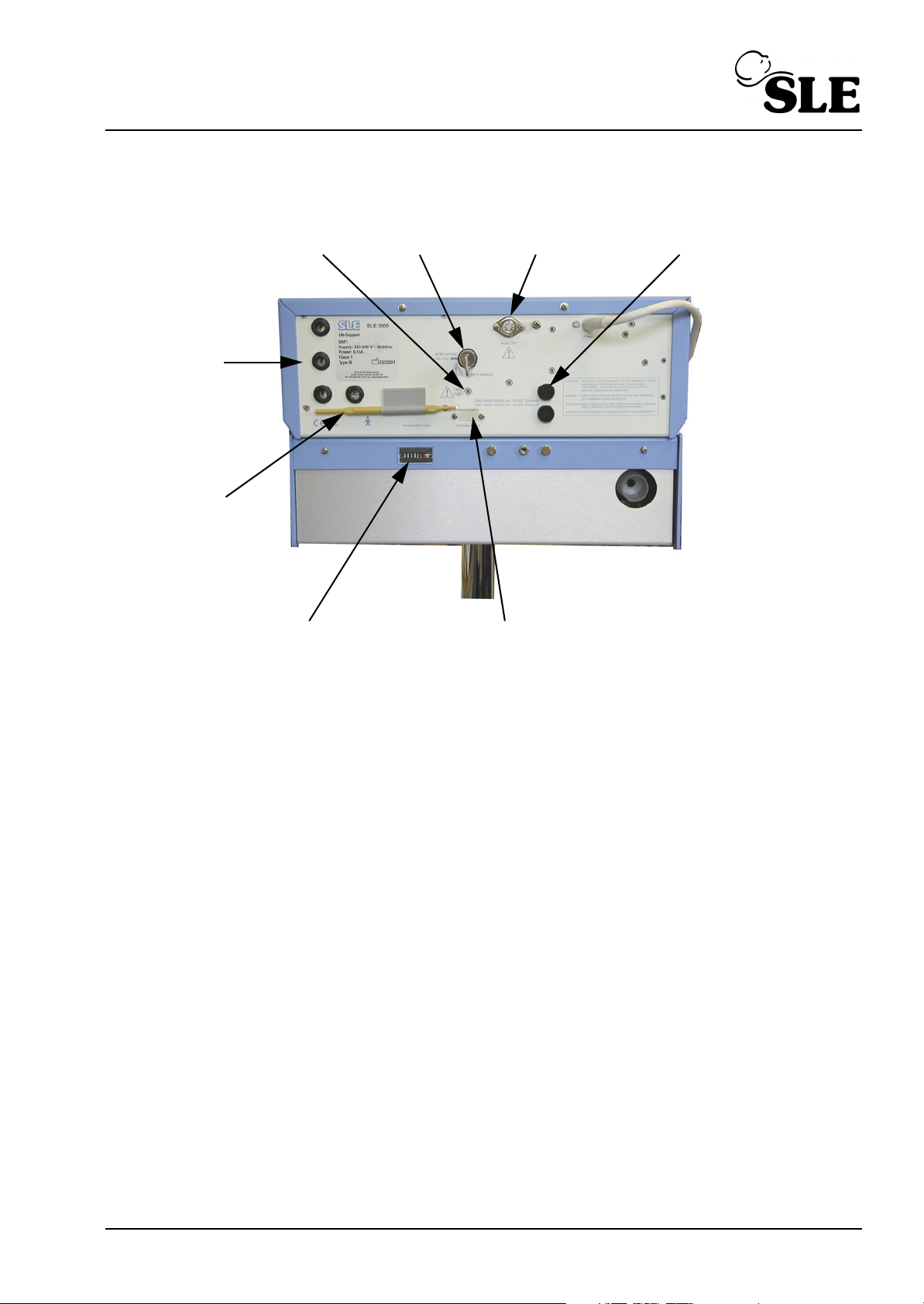
7.3 Rear panel
7
3
6
2
5
4
1
8
Nº Item
1FIO
calibration adjustment.
2
2 125 - 250 BPM range switch
3 Aux. Output socket.
4 Fuse Holders
5 Optional serial port
6 Running Time Indicator
7FIO
adjustment tool.
2
8 Alarm sounder
(SLE2000) Page 19
Page 20
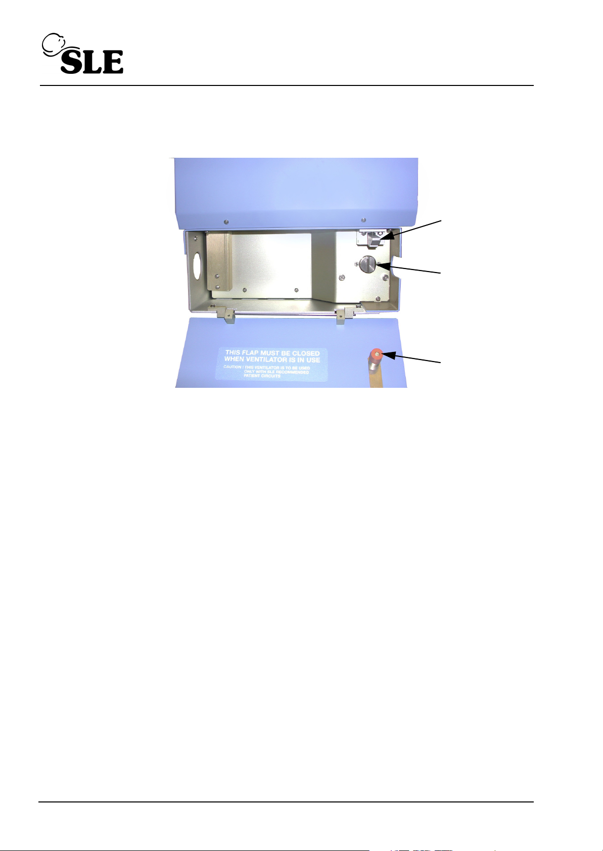
7.4 Side panel
3
2
1
Nº Item
1 Side flap latching mechanism.
2 Fixed jet.
3 Expiratory tube guide.
Page 20 (SLE2000)
Page 21

Access to Internal Components
(SLE2000) Page 21
Page 22
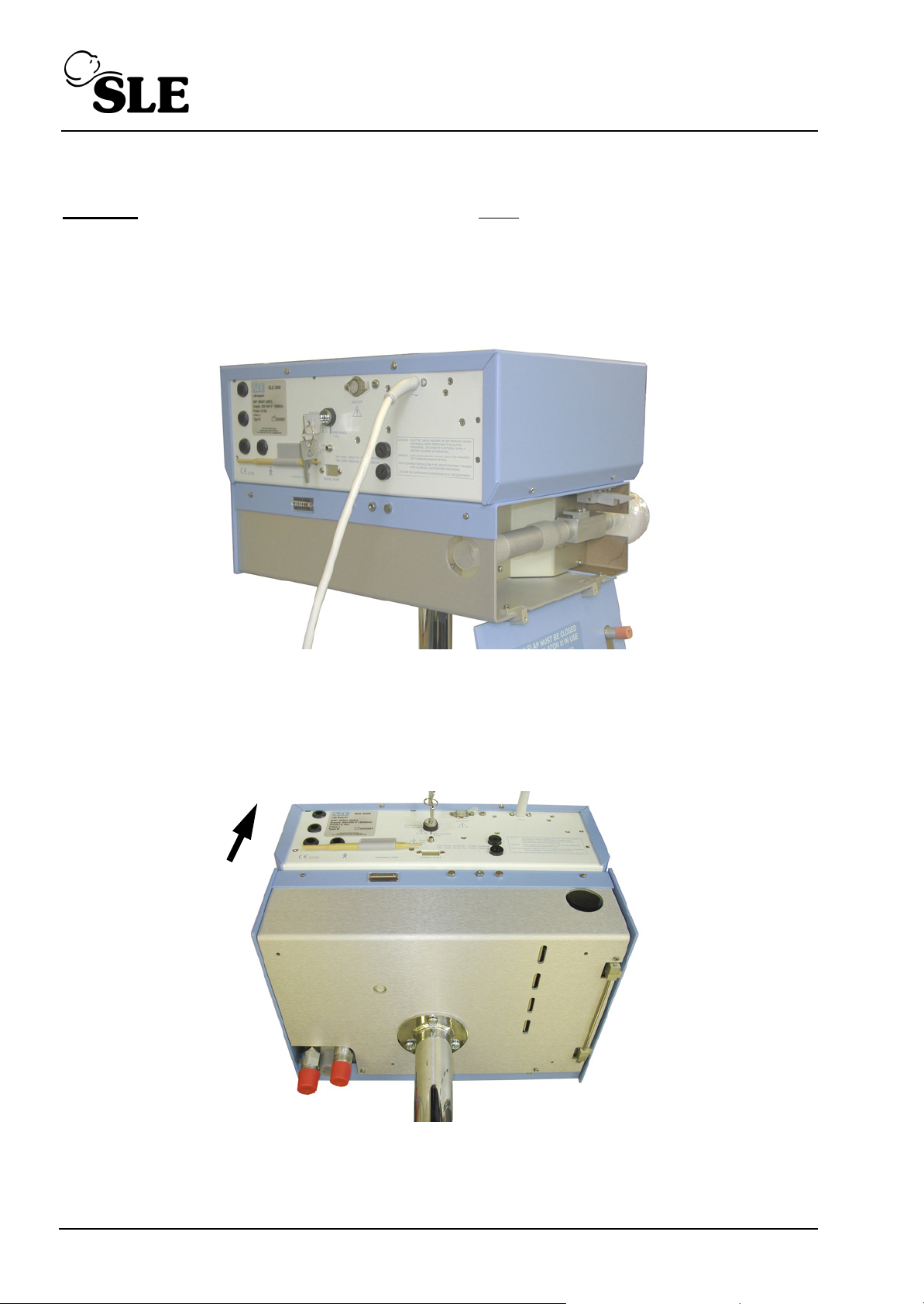
8. Accessing the SLE2000 internal components.
A
A
B
B
D
D
E
E
C
Caution: All electrical and pneumatic connections must be disconnected before attempting
to gain access to either Electronic or Pneumatic modules.
8.1 ELECTRONIC MODULE
1. Remove 2 screws at rear (A) and 2 screws at each side of the unit (B).
2. Slide top cover to rear and remove.
8.2 PNEUMATIC MODULE
1. Open Side Flap (C).
2. Remove 2 screws at rear (D) and 2 screws at base of unit (E).
3. Lift complete unit from base and turn upside down.
Page 22 (SLE2000)
Page 23
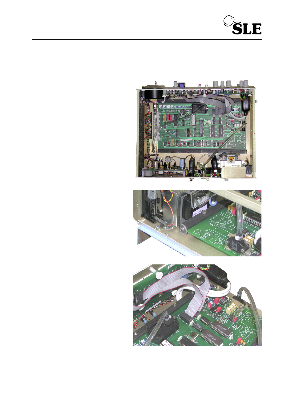
8.2.1 To Remove the A0702/01 PCB (Runner mounted)
A
A
B
C
C
D
Caution: Observe anti static precautions when handling the PCB.
1. To remove the main PCB A0702/01
loosen the two retaining washers
(A.)
2. Cut the cable tie connecting the
fresh gas tube to PTR1 (B)
3. Pull the fresh gas tube from the
transducer.
4. Disconnect the two ribbon cables
(C) from the PCB
5. Cut the cable tie connecting the
Proximal Airway Tube to PTR1 (D)
6. Pull the Proximal Airway Tube from
the transducer.
7. The PCB can now be removed.
(SLE2000) Page 23
Page 24
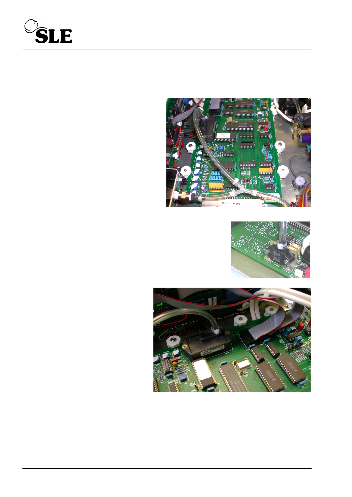
8.2.2 To Remove the A0702/01 PCB (Pillar mounted)
A
A
B
C
C
D
Caution: Observe anti static precautions when handling the PCB.
1. To remove the main PCB A0702/01
loosen the two retaining nuts (A.)
2. Loosen the all the white thumb nuts.
3. Cut the cable tie connecting the fresh gas tube to PTR1 (B)
4. Pull the fresh gas tube from the transducer.
5. Disconnect the two ribbon cables (C)
from the PCB
6. Cut the cable tie connecting the
Proximal Airway Tube to PTR1 (D)
7. Pull the Proximal Airway Tube from
the transducer.
8. The PCB can now be removed.
Page 24 (SLE2000)
Page 25

8.3 To Separate The Two Modules
A
A
A
View A
B
C
D
A
View A
1. Invert ventilator to gain access to the base of the pneumatic module.
2. Remove the four screws (A).
3. Remove proximal airway pressure tube connection (B).
4. Remove Fresh gas monitoring tube connection (C).
5. Release both locking screws and disconnect the 15 way plug (D).
It is now possible to separate the pneumatic module from the electronic chassis.
(SLE2000) Page 25
Page 26
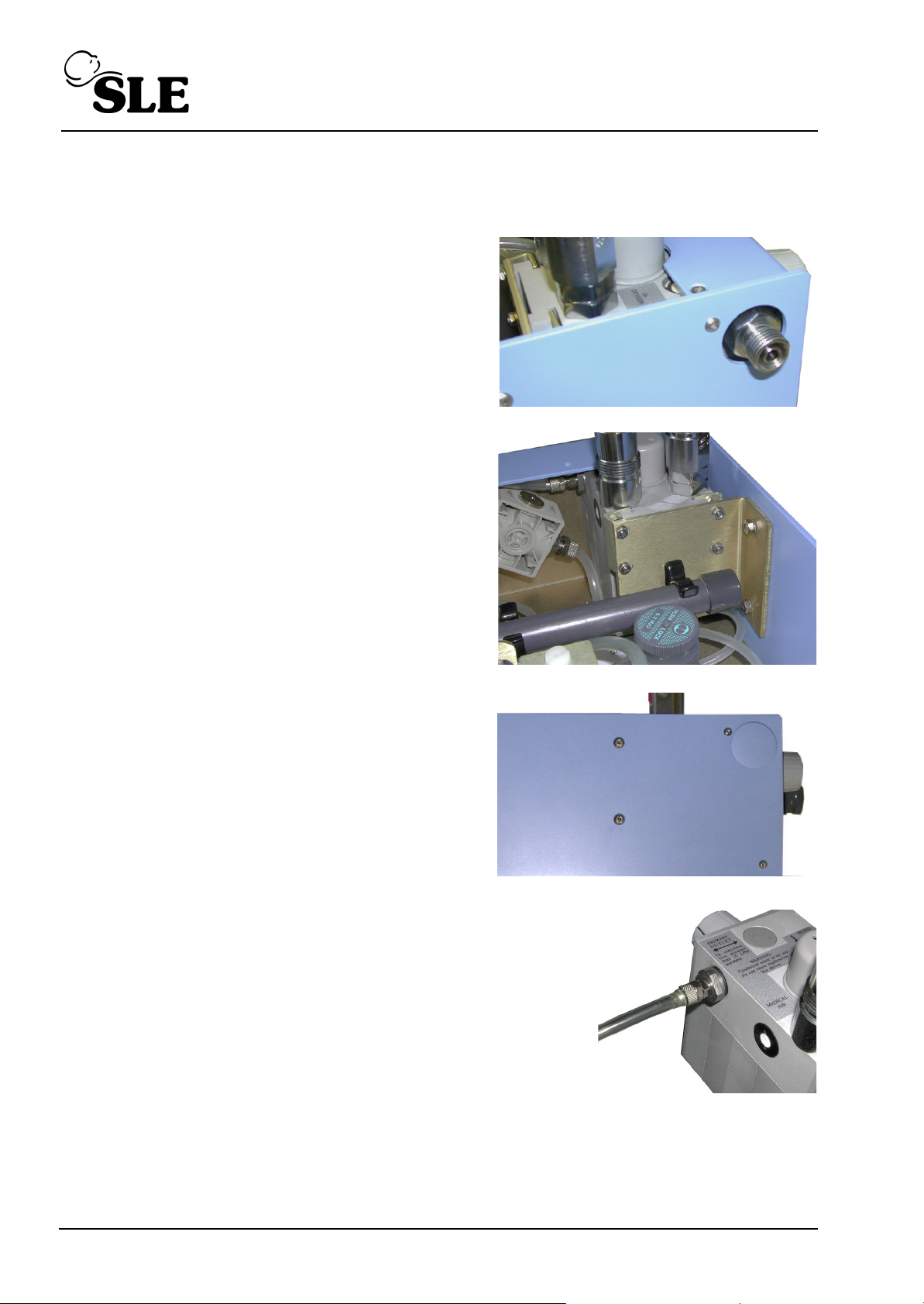
8.4 Removal Of The Oxygen Blender
A
B
C
D
1. Gain access to the pneumatic module.
2. Remove the flowmeter outlet (A) (if fitted).
3. Unclip the large volume chamber (B) and move it
to one side. It is not necessary to disconnect the
tubing connector.
4. Undo and remove the two nuts, screws and
washers (C) from the side panel.
5. It is now possible to manoeuvre the Oxygen blender out of
the front panel aperture a sufficient distance to enable the
main supply connector (D) to be uncoupled.
6. It will now be possible to completely remove blender from
module.
To install new blender repeat the above process in reverse order.
Page 26 (SLE2000)
Page 27
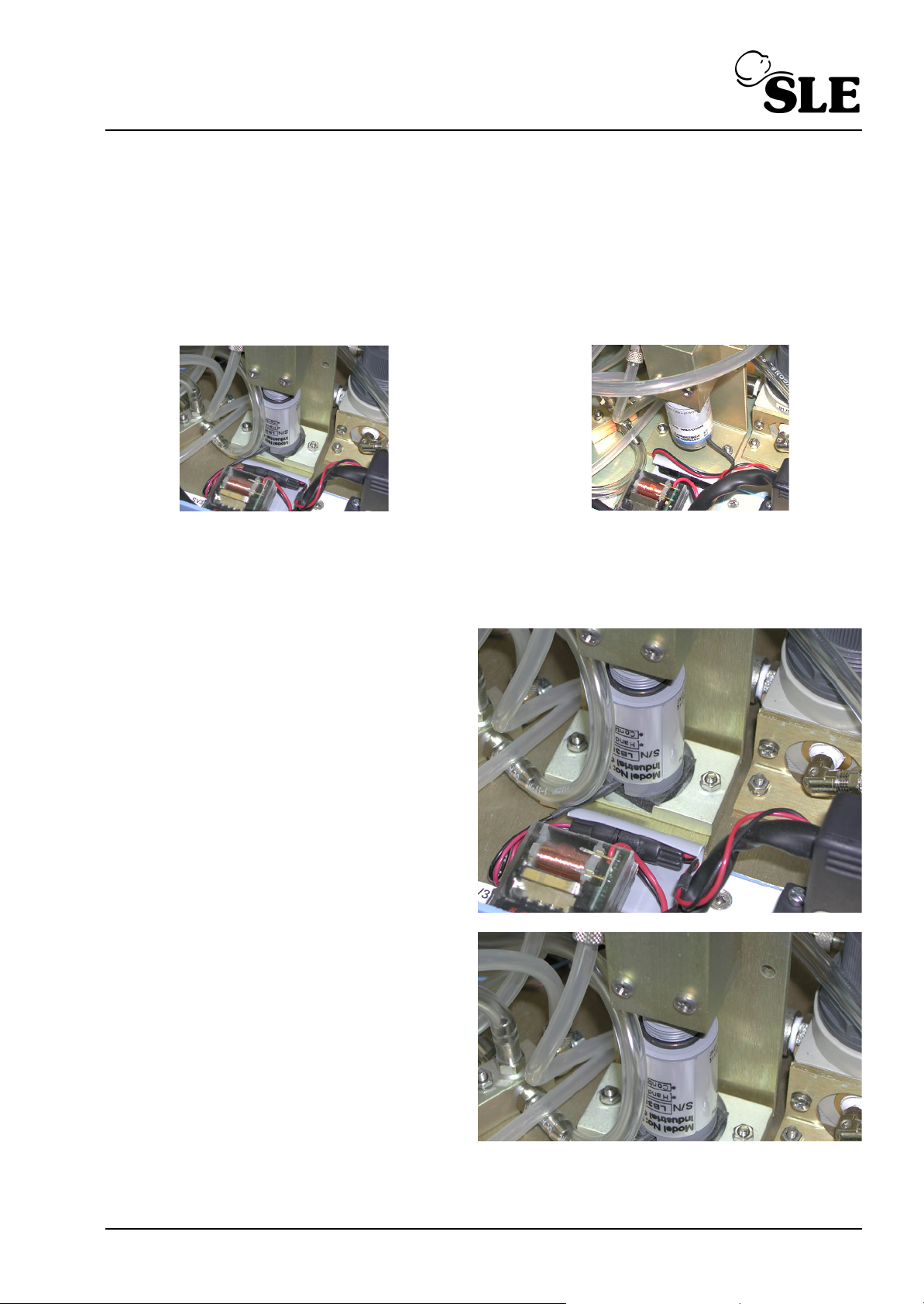
8.5 Removal of the Oxygen cell
Photograph A
Photograph B
A
B
B
Firstly gain access to the pneumatic module
8.5.1 Oxygen Cell Mounting
The SLE 2000 ventilator has two methods of mounting the Oxygen cell. The first method the
oxygen cell is trapped between the manifold and a foam pad, Photograph A.
The second the oxygen cell is screwed directly into the manifold, Photograph B.
8.5.1.1 Method A for Trapped cell.
1. Disconnect the cell connector (A).
2. Remove the two screws (B) retaining the
manifold and lift it clear.
(SLE2000) Page 27
Page 28
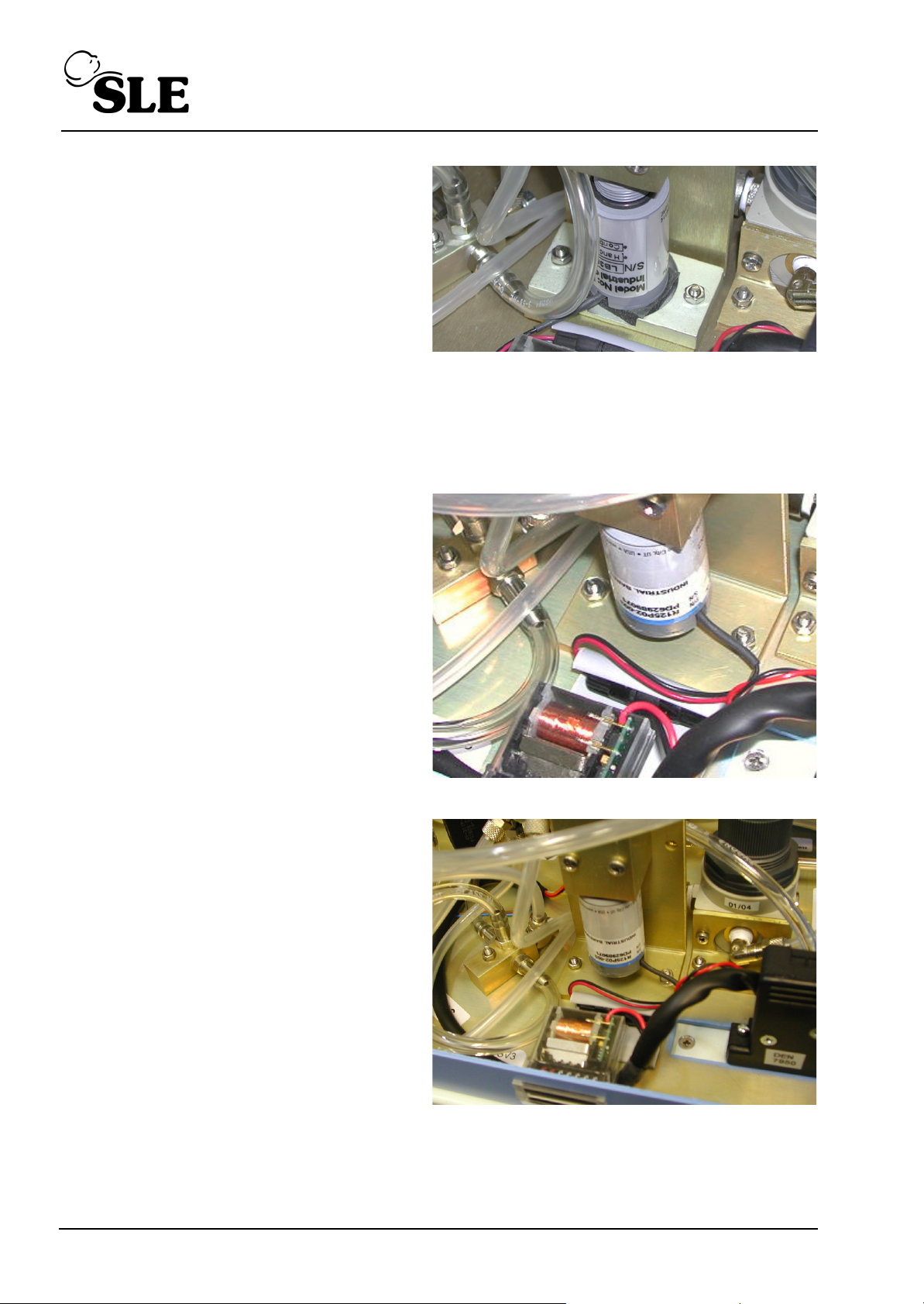
3. Remove old foam retaining pad (C) from
C
D
E
E
mounting base (if applicable)
4. Assembly is the reversal of removal.
5. Replace cell (Part No. N2191) and
reconnect the electrical connector.
6. Ensure that the foam rubber pad is fitted between the cell and the mounting base and that
the gas seal “O” ring is fitted to the manifold. After refitting, recalibrate the cell.
8.5.1.2 Method B for Screw in cell.
1. Disconnect the cell connector (D).
2. Remove the two screws (E) retaining the
manifold and lift it clear.
3. Unscrew the old cell.
4. Assembly is the reversal of removal.
5. Screw in the new cell (Part No. N2191)
and reconnect the electrical connector.
After refitting, recalibrate the cell.
Page 28 (SLE2000)
Page 29

Maintenance
(SLE2000) Page 29
Page 30

9. Maintenance
9.1 Cleaning, disinfection and sterilization
All cleaning, disinfection and sterilizing should be carried out under the direction of the
appropriate hospital authority.
DO NOT allow moisture to enter the electronic module or its electrical sockets. Electronic
malfunction may result.
DO NOT steam autoclave the SLE 2000 or otherwise subject it to temperatures above 62°C.
DO NOT immerse any part of the SLE 2000 in any liquid, with the exception of the expiratory
exhalation block (SLE part No N2190).
9.1.1 Preparation of a new ventilator
Remove all transit packaging. Inspect the fresh gas port and proximal airway port for any
packing material. (Retain packaging for future use as the ventilator must be returned in its
original box).
Clean, disinfect and sterilize in accordance with the instructions in section 9.1.2 .
Remove the inlet air and O2 gas port caps. (Retain for future use).
9.1.2 Cleaning and disinfection of an in-service ventilator
The table 1 outlines the areas of the ventilator which can be uniquely cleaned, disinfected
and sterilized.
Before cleaning or disinfecting the exterior of the ventilator the following tasks should be
performed:
• The mains cable should be disconnected from the mains supply.
• Remove the patient circuit and bacterial filters. Discard any single use items as per
appropriate hospital authority guidelines. Reusable items should be processed as
per appropriate hospital authority guidelines and the manufacturers instructions.
• Disconnect the gas supplies from the wall outlets.
• Disconnect the Oxygen and Air hoses from the ventilator and cap the inlet ports.
Page 30 (SLE2000)
Page 31
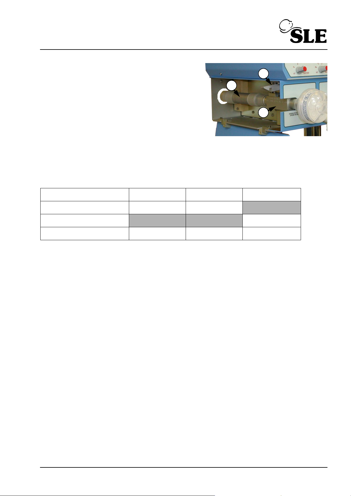
• Lift up lever (A) on side of ventilator and
A
B
C
lower side flap.
• Remove the silencer (B) by pulling it
through the hole at the rear.
• Remove the exhalation block (C) by firstly
taking hold of the block and then pulling it
out towards you without the need for
undue force.
Refitting the silencer and exhalation block is the reversal of removal. Do not force the
exhalation block into place.
9.1.3 Cleaning, Disinfection & Sterilization chart
Item Clean Disinfect Sterilize
Ventilator Yes Yes
Silencer Yes
Exhalation block Yes Yes Yes
Table 1
Warnings (General): Do not insert any object (such as a needle) in to the gas ports.
This action will result in damage to the port. If the user believes there is a foreign
object in a gas port, please refer the ventilator to qualified service personnel for
inspection and repair.
Note: The silencer should be autoclaved only. If the silencer is found to have visual
contamination internally, discard and replace with a new silencer.
9.1.4 Cleaning method Note: Cleaning is an essential prerequisite to disinfection and sterilization.
Ventilator. For cleaning use three clean, disposable, absorbent, non-shedding cloths. Wipe
clean with the first cloth using a hand hot water/mild general purpose detergent solution (as
prescribed by the appropriate hospital authority). Do not overload the cloth with liquid.
Remove the water/mild general purpose detergent solution with the second cloth using water
only. Do not overload the cloth with liquid. Wipe dry with the remaining cloth. Care should be
taken to ensure that the ventilator gas jets in the ports are not blocked by any debris.
Exhalation block. The exhalation block can be immersed and agitated in the detergent
solution. Do not insert any objects into the exhalation block. Rinse the exhalation block in
clean water, it must be allowed to dry thoroughly before sterilization.
Warning: Ensure that the detergent solution or water does not enter the unit or the
exhalation block gas ports on the side of the machine.
(SLE2000) Page 31
Page 32

9.1.5 Disinfection method Note: Alcohols such as 70% isopropanol have a good activity against bacteria and
viruses. They should only be used after all visible surface dirt has been removed from
the area to be disinfected.
Ventilator. For disinfection use two clean, disposable, absorbent, non-shedding cloths.
Wipe clean with the first cloth using Alcohol (70% isopropanol). Wipe dry with the remaining
cloth.
Exhalation block. The exhalation block can be immersed in Alcohol (70% isopropanol).
The exhalation block must be allowed to dry thoroughly before sterilization.
9.1.6 Sterilization method
The silencer SLE part Nº N2186 and exhalation block SLE part Nº N2190 must be sterilized
between use on patients. The ventilator cannot be sterilized.
The exhalation block must be cleaned as an essential prerequisite to sterilization.
Autoclave with pure dry saturated steam at:
134ºC (277ºF) (Allowable variation of temperature of +3ºC) at 220kPa (32psi) with a
minimum holding time of 3 minutes
or
121ºC (248ºF) (Allowable variation of temperature of +3ºC) at 96kPa (14.1psi) with a
minimum holding time of 15 minutes.
There is no limit on number of autoclave cycles for the exhalation block.
The silencer can be autoclaved up to 20 times. The body of the silencer should be marked
after each autoclave cycle with a high temperature, water proof, permanent maker to
indicate number of sterilization cycles completed.
Page 32 (SLE2000)
Page 33
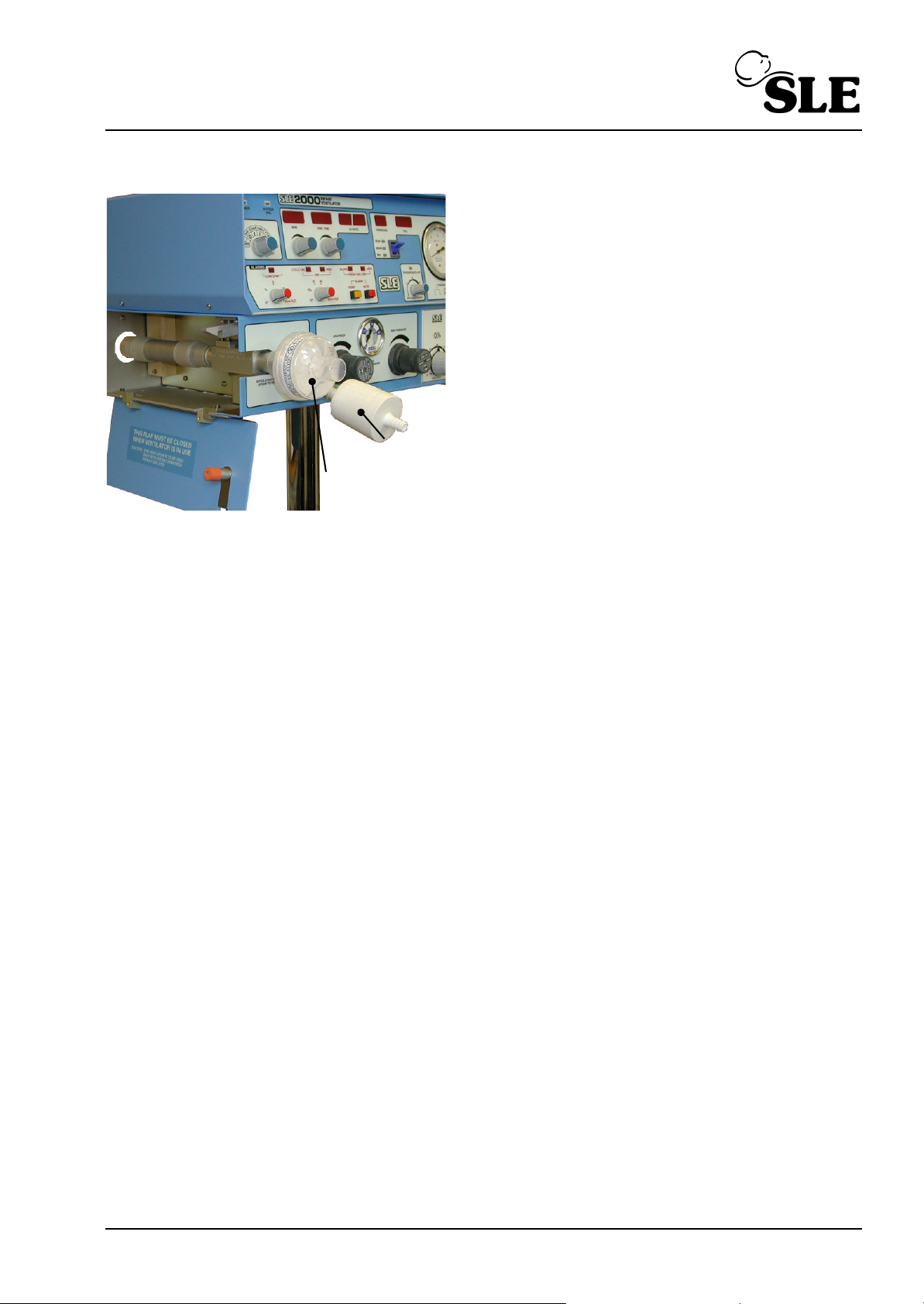
9.2 Filter systems
Bacteria Filter
N2587
Bacteria
Filter N2029
IIt is recommended that bacteria filters are fitted
in the fresh gas supply and on the patient side of
the exhalation block.
The filters reduce the possibility of infection to the
patient and contamination of the ventilator from
secretions or fluids in the breathing circuits that
could accidentally enter the ventilators gas ports.
It is recommended that a silencer be fitted on the
exhaust side of the exhalation block, this helps to
reduce the noise level of the system.
The SLE2000 can be used without bacterial filters
in place, but the user must take extra care in not
allowing secretions or fluids to enter the ventilators gas ports.
9.2.1 Bacterial filter, SLE Part Nº:N2029 (Autoclavable)
This autoclavable bacterial filter is fitted into the humidifier supply line and has to be fitted in
accordance with the indicator arrow embossed on the surface of the filter.
Do not immerse the filter in any liquid.
Autoclave with pure dry saturated steam at:
134ºC (277ºF) (Allowable variation of temperature of +3ºC) at 220kPa (32psi) with a
minimum holding time of 3 minutes
or
121ºC (248ºF) (Allowable variation of temperature of +3ºC) at 96kPa (14.1psi) with a
minimum holding time of 15 minutes.
The filter can be autocalved a maximum of 25 times within its anticipated service life of 12
months. For other makes of bacterial filter please refer to manufacturers instructions.
9.3 Bacterial filter, SLE Part Nº:N2587 (Single use)
This single use bacterial filter is fitted onto the exhalation block outlet. This filter should be
disposed of in accordance with local hospital authority guidelines. A new filter should be
used for every new patient.
9.3.1 Precautions when using bacterial filter N2587
The user should be aware that any occlusion of the filter increases the resistance to airflow,
resulting in increased or erratic airway pressures. Airway pressures should be monitored
during use and the filter changed if found to be contaminated in any way. When using
humidification the filter should be checked regularly for signs of water build up which could
cause occlusion.
(SLE2000) Page 33
Page 34

9.4 Monthly operational checks
9.4.1 Battery condition and LED display test.
Switch unit to CPAP position. All alarms should sound for two seconds. All digital displays
should show a sequence of digits from 0 to 9 and all alarm LED's (except the Block LED) will
be on for the duration of this test.
9.4.2 Air and oxygen supply failure alarm test.
With the FIO
blender set to 60% remove in turn both air and oxygen supplies. Check that in
2
each case the alarm sounds, and on replacement the alarm cancels.
9.4.3 Condition of O
cell
2
Set blender to 21% and observe that displayed FIO2 is 21%. Set blender to 100% and
observe that displayed FIO2 is 100%. Adjust if necessary. If error prior to adjustment
exceeds 10% replace O2 cell.
9.4.4 Proximal airway pressure gauge accuracy
Set ventilator to CMV; 60 BPM: 0.5 sec. inspiration time. Adjust PIP pressure to 50 cmH2O
digitally displayed. Compare digital pressure display with mechanical gauge. Error should
not exceed 3%.
9.4.5 Inspiratory nozzle
Turn the inspiratory pressure regulator fully clockwise, adjust PIP alarm fully clockwise. Set
ventilator to CMV: 60BPM: 0.5 sec inspiration time. Peak inspiration pressure should be
greater than 60 cmH2O.
Page 34 (SLE2000)
Page 35

9.5 Preventative maintenance
Preventative maintenance should be completed at a maximum of every 5000 hours
operation or at 6 monthly intervals. This maintenance is intended to be carried out in the
hospital.
Preventative Maintenance will include :
• Visual inspection and cleaning of all exterior surfaces, controls, attachments and
accessories.
• Removing the covers and cleaning all dust from the interior of the unit.
• Visual inspection of all tubing, electrical wiring, connectors, crimps, screws, nuts,
hardware and checking the general condition of all other internal components and
assemblies.
• Inspection of the mains failure battery holder for corrosion and replacement of the
battery.
• Pneumatic and electronic testing and where necessary calibration of ventilator.
• Replacement of orifice block ‘O’ ring.
9.6 Overhaul
Overhaul should be carried out at a maximum of 10,000 hours operation or every two years
of service which ever is sooner. This overhaul will be performed by an SLE trained hospital
engineer or an SLE service engineer.
In addition to the checks and items performed during the preventative maintenance, an
overhaul will include :
• Replacement of oxygen monitor cell,
• Replacement of oxygen blender,
• Replacement of main solenoid SV1,
• Replacement of PIP and CPAP regulators
• Replacement of orifice block ‘O’ ring.
• Replacement of battery.
• Checking operation and general condition and replacing where necessary the following
components :
Solenoid valves SV2 and SV3.
Tubing and connectors
Battery holder
Alarm sounders
Mode, wave shape, frequency range and pressure range switches.
Pressure relief valves.
SLE offer an exchange service for the pneumatic module.
(SLE2000) Page 35
Page 36

9.6.1 Service parts list
Preventative Maintenance 5,000 Hour
Item Part Number
‘O’ Ring N2042
Battery M0484/03
Overhaul 10,000 Hour Service or 2 Years
Item Part Number
Blender N2185/02
Oxygen Cell N2191
Solenoid Valve SV1-SV3 N2195/05
0-4 Bar regulator N2181
0-2 Bar regulator N2182
‘O’ Ring N2042
Battery M0484/03
10,000 hour overhaul kits
Part number
Overhaul kit for NON CE SLE2000 N9000
Overhaul kit for CE SLE2000 N9000/01
Page 36 (SLE2000)
Page 37

Technical Description
(SLE2000) Page 37
Page 38

10. Electronic module description
The SLE 2000 is arranged in two modules. The Electronic Module is the upper of the two
modules which contains all of the electronic controls and displays.
10.1 Description of operation
Refer to circuit diagram “Ventilator CPU Board CD/A0702/01 Issue 6” on page 85. The
processor board comprises the main microprocessor and ventilator control circuitry, the
display drivers, the patient trigger system, and pneumatic alarm circuitry
The processor (U14) is an 80C31 running at 11.0592MHz. It is an 8 bit processor,
employing time multiplexed address and data operations. Software is provided by the
EPROM (U6).
Analogue input parameters from panel control settings (BPM rate, inspiration time, CPAP
alarm threshold, PIP alarm threshold) are converted to digital 8 bit words by the ADC (U18)
which scans each input in turn. Open circuit input fault conditions are detected by software
and pull-up resistor array (RU3). Switched input parameters (mode, Range, Reset, Mute,
Pressure display Mode) are scanned by (U12).
Confirmation of correct solenoid valve energisation voltages is fed to (U14/14) by potential
divider R34, R32 and clamp D3.
Supply voltage supervisor (U7) will attempt to reset the processor (U14/9) should the logic
supply voltage of 5.12V dc fall below 4.8V dc. It also holds the processor reset for a 2
second test period on power up.
Unlatched audible alarm BZ1 (BZ5 and BZ6 when the A0703/03 board fitted) is activated
when any analogue input is detected to be outside the predetermined range. It is driven
from (U14/4) via (U13) to PLB 7a. In conjunction with BZ1 or BZ5/BZ6 there are three visual
latched alarms (CPAP Fail, High Pressure, Cycled Failed); all are processor activated from
outputs (U14/2,6,1) which are buffered by (U10) and connected to PLB 14a, 3b, and 14b
respectively. The buffered high pressure alarm output also de-energises the dump valve
solenoid via PLB20b.
Trigger back-up and alarm mute indication LED's are driven by the processor from (U14/5)
and (U14/7) via buffer (U10) and are connected to PLB3a and PLB 15b.
The main PIP solenoid valve and the waveshape solenoid valve are driven from (U14/8 via
buffer (U10) and MOS driver Q4.
The LED Board A0701/01 (See “LED Circuit Board Diagram CD/A0701/01” on page 74.)
accommodates the max., mean, min. LED buffer (U400) and LED’s CPAP, Cycle Fail, High
Pressure, Block, Leak and Trigger.
Page 38 (SLE2000)
Page 39

(U1) and (U2) are 7 segment display drivers.
There is a supervisory watchdog alarm system which consists of (U8) and BZ2 (BZ5 and
BZ6 when the A0703/03 board fitted). This monitors a train of 10ms pulses from (U14/3) to
confirm the correct running of the software. A disruption of these pulses will activate a
latched audible alarm BZ2 or BZ5/BZ6. In addition, reset pulses from (U7/6) to (U14/9) will
attempt to restart the software until the 10ms watchdog pulses are restored.
The Mains Failure Alarm relay RL1 is energised from the 5.12 volt logic supply and holds
pins 1 and 14 open. Should the relay de-energise contacts 1 and 14 will close, and a battery
powered alarm will be activated via connections PLB 18a and PLB 20a.
On power-up, a short test period is initialised. Time constant R2, C5 via (U4) forward biases
(Q1) for approx. 2 seconds, therefore shorting PLB 18a and PLB 20a and operating the
battery alarm.
PTR1 is connected to the proximal airway pressure line. (U13/1, 2, 3) and associated
components form an 8V dc voltage regulator. (U13/8. 9, 10) process the analogue voltage
output from PTR1 into the range 1-3.4V corresponding to pressures of 0-40 cmH2O prior to
A to D conversion. (U13/5, 6, 7) process the analogue voltage output to the range 1-6V dc
for an input of 0-50 cmH2O for an analogue output signal.
Fresh gas failure pressure transducer PTR2 monitors the fresh gas supply pressure
transducer PTR1 monitors the fresh gas supply pressure and activates the audible alarm
BZ3 (BZ5 and BZ6 when the A0703/03 board fitted) and also drives the leak alarm LED
should the pressure fall below 17.5 cmH2O. If the pressure rises above 80 cmH2O then the
block LED is operated and the audible alarm will activate.
(SLE2000) Page 39
Page 40

11. Pneumatic module description
11.1 Description of operation
Air and oxygen supplies are connected directly to the blender. The output of the blender is
supplied via panel mounted regulator REG.1 (inspiratory pressure) and solenoid valve SV1
to the inspiratory nozzle in the exhalation block. It is also connected to the normally closed
port of the wave shape solenoid (SV3) and the large volume chamber.
In inspiration mode the valve SV1 opens and allows a flow of blended gas into the patient
circuit via the inspiratory nozzle. This flow opposes the constant fresh gas flow and creates
an inspiratory pressure.
The function of the large volume chamber and valve SV3 is to delay this flow of gas during
the inspiratory phase when the pressure wave switch is set to taper. On expiration SV3 deenergises and dumps to atmosphere so that the expiratory airway pressure falls rapidly as in
square mode.
REG2 (CPAP) is also supplied from the oxygen blender. This front panel mounted regulator
controls the flow of blended gas from the CPAP nozzle in the exhalation tube. This gas
being a constant flow in opposition to the fresh gas flow creates a CPAP/PEEP pressure in
the patient circuit.
NOTE any changes of CPAP pressure will also change the peak inspiratory pressure. This
is arranged so that the tidal volume is always constant and unaffected by changes in CPAP.
REG3 is an internal regulator which regulates the blended gas to a working pressure of 10
PSI. NV1 is adjusted to set a 5 LPM blended gas flow into the fresh gas port on the front
panel when SV2 is activated (eg the ventilator is powered up). This flow passes through
valve SV2 (fresh gas dump solenoid) which will dump the fresh gas should the patient circuit
pressure reach the high pressure alarm threshold. When SV2 is deactivated (ventilator off or
fresh gas dumped) then the fresh gas flow is 1LPM. This residual flow is to ensure correct
operation of the humidifier.
RV2 is an additional relief valve which activates at fresh gas pressures above 140cmH2O.
NV2 sets a 7LPM bleed to atmosphere. This flow combined with the 5LPM fresh gas flow
ensures that the oxygen blender has the 12LPM flow through it required to maintain its
accuracy. This bleed is also fed to the oxygen monitoring cell, whose output is connected to
the digital F102 display circuitry in the electronics module.
Page 40 (SLE2000)
Page 41

The fresh gas transducer PTR2 is mounted in the electronic module and monitors the patient
airway pressure. The SLE 2000 because of its unique principle of operation will ventilate the
patient without the fresh gas supply. In order to ensure that the patient is always being
supplied with fresh humidified gas, a restrictor is fitted in the patient fresh gas tubing close to
inspiratory port of the ET connector. The restrictor maintains a circuit pressure of
approximately 20 cmH2O. This pressure is monitored by PTR2 to be within the range 17.5-
80 cmH2O. A leak or a blockage condition in this circuit causing the pressure to be outside
of these limits will activate the respective alarms. A pressure above 80 cmH2O will cause the
block alarm and LED to operate and dump the fresh gas via SV2. If the pressure falls below
17.5 cmH2O then the leak alarm and LED will be activated.
(SLE2000) Page 41
Page 42
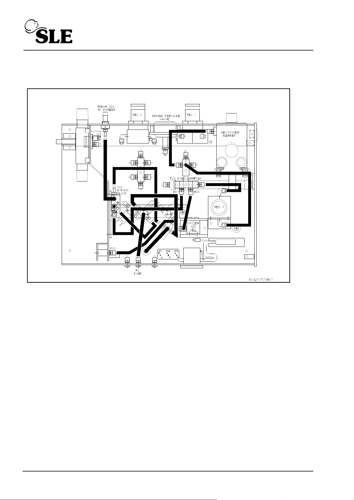
11.2 Fresh Gas System
Gas from the AIR/OXYGEN Blender is supplied to the preset regulator REG3 via the supply
manifold. The output of REG3 is set to 10PSI and is fed to two flow valves.
NV2, which is set to a flow of 7LPM and dumps to atmosphere via the O2 cell.
NV1, which is preset to 5LPM and supplies the fresh gas to the patient circuit via SV2 (high
pressure dump solenoid) and a circuit preset pressure relief valve RV2.
The SV2 bypass provides a continuous flow of 1LPM through the humidifier in the event of a
high pressure dump.
Page 42 (SLE2000)
Page 43
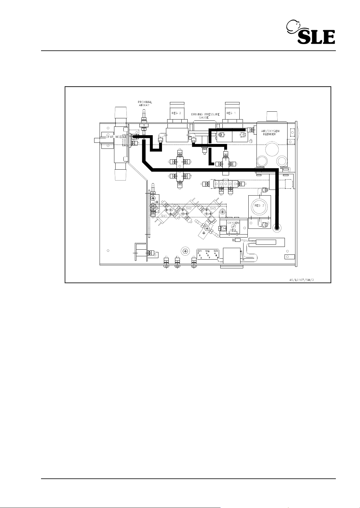
11.3 CPAP System
Gas from AIR/OXYGEN Blender is supplied to the CPAP pressure regulator REG2 via the
supply manifold. The output pressure of REG2 is fed to the CPAP nozzle in the expiratory
manifold, and into the expiratory limb of the patient circuit to create the circuit CPAP
pressure.
(SLE2000) Page 43
Page 44
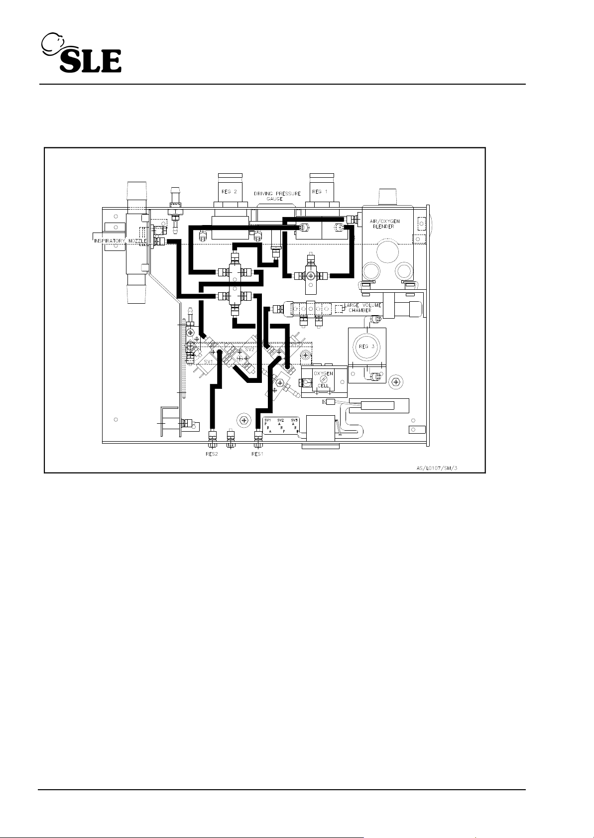
11.4 Inspiratory System
Gas from the AIR/OXYGEN Blender is supplied to the user adjustable PIP regulator REG1
through the supply manifold. The output pressure of REG1 is supplied to the inspiratory
nozzle via the solenoid valve SV1 which controls the breathing rate. If the pressure wave
switch is in the taper position then SV3 is energised and the inspiratory flow enters the large
volume chamber before reaching the inspiratory nozzle, thus lengthening the pressure rise
time.
Page 44 (SLE2000)
Page 45
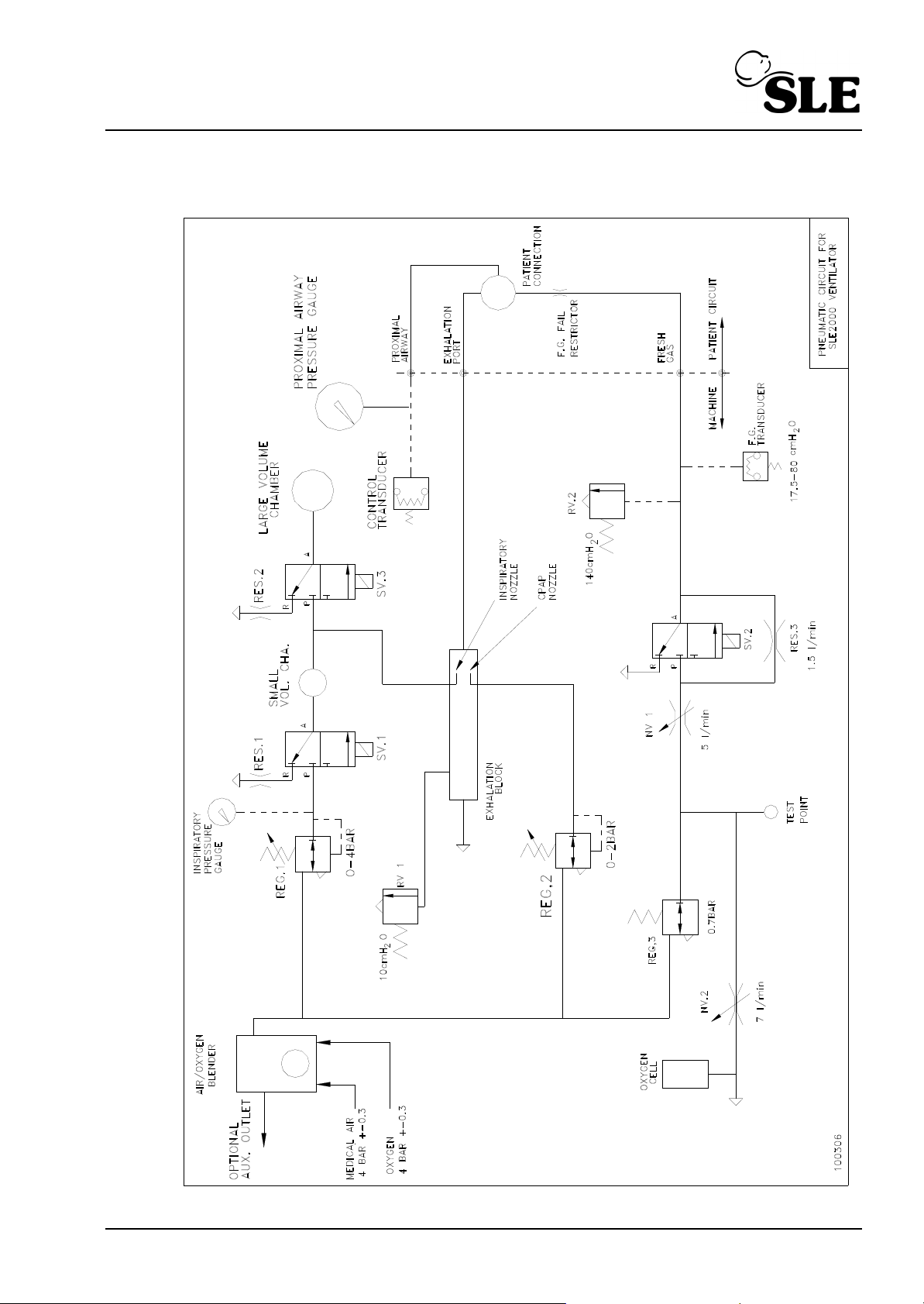
11.5 Pneumatic Circuit Diagram
(SLE2000) Page 45
Page 46
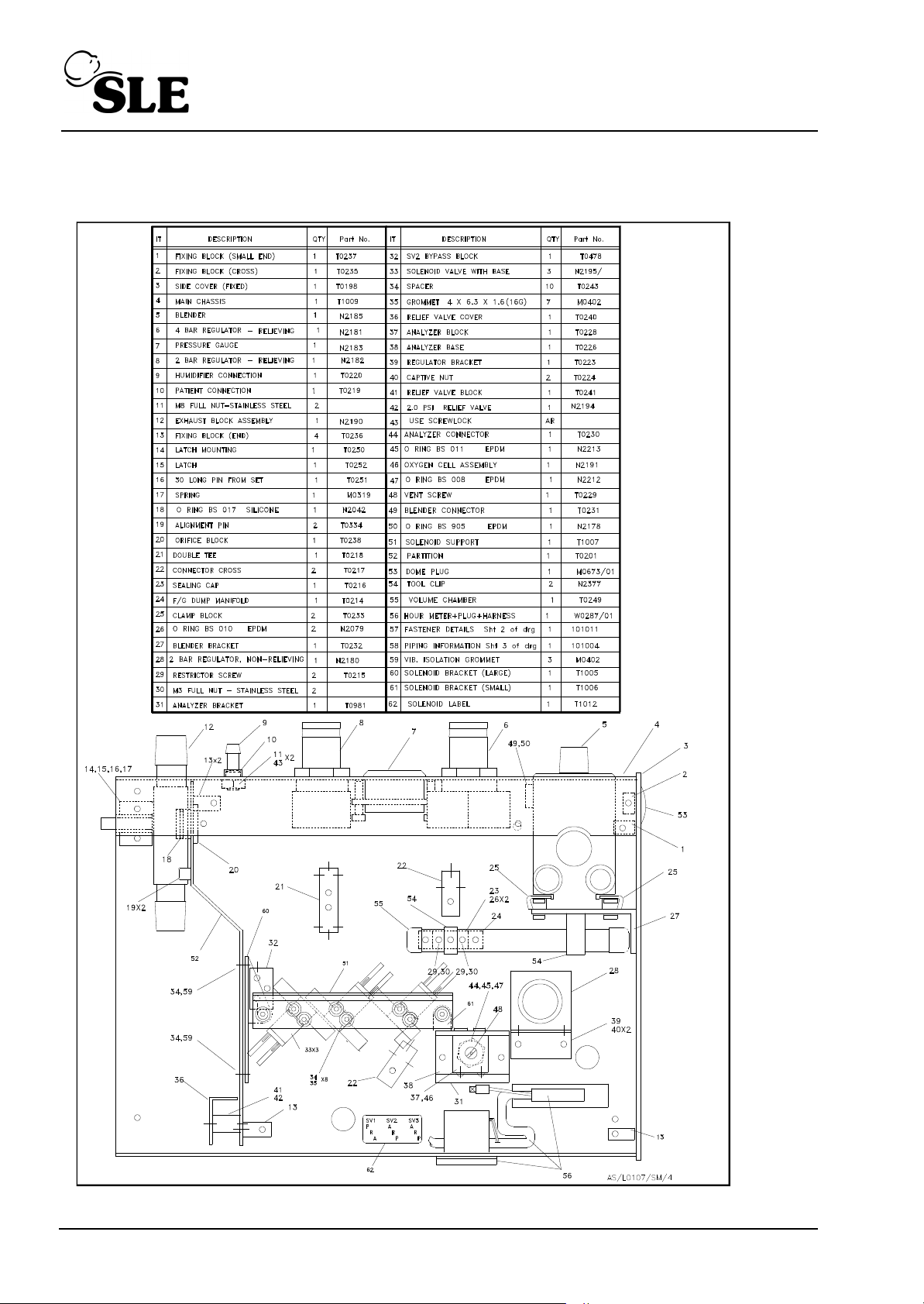
11.6 Pneumatic Module Parts List
Page 46 (SLE2000)
Page 47
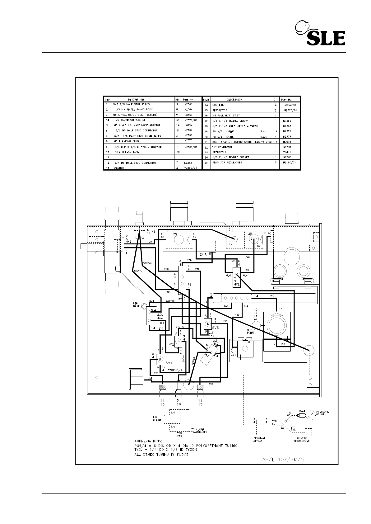
(SLE2000) Page 47
Page 48

This page is intentionally blank.
Page 48 (SLE2000)
Page 49

Setup and Calibration
(SLE2000) Page 49
Page 50
12. Test Equipment Required
The following test equipment is required to perform the calibration and set up procedures as
described in See “SLE2000 Calibration Procedure” on page 51.
Electronic: Digital multimeter.
Twin beam oscilloscope.
Pneumatic: Multi-range Pressure and Flow analyser .
O
Analyser.
2
Miscellaneous: Connectors and tubing.
Metric hexagonal keys 3mm, 2.5mm, 2mm.
2mL syringe.
10mL syringe.
Variable Flow Restrictor
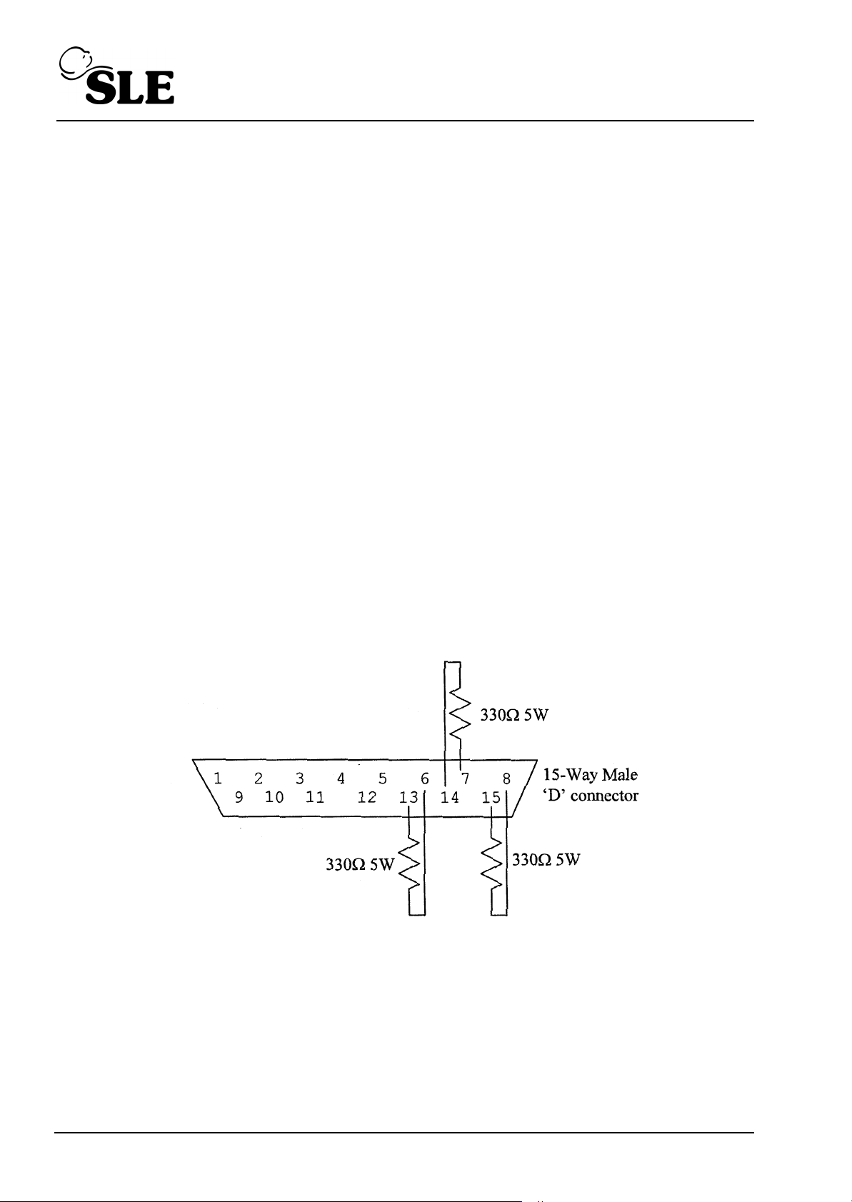
Electronic Module Dummy Load (optional):
This is a test load which plugs into the 15 way ‘D’ connector on the base of
the electronic module. It emulates the resistive loads of the pneumatic
module solenoids thus allowing the electronic unit to be tested in isolation.
details as follows;
Page 50 (SLE2000)
Page 51
13. SLE2000 Calibration Procedure
Note: If electronic module is being set up without the pneumatic module attached, then a
dummy load must be connected to 15 way 'D' connector on base of module as a substitute
for the solenoid valves. (See “Test Equipment Required” on page 50.)
13.1 Electronic unit preliminary checks and adjustment
Connect to mains power and set the mode to CPAP.
Monitor PLB 32b and adjust RV 102 on the Power Supply PCB (A0703) to give 5.12V
10mV.
Check that PLB 1b is connected to the chassis earth terminal.
As a final test, connect the -ve probe of the DMM to PLB 1b (0V) and check the following
voltages are present on PLB.
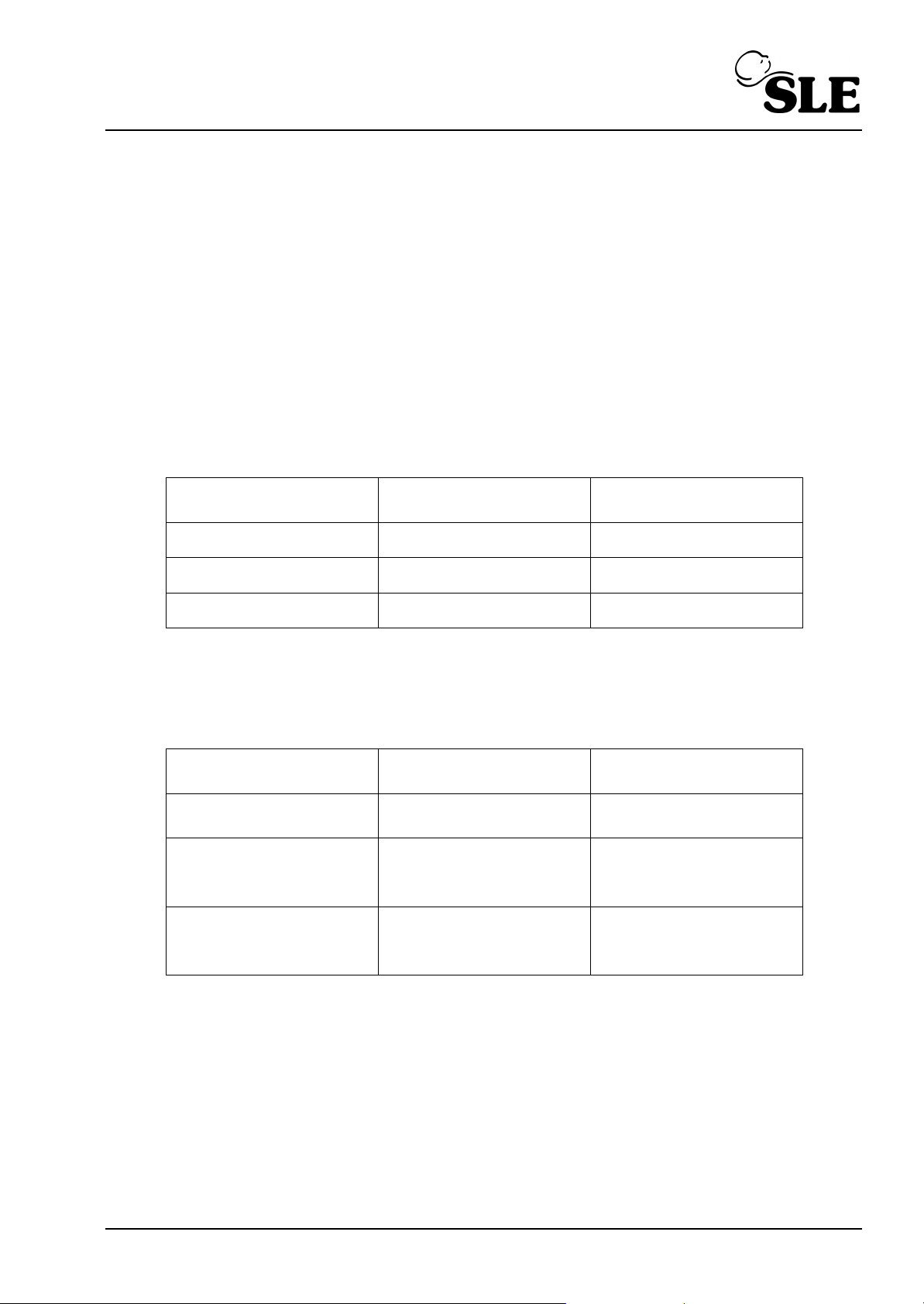
Pins on PLB Voltage
Lower Limit
PLB 32b 5.11V 5.13V
PLB 22b 12.0V 14.0V
PLB 6b 50V 60V
Confirm that all the voltages are within the limits.
Set the inspiratory time control to 3 seconds and set the waveshape switch to the square
position.
Monitor the voltage at the cathode of D5
Voltage Monitoring
Condition
manual breath not
pressed
Waveshape switch set
to taper position and
manual breath pressed
Waveshape switch set
to square position and
manual breath pressed
Voltage
Lower Limit
50V 60V
22V 28V
25V 35V
Voltage
Upper Limit
Voltage
Upper Limit
Confirm that the voltages are within the limits.
(SLE2000) Page 51
Page 52

13.1.1 System Watchdog
Note: This control is factory set and shold not normally require adjustment on
service.
Monitor U8 pin 8 on A0702 board. By adjusting RV10 ascertain the two points where the
voltage falls from 5.12V to 0V, then set RV10 to midway between these positions, and
ensure that the voltage on U3 pin 11 is a continuous 5.12V
13.1.2 Pressure Transducer, PTR1 Calibration.
With PTR1 open to atmosphere, monitor the DC voltage on pin 26 of (U18).
Adjust RV2 to set the voltage to 1.00V 10mV.
Then, using the pressure analyser for reference, apply a pressure of 40cmH
O 0.1 cmH2O
2
to PTR1, P2.
Adjust RV5 to give 3.40V 10mV.
Repeat this procedure until both voltages are correct to within 10mV for their respective
pressures.
13.1.3 Pressure Transducer Buffered Output
With PTR1 open to atmosphere, monitor the voltage on PLB 23b and adjust RV3 to give
1.00V 10mV.
Then, using the pressure analyser for reference, apply a pressure of 50cmH
O 0.1 cmH2O
2
to PTR1, P2.
Adjust RV4 to give 6.00V 10mV.
Repeat this procedure until both voltages are correct to within 10mV for their respective
pressures.
13.1.4 CPAP alarm threshold control.
Monitor the voltage on U18 pin 27.
Then, with the CPAP alarm control turned fully ACW, slowly rotate the control CW until the
voltage just exceeds 0V and is no more than 50mV.
Then release the collet on the control knob and re-position it so that the pointer points to
-5cmH2O.
Tighten the collet and rotate the control to point to 15 cmH2O and adjust RV9 to give 1.20V
10mV.
Repeat adjustment if necessary.
Page 52 (SLE2000)
Page 53

13.1.5 PIP alarm threshold control.
Monitor the voltage on U18 pin 2.
Then, with the PIP alarm control turned fully ACW, slowly rotate the control CW until the
voltage is 0.300 5mV.
Release the collet on the control knob and re-position to point to 10 cmH2O.
Tighten the collet and rotate the control to point to 50cmH2O and adjust RV7 to give 2.70V
10mV.
Turn control back to 10cmH2O and check the voltage is 0.3V. Repeat adjustment if
necessary.
13.1.6 Inspiration Time Control
Rotate the inspiration time control fully CW and adjust RV6 to give a digital display of 3.00
seconds.
13.1.7 Alarm Volume Control
Note: This control is factory set and shold not normally require adjustment on
service.
Check that adjustment to RV1 varies the audible alarm volume, and then set RV1 to the
middle of its travel.
13.1.8 Airway Trigger Calibration (Part 1)
Note: This control is factory set and shold not normally require adjustment on
service.
Using a complete standard patient circuit (N2188) with a humidifier chamber and test lung
fitted, perform the following.
To set the expiratory time window, using a dual beam oscilloscope, connect one channel
to U200 pin 2 and invert the trace. Connect the other channel to U200 pin 4.
With the timebase set to 100ms/div and sensitivity set to 2V/div, set the ventilator to CMV,
60BPM, 0.5 sec insp. time.
This will produce two similar positive going waveforms. Adjust RV200 such that the interval between the two leading edges is 200ms 10ms.
Time between the two
leading edges
Time
Lower Limit
190ms 210ms
Time
Upper Limit
Confirm that the time is within the limits.
(SLE2000) Page 53
Page 54
13.2 Pneumatic module setup and calibration
13.2.1 Fresh Gas Pressure Regulator (REG3) Adjustment
Connect the ventilator to gas supplies at 4 bar and monitor the Fresh Gas Pressure
Regulator (REG3) output using the test point provided and adjust the regulator to provide
10psi.
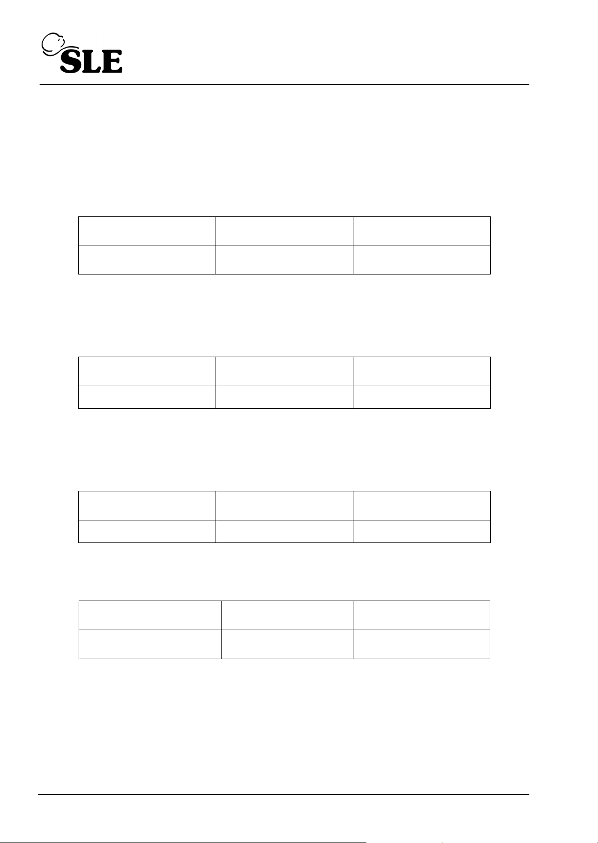
Pressure regulator
REG3 adjustment
Pressure
Lower Limit
9.5psi 10.5psi
Pressure
Upper Limit
Minimum blender flow needle valve (NV2) adjustment
Monitor the flow from NV2 at the outlet on the base of the pneumatic module. Ensure that
the oxygen cell is fitted securely and there are no leaks at its seating. Adjust the needle
valve NV2 to provide 7 lpm.
Flow
Lower Limit
Flow
Upper Limit
NV2 Flow adjustment 6.75 lpm 7.25 lpm
13.2.2 Fresh gas flow needle valve (NV1) adjustment
Monitor the flow from the Fresh gas port on the front panel and adjust the flow needle valve
NV1 to provide 5lpm.
Flow
Lower Limit
Flow
Upper Limit
NV1 Flow adjustment 4.75 lpm 5.25 lpm
Turn off the power to the ventilator and ensure the flow from the fresh gas port is within
limits.
Flow
Lower Limit
Fresh gas dump flow
confirmation
Page 54 (SLE2000)
0.70 lpm 1.50 lpm
Flow
Upper Limit
Page 55

13.2.3 Fresh Gas Block and Leak Alarm
Remove gas supplies from ventilator and connect DMM between pins 2 and 4 of PTR2.
Adjust RV500 to give a voltage of 0.00V 10mV.
With air and O2 connected to the pneumatic module and the blender set to 21%, monitor the
fresh gas flow and confirm that the flow is 5lpm 0.25lpm.
Using a variable flow restrictor and the pressure analyser for reference, create a pressure in
the fresh gas line of 15cmH2O 0.5 cmH2O.
Adjust RV501 so that the leak alarm and LED just trip on.
Using the flow restrictor, increase the pressure in the fresh gas line to 80cmH2O 1 cmH2O
and adjust RV502 until the block alarm and LED just trip on.
13.2.4 FiO2 Digital Display.
With both the air and O2 supplies at approx. 4 bar pressure, monitor the gas at the fresh gas
outlet with the oxygen analyser.
Set the O2 blender to 100% oxygen.
Remove the air supply and note the reading on the analyser.
Then adjust the calibration potentiometer on the rear panel of the electronic module so that
the FiO2 digital display agrees with the analyser reading to within 0.5 percentage points.
Note: This control is factory set and shold not normally require adjustment on
service.
Reconnect the air supply. Set the blender control to 21%, then remove the oxygen supply
and adjust RV101 on the A0703 PCB (Power supply board) until the digital display shows
21%.
Repeat both at 21% and 100% settings until both readings are within 1 percentage point.
Check the FiO2 display accuracy by setting the blender to achieve the following readings on
the O2 analyser and then checking that the FiO2 digital display on the electronic module is
within the limits.
(SLE2000) Page 55
Page 56
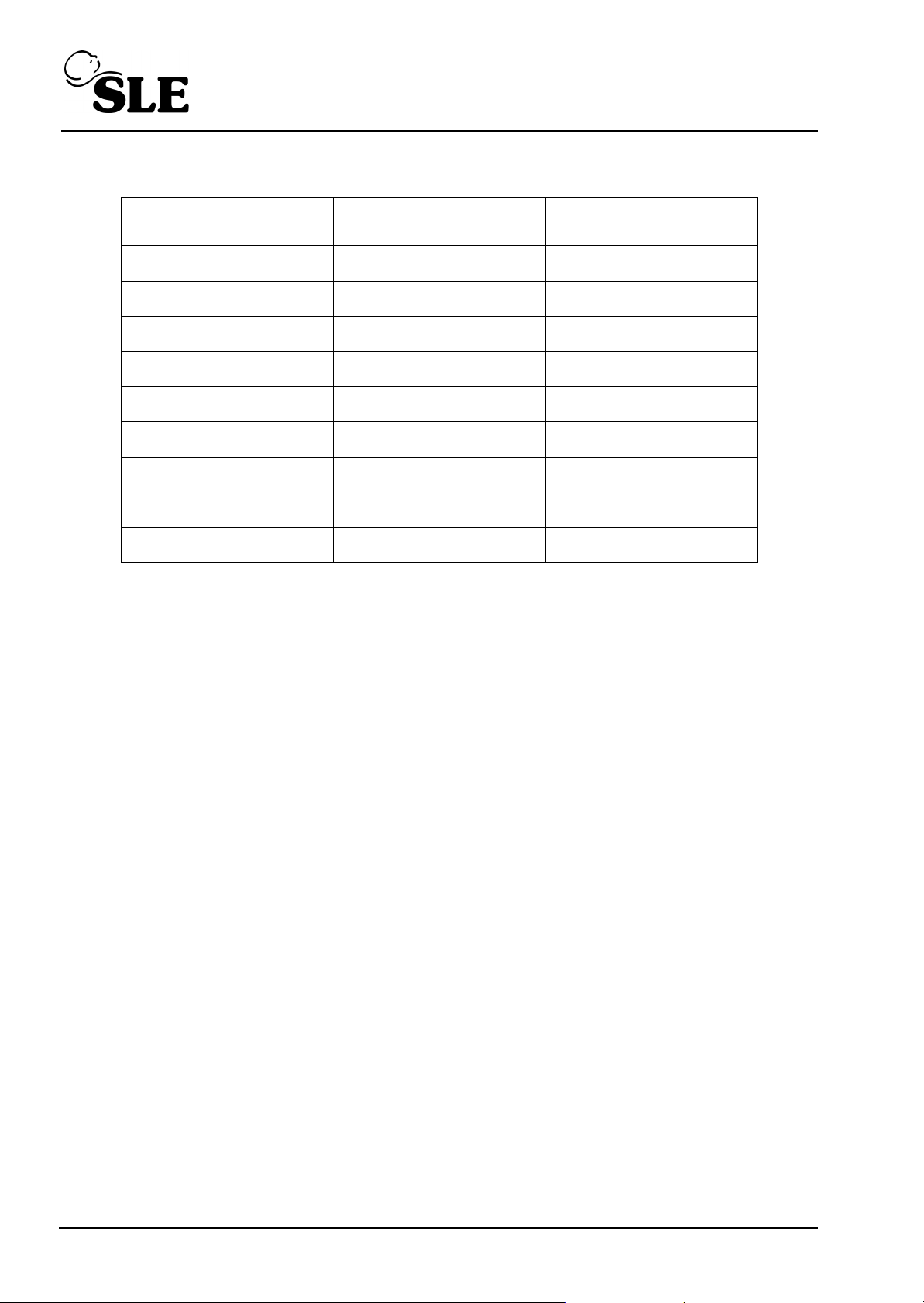
FiO2 Display Accuracy
O2 Analyser Reading FiO2 Display
Lower Limit
FiO2 Display
Upper Limit
21% 20% 22%
30% 29% 31%
40% 39% 41%
50% 49% 51%
60% 59% 61%
70% 69% 71%
80% 79% 81%
90% 89% 91%
100% 99% 101%
Confirm that the FiO2 display readings are within the limits.
13.2.5 Airway Trigger Calibration (Part 2)
Select a BPM rate of 1BPM and an inspiration time of 0.5 seconds, set PIP to 30 cmH2O
and with the CPAP regulator turned off completely and the alarm parameters set as follows
CPAP = 0 cmH2O, PIP = 30 cmH2O.
Switch the ventilator into PTV mode and set the PTV threshold control fully clockwise.
Fit a 2ml syringe into the tracheal port of the ET manifold.
Slowly draw 2ml of air from the tracheal port at an approximate rate of 2ml in 0.5 seconds.
If ventilator fails to trigger or falsely triggers, it will be necessary to adjust RV202 until the
desired response is achieved.
Remove the 2ml syringe and replace with the 10ml syringe.
Turn PTV threshold fully anti-clockwise, draw 10ml over 0.5 seconds and ensure that the
ventilator triggers on this inspiratory effort.
Confirm completion of the Airway Trigger Calibration
Page 56 (SLE2000)
Page 57

13.3 Soak Test
Connect the both ventilator gas supplies to air.
Connect a full patient circuit and occlude the ET manifold.
13.4 CMV mode soak test 50 hours
Set the following:
• Set mode switch to CMV setting.
• BPM control to 125.
• Insp. Time. Control to 0.24
• Low CPAP alarm to minimum -5 position.
• Insp pressure regulator to 45cm H2O.
• Pressure display switch to Peak (MAX) 45cm H2O.
• Pressure wave switch to taper position.
• CPAP/PEEP regulator to 10cm H2O (min) 15cm H2O (MAX). Check by setting the
pressure switch to min.
• Start soak test and record start, time and date.
• Run for 50 hours and ensure that there are no component failures.
(SLE2000) Page 57
Page 58

13.5 Functional testing (Post soak).
13.5.1 Perform Electrical Safety Test
Equipment under test is: SLE2000 Infant Ventilator Class 1B.
The electrical safety test must be carried out on the unit with all the electrical connections
intact. Ensure the mains switch on the ventilator is ON for the duration of these tests.
Check that:
a) Mains insulation resistance exceeds 50M
b) Leakage current is less that 150A
c) Earth resistance on all exposed metal parts is less that 0.2
d) Check the resistance to earth on the internal metal screening is less than 0.2.
4.0.1 Basic Operation
With mains power connected, switch unit on and observe that:
• All audible alarms sound for approximately 2 seconds
• All warning LED’s except ‘BLOCK’ are activated for approximately 2 seconds
• All 7 Segment displays increment from 0 to 9 (Check all segments are operative)
• With mode switch set successively in CPAP, CMV, PTV, and SIMV, disconnect the
mains supply & confirm that the Mains Failure audible alarm is activated in each
position.
Select CPAP mode
• Check operation of MANUAL BREATH push-button, and by adjustment of INSP TIME
CONTROL confirm that a range of inspiratory times from 0.1 sec. to 3.0 sec. may be
obtained with the BPM keyswitch in the 1-125 position and 0.01 to 0.3 sec. in 126-250
keyswitch position.
• Check that this adjustment can be monitored on the INSP TIME display.
• Check that no mandatory breaths are present other than those produced by the
MANUAL BREATH push-button.
• By selecting a range of inspiratory pressures from 0 Cm H2O to 60 Cm H2O in 10 Cm
H2O steps, ensure accuracy of digitally displayed pressure to less than 1 Cm H2O error
and proximal airway pressure gauge to less than 2 Cm error against the calibration
analyser.
• By setting the CPAP alarm control from 0 Cm H2O to 15 Cm H2O in 5 Cm H2O steps,
and adjusting the CPAP pressure regulator to an airway pressure 1 Cm H2O below the
alarm setting, check that the CPAP audible alarm and warning LED are activated in
each instance.
• With a CPAP alarm condition present, check that on pressing the MUTE button, the
audible alarm is muted and the MUTE LED is activated for a period of one minute
unless cancelled by the RESET button.
• Check that the RESET button cancels the MUTE function and resets all latched
warning LED’s.
Page 58 (SLE2000)
Page 59

Select CMV Mode
• With the BPM keyswitch in the 1-125 position confirm that by adjustment of the BPM
control a range of BPM rates from 1 to 125 may be obtained and visually monitored on
the BPM display. With keyswitch in 126-250 position confirm BPM rates 126-250 are
obtained.
• With the BPM control set to 30, vary the INSP TIME control from 0.26 to 2.38 and
confirm that a range of I:E ratios from 1:6.7 to 9.9:1 can be obtained and visually
monitored on the I:E display.
• On setting the PIP alarm control from 10 Cm H
• Adjust the PIP pressure regulator to an airway pressure 4-5 Cm H
O to 60 Cm H2O in 10 Cm H2O steps;
2
O below the PIP
2
alarm setting, and confirm that the FAIL TO CYCLE audible alarm and warning LED
are activated.
• Adjust the PIP pressure regulator to an airway pressure 4-5 Cm H2O above the PIP
alarm setting, and confirm that the HIGH PRESSURE audible alarm and warning LED
are activated and that the fresh gas dump solenoid valve is de-energised (leak alarm is
activated).
• Also check that when the fresh gas solenoid is de-energised, 0V is present at pin 4 of
the rear panel auxiliary output connector (7 pin DIN). Check that this changes to 5V
when the solenoid is energised.
• Verify operation and visual LED indication of MAX/MEAN/MIN pressure display switch.
• By monitoring the patient airway pressure wave shape using an oscilloscope, verify
that the rising edge may be modified from fast rise to slow rise by the appropriate
settings of the PRESSURE WAVE switch when in 1-125 BPM mode.
• Check that the pressure wave rising edge is always fast when in the 126-250 BPM
mode, irrespective of the PRESSURE WAVE switch setting.
Select PTV Mode
• Check operation of the PTV trigger system. Ensure correct operation of the TRIGGER
SENSITIVITY control.
• Check that the trigger back-up system works properly and that the back-up audible
beep and LED are activated when a back-up breath is initialised.
Select SIMV Mode
• Check operation of the SIMV trigger system, ensuring that back-up audible beep is
activated during machine initialised breaths.
(SLE2000) Page 59
Page 60

Pressure Controls
• Check that the CPAP pressure regulator can be set to produce at least 15 Cm H2O
airway pressure in its fully clockwise position.
• Check that the PIP pressure regulator can be set to produce up to 62 Cm H2O
inspiratory airway pressure in its fully clockwise position.
• Check that INSPIRATORY pressures are in accord with decal markings for 20, 40 and
60 Cm H2O.
4.0.2 Mains Voltage tolerance test.
• This final test will check for the operation of the ventilator at a reduced mains voltage.
• Connect the ventilator to the mains via a variable transformer (variac) so the mains
voltage can be varied with the ventilator set up as follows:-
Mode set to CMV;
BPM set to 125;
Insp time set to 0.24 secs;
Pressure set to 30 over 0 cmH2O ;
Slow rise selected.
Clear all alarms conditions.
• Reduce the mains voltage by 17% of its nominal value and ensure that normal
operation is maintained particularly with regard to the solenoid valves and the displays.
Nominal mains voltage Reduce to:
230V 191V
110V 91V
100V 83V
Page 60 (SLE2000)
Page 61

TroubleShooting
(SLE2000) Page 61
Page 62

4.1 SLE 2000 Electrical Troubleshooting Chart
PROBLEM
1. When unit is switched ON,
POWER light is not illuminated, battery fail alarm
sounds continuously.
2. SYSTEM FAIL alarm will not
cancel
POSSIBLE CAUSE REMEDY
a) No A.C power
b) No A.C power to transformer
Check wall sockets.
Check: fuses
mains filter
on-off switch
c) No secondary voltages (45V
rms & 10V rms)
Check for short circuits, otherwise change transformer
d) No DC voltages from PSU
PCB (60V, 12V, & 5.12V)
Check for short circuits, otherwise replace A0703/01 PCB
e) Fault on processor PCB
and recalibrate.
Replace A0702/01 pcb and
recalibrate
Processor pcb faulty Replace A0702/01 PCB and
recalibrate
3. HELP message displayed
on digital readout
4. SOL message displayed on
digital readout
5. Ventilator powers up, but
does not cycle in CMV
mode and no audible or
visual alarms.
Open circuit analogue inputs to
processor
a) Faulty or open circuit sole-
noid
b) faulty wave shape switch
c) Faulty BPM range switch
d) Faulty power supply
e) Harness fault
Check for 5.12V dc on pin PLB
32b of PCB A0702/01
Check operation of potentiometers and wiring harness connections
Check operation of solenoid
and replace if necessary
Replace
Replace
Refer to 1d
Refer to circuit diagram and
check integrity of harness connections
If voltage absent refer to 1d
Page 62 (SLE2000)
Page 63

4.2 SLE 2000 Pneumatic Troubleshooting Chart
Sympton Possible Cause Remedy
Blender:
Audible Alarm when Air &
O2 supplies are
1. Air/O2 differential
pressure exceeds 20PSI
connected
2. Jammed Alarm
% O
error exceeds ±3% 1. Digital FIO2 reading
2
requires adjustment.
Block/Leak Alarm:
Leak alarm when patient
1. No Air/O
circuit is connected.
2. Excessive PIP.
3. Leak in patient circuit.
4. Fault is fresh gas supply.
supply.
2
Ensure Air/O2 differential
pressure is less than 20PSI
Disconnected Air & O2
supplies and reconnect. If
fault persists, reject blender.
Check % O2 with suitable
calibration reference. Adjust
digital readout as
appropriate. If fault persists,
reject blender.
Connect supply gas as
appropriate.
Adjust PIP alarm threshold
or PIP regulator and press
reset.
Check humidifier for leaks.
Check restrictor is in correct
position.
With reset button held in,
occlude fresh gas port. If
BLOCK alarm does not
replace LEAK alarm, contact
qualified Service Engineer.
Block alarm 1. Blockage in fresh gas
Replace patient circuit.
supply.
Low Peak Inspiration
Pressure
(SLE2000) Page 63
1. Low Air/O2 supply
pressures.
Ensure Air/O2 supply = 4
Bar.
Page 64
2. PIP alarm threshold too
low.
3. Fault in patient circuit.
4. Exhalation block not
properly located.
5. Blocked Inspiratory
nozzle.
6. Faulty PIP regulator
Adjust PIP alarm threshold.
Replace patient circuit.
Relocate exhalation block.
Refer to qualified Service
Engineer
Refer to qualified Service
Engineer
CPAP Desired CPAP pressure
As for PIP (see above).
cannot be achieved.
Excessive residual PEEP Faulty Patient circuit. Replace patient circuit
Page 64 (SLE2000)
Page 65

Technical Specification
(SLE2000) Page 65
Page 66

5. Technical Specification
5.1 Conventional Ventilation
Modes: CPAP,CMV,PTV,SIMV
BPM Ranges: 1-125 or 126 - 250 breaths per minute (1BPM STEPS)
selected via rear security key switch
Inspiratory Time: 0.1-3.0 or 0.01-0.3 seconds
I:E Range : 9.9:1 - 1:9.9 calculated from BPM and INSP. TIME
settings.
CPAP Pressure: 0 cmH2O to 15 cmH2O minimum.
Inspiratory Pressure: 0 cmH2O to 60 cmH2O
switched fast or slow rise waveforms.
5.2 Displays
Proximal Airway Pressure Gauge Gauge range -6 to +60 cmH2O
Seven segment LED’s: showing BPM, INSP. TIME, I:E RATIO, FIO2
and PRESSURE (max., mean or min.).
Indicator LEDs: POWER: green LED indicates power on.
SYSTEM FAIL: Indicates main processor
system fail.
TRIGGER BACK-UP: Indicates a machine
delivered breath if patient fails to trigger
ventilator during back-up time window.
MAX., MEAN, MIN.: indicates which value is
being displayed on the 7 segment pressure
display.
MUTE: Indicates that the mute function is
active.
Alarm LED’s LOW CPAP : warning of the pressure dropping
below the LOW CPAP alarm limit
CYCLE FAIL: warning that no breath has been
detected. Ventilator breath is below alarm
threshold.
HIGH: warning of the PIP alarm limit being
exceeded
BLOCK: warning of a block in the fresh gas
supply limb of patient circuit.
LEAK : warning of a leak in the fresh gas
supply limb of the patient circuit.
Page 66 (SLE2000)
Page 67

Driving Pressure Gauge:
(Scaled for resultant inspiratory
pressures above PEEP)
Gauge range :0-60 cmH2O plus PEEP level
5.3 Controls
Ventilation mode switch: OFF, ALARM TEST/CPAP, CMV, PTV, SIMV
BPM Control (ten turn): either 1-125BPM or 126-250BPM
INSP. TIME Control (ten turn): either 0.10-3.00 seconds (min exp time: 0.25
seconds) or 0.01-0.3 seconds (min exp time:
0.12)
Pressure Display Switch: MAX., MEAN, MIN.
Pressure Wave Switch: Slow or Fast rise
Manual Breath Pushbutton
Alarm Mute and Reset
Pushbuttons:
Trigger Sensitivity Control: Range: 2ml/0.5 sec max. To 10ml/0.5sec min.
Pressure alarm setting controls: LOW CPAP: -5 to 15cmH2O
Pressure controls: INSPIRATORY
Air/Oxygen Blender Control 21-100% ± 3%
Mute active for 60 seconds (approx.)
Using SLE N2188 patient circuit.
PIP :10 to 60 cmH2O
CPAP/PEEP
5.4 Alarms
Audible only:
Loss of mains supply: Battery powered alarm
Loss of Air or O2 supply: Blender alarm.
Audible and Visual:
HIGH CIRCUIT PRESSURE
CYCLE FAIL
LOW CIRCUIT PRESSURE
FRESH GAS BLOCK
FRESH GAS LEAK or TOTAL GAS SUPPLY FAIL
SYSTEM FAIL: FAIL.
(SLE2000) Page 67
Page 68

5.5 Power , Dimensions etc.
Voltage : 100-120V/ 50-60 Hz
220-250V/ 50-60 Hz
Power : 120 VA
Fuses : 220-250V~50-60 Hz : Fuse T 1.0A
100-120V~50-60 Hz : Fuse T 2.0A
Air and O2 :4 bar
Operating Environment: Temp: 10-40°C
Humidity: 0-90% (non condensing)
Size, Ventilator only : 37 cms W × 31 cms H × 32 cms D
Height on pole: 137 cms
Weight Ventilator Only: 10 Kgs
Complies with: CE DECLARATION OF CONFORMITY
IEC 601-1 and 601-2-12 1988
BS 5724 Part 1 and section 2.12.1990
EMC Medical device 601-1-2
Patient Circuit Required: Model : N2188 Single use. or variant
Model : N2200 Re-usable. or variant
Transport and storage conditions Temperature -20 to 50“C for not longer than 2.5
months
Humidity 15 to 90% (non condensing) for not
longer than 2.5 months
Atmospheric pressure 500 to 1060hPa for not
longer than 2.5 months
Protection Class 1 Type B Protection against electric
Shock
Mode of operation Continuous
Page 68 (SLE2000)
Page 69

Circuit Details
(SLE2000) Page 69
Page 70
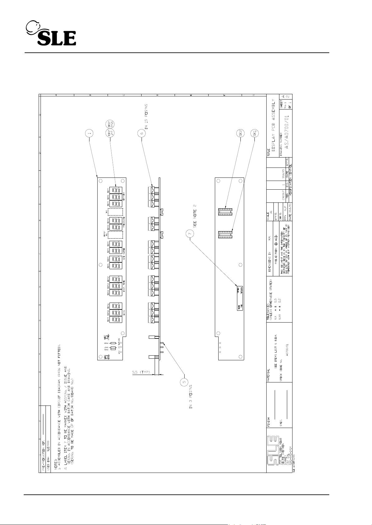
6. Electronic Circuit Details
6.1 Display Board A0700/01
Page 70 (SLE2000)
Page 71
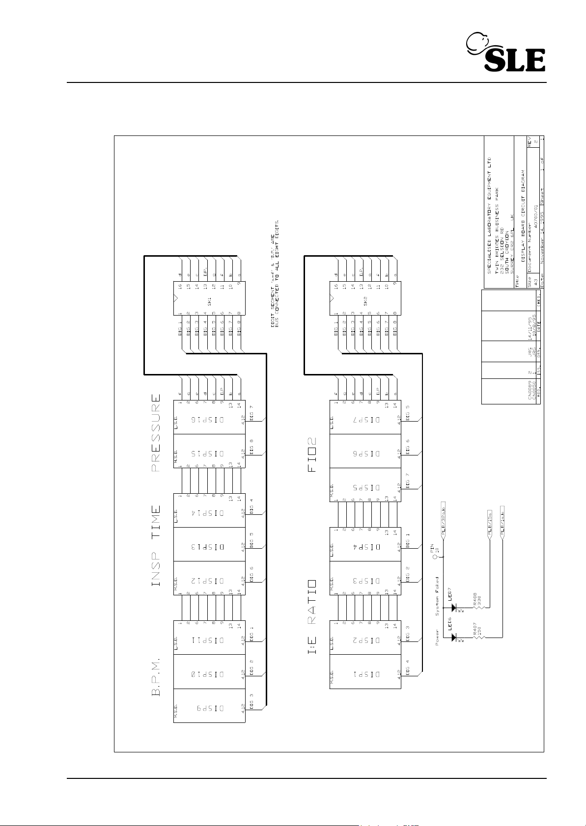
6.1.1 Display Board Circuit Diagram A0700/01
(SLE2000) Page 71
Page 72
PARTS LIST
Finished Item Stock Number A0700/01
Finished Item Description Display PCB Assembly
Drawing Number AS/A0700/01 Issue 2
Part Number Component Description Qty Used Component Reference(s)
J0700 Display Board blank 1 ITEM 1 (PCB)
D0308 LED Green Rectangular LGB480EH 1 LED 6
D0546 LED Red Rectangular LSB480EH 1 LED 7
D0590 Display 7 Segment MAN4640A 15 DISP 1-7, DISP 9-16.
M0307 Terminal Pin(Pcb single sided) 3 ITEM 5
R0424 330R Resistor 1% 0.25W SMA0207 1 R408
R0416 150R Resistor 1% 0.25W SMA0207 1 R407
S0212 IC Socket 16 way DIL 2 SK1 & SK2
S0445 Socket 14 way DIL 15 ITEM 6
M0718 Label, PCB Identification 1 ITEM 7
Page 72 (SLE2000)
Page 73
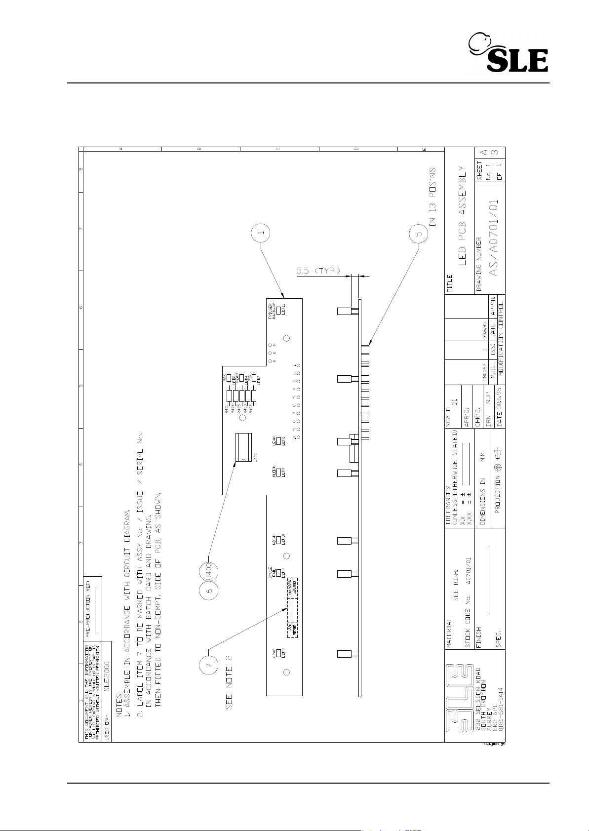
6.2 LED Board A0701/01
(SLE2000) Page 73
Page 74
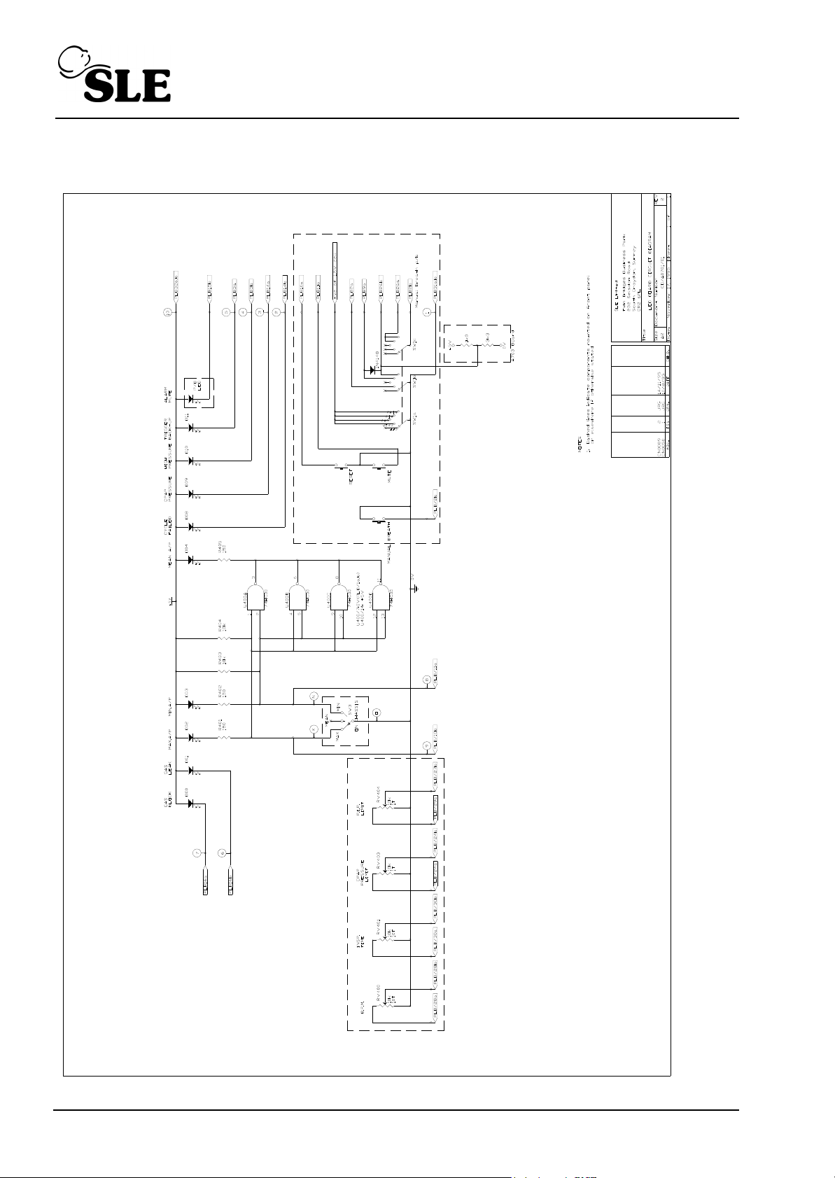
6.2.1 LED Circuit Board Diagram CD/A0701/01
Page 74 (SLE2000)
Page 75
PARTS LIST
Finished Item Stock Number A0701/01
Finished Item Description LED PCB Assembly
Drawing Number AS/A0701/01 Issue 1
Part Number Component Description Qty Used Component Reference(s)
J0701 LED pcb blank 1 ITEM 1 (PCB)
D0308 LED Green Rectangular LGB480EH 3 LED2,3,4
D0508 74HC00 1 U400
D0546 LED Red Rectangular LSB480EH 6 LED 0,1,8,9,10,11
M0307 Terminal Pin(Pcb single sided) 13 ITEM 5
R0463 10K Resistor 1% 0.25W SMA0207 2 R403,404
R0416 150R Resistor 1% 0.25W SMA0207 3 R401, 402, 405
S0242 IC Socket 14 way DIL 1 ITEM 6 (U400)
M0718 Label, PCB Identification 1 ITEM 7
(SLE2000) Page 75
Page 76

CPU Board AS/A0702/01
AS/A0702/01 Issue 4: Standard board (See board drawing AS/A0702/01 issue 4 on
page 77 and circuit diagram CD/A0702/01 issue 2 on page 78).
Stabilization of leak alarm trigger threshold
AS/A0702/01 Issue 5: Addition of capacitor C0481 to stabilize leak alarm trigger
threshold (See board drawing AS/A0702/01 issue 5 on page 84
and circuit diagram CD/A0702/01 issue 6 on page 85).
Also see service information “SI 000201 Leak Alarm Trigger Threshold.” on page 162.
Alarm sounder failing to operate in fresh gas blocked alarm conditions
AS/A0702/01 Issue 5: No change. Reference of modification see Detail A on page 90.
CD/A0702/01 Issue 7: Modification of circuit diagram to show track cut between C500 to
U500 pin 7, Connection of link between C500 and U500 pin 8 and
connection of a 68M resistor across pin 5 and 7.
(See board drawing AS/A0702/01 issue 5 on page 89 and circuit diagram CD/A0702/01
issue 6 on page 91).
Page 76 (SLE2000)
Page 77
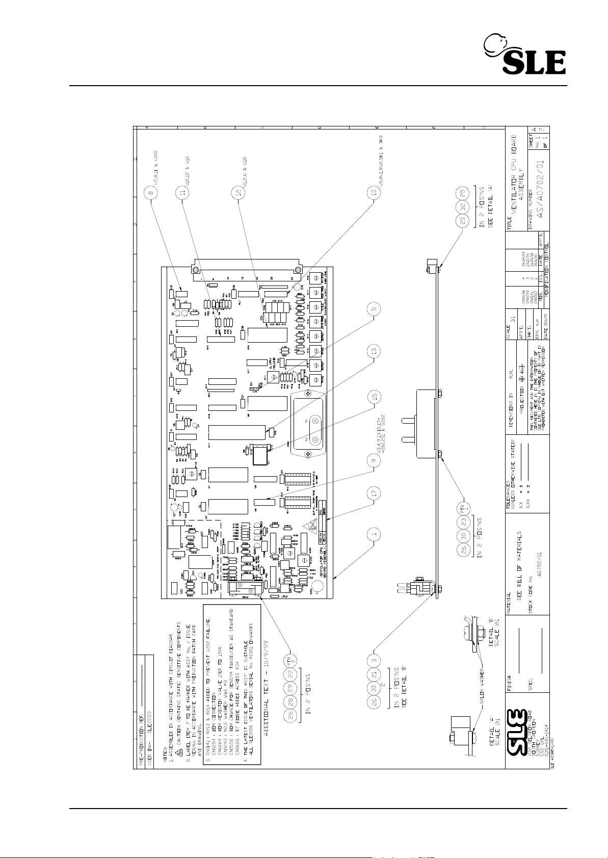
6.3 Ventilator CPU Board AS/A0702/01 Issue 4
(SLE2000) Page 77
Page 78
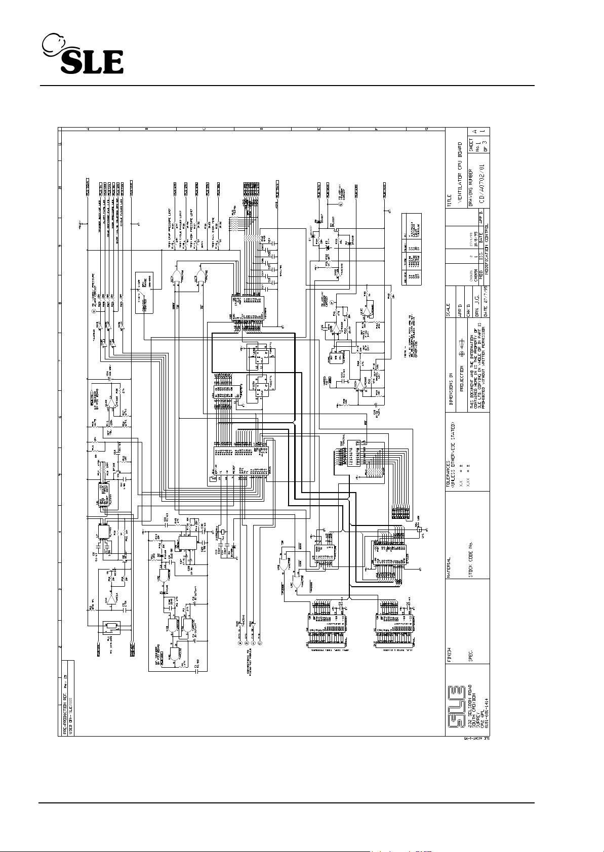
6.3.1 Ventilator CPU Board CD/A0702/01 Issue 2 Sheet 1 of 3
A3 version on page 145 of circuit diagram appendix.
Page 78 (SLE2000)
Page 79
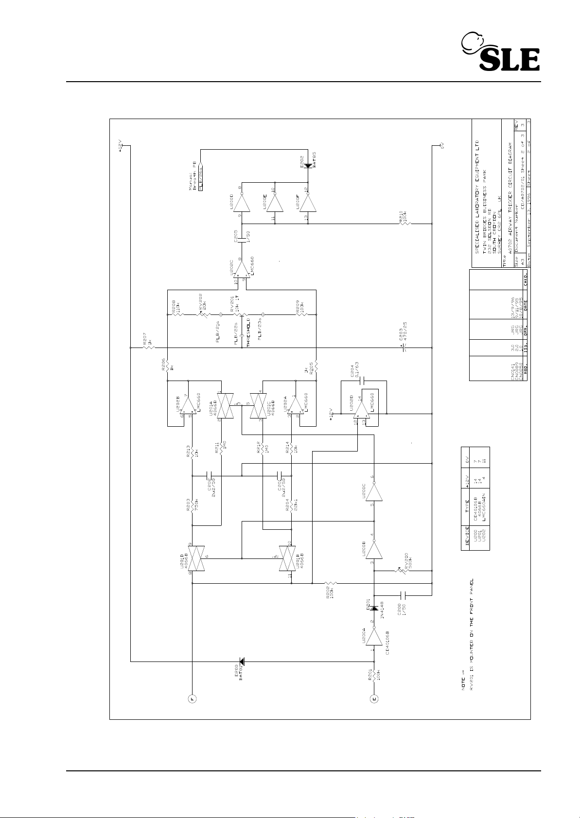
6.3.2 Airway Trigger Circuit Diagram CD/A0702/01 Sheet 2 of 3
(SLE2000) Page 79
Page 80
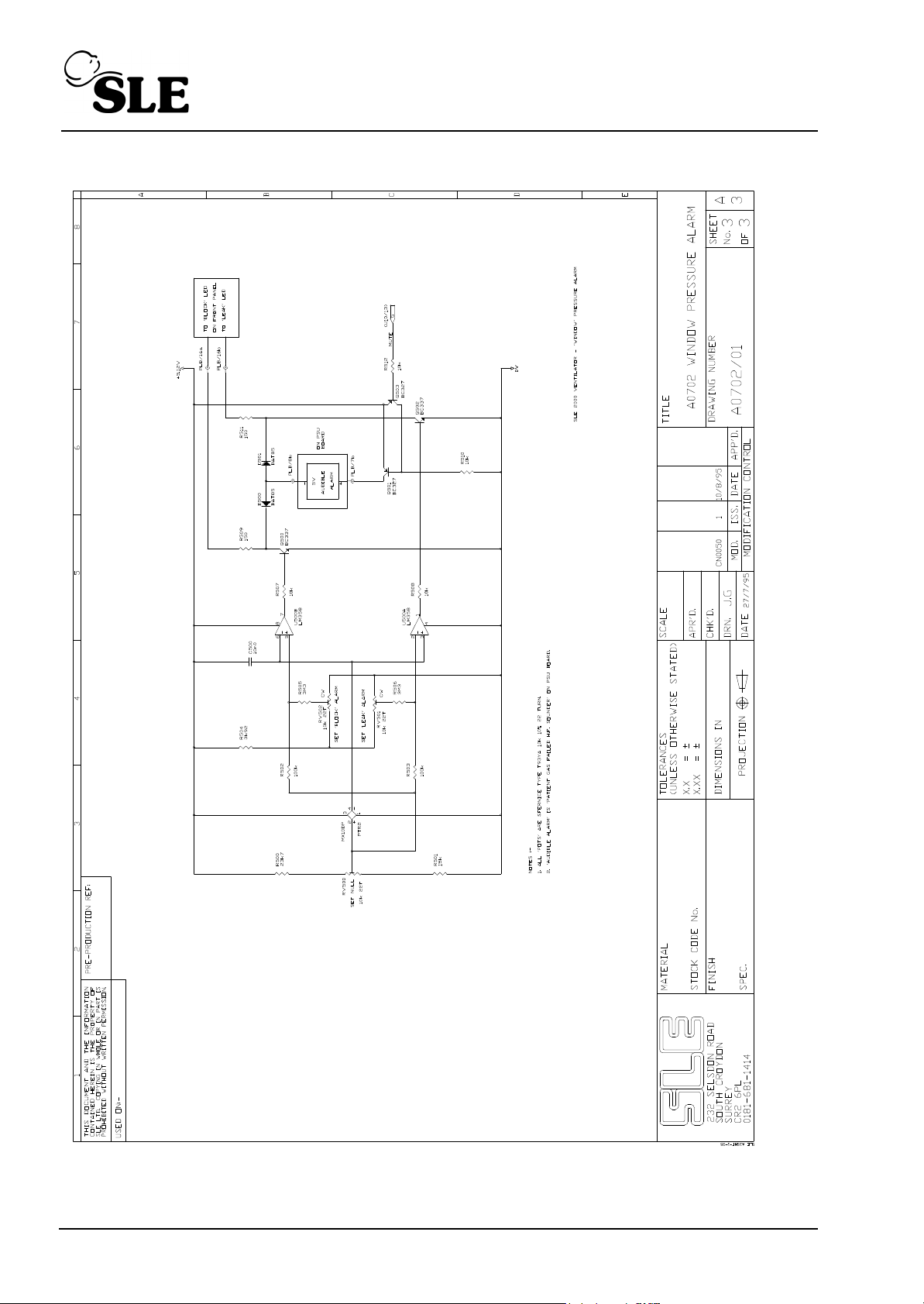
6.3.3 Window Pressure Alarm A0702/01 Sheet 3 of 3
Page 80 (SLE2000)
Page 81

PARTS LIST
Finished Item Stock Number A0702/01
Finished Item Description Ventilator CPU PCB Assembly
Drawing Number AS/A0702/01 Issue 4
Part Number Component Description Qty Used Component Reference(s)
J0702 Ventilator CPU pcb blank 1.00 Each ITEM 1 (PCB Rev D)
Check pressure transducer type (ITEM PTR2) and read note for component pre-fix.
C0256 47uF Capacitor 16V 10-20% Tan. 1.00 Each C27
C0260 10nF Capacitor 63V 20% MXS2 4.00 Each C12,C26,C32 & C500
C0434 10u Capacitor 35V 20% 5mm Lead 4.00 Each C4,C6,C15 & C28
C0439 100u Capacitor 25V 20% Elect. 1.00 Each C16
C0441 470uF Capacitor 25V 20% 1.00 Each C203
C0450 0.1uF Capacitor 63V 10% MKS2 18.00 Each C1-3,8,30,31,C33-43 &
C204
C0459 2.2uF Capacitor 50V 10% 3.00 Each C9,C201 & & C202
C0461 33pF Capacitor 100V 10% Ceram. 2.00 Each C13 & & C14
C0462 luF Capacitor 50/63V 10% MKS2 14.00 Each C5,7,11,C17-24,C29,C200
&C205
D0284 BZX79C4V7 (was BZY88C 4v7) 1.00 Each D3
D0288 LM358N 1.00 Each U500=Pt No.D0586 when
pre-fix is not 'S' for PTR2
D0298 ICM7218DlJ1 28 Pin Harris 2 00 Each U1 & U2
D0305 ADC0809CCN NSC 1.00 Each U18
D0320 74HC132N 1.00 Each U3
D0336 BC337 4.00 Each Q1,Q2,Q500 & Q502
D0402 lN4007 Plastic Diode 2.00 Each D5 & D7 (CN0626)
D0406 1N4148 4.00 Each D1,D2,D4 & & D201
D0407 BAT85 4.00 Each D6.D202.D500.D501
D0513 74HC14 1.00 Each U4
D0525 4066 Quad Bilaterial Switch 1.00 Each U201
D0566 TL7705ACP 1.00 Each U7
D0569 BAT81 1.00 Each D200
D0570 Crystal 11.0592 MHz 1.00 Each XL1
D0571 74HCT138N 1.00 Each U5
D0572 74HCT32N 1.00 Each U9
D0573 74HCT74N 1.00 Each U15
D0574 74HCT573N 1.00 Each U16
D0575 74HCT02N 1.00 Each U17
D0576/01 27C128-20/P 1.00 Each U6
D0577 LM567CN 1.00 Each U8
D0578 74AC540 1.00 Each U10
(SLE2000) Page 81
Page 82

Part Number Component Description Qty Used Component Reference(s)
D0579 74HC541 1.00 Each U12
D0580 TLCSSSCP 1.00 Each U11
D0581 LMC660AIN 2.00 Each U13 & & U202
D0582 80C31P (Phillips) 1.00 Each U14
D0584 CD40106BE 1.00 Each U200
D0585 BC327 2.00 Each Q501 & Q503
D0636 IRLU110 power MOSFET,TO-251 1.00 Each Q4
D0638 ZTX450 1.00 Each Q3
M0626 Jumper Link 1.00 Each ITEM 5
M0660 Pad Adhesive double sided 1.00 Each ITEM 15
M0692 Transistor Pad T05 1.00 Each
M0718 Label, PCB Identification 1.00 Each ITEM 17
N2113 Pressure Transducer 142SCOlD 1.00 Each PTR1
N2176 Sensor SXOlDN (Sensym only) 1.00 Each PTR2
If N2176 is not Pre-Fixed with M on component then R501 becomes 33K(PT No.R0473) & U500
becomes LM358(PT No.D0288)
00227 Relay W172DIP-5 5V DC 1.00 Each RL1
P0230 DIN41612 64 Way 90 deg Plug 1.00 Each PLB
P0464 12way P.C.B Header Straight 0.25 Each
R0224 30K Resistor 0.25W 18 0 00 Each replaced by R0549 CN626
R0226 110K Resistor 1% 0.25W 1.00 Each R208
R0349 24K Resistor 0.25W 1% 2.00 Each R24 & & R39
R0350 1K x 8 Resistor Network 1.00 Each RU2
R0351 10K x 8 Resistor Network 1.00 Each RU1
R0416 150R Resistor 1% 0.25W SMA0207 7.00 Each R25-R29,R509 & R511
R0428 470R Resistor 1% 0.25W 1.00 Each R41
R0436 1.0K Resistor 1% 0.25W SMA0207 6.00 Each R12,R30,R31,R205-R207
R0445 2K49 Resistor 1% 0.25W SMA0207 1.00 Each R23
R0446 2.7K Resistor 1% 0.25W 0.00 Each replaced by R0461CN0626
R0449 3.32K Resistor 1% 0.25W SMA 2.00 Each R35 & & R37
R0451 3.92K Resistor 1% 0.25W SMA020 2.00 Each R38 & & R504
R0454 4.75K Resistor 1% 0.25W 1.00 Each R15
R0456 5.6K Resistor 1% 0.25W SMA0207 1.00 Each R21
R0461 8.2K Resistor 1% 0.25W 1.00 Each R32
R0462 9.09K Resistor 1% 0.25W SMA020 1.00 Each R36
R0463 10K Resistor 1% 0.25W SMA0207 10.00 Each R18,19,33,40,42,43,507,50
R0467 15K Resistor 1% 0.25W SMA0207 1.00 Each R44
R0469 22.1K Resistor 1% 0.25W SMA020 1.00 Each R204
R0470 23.7K Resistor 1% 0.25W 1.00 Each R500
LKl (3 PIN SECTION)
8,510 & R512
Page 82 (SLE2000)
Page 83

Part Number Component Description Qty Used Component Reference(s)
R0471 27K Resistor 1k 0.25W SMA0207 3.00 Each R16,R17 & R20
R0473 33K Resistor 1% 0.25W 1.00 Each R501=Pt No.R0467when
pre-fix is not 'S' for PTR2
R0479 47K Resistor 1% 0.25W SMA0207 5.00 Each R1,R3,R4,R22 & R45
R0486 100K Resistor 1% 0.25W SMA0207 7.00 Each R13,R201,202,209
,210,502,R503
R0496 470K Resistor 1% 0.25W SMA0207 1.00 Each R14
R0499 750K Resistor 1% 0.25W 1.00 Each R203
R0501 1.0M Resistor 1% 0.25W SMA0207 2.00 Each R211 & R212
R0504 2.2M Resistor 16 0.25W 1.00 Each R2
R0506 3.3M Resistor 1% 0.25W SMA0207 3.00 Each Rll,R505 & R506
R0549 91K Resistor 1% 0.25w 1.00 Each R34
R0555 470K x 8 Resistor Network 1.00 Each RU3
R0556 10K x 8 Resistor Network 1.00 Each RU4
R0571 10k Resistor 1% 0.125W M/Film 2.00 Each R213 & R214
S0209 IC Socket 28 way DIL 4.00 Each ITEM 12
S0212 IC Socket 16 way DIL 5.00 Each ITEM 10 (U5,RU1,2,SKl &
SK2)
S0227 IC Socket 40 way DIL 1.00 Each ITEM 13
S0237 IC Socket 20 way DIL 3.00 Each ITEM 11
S0241 IC Socket 8 way DIL 4.00 Each ITEM 8 (U7,8,11& U500 )
S0242 IC Socket 14 way DIL 9.00 Each
T0205 Alarm Transducer Bracket 1.00 Each ITEM 3
V0404 5.0K Trimmer,cermet,top adjust 3.00 Each RV6-RV8
V0405 10K Trimmer, cermet, top adj 5.00 Each RV2-RV5 & RV10
V0406 20K Trimmer cermet,top adjust 2.00 Each RV9,RV202
V0408 100K Trimmer, cermet, top adj 1.00 Each RV1
V0410 500K Trimmer 1.00 Each RV200
V0414 10K Trimmer, cermet, top adj 3.00 Each RV500-RV502
H3116 M3 x 16 Pan Hd Pozi s.st 2.00 Each ITEM 22
H3108 M3 x 8 Pan Hd Pozi s.st 2.00 Each ITEM 21
H3225 M3 x 25 Csk Hd Pozi s.st 2.00 Each ITEM 23
H2312 M2.5 x 12 Pan Hd Pozi s.st 2.00 Each ITEM 20
H3091 M3 Nut Full s.st 6.00 Each ITEM 26
H2591 M2.5 Nut Full s.st 2.00 Each ITEM 25
H2595 M2.5 Plain Nylon Washer 2.00 Each ITEM 32
H3094 M3 S/Proof Washer s.st DIN6798 6.00 Each ITEM 28
H3095 M3 Plain Washer Nylon 6.00 Each ITEM 30
H3093 M3 Plain Washer B . st 2.00 Each ITEM 29
ITEM 9
(SLE2000) Page 83
Page 84
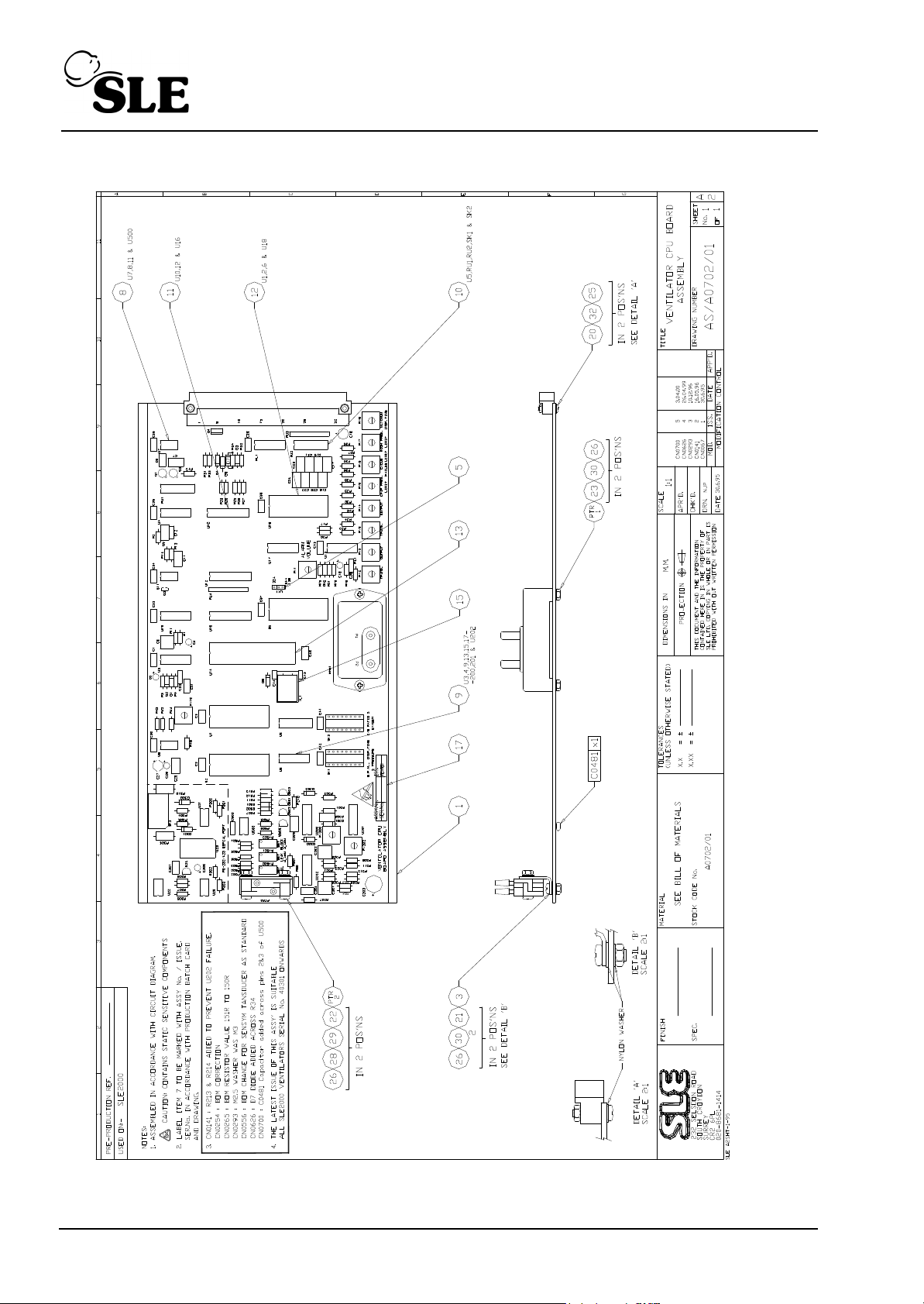
6.4 Ventilator CPU Board AS/A0702/01 Issue 5
Page 84 (SLE2000)
Page 85
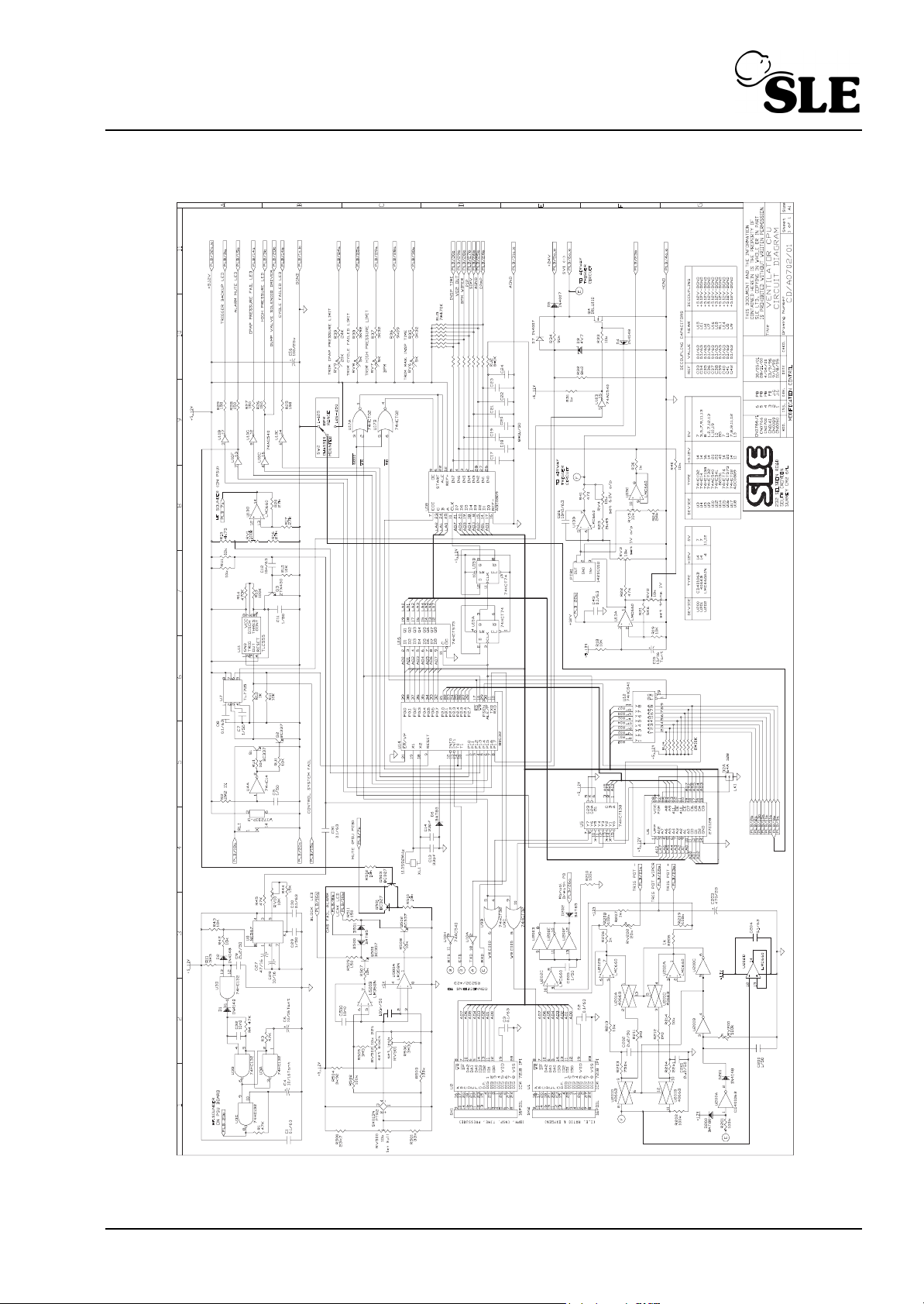
6.4.1 Ventilator CPU Board CD/A0702/01 Issue 6
A3 version on page 147 of circuit diagram appendix.
(SLE2000) Page 85
Page 86
PARTS LIST
Finished Item Stock Number A0702/01
Finished Item Description Ventilator CPU PCB Assembly
Drawing Number AS/A0702/01 Issue 5
Part Number Component Description Qty Used Component Reference(s)
J0702 Ventilator CPU pcb blank 1.00 Each ITEM 1 (PCB Rev D)
Check pressure transducer type (ITEM PTR2) and read note for component pre-fix.
C0256 47uF Capacitor 16V 10-20% Tan. 1.00 Each C27
C0260 10nF Capacitor 63V 20% MXS2 4.00 Each C12,C26,C32 & C500
C0434 10u Capacitor 35V 20% 5mm Lead 4.00 Each C4,C6,C15 & C28
C0439 100u Capacitor 25V 20% Elect. 1.00 Each C16
C0441 470uF Capacitor 25V 20% 1.00 Each C203
C0450 0.1uF Capacitor 63V 10% MKS2 18.00 Each C1-3,8,30,31,C33-43 &
C204
C0459 2.2uF Capacitor 50V 10% 3.00 Each C9,C201 & & C202
C0461 33pF Capacitor 100V 10% Ceram. 2.00 Each C13 & & C14
C0462 luF Capacitor 50/63V 10% MKS2 14.00 Each C5,7,11,C17-24,C29,C200
& C205
C0481 100nf Capacitor 50v 1.00 Each C2
D0284 BZX79C4V7 (was BZY88C 4v7) 1.00 Each D3
D0288 LM358N 1.00 Each U500=Pt No.D0586 when
pre-fix is not 'S' for PTR2
D0298 ICM7218DlJ1 28 Pin Harris 2 00 Each U1 & U2
D0305 ADC0809CCN NSC 1.00 Each U18
D0320 74HC132N 1.00 Each U3
D0336 BC337 4.00 Each Q1,Q2,Q500 & Q502
D0402 lN4007 Plastic Diode 2.00 Each D5 & D7 (CN0626)
D0406 1N4148 4.00 Each D1,D2,D4 & & D201
D0407 BAT85 4.00 Each D6.D202.D500.D501
D0513 74HC14 1.00 Each U4
D0525 4066 Quad Bilaterial Switch 1.00 Each U201
D0566 TL7705ACP 1.00 Each U7
D0569 BAT81 1.00 Each D200
D0570 Crystal 11.0592 MHz 1.00 Each XL1
D0571 74HCT138N 1.00 Each U5
D0572 74HCT32N 1.00 Each U9
D0573 74HCT74N 1.00 Each U15
D0574 74HCT573N 1.00 Each U16
D0575 74HCT02N 1.00 Each U17
D0576/01 27C128-20/P 1.00 Each U6
D0577 LM567CN 1.00 Each U8
Page 86 (SLE2000)
Page 87

Part Number Component Description Qty Used Component Reference(s)
D0578 74AC540 1.00 Each U10
D0579 74HC541 1.00 Each U12
D0580 TLCSSSCP 1.00 Each U11
D0581 LMC660AIN 2.00 Each U13 & & U202
D0584 CD40106BE 1.00 Each U200
D0585 BC327 2.00 Each Q501 & Q503
D0636 IRLU110 power MOSFET,TO-251 1.00 Each Q4
D0638 ZTX450 1.00 Each Q3
D0644/01 P80C32EBPN 8-bit CMOS CPU 1.00 Each U14
M0626 Jumper Link 1.00 Each ITEM 5
M0660 Pad Adhesive double sided 1.00 Each ITEM 15
M0692 Transistor Pad T05 1.00 Each
M0718 Label, PCB Identification 1.00 Each ITEM 17
N2113 Pressure Transducer 142SCOlD 1.00 Each PTR1
N2176 Sensor SXOlDN (Sensym only) 1.00 Each PTR2
If N2176 is not Pre-Fixed with M on component then R501 becomes 33K(PT No.R0473) & U500
becomes LM358(PT No.D0288)
00227 Relay W172DIP-5 5V DC 1.00 Each RL1
P0230 DIN41612 64 Way 90 deg Plug 1.00 Each PLB
P0464 12way P.C.B Header Straight 0.25 Each LKl (3 PIN SECTION)
R0224 30K Resistor 0.25W 18 0 00 Each replaced by R0549
CN0626
R0226 110K Resistor 1% 0.25W 1.00 Each R208
R0349 24K Resistor 0.25W 1% 2.00 Each R24 & & R39
R0350 1K x 8 Resistor Network 1.00 Each RU2
R0351 10K x 8 Resistor Network 1.00 Each RU1
R0416 150R Resistor 1% 0.25W SMA0207 7.00 Each R25-R29,R509 & R511
R0428 470R Resistor 1% 0.25W 1.00 Each R41
R0436 1.0K Resistor 1% 0.25W SMA0207 6.00 Each R12,R30,R31,R205-R207
R0445 2K49 Resistor 1% 0.25W SMA0207 1.00 Each R23
R0446 2.7K Resistor 1% 0.25W 0.00 Each replaced by R0461CN0626
R0449 3.32K Resistor 1% 0.25W SMA 2.00 Each R35 & & R37
R0451 3.92K Resistor 1% 0.25W SMA020 2.00 Each R38 & & R504
R0454 4.75K Resistor 1% 0.25W 1.00 Each R15
R0456 5.6K Resistor 1% 0.25W SMA0207 1.00 Each R21
R0461 8.2K Resistor 1% 0.25W 1.00 Each R32
R0462 9.09K Resistor 1% 0.25W SMA020 1.00 Each R36
R0463 10K Resistor 1% 0.25W SMA0207 10.00 Each R18,19,33,40,42,43,507,50
8,510 & R512
R0467 15K Resistor 1% 0.25W SMA0207 1.00 Each R44
(SLE2000) Page 87
Page 88

Part Number Component Description Qty Used Component Reference(s)
R0469 22.1K Resistor 1% 0.25W SMA020 1.00 Each R204
R0470 23.7K Resistor 1% 0.25W 1.00 Each R500
R0471 27K Resistor 1k 0.25W SMA0207 3.00 Each R16,R17 & R20
R0473 33K Resistor 1% 0.25W 1.00 Each R501=Pt No.R0467when
pre-fix is not 'S' for PTR2
R0479 47K Resistor 1% 0.25W SMA0207 5.00 Each R1,R3,R4,R22 & R45
R0486 100K Resistor 1% 0.25W SMA0207 7.00 Each R13,R201,202,209
,210,502,R503
R0496 470K Resistor 1% 0.25W SMA0207 1.00 Each R14
R0499 750K Resistor 1% 0.25W 1.00 Each R203
R0501 1.0M Resistor 1% 0.25W SMA0207 2.00 Each R211 & R212
R0504 2.2M Resistor 16 0.25W 1.00 Each R2
R0506 3.3M Resistor 1% 0.25W SMA0207 3.00 Each Rll,R505 & R506
R0549 91K Resistor 1% 0.25w 1.00 Each R34
R0555 470K x 8 Resistor Network 1.00 Each RU3
R0556 10K x 8 Resistor Network 1.00 Each RU4
R0571 10k Resistor 1% 0.125W M/Film 2.00 Each R213 & R214
S0209 IC Socket 28 way DIL 4.00 Each ITEM 12
S0212 IC Socket 16 way DIL 5.00 Each ITEM 10 (U5,RU1,2 ,SKl &
SK2)
S0227 IC Socket 40 way DIL 1.00 Each ITEM 13
S0237 IC Socket 20 way DIL 3.00 Each ITEM 11
S0241 IC Socket 8 way DIL 4.00 Each ITEM 8 (U7,8,11&U500 )
S0242 IC Socket 14 way DIL 9.00 Each ITEM 9
T0205 Alarm Transducer Bracket 1.00 Each ITEM 3
V0404 5.0K Trimmer,cermet,top adjust 3.00 Each RV6-RV8
V0405 10K Trimmer, cermet, top adj 5.00 Each RV2-RV5 & RV10
V0406 20K Trimmer cermet,top adjust 2.00 Each RV9,RV202
V0408 100K Trimmer, cermet, top adj 1.00 Each RV1
V0410 500K Trimmer 1.00 Each RV200
V0414 10K Trimmer, cermet, top adj 3.00 Each RV500-RV502
H3116 M3 x 16 Pan Hd Pozi s.st 2.00 Each ITEM 22
H3108 M3 x 8 Pan Hd Pozi s.st 2.00 Each ITEM 21
H3225 M3 x 25 Csk Hd Pozi s.st 2.00 Each ITEM 23
H2312 M2.5 x 12 Pan Hd Pozi s.st 2.00 Each ITEM 20
H3091 M3 Nut Full s.st 6.00 Each ITEM 26
H2591 M2.5 Nut Full s.st 2.00 Each ITEM 25
H2595 M2.5 Plain Nylon Washer 2.00 Each ITEM 32
H3094 M3 S/Proof Washer s.st DIN6798 6.00 Each ITEM 28
H3095 M3 Plain Washer Nylon 6.00 Each ITEM 30
H3093 M3 Plain Washer B . st 2.00 Each ITEM 29
Page 88 (SLE2000)
Page 89
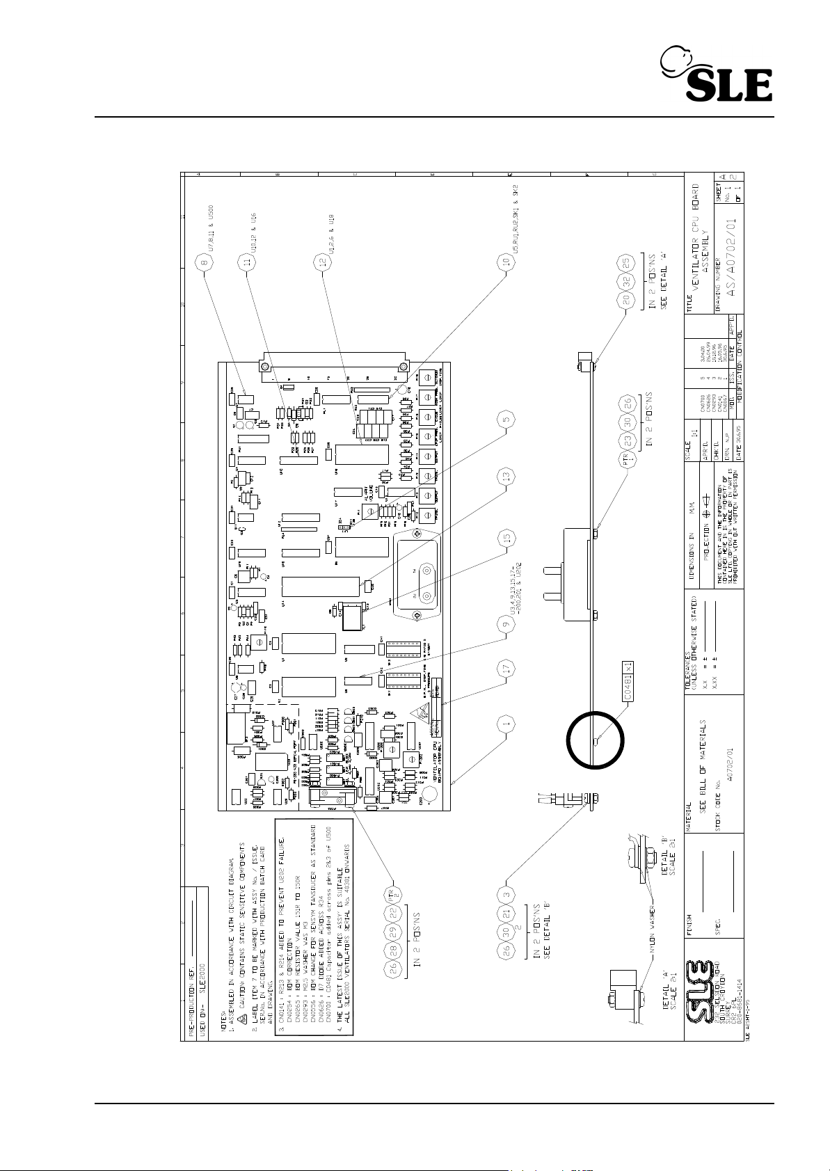
6.5 Ventilator CPU Board AS/A0702/01 Issue 5
See detail A
(SLE2000) Page 89
Page 90
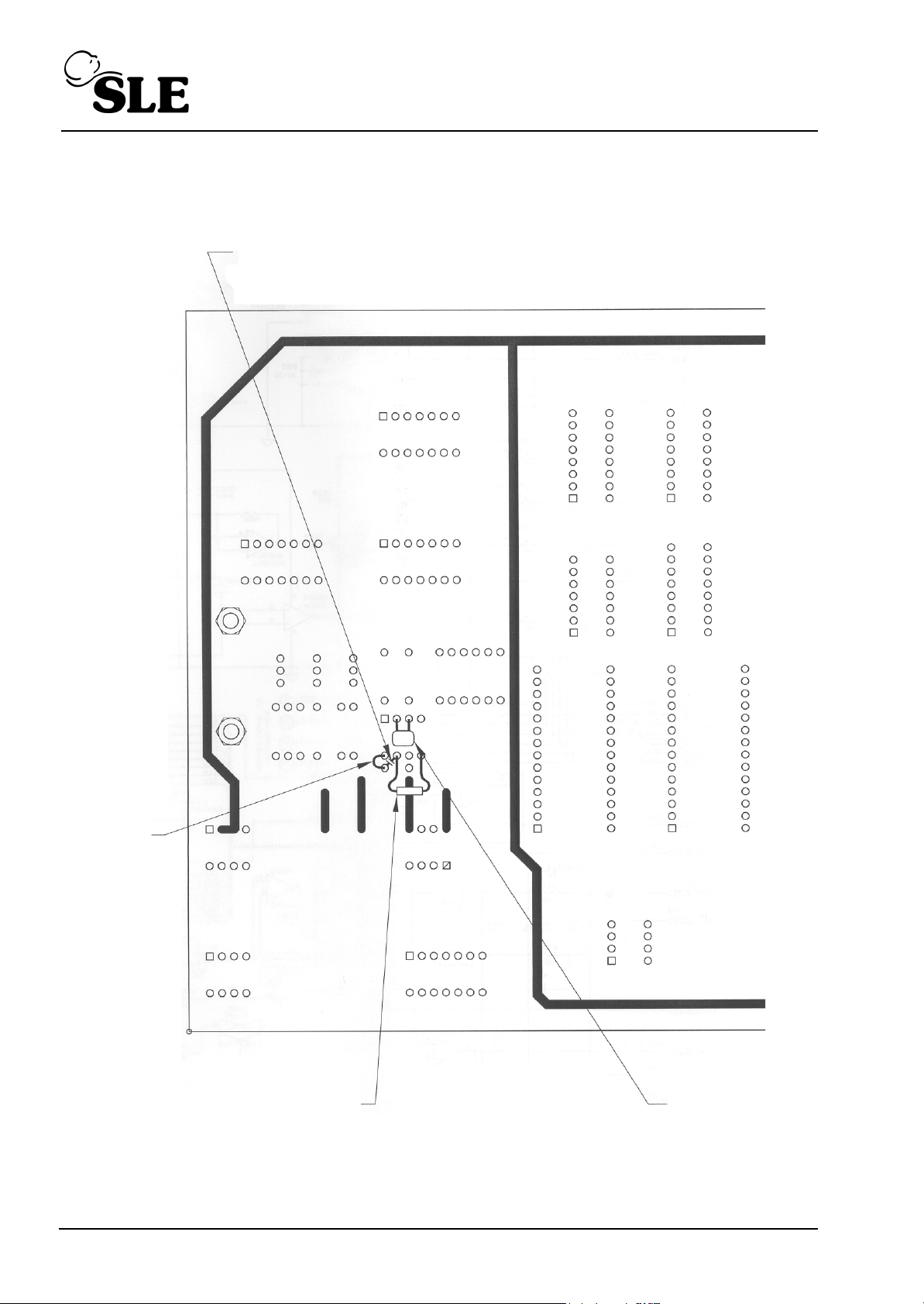
6.5.1 Ventilator CPU Board (Detail A)
C0481
R0658
Link
Cut track
Page 90 (SLE2000)
Page 91
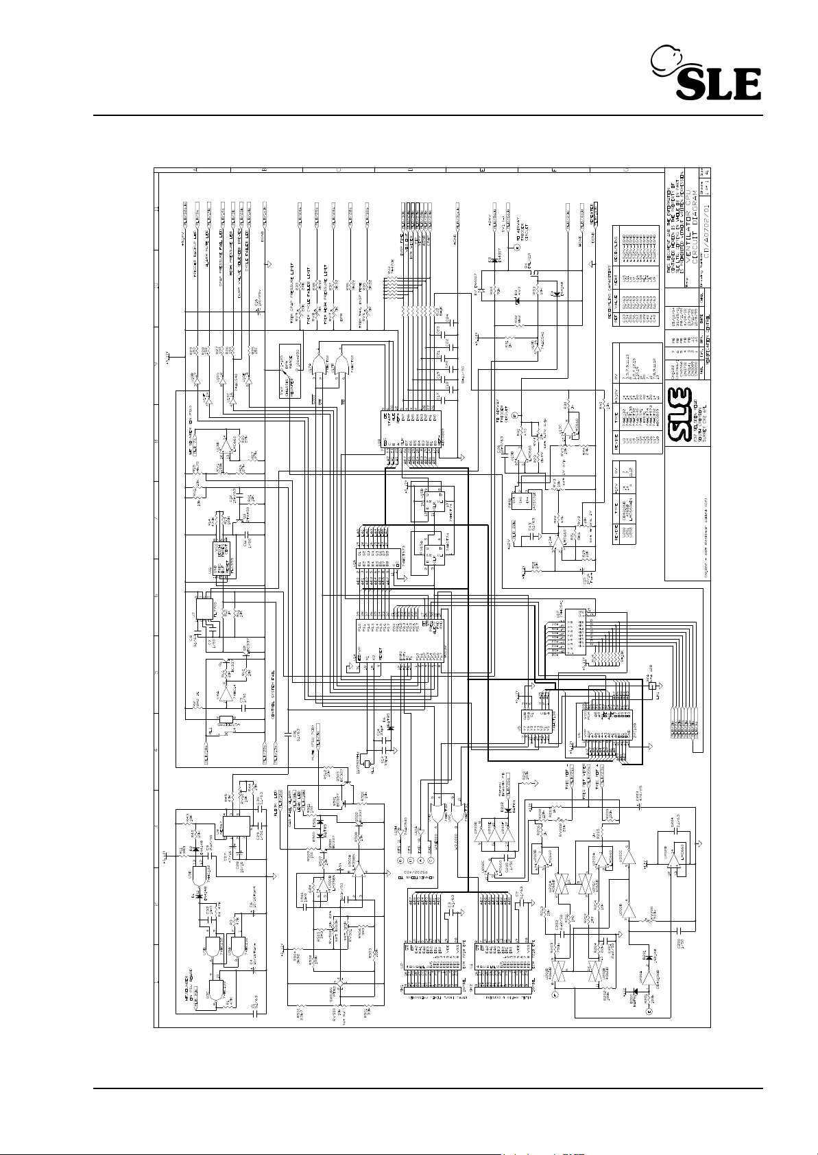
6.5.2 Ventilator CPU Board CD/A0702/01 Issue 7
A3 version on page 149 of circuit diagram appendix.
(SLE2000) Page 91
Page 92
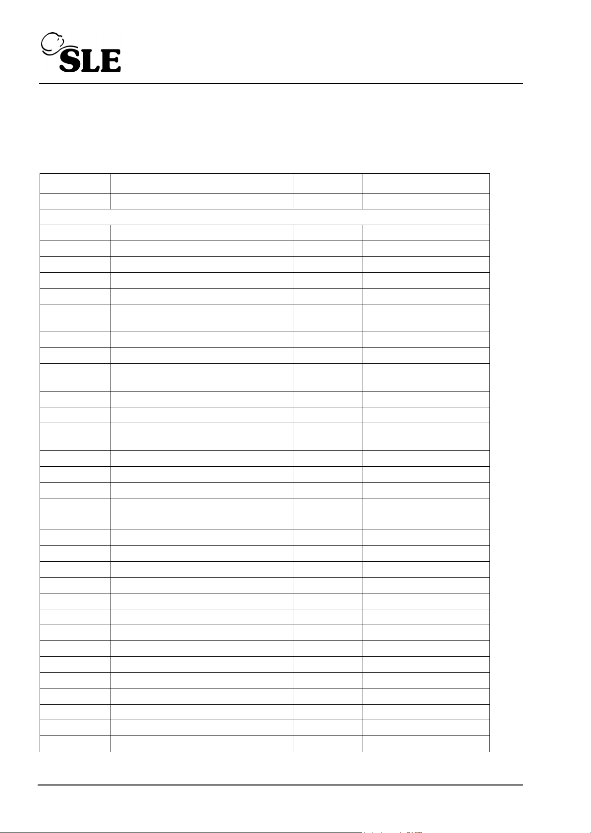
PARTS LIST
Finished Item Stock Number A0702/01
Finished Item Description Ventilator CPU PCB Assembly
Drawing Number AS/A0702/01 Issue 5 but for CD/A0702/01 issue 7
Part Number Component Description Qty Used Component Reference(s)
J0702 Ventilator CPU pcb blank 1.00 Each ITEM 1 (PCB Rev D)
Check pressure transducer type (ITEM PTR2) and read note for component pre-fix.
C0256 47uF Capacitor 16V 10-20% Tan. 1.00 Each C27
C0260 10nF Capacitor 63V 20% MXS2 4.00 Each C12,C26,C32 & C500
C0434 10u Capacitor 35V 20% 5mm Lead 4.00 Each C4,C6,C15 & C28
C0439 100u Capacitor 25V 20% Elect. 1.00 Each C16
C0441 470uF Capacitor 25V 20% 1.00 Each C203
C0450 0.1uF Capacitor 63V 10% MKS2 18.00 Each C1-3,8,30,31,C33-43 &
C204
C0459 2.2uF Capacitor 50V 10% 3.00 Each C9,C201 & & C202
C0461 33pF Capacitor 100V 10% Ceram. 2.00 Each C13 & & C14
C0462 luF Capacitor 50/63V 10% MKS2 14.00 Each C5,7,11,C17-24,C29,C200
& C205
C0481 100nf Capacitor 50v 1.00 Each C2
D0284 BZX79C4V7 (was BZY88C 4v7) 1.00 Each D3
D0288 LM358N 1.00 Each U500=Pt No.D0586 when
pre-fix is not 'S' for PTR2
D0298 ICM7218DlJ1 28 Pin Harris 2 00 Each U1 & U2
D0305 ADC0809CCN NSC 1.00 Each U18
D0320 74HC132N 1.00 Each U3
D0336 BC337 4.00 Each Q1,Q2,Q500 & Q502
D0402 lN4007 Plastic Diode 2.00 Each D5 & D7 (CN0626)
D0406 1N4148 4.00 Each D1,D2,D4 & & D201
D0407 BAT85 4.00 Each D6.D202.D500.D501
D0513 74HC14 1.00 Each U4
D0525 4066 Quad Bilaterial Switch 1.00 Each U201
D0566 TL7705ACP 1.00 Each U7
D0569 BAT81 1.00 Each D200
D0570 Crystal 11.0592 MHz 1.00 Each XL1
D0571 74HCT138N 1.00 Each U5
D0572 74HCT32N 1.00 Each U9
D0573 74HCT74N 1.00 Each U15
D0574 74HCT573N 1.00 Each U16
D0575 74HCT02N 1.00 Each U17
D0576/01 27C128-20/P 1.00 Each U6
D0577 LM567CN 1.00 Each U8
Page 92 (SLE2000)
Page 93

Part Number Component Description Qty Used Component Reference(s)
D0578 74AC540 1.00 Each U10
D0579 74HC541 1.00 Each U12
D0580 TLCSSSCP 1.00 Each U11
D0581 LMC660AIN 2.00 Each U13 & & U202
D0584 CD40106BE 1.00 Each U200
D0585 BC327 2.00 Each Q501 & Q503
D0636 IRLU110 power MOSFET,TO-251 1.00 Each Q4
D0638 ZTX450 1.00 Each Q3
D0644/01 P80C32EBPN 8-bit CMOS CPU 1.00 Each U14
M0626 Jumper Link 1.00 Each ITEM 5
M0660 Pad Adhesive double sided 1.00 Each ITEM 15
M0692 Transistor Pad T05 1.00 Each
M0718 Label, PCB Identification 1.00 Each ITEM 17
N2113 Pressure Transducer 142SCOlD 1.00 Each PTR1
N2176 Sensor SXOlDN (Sensym only) 1.00 Each PTR2
If N2176 is not Pre-Fixed with M on component then R501 becomes 33K(PT No.R0473) & U500
becomes LM358(PT No.D0288)
00227 Relay W172DIP-5 5V DC 1.00 Each RL1
P0230 DIN41612 64 Way 90 deg Plug 1.00 Each PLB
P0464 12way P.C.B Header Straight 0.25 Each LKl (3 PIN SECTION)
R0224 30K Resistor 0.25W 18 0 00 Each replaced by R0549
CN0626
R0226 110K Resistor 1% 0.25W 1.00 Each R208
R0349 24K Resistor 0.25W 1% 2.00 Each R24 & & R39
R0350 1K x 8 Resistor Network 1.00 Each RU2
R0351 10K x 8 Resistor Network 1.00 Each RU1
R0416 150R Resistor 1% 0.25W SMA0207 7.00 Each R25-R29,R509 & R511
R0428 470R Resistor 1% 0.25W 1.00 Each R41
R0436 1.0K Resistor 1% 0.25W SMA0207 6.00 Each R12,R30,R31,R205-R207
R0445 2K49 Resistor 1% 0.25W SMA0207 1.00 Each R23
R0446 2.7K Resistor 1% 0.25W 0.00 Each replaced by R0461CN0626
R0449 3.32K Resistor 1% 0.25W SMA 2.00 Each R35 & & R37
R0451 3.92K Resistor 1% 0.25W SMA020 2.00 Each R38 & & R504
R0454 4.75K Resistor 1% 0.25W 1.00 Each R15
R0456 5.6K Resistor 1% 0.25W SMA0207 1.00 Each R21
R0461 8.2K Resistor 1% 0.25W 1.00 Each R32
R0462 9.09K Resistor 1% 0.25W SMA020 1.00 Each R36
R0463 10K Resistor 1% 0.25W SMA0207 10.00 Each R18,19,33,40,42,43,507,50
8,510 & R512
R0467 15K Resistor 1% 0.25W SMA0207 1.00 Each R44
(SLE2000) Page 93
Page 94

Part Number Component Description Qty Used Component Reference(s)
R0469 22.1K Resistor 1% 0.25W SMA020 1.00 Each R204
R0470 23.7K Resistor 1% 0.25W 1.00 Each R500
R0471 27K Resistor 1k 0.25W SMA0207 3.00 Each R16,R17 & R20
R0473 33K Resistor 1% 0.25W 1.00 Each R501=Pt No.R0467when
pre-fix is not 'S' for PTR2
R0479 47K Resistor 1% 0.25W SMA0207 5.00 Each R1,R3,R4,R22 & R45
R0486 100K Resistor 1% 0.25W SMA0207 7.00 Each R13,R201,202,209
,210,502,R503
R0496 470K Resistor 1% 0.25W SMA0207 1.00 Each R14
R0499 750K Resistor 1% 0.25W 1.00 Each R203
R0501 1.0M Resistor 1% 0.25W SMA0207 2.00 Each R211 & R212
R0504 2.2M Resistor 16 0.25W 1.00 Each R2
R0506 3.3M Resistor 1% 0.25W SMA0207 3.00 Each Rll,R505 & R506
R0549 91K Resistor 1% 0.25w 1.00 Each R34
R0555 470K x 8 Resistor Network 1.00 Each RU3
R0556 10K x 8 Resistor Network 1.00 Each RU4
R0571 10k Resistor 1% 0.125W M/Film 2.00 Each R213 & R214
R0658 68M Resistor 0.25W High Ohmic 1.00 Each
S0209 IC Socket 28 way DIL 4.00 Each ITEM 12
S0212 IC Socket 16 way DIL 5.00 Each ITEM 10 (U5,RU1,2 ,SKl &
SK2)
S0227 IC Socket 40 way DIL 1.00 Each ITEM 13
S0237 IC Socket 20 way DIL 3.00 Each ITEM 11
S0241 IC Socket 8 way DIL 4.00 Each ITEM 8 (U7,8,11&U500 )
S0242 IC Socket 14 way DIL 9.00 Each ITEM 9
T0205 Alarm Transducer Bracket 1.00 Each ITEM 3
V0404 5.0K Trimmer,cermet,top adjust 3.00 Each RV6-RV8
V0405 10K Trimmer, cermet, top adj 5.00 Each RV2-RV5 & RV10
V0406 20K Trimmer cermet,top adjust 2.00 Each RV9,RV202
V0408 100K Trimmer, cermet, top adj 1.00 Each RV1
V0410 500K Trimmer 1.00 Each RV200
V0414 10K Trimmer, cermet, top adj 3.00 Each RV500-RV502
H3116 M3 x 16 Pan Hd Pozi s.st 2.00 Each ITEM 22
H3108 M3 x 8 Pan Hd Pozi s.st 2.00 Each ITEM 21
H3225 M3 x 25 Csk Hd Pozi s.st 2.00 Each ITEM 23
H2312 M2.5 x 12 Pan Hd Pozi s.st 2.00 Each ITEM 20
H3091 M3 Nut Full s.st 6.00 Each ITEM 26
H2591 M2.5 Nut Full s.st 2.00 Each ITEM 25
H2595 M2.5 Plain Nylon Washer 2.00 Each ITEM 32
H3094 M3 S/Proof Washer s.st DIN6798 6.00 Each ITEM 28
H3095 M3 Plain Washer Nylon 6.00 Each ITEM 30
Page 94 (SLE2000)
Page 95

Part Number Component Description Qty Used Component Reference(s)
H3093 M3 Plain Washer B . st 2.00 Each ITEM 29
W0112 Tinned copper wire 22swg 0.01 Metre See detail A
(SLE2000) Page 95
Page 96
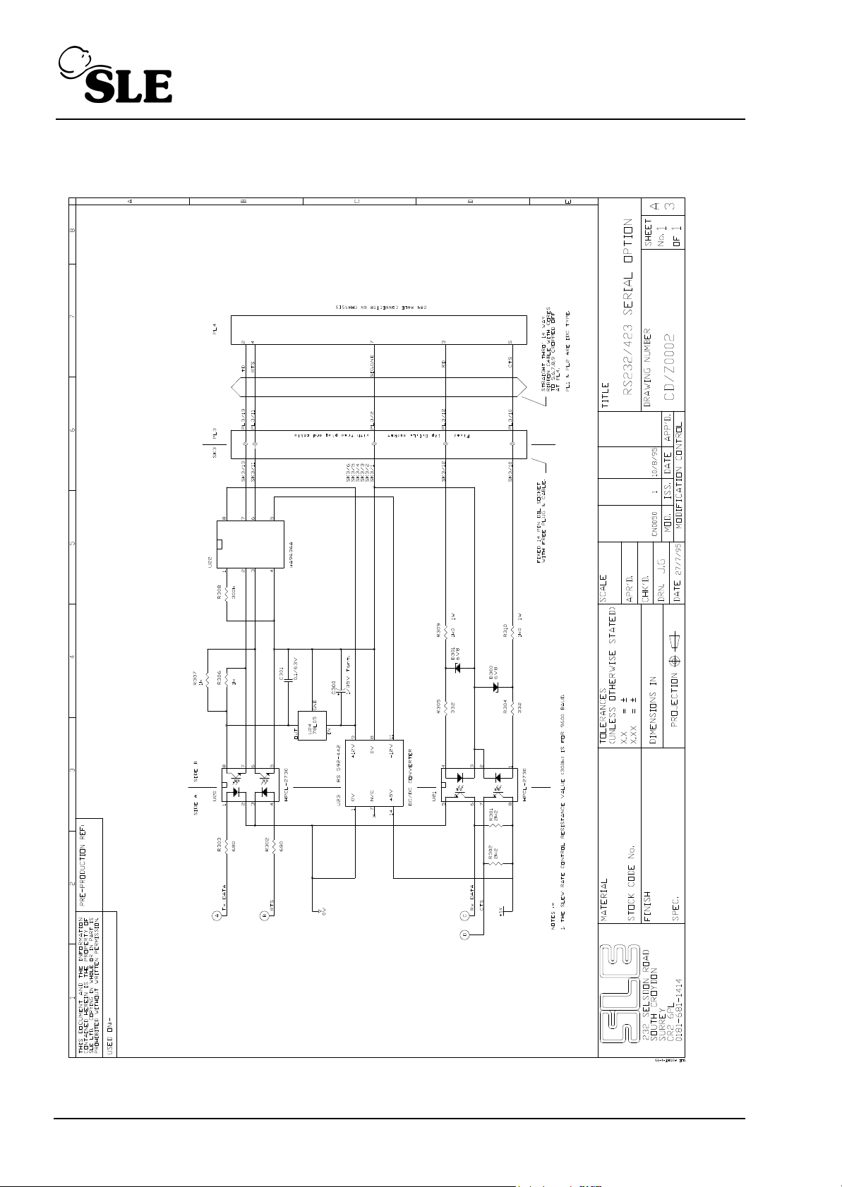
6.6 RS232/423 Option
Page 96 (SLE2000)
Page 97

PARTS LIST
Finished Item Stock Number A0702/03
Finished Item Description RS232/423 option.(A0702 PCB)
Part Number Component Description Qty Used Component Reference(s)
D0643 HPCL 2730 2 U20,21
D0640 UA9636ACP 1 U22
D0593 NMA0512D 1 U23
D0432 LM7805CT Regulator 1 U24
D0250 BZX79C6V8 2 D300,301
R0443 2.2K Resistor 1% 0.25W SMA0207 2
R0432 680R Resistor 1% 0.25W 2 R302,303
R0425 332R Resistor 1% 0.25W SMA0207 2 R304,305
R0436 1.0K Resistor 1% 0.25W SMA0207 2 R306,307
R0343 300K 1% 50PPM 0.25W 1 R308
R0557 1K0 Resistor 5% 1W 250PPM PR01 2 R309,310
C0433 1uF Capacitor 35V 20% Tantalum 1
C0450 0.1uF Capacitor 63V 10% MKS2 1 C301
S0241 IC Socket 8 way DIL 3 U20,21,22
S0242 IC Socket 14 way DIL 1 SK3
R300,301
C300
(SLE2000) Page 97
Page 98

P.S.U. PCB assembly
AS/A0703/01 Issue 3 PSU PCB assembly (See AS/A0703/01 issue 3 on page 99).
Alarm sounder backup modification
AS/A0703/01 Issue 7 Addition of D0407 Diode to allow BZ3 sounder to act as a backup
sounder to BZ2 (See AS/A0703/01 issue 7 on page 103).
CD/A0703/01 Issue 5 Addition of D0407 between PLB/21b and PLB/8b.
Also see service information “SI 050701 Activation of watchdog secondary alarm sounder in
case of primary alarm sounder failure.” on page 167.
Addition of A0703/03 sounder backup board
AS/A0703/01 Issue 8 Removal of D0407 Diode and N2096 sounders (See AS/A0703/
01 Issue 8 on page 107).
CD/A0703/01 Issue 6 Removal of D0407 Diode and N2096 sounders.
Also see service information “SI 070301 Design and component change to the A0703/01
PSU PCB” on page 173.
Page 98 (SLE2000)
Page 99
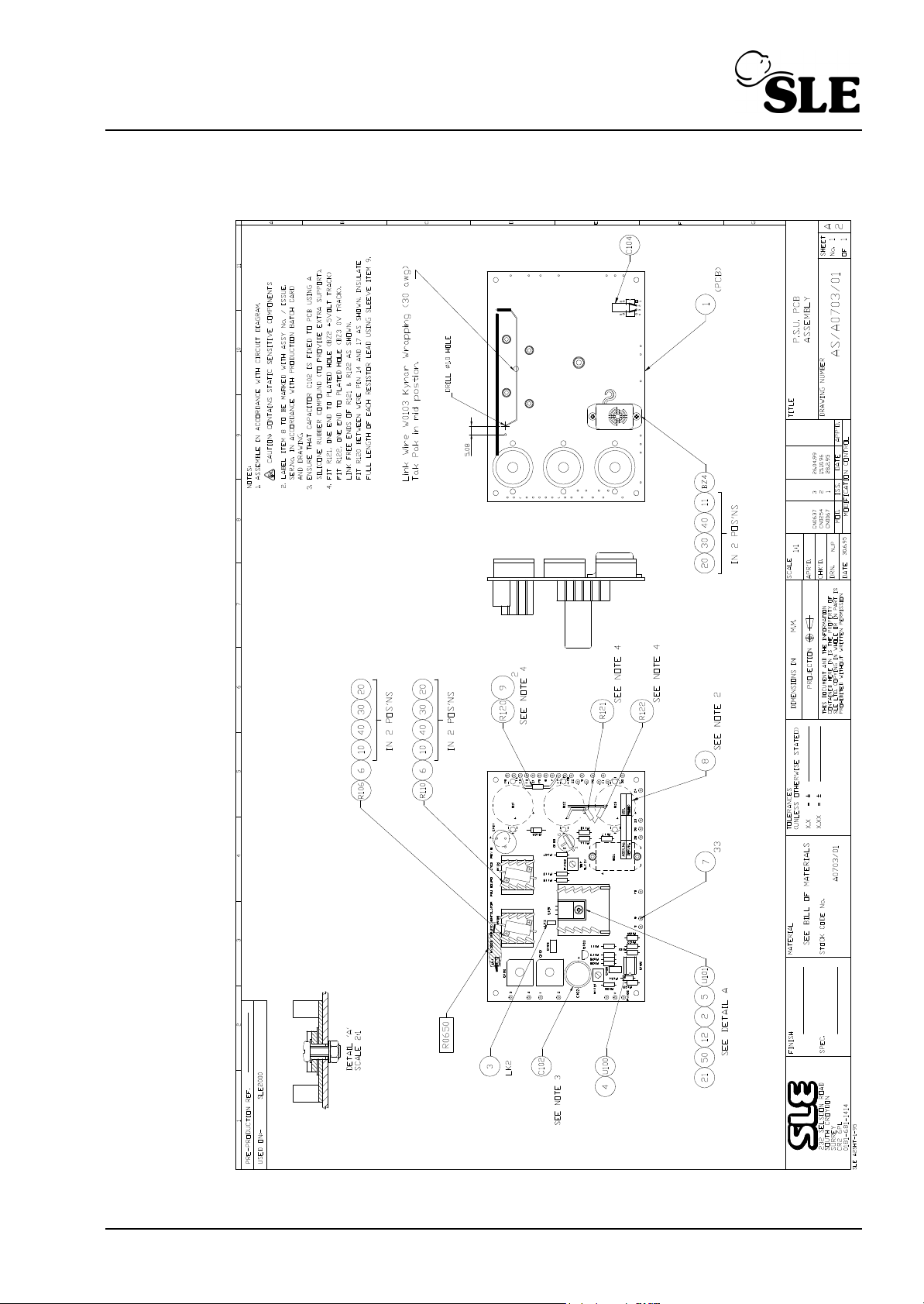
6.7 PSU PCB AS/A0703/01 issue 3
(SLE2000) Page 99
Page 100
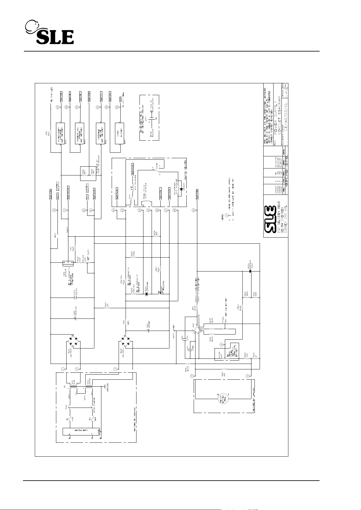
6.7.1 Power Supply Circuit Diagram CD/A0703/01 issue 4
Page 100 (SLE2000)
 Loading...