

Page 1
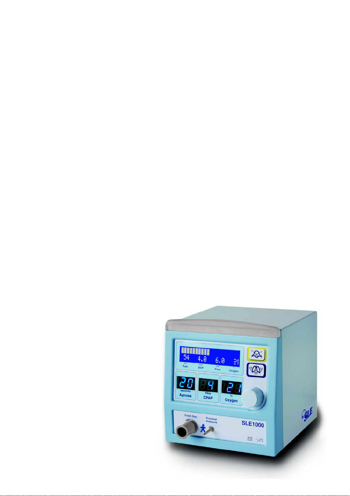
SLE1000
User manual
Version 2.6.4 software
Page 2

Contact Information:
SLE Limited
Twin Bridges Business Park
232 Selsdon Road
South Croydon
Surrey CR2 6PL
Telephone: +44 (0)20 8681 1414
Fax: +44 (0)20 8649 8570
E-mail: Sales/Training enquires: [email protected]
Web site: www.sle.co.uk
Technical enquires: [email protected]
All rights reserved. No part of this publication may be reproduced, stored in any retrieval system, or transmitted
in any form or by any means, electronic, mechanical, photocopy, recording or otherwise, without prior
permission of SLE. © Copyright SLE 10/08/2016.
Manual : UM114 Issue 21
SLE Part Nº: L1009/UMA/0UK
Page 2 of 128
Page 3

This manual is for SLE1000 CPAP Therapy
System
How To Use The
SLE1000 CPAP Therapy System
The warnings on pages 19 to 22 must be read and understood
before using the SLE1000 CPAP Therapy System. Failure to do
so could lead to injury of the patient.
1 SETUP THE SLE1000: Page 70
2 MAKE SURE THAT THE SLE1000’s BACK-UP POWER
SUPPLY IS FULLY CHARGED: Page 77.
3 THE SLE1000 IS READY FOR PATIENT CONNECTION AND
USE. Page: 88
For more information see “Technical Section”, page 106.
For trouble shooting see “Troubleshooting Chart”, page 90.
Page 3 of 128
Page 4

This page is intentionally blank.
Page 4 of 128
Page 5

Contents
1. Introduction .............................................................................................................10
1.1. Device ............................................................................................................10
1.2. Accessories and generic combination devices...............................................11
1.3. Intended use...................................................................................................11
1.4. Intended users................................................................................................11
2. SLE1000 Description ..............................................................................................14
3. Description of symbols ..........................................................................................16
4. User/owner responsibility ......................................................................................18
5. Warnings ..................................................................................................................19
5.1. Operational warnings .....................................................................................19
5.2. Clinical warnings.............................................................................................22
6. User interface ..........................................................................................................24
6.1. Main LCD display ...........................................................................................24
6.2. LED display windows......................................................................................24
6.3. Push and turn knob ........................................................................................25
6.4. Audio paused and boost buttons....................................................................25
6.5. Light bar .........................................................................................................25
7. Operation .................................................................................................................26
7.1. Power up ........................................................................................................26
7.2. Oxygen calibration routine description ...........................................................29
7.3. Power down....................................................................................................30
8. Standby mode .........................................................................................................31
8.1. Exiting Standby mode ....................................................................................31
9. Selecting a parameter, display or calibration function .......................................32
9.1. Upper and lower level functions. ....................................................................32
9.2. Upper level functions, displays and parameters.............................................37
9.3. Showing battery charge level .........................................................................39
9.4. Alarm history ..................................................................................................42
9.5. Set Flow .........................................................................................................44
9.6. Elapsed time counter......................................................................................46
10. Audio mute button ................................................................................................47
10.1. Pre-mute.......................................................................................................47
10.2. Audio paused ...............................................................................................48
11. Boost button ..........................................................................................................50
12. Indicators ...............................................................................................................51
12.1. Cycle indicator bargraph...............................................................................51
12.2. Breath detection ...........................................................................................51
12.3. Averaged value ............................................................................................52
12.4. Measured values..........................................................................................52
12.5. Battery and mains indicators........................................................................53
Page 5 of 128
Page 6

12.6. Power related faults......................................................................................53
13. CPAP & Flow mode ...............................................................................................56
13.1. Standby to Flow mode..................................................................................56
13.2. Setting a flow in flow mode...........................................................................58
13.3. Flow mode to CPAP mode............................................................................61
13.4. Standby to CPAP mode................................................................................63
13.5. CPAP to Flow mode......................................................................................65
14. SLE1000 Set-up .....................................................................................................70
14.1. First use........................................................................................................70
14.2. Rotation of gas inlets ....................................................................................72
14.3. Water trap and particulate filter.....................................................................72
14.4. Standard setup..............................................................................................73
14.5. Disconnection of air and oxygen hoses........................................................76
14.6. Battery charging............................................................................................77
14.7. Battery care...................................................................................................77
14.8. Using the SLE1000 on battery power...........................................................77
14.9. Mains isolation..............................................................................................78
14.10. Extended storage and transportation..........................................................78
15. Functional testing prior to patient use ...............................................................80
15.1. Battery test....................................................................................................81
15.2. Mains disconnect alarm................................................................................81
15.3. Total power fail alarm test.............................................................................82
15.4. High leak and high pressure alarm ...............................................................82
15.5. Apnoea alarm................................................................................................82
15.6. Zero pressure alarm and purge check..........................................................83
15.7. Gas supply alarms........................................................................................83
16. Operational considerations ..................................................................................86
16.1. General.........................................................................................................86
16.2. CPAP............................................................................................................86
17. Basic operation .....................................................................................................88
17.1. Monitoring.....................................................................................................88
17.2. Operation......................................................................................................88
18. Troubleshooting chart ..........................................................................................90
Technical Information 93
19. Cleaning and disinfection .....................................................................................94
19.1. Preparation of a new SLE1000 CPAP driver................................................94
19.2. Cleaning and disinfection of an in-service driver ..........................................94
19.3. Cleaning Method...........................................................................................95
19.4. Disinfection method ......................................................................................95
20. Messages & alarms ...............................................................................................96
20.1. Messages......................................................................................................96
20.2. Alarm messages and sounds........................................................................98
Page 6 of 128
Page 7

21. Technical specification ........................................................................................106
21.1. Operating mode............................................................................................106
21.2. Monitoring.....................................................................................................106
21.3. Indicators......................................................................................................106
21.4. Controls........................................................................................................106
21.5. Alarms ..........................................................................................................107
21.6. Outputs.........................................................................................................107
21.7. Oxygen sensor life........................................................................................107
21.8. Gas supplies.................................................................................................108
21.9. Operating environment.................................................................................108
21.10. Power requirements ...................................................................................109
21.11. Dimensions.................................................................................................109
21.12. Classification ..............................................................................................109
21.13. Environmental storage conditions ..............................................................109
21.14. Product life cycle ........................................................................................109
22. Maintenance schedule ..........................................................................................110
22.1. SLE1000 service requirements ....................................................................110
22.2. Maintenance schedule .................................................................................110
22.3. Preventative Maintenance............................................................................111
23. EMC compliance ...................................................................................................112
23.1. Electromagnetic immunity ............................................................................113
23.2. Recommended separation distances between portable and mobile RF
communications equipment and the SLE1000......................................................115
24. RS232 .....................................................................................................................116
24.1. RS232 output specification:..........................................................................116
25. Pneumatic unit schematic SLE1000 ....................................................................117
26. SLE1000 Overlay ...................................................................................................118
27. Equipment checklist .............................................................................................119
28. Consumables and accessories ...........................................................................122
29. Glossary of abbreviations used in this manual .................................................124
30. Index .......................................................................................................................125
Page 7 of 128
Page 8

This page is intentionally blank.
Page 8 of 128
Page 9

Introduction
Page 9 of 128
Page 10
1. Introduction
1.1 Device
The SLE1000 is a CPAP driver for delivering an air-oxygen treatment gas to patients via
nasal prongs or nasal mask. The SLE1000 is intended for providing CP AP to treat infant and
neonatal patients with compromised respiratory systems while in an acute or sub-acute
hospital environment.
The SLE1000 can be operated from either wall serviced, compressor or bottled pressurized
air and oxygen sources in the range 2 to 7 bar.
The SLE1000 has been designed so that it can be used with only a compressed air supply.
The SLE1000 automatically corrects the flow rate, to maintain the set CPAP or maintains the
set flow.
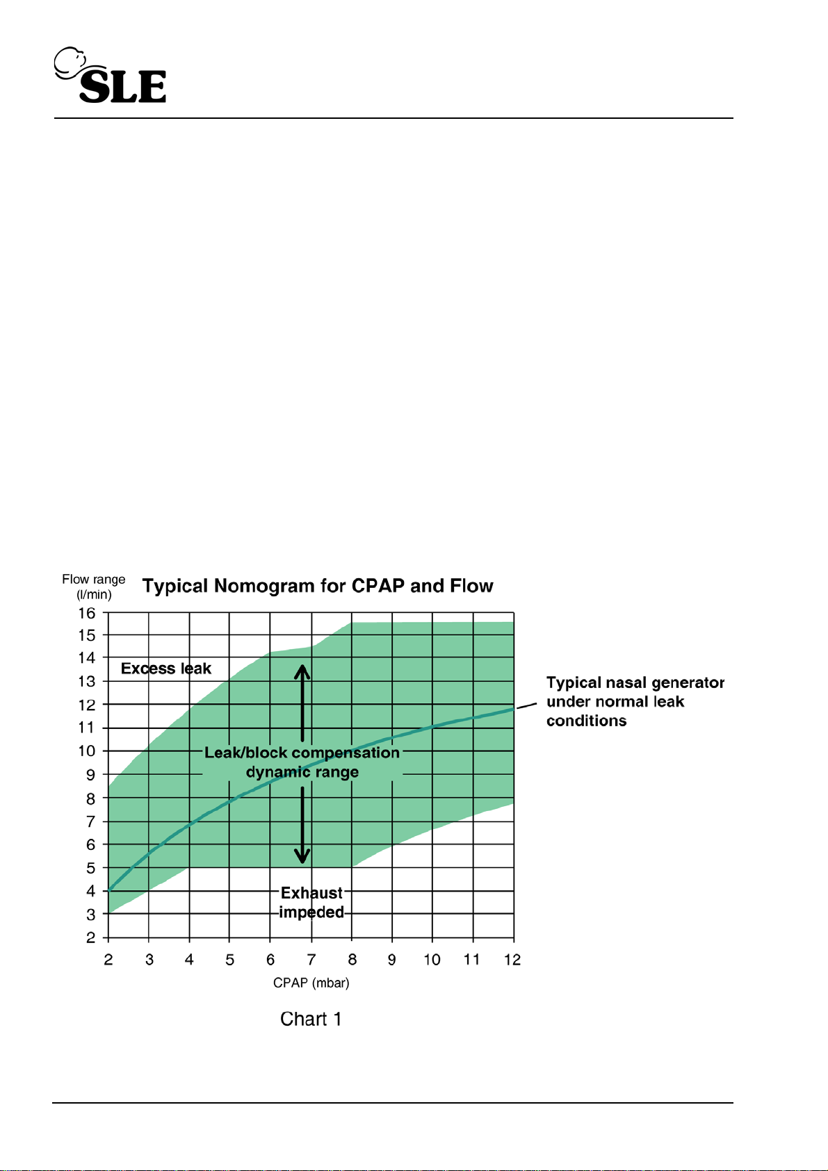
‘Typical’ flow-CPAP relationship is shown by the centre line in the nomogram below. This is
the relationship produced by common Nasal Generators.. The line also represents the
SLE1000 default calibration settings.
The highlighted area in the nomogram below represents the whole operating range. The
SLE1000 will alarm if the patient leak or the exhaust impedance (block) is excessive and
causes the automated flow correcting to reach a boundary of the operating zone.
Page 10 of 128
Page 11

1.2 Accessories and generic combination devices
The SLE1000 can be used to drive CPAP through a generic humidified and heated patient
circuit, with or without a bacteria filter, to any universal patient interface, including nasal
prongs, flow generator, or nasal mask that operate within tolerance of chart 1.
1.3 Intended use
The SLE1000 is intended to provide pressure support up to 12 mbar, to neonates and
infants. The device is intended for use in the hospital environment where care is provided by
medical professionals and includes use at bedside and for intra hospital transport provided
compressed gas is available.
1.4 Intended users
The SLE1000 is to be used by appropriately trained and authorized personnel only. In this
manual they will be referred to as the “User”.
Page 11 of 128
Page 12

This page is intentionally blank.
Page 12 of 128
Page 13

SLE1000 Description
Page 13 of 128
Page 14
2. SLE1000 Description
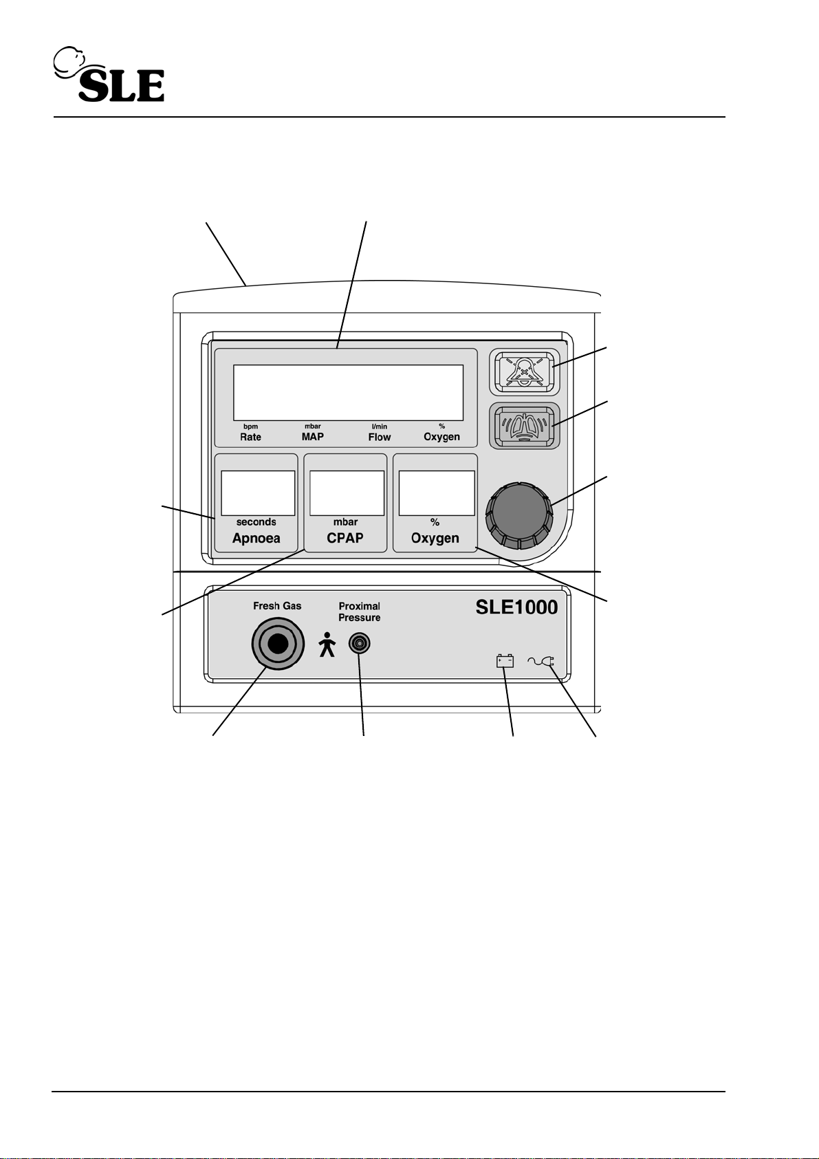
Light bar
Main LCD display
Battery icon Mains disconnect
Fresh gas port
% Oxygen
Proximal airway port
CPAP Boost
button
Alarm mute
button
Main control
knob
icon
display
Set pressure
display
Set apnoea
time display
Front View
Page 14 of 128
Page 15
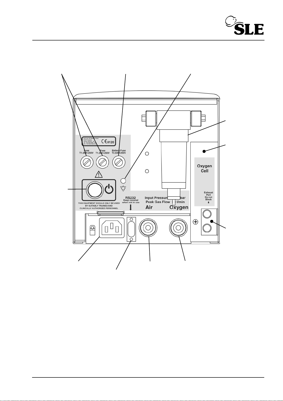
Mains power inlet
RS232
Water trap
Air supply
inlet
Oxygen supply
inlet
Mains Fuse Holder
Exhaust port
Connector
Battery
Fuse Holder
Mains power
switch
Equipotential stud
Oxygen cell
cover
Rear View
Page 15 of 128
Page 16
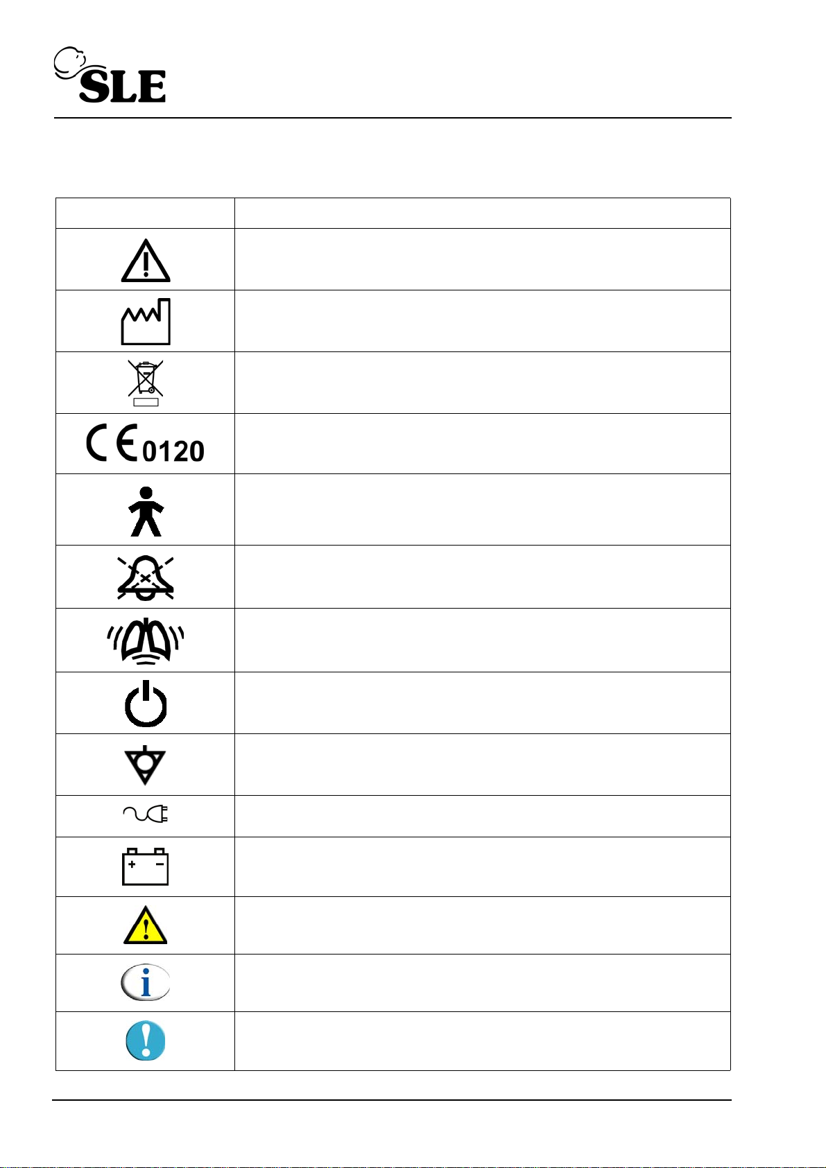
3. Description of symbols
Symbol Description
Read manual (Situated on rear panel).
Date of Manufacture (Appears on serial number label).
Do not dispose of as general waste (WEEE directive).
(Appears on serial number label).
EEC conformity marking showing compliance with the Medical
Devices Directive.
Symbol for degree of protection against electric shock. Type B
applied part. (Appears on front panel)
Alarm mute.
CPAP boost.
Indicates the mains power switch.
Equipotential point.
Mains power not present, (when illuminated).
Battery icon
Indicates a warning in the manual.
Indicates a note in the manual.
Page 16 of 128
Indicates a caution in the manual.
Page 17

Operational and Clinical Warnings
Page 17 of 128
Page 18

4. User/owner responsibility
The SLE1000 and the authorised accessories for it are designed to be used in accordance
with supplied manuals and instructions. This equipment must be periodically checked,
recalibrated, maintained (as per maintenance schedule) and components repaired and
replaced when necessary for the equipment to operate safely and reliably.
Parts that have failed, in whole or in part, or exhibit excessive wear, or are contaminated, or
are otherwise at the end of their useful life, should not be used and must be replaced
immediately with parts supplied by SLE, or parts which are otherwise approved by SLE.
Equipment which is not functioning correctly or is otherwise in need of repair or maintenance
must not be used until all necessary repairs and/or maintenance have been completed and a
factory authorised service representative has certified that the equipment is fit and ready for
use. This equipment, its accessories or component parts should not be modified. The use of
non-approved parts or accessories will invalidate the warranty.
The owner/user of this equipment shall have the sole responsibility and liability for any
damage or injury to persons or property (including the equipment itself) resulting from
operation not in accordance with the operating instructions, or from faulty maintenance not
in accordance with the authorised maintenance instructions, or from repair by anyone other
than the factory authorised service representative, or from unauthorised modification of the
equipment or accessories, or from the use of components or accessories that have been
either damaged or not authorised for use with this equipment by the manufacturer.
Page 18 of 128
Page 19

5. Warnings
5.1 Operational warnings
The following warnings must be read and understood before using the SLE1000. Failure to
do so could lead to injury or death of the patient.
5.1.1 General
1. The whole of this manual should be read and understood before using the SLE1000.
Operators must be suitably trained and clinically authorised for using the SLE1000 with
patients.
2. Oxygen - Clinical use. Oxygen is a drug and should be prescribed as such.
3. Oxygen - Fire Hazard. Oxygen vigorously supports combustion and its use requires
special precaution to avoid fire hazards. Keep all sources of ignition away when oxygen
is in use. Do not use oil or grease on oxygen fittings or where oxygen is used.
4. The SLE1000 is not a dedicated transport device and does not conform to the
requirements of BS EN 794-3.
5. Always disconnect the air and oxygen hoses from the wall outlets prior to disconnection
from the unit.
6. Do not use in the presence of flammable anaesthetics.
7. Check the condition of the gas supply hoses to the SLE1000. Do not use any hose that
shows signs of cracking, abrasion, kinking, splits, excessive wear or ageing. Make sure
that the Air or O2 hose has not come into contact with oil or grease.
8. Audible and Visual warning alarms indicate a potentially harmful condition to the patient.
9. The patient must not be connected to the unit in “Standby” mode. The unit does not
deliver any therapeutic flow in this modes. In “St andby” mode all p atient and gas alarms
are disabled with the exception of the “Low battery” alarm and all system failure alarms.
10. When the SLE1000 is being used on a patient, a suitably trained person must be in
attendance at all times to take prompt action should an alarm or other indication of a
problem occur.
11. The SLE1000 must not be used as the sole form of patient monitoring. Independent
monitoring of blood gases should be used in conjunction with the SLE1000. Breath
detection technology used in the apnoea monitor function is based on rate and
magnitude of change in the pressure measured in the patient interface (that is shown on
the bar graph). The sensitivity of the technology has limitations with the smallest patients
(<1000g) and if a leak exists or if the patient opens/breathes by the mouth. The apnoea
monitor may be disabled if breath non-detection / over detection results in nuisance
Apnoea / High BPM alarms.
12. At low CP AP pressures (<4mbar) it is possible for the unit not to detect a leak condition,
even in the presence of large leak.
Page 19 of 128
Page 20

13. An alternative form of ventilation should be available whenever the SLE1000 is in use,
in the event of failure.
14. Do not touch the patient and SLE1000 metalwork at the same time to avoid earthing the
patient.
15. The SLE1000 is not compatible with MRI equipment or other equipment radiating high
EM fields.
16. The SLE1000 contains temperature dependant devices which perform normally in
controlled environments in hospitals. However if the SLE1000 has been stored at a
temperature different to that in which it will be used, allow the unit to acclimatize before
powering up, if difference greater than 10°C allow 2 hours. (See “Environmental storage
conditions” on page 109).
17. Any computer connected to the SLE1000 must be specified for medical use.
18. The SLE1000 does not use Latex, nor was it used in its construction.
19. The SLE1000 is not protected against the ingress of water. (IP20)
20. Do not cover the SLE1000 or allow the SLE1000 to become covered by any fabric or
curtain. Do not allow the exhaust ports or inlet vents to become obstructed or blocked by
positioning the SLE1000 near curtains or fabric.
21. The SLE1000 does not support automatic record keeping.
22. The SLE1000 has no emergency air intake.
23. The SLE1000 functional test routine must be carried out each time the SLE1000 is used
on a patient. If any of these tests do not function as described then there is a problem
and the SLE1000 must not be used until it is rectified.
24. Failure to comply with the recommended service programs could lead to injury of the
patient, operator or damage to the SLE1000. It is the owners responsibility to ensure
that the equipment is regularly maintained.
25. The SLE1000 must be connected to a suitably rated and grounded electrical power
source.
26. The SLE1000 must not be started on battery power alone.
27. The SLE1000 must have its batteries charged at least every 10 days. The SLE1000
must be connected to a mains power source for 8 hours to ensure a full charge. Failure
to charge the batteries will shorten the service life of the batteries which will result in
reduced battery life in a mains power fail situation.
28. The SLE1000 can operate on battery power in the event of mains power failure for a
maximum of 4 hours (If battery fully charged at start of mains power failure). Whilst on
battery power an alternative form of ventilation should be made ready if the mains
power supply cannot be restored.
Page 20 of 128
Page 21

29. If the SLE1000 is operating on battery power and allowed to completely discharge the
battery, it should be recharged a soon as possible. This is to avoid damaging the
batteries by allowing them to remain in a deep discharged state for any period of time.
Allowing the batteries to remain in the deep discharged state will shorten the life of the
batteries and the amount of time the SLE1000 can remain on battery power.
30. If the SLE1000 is not to be used for a period in excess of 10 days then disconnect the
batteries from the power supply. (See “Extended storage and transportation” on
page 78).
31. If the SLE1000 is adversely affected by equipment emitting electromagnetic interference
then that equipment should be switched off or removed from the vicinity of the SLE1000.
Conversely, if the SLE1000 is the source of interference to other neighbouring
equipment, it should be switched off or taken to another location.
32. The functioning of this machine may be adversely affected by the operation of
equipment such as high frequency surgical (diathermy) equipment, defibrillators, mobile
phones or short-wave therapy equipment in the vicinity.
33. Do not clean the SLE1000 whilst the unit is in operation.
34. Disposal of the Oxygen cell should be in accordance with local regulations for
hazardous substances. Do not incinerate. SLE offers a cell disposal service.
35. The SLE1000 contains one sealed lead acid battery. At the end of its useful life this
battery should be disposed of in accordance with local authority guidelines. Note: the
battery should only be replaced by service personnel.
36. Apart from the battery and O2 cell, the SLE1000 and accessories do not contain any
hazardous components therefore no special precautions are required for their disposal.
The SLE1000 should be disposed of in accordance to the local WEEE (Waste Electrical
and Electronic Equipment) guidelines.
37. Care should be taken when attaching other equipment as this may affect mechanical
stability.
38. In the event of main LCD screen failure remove the patient as soon as possible (under
clinical supervision) from the SLE1000 to an alternative form of ventilation. The
SLE1000 will continue to deliver CPAP on the set parameters whilst this is arranged.
39. Do not use solvent based cleaning solutions to clean the SLE1000.
5.1.2 Humidifier / Patient Circuit
40. The patient circuit tubing should conform to EN12342 (ISO5367:2000) (non kink
requirements).
41. On no account should antistatic or electrically conductive tubing be used.
42. The humidifier used in the patient circuit must be operated and maintained in
accordance with its manufacturer’s instructions.
5.1.3 Compressor
43. When using a compressor the user must use the correct start-up routine otherwise the
watertrap will bleed air. (See section 14.4.3 on page 75).
Page 21 of 128
Page 22

5.2 Clinical warnings
Failure to take corrective action when the alarms are activated could result in injury to the
patient.
There are risks inherent in the use of ventilatory support in the neonatal and infant patient.
These may include:
1. Damage to nares.
2. Under- or over- ventilatory support (with consequent abnormalities in blood gases);
3. Incorrect humidification; could cause mobilisation of secretions and airway blockage.
4. Damage to trachea and bronchi;
5. Over- or under- inflation of the lung;
6. Atalectasis;
7. Air leak syndrome (pneumothorax, pneumomediastinum, pneumopericardium.
pulmonary interstitial emphysema).
Page 22 of 128
Page 23

User interface
Page 23 of 128
Page 24
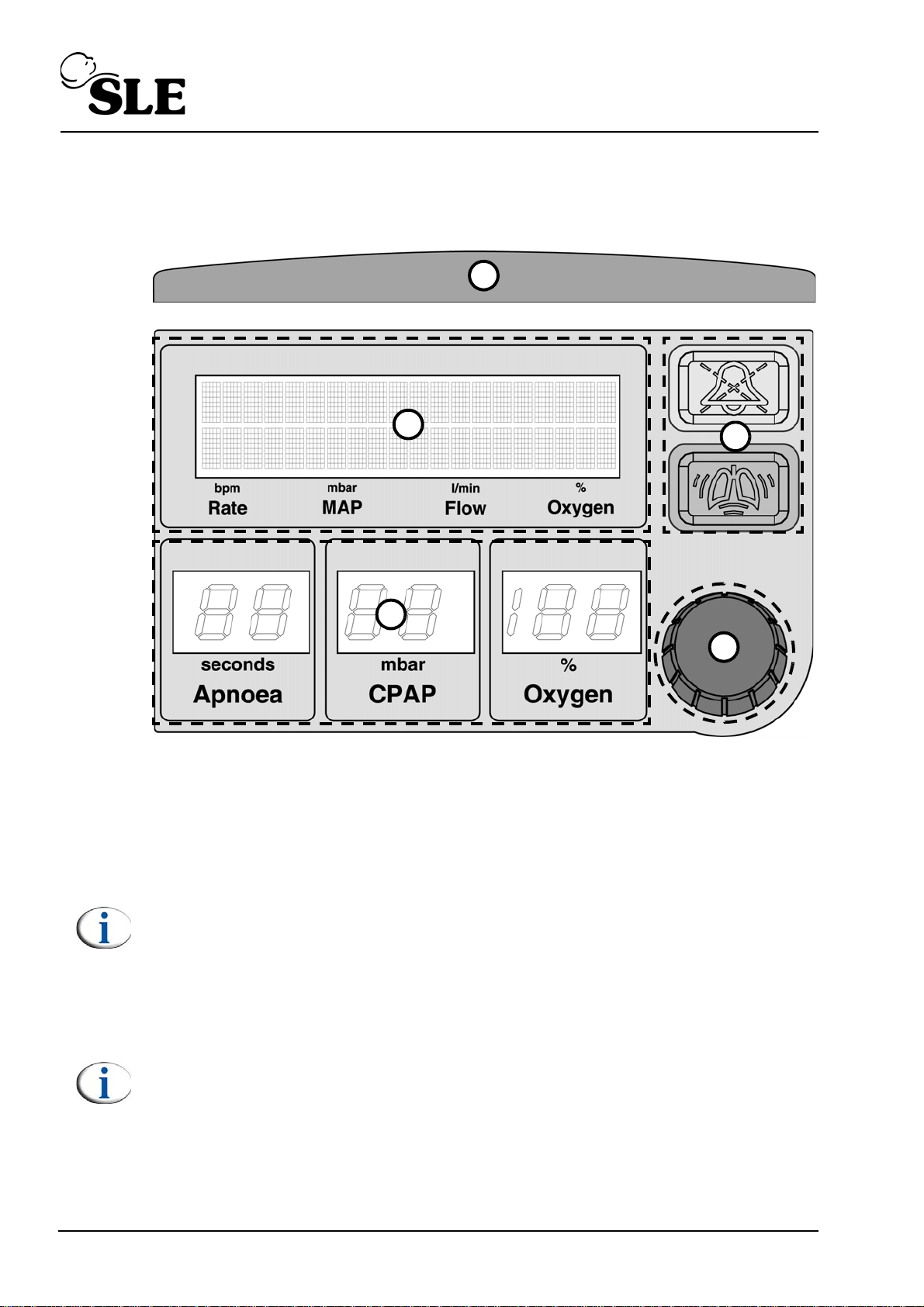
6. User interface
1
2
3
4
5
The SLE1000 user interface comprises of one LCD display (1), three LED
displays (2), one push and turn knob (3), two push buttons (4) and light bar (5).
The SLE1000 is controlled solely through items 3 and 4.
6.1 Main LCD display (1)
This display shows the measured bpm, mean airway pressure, flow, oxygen
concentration and airway pressure bar graph. It also displays the function names,
alarm messages, alarm history and battery status.
Note: The functions shown in this display are referred to as upper level
functions and display.
6.2 LED display windows (2)
The LED displays show the set values for the Apnoea alarm, CP AP pressure and
percentage oxygen.
Note: The functions shown in this display are referred to as lower level
functions.
Page 24 of 128
Page 25

6.3 Push and turn knob (3)
The push and turn knob is the sole method of selection and adjustment of driver
parameters.
6.3.1 Operation
To select a parameter rotate the knob in either direction (clockwise or anti
clockwise). Once the user has started to rotate the % Oxygen parameter will st art
to flash, continue to rotate the knob and the user will cycle through the adjustable
parameters or selectable displays (dependent on mode the user has selected).
Each display will start to flash when selected. To adjust the parameter or display
press the knob to activate and rotate to change the setting or message. When the
required setting has been set, press the knob to confirm.
Note: The selection will time-out after 8 seconds if the confirm button is not
pressed. There is also a 2 second delay between button pushes.
6.4 Audio paused and boost buttons (4)
6.4.1 Audio paused
When an alarm threshold has been crossed an alarm signal is
triggered. This consist of two components, visual and audible.
Pressing the audio paused button, mutes the audible
component of the alarm for 120 seconds.
Pressing the audio paused when no alarms are active, mutes
the unit for a period of 120 seconds. For any alarms generated within this period
only the visual component will activate.
The unit will display the text “Audio Paused” and will alternate this message with
any alarm message in an alarm condition.
Pressing the button for a second time in audio paused mode will revert the unit to
normal operation.
Note: Any latching alarms active during audio paused mode are reset on the
second press of the button. See “Latching and non latching alarms” on
page 98.
6.4.1.1 Audio paused alarm setting
In the flow mode if the button is held down for 4 seconds it sets the High leak and
Exhaust Impeded alarm thresholds ±2mbar around the delivered CP AP pressure.
6.4.2 Boost button
This delivers an up to 3 mbar of gas as long as the user holds
the button down for a maximum of 30 seconds. After 30
seconds the unit stops the boost, but the user can re-apply the
boost by repressing the boost button.
6.5 Light bar (5)
The light bar illuminates in an alarm condition. Red for high priority alarms, Y ellow
for medium priority alarms and Blue for low priority and technical alarms.
Page 25 of 128
Page 26
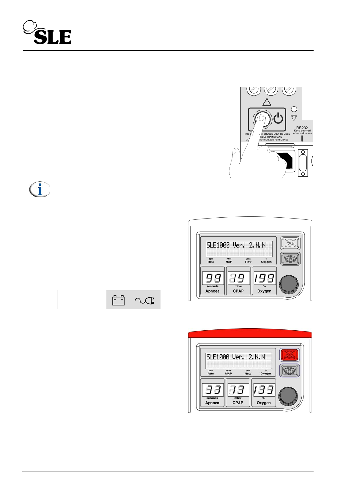
7. Operation
7.1 Power up
1. Push the power button on the rear of the
machine for 3 seconds.
Note: If the battery indicator and mains indicator lights on the front panel
are both illuminated, the unit cannot be turned on. See “Battery and mains
indicators” on page 53.
2. St art of self test by cycling the LED’ s.
The unit will sound 2 speaker tones.
This is to confirm the speaker
operation.
3. The battery low and mains
disconnected icons will flash briefly.
4. At 3 in the Apnoea display window,
the light bar and audio paused button
should become illuminated with red
LEDS.
Page 26 of 128
Page 27
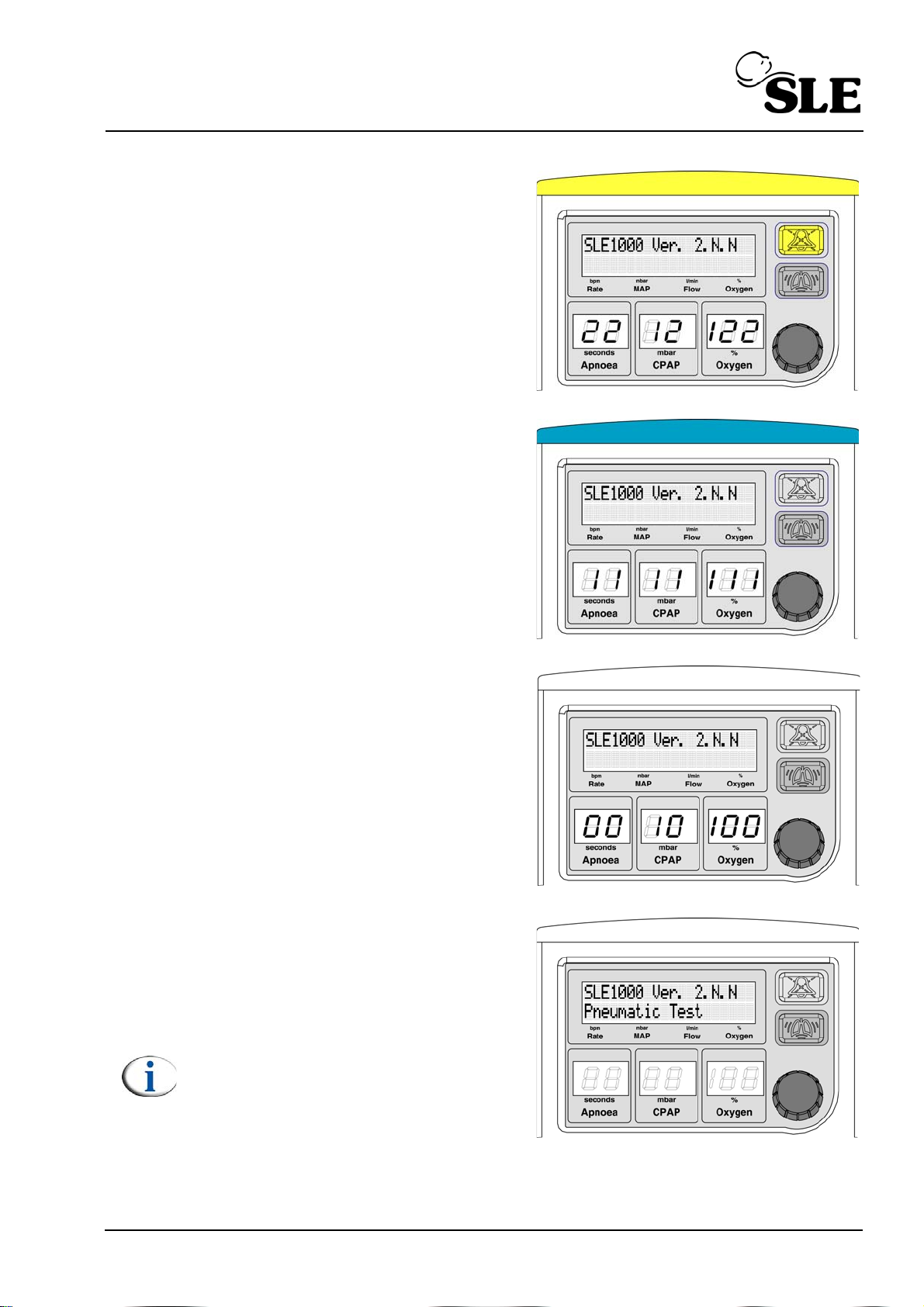
5. At 2 in the Apnoea display window
the light bar and audio paused button
should become illuminated with
yellow LEDS.
6. At 1 in the Apnoea display window
the light bar only should become
illuminated with blue LEDS
7. At 0 in the Apnoea display window
the light bar should switch off.
8. The unit will run through a self test
routine. It will start with a Pneumatic
test.
Note: Air has to be connected for the
unit to pass the pneumatic test.
Page 27 of 128
Page 28
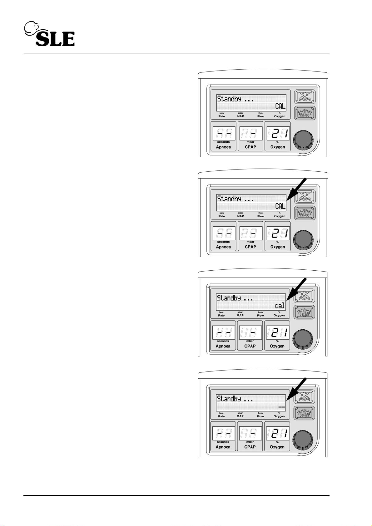
9. The unit will then enter Standby
mode.
10.The unit will now calibrate the
oxygen monitoring system, starting
with the 21% point.
This is indicated by “CAL” being
displayed in the lower right of the
LCD.
11.The unit will now calibrate the
oxygen monitoring system, starting
with the 100% point.
This is indicated by “cal” being
displayed in the lower right of the
LCD.
12.The stabilisation period for the
oxygen system is indicated by the “--”
being displayed in the lower right of
the LCD.
Page 28 of 128
Page 29
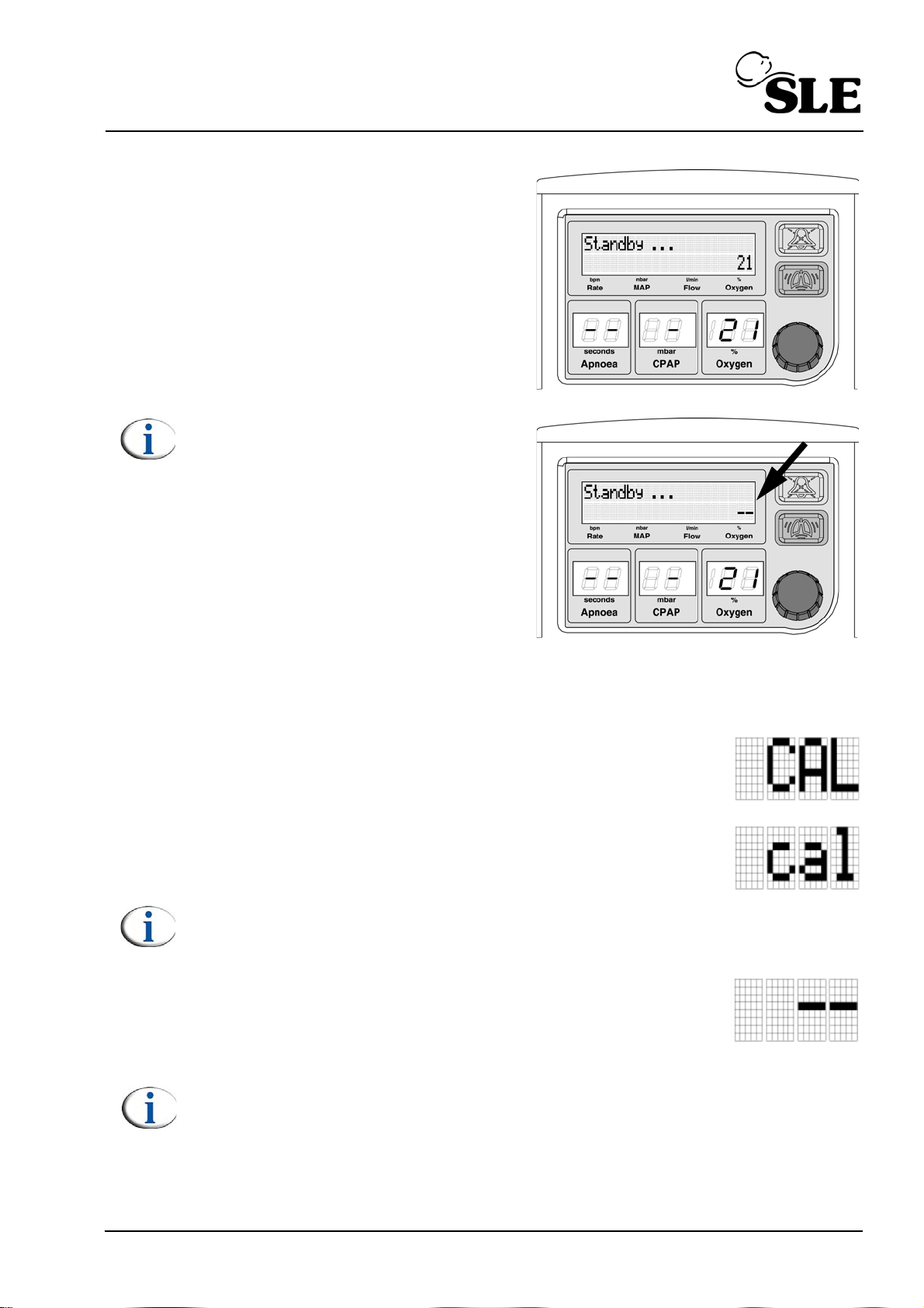
13.Once the calibration is complete the
unit will be in “Standby mode” mode
Note: If the unit is being used only
with air, the unit will display “--”. The
Oxygen control is locked to 21%. If
the user tries to select a percentage
of Oxygen greater than 21% the
message "O2 Calib Error" is
displayed.
7.2 Oxygen calibration routine description
The SLE1000 oxygen calibration routine is as follows:
The first 180 seconds after power up the unit calibrates the
system using air. The unit displays the text “CAL” in upper case
characters.
The second 90 seconds the unit calibrates the system using
100% oxygen. The unit displays the text “cal” in lower case
characters.
Note: The user can when the unit is displaying “cal” in lower case letters set
the oxygen percentage.
The following 30 seconds the unit displays “--” as the unit allows
the oxygen monitoring system to stabilize.
Note: If the unit is being used with air only the “--” will not be replaced by
the measured value of percentage of oxygen. In standby mode the “O2
Calib Error alarm” will not trigger. The user will not be alerted to the
calibration failure until either CPAP or Flow mode is selected. The user will
then cancel the alarm accepting air only use.
Page 29 of 128
Page 30
Warning: If the unit is connected to Oxygen and the “O2 Calib Error alarm”
is triggered when entering either CPAP or Flow mode. Manually calibrate
the 100% oxygen point in either CPAP or Flow mode. If the “O2 Calib Error
alarm” is re-triggered remove the unit from service.
The unit will then display 21% oxygen and the user can now set
required percentage.
Note: In the first 4 hours the SLE1000 performs an adaptive calibration
routine. If the unit detects that the measured is lower than the set by 3%
then it forces a recalibration of the 100% oxygen. The unit will recheck the
difference every 8 minutes within the first four hours of operation.
Note: If the unit detects that the measured and set differ by ± 5% it
generates the “High Oxygen” or “Low Oxygen” alarm. In this instance the
user can manually recalibrate the 100% oxygen. See “100 % O2 Calibration”
on page 40. This check is not limited to the first four hours of operation.
The unit automatically recalibrates the oxygen every 8 hours unless a calibration
error has occurred, (i.e. using the SLE1000 with air only) then the unit calibrates
every hour.
Note: If the SLE1000 is started using only air, the user can connect the
oxygen supply at any time, but will have to manually calibrate the oxygen
system.
Warning: If the oxygen supply fails after calibration whilst set to 21%
oxygen the unit will not alarm. The " No Oxygen Supply" alarm will only
become active when the user tries to set a percentage of oxygen above
21%.
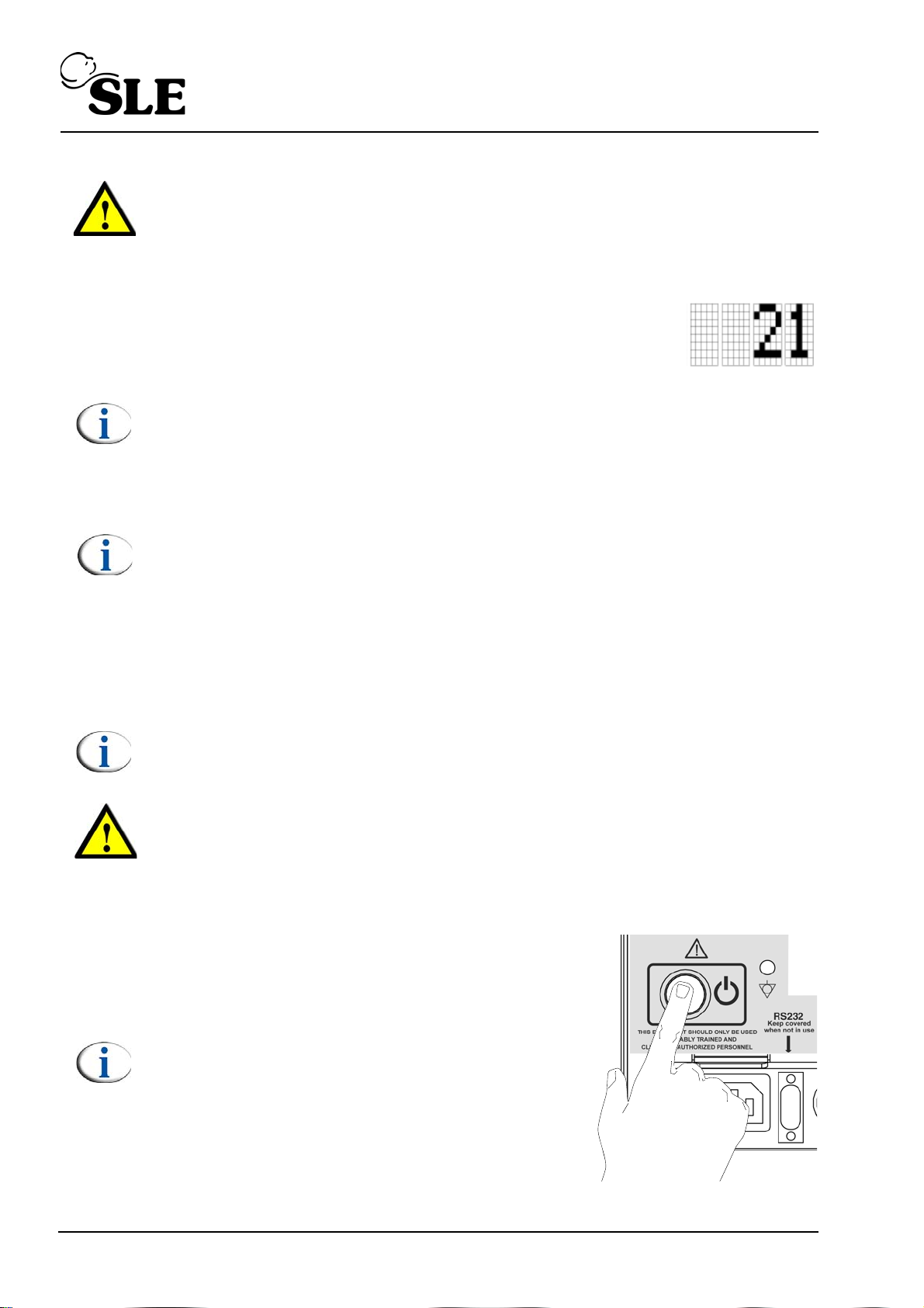
7.3 Power down
Push and hold the power button on the rear of
the machine for 3 seconds. Re-press the
button to cancel the complete power fail
alarm.
Note: The unit can be turned on again after
3 seconds.
Page 30 of 128
Page 31
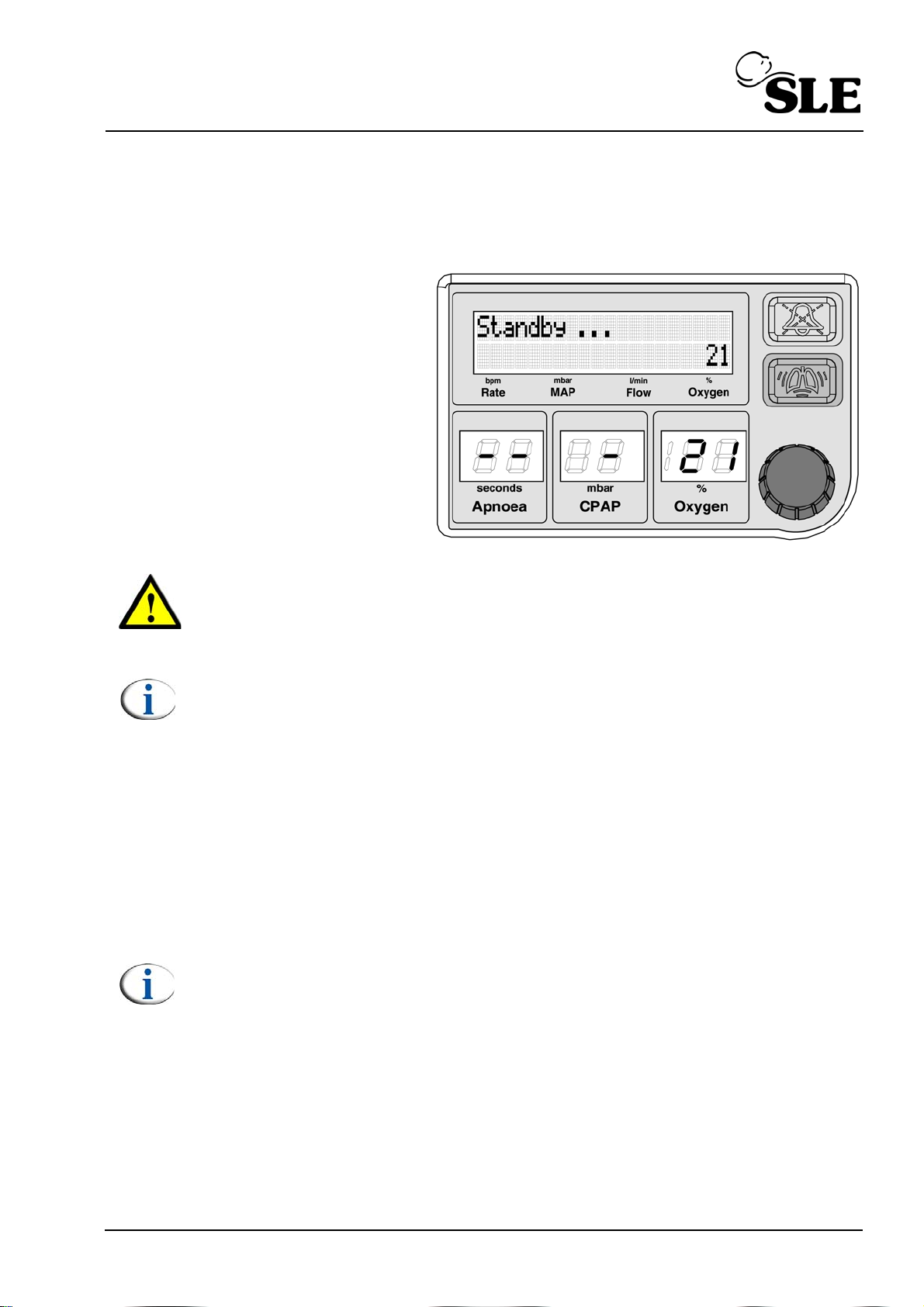
8. Standby mode
On power up the unit enters “S t andby” mode. In “Standby” mode the unit reduces
the flow to less than 2 l/min.
Stand-by mode is indicated
in the CP AP LED display by
one horizontal dash “-”.
The LCD displays
“Standby...”.
Warning: The patient must never be connected to the unit in “Standby”
mode. The unit does not deliver any therapeutic flow in this mode and all
patient and gas alarms are disabled with the exception of the "Battery Low"
alarm.
Note: In standby mode the user can only select the "% Oxygen", "CPAP",
"Apnoea" and "Set Flow"
8.1 Exiting Standby mode
The user has three routes to exit standby mode.
A. Selecting a CPAP pressure.
B. Selecting a flow of 6 l/min (or if a flow has already been set the last set flow).
C. Selecting a flow directly.
Note: Please see the “CPAP and Flow mode” chapter for a detailed
description on page 55.
Page 31 of 128
Page 32
9. Selecting a parameter, display or calibration function
9.1 Upper and lower level functions.
The following is a the list of selectable parameters using the control knob:
Set Oxygen Level Parameter - lower level function
Set CPAP level Parameter - lower level function
Set Apnoea Time Parameter - lower level function
Set Trigger Sen. (Sen. = Sensitivity) Parameter - upper level function
Show Batt. Level (Batt = Battery) Display function - upper level function
Start O2 Calib (Calib = Calibration) Calibration function - upper level function
Show Alarm Hist. (Hist. = History) Display function - upper level function
Set Flow Parameter - upper level function
9.1.1 Selecting lower level functions
Oxygen %, CPAP, Apnoea and Set Flow values (Lower level functions)
Note: Please see the “CPAP and Flow mode” chapter for a detailed
description on page 55.
Note: If the user is in Standby mode, they can only select one of the
following parameters % Oxygen, CPAP, Apnoea and Set flow.
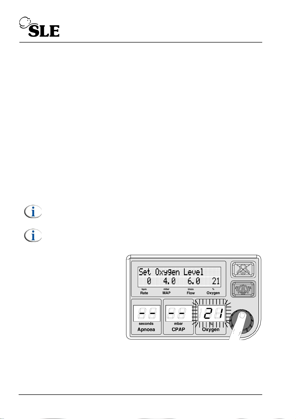
The procedure is the same
for all the settable
parameters.
Push or turn the knob.
The Oxygen parameter will
start to flash.
Page 32 of 128
Page 33
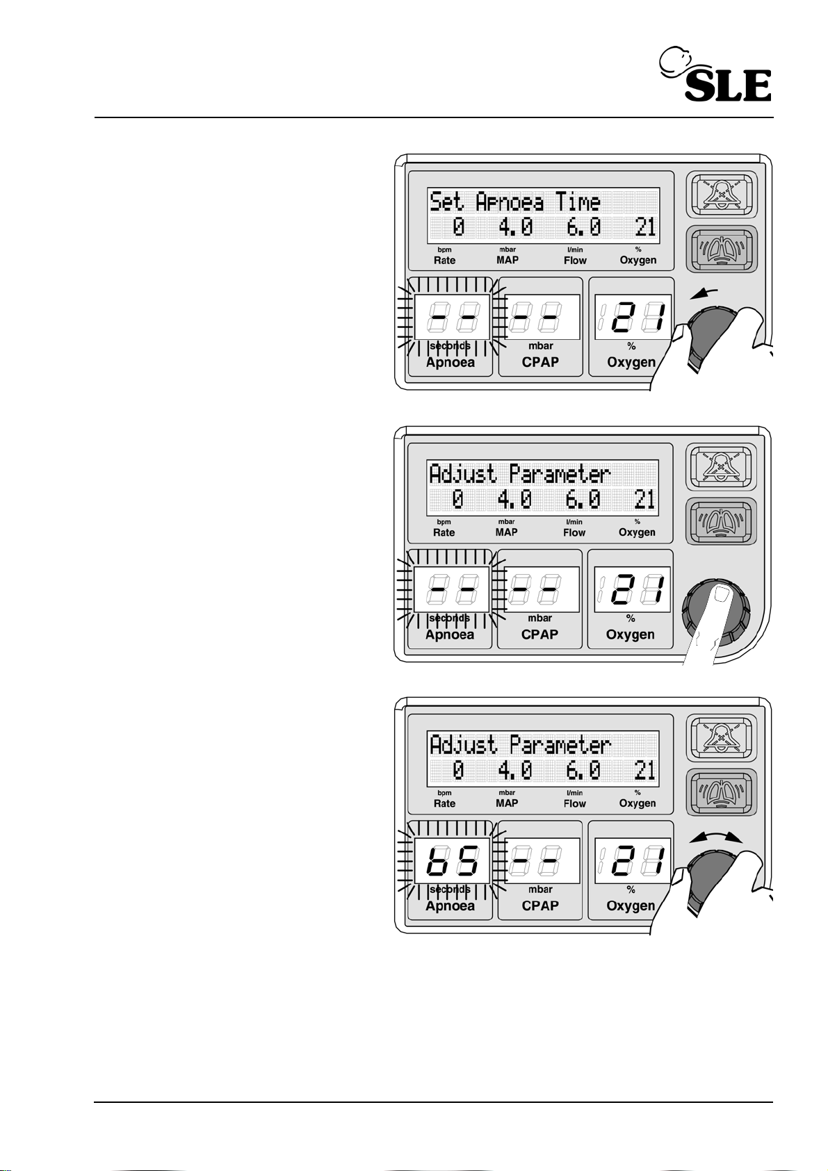
Rotate the knob to the left to
cycle through the selectable
parameters, displays or
calibration functions.
The screen will display the
title of the parameter that
can be adjusted.
Push the knob to adjust the
flashing parameter.
The LCD display changes
from “Set Apnoea time” to
“Adjust Parameter”.
Rotate the knob to change
the set parameter value.
Page 33 of 128
Page 34
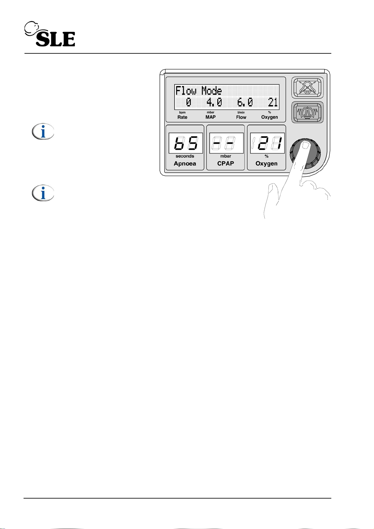
Push the knob to confirm
the setting. The LCD
display will return to
displaying “Flow Mode”.
Note: If the unit is
delivering CPAP then the
Cycle indicator bargraph
is displayed. See section
12.1 on page 51.
Note: Failure to push the
knob to confirm the
setting will cause the set
value to be discarded
after 8 seconds.
Page 34 of 128
Page 35
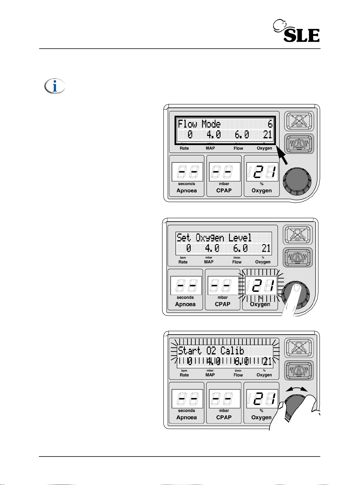
9.1.2 Selecting upper level functions
Note: For the user to select an upper level function the unit will have to be in
either "Flow Mode" or "CPAP" mode.
The procedure is the same
for all the settable functions
or displays..
The display messages are
located in the LCD window.
Push or turn the knob.
Rotate the knob until the
upper line of text starts to
flash.
Page 35 of 128
Page 36
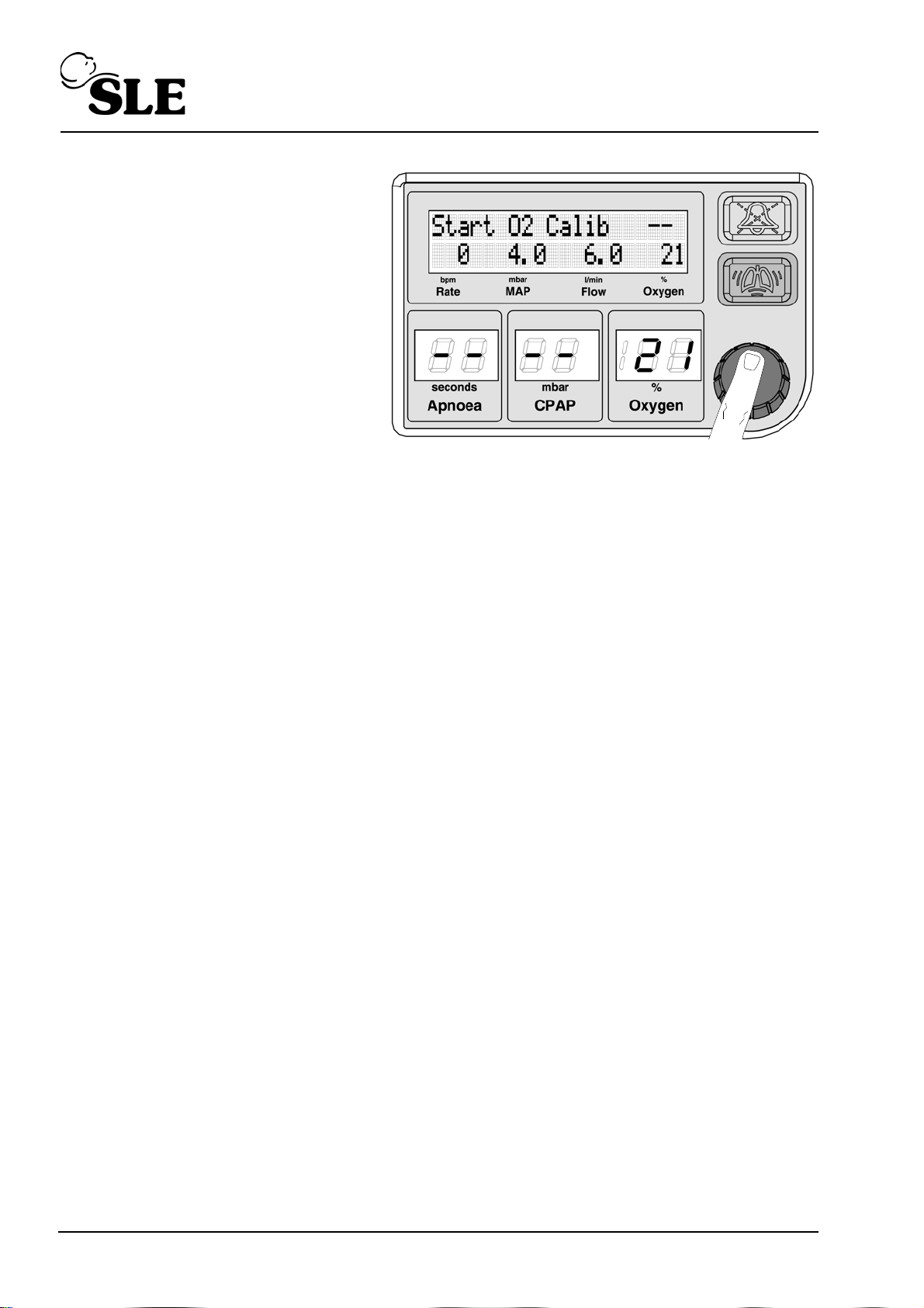
Push the knob to select.
Page 36 of 128
Page 37
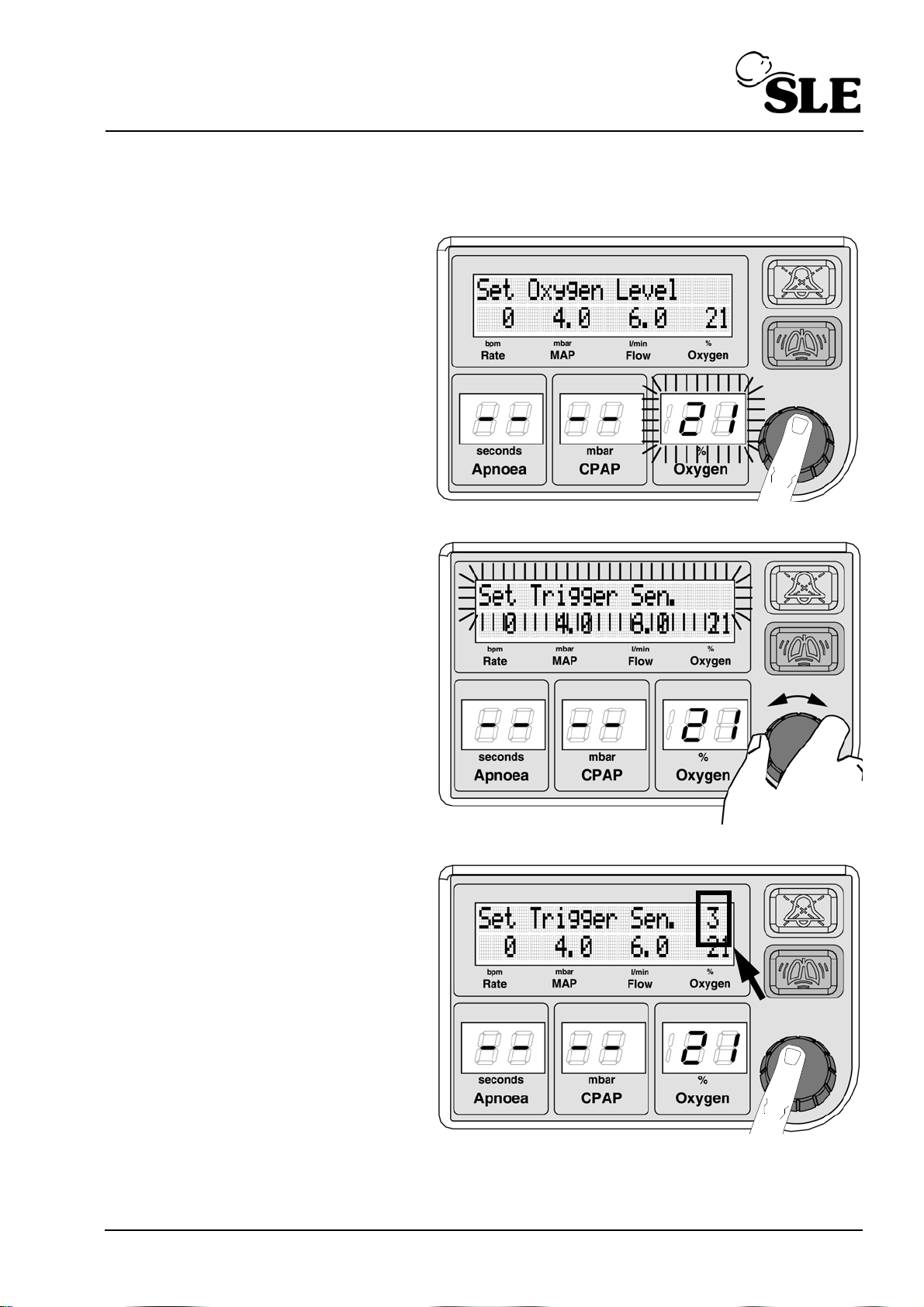
9.2 Upper level functions, displays and parameters
9.2.1 Pressure trigger sensitivity
Push or turn the knob.
Rotate the knob until the
text “Set Trigger Sen.”
appears and starts to flash.
Push the knob to select.
The default value of 3 is
displayed.
Page 37 of 128
Page 38
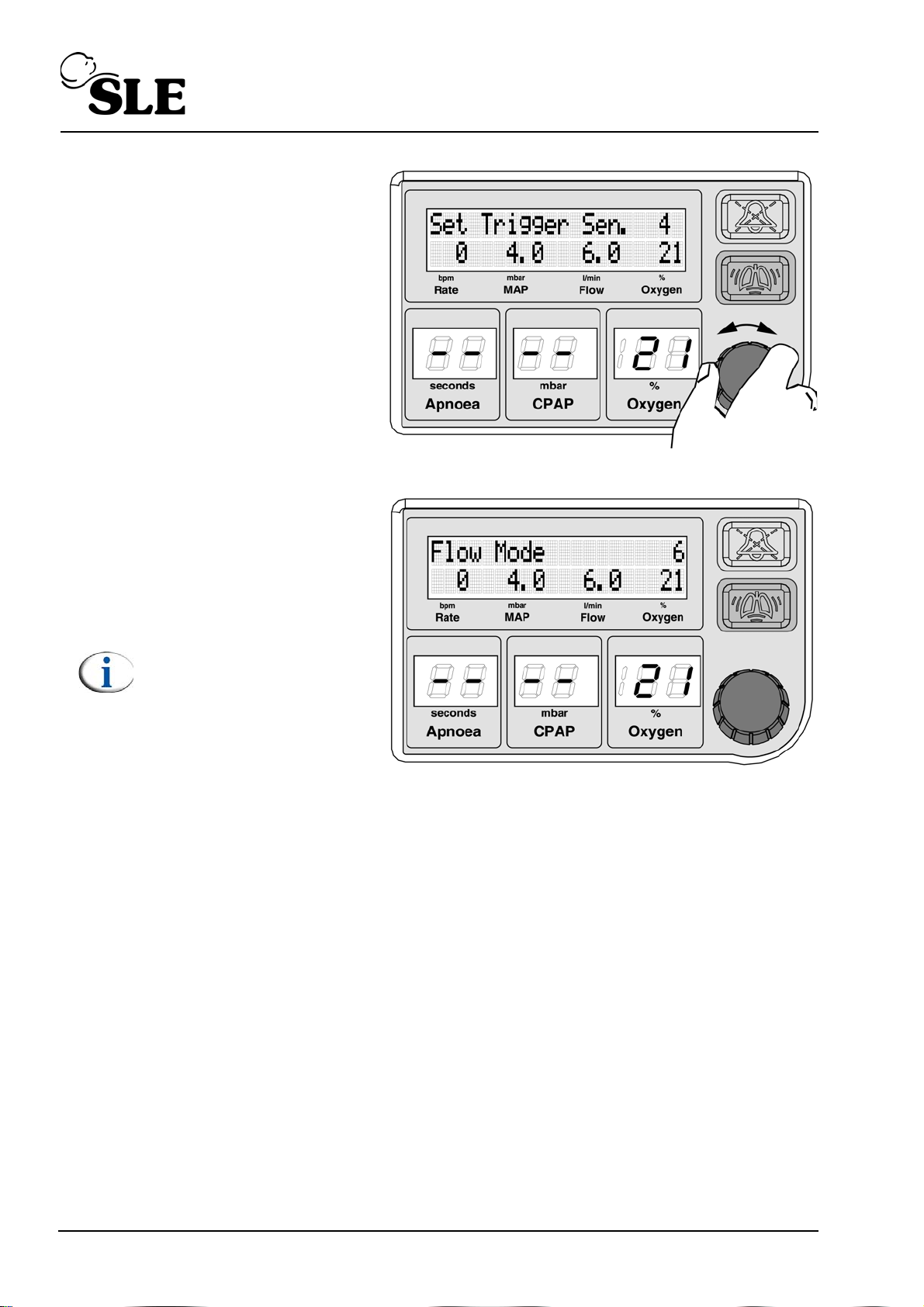
Rotate the knob to
increase or decrease the
valve.
The trigger sensitivity has a
range of 1 to 6, with the
default being 3.
1 being least sensitive.
6 being most sensitive.
Push the knob to select the
new sensitivity setting. The
unit display returns to the
Flow mode.
Note: If the unit is
delivering CPAP then the
cycle indicator bargraph
is displayed. See section
12.1 on page 51.
Page 38 of 128
Page 39
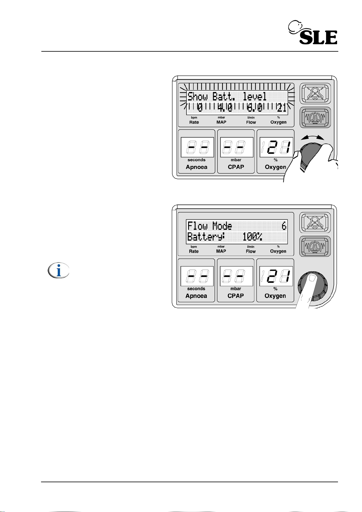
9.3 Showing battery charge level
Rotate the knob to select
the “Show Batt. level” and
starts to flash.
Push the knob and the
battery charge level will be
displayed.
Push the knob to return to
the default display.
Note: The battery level
times out after 8 seconds.
Page 39 of 128
Page 40
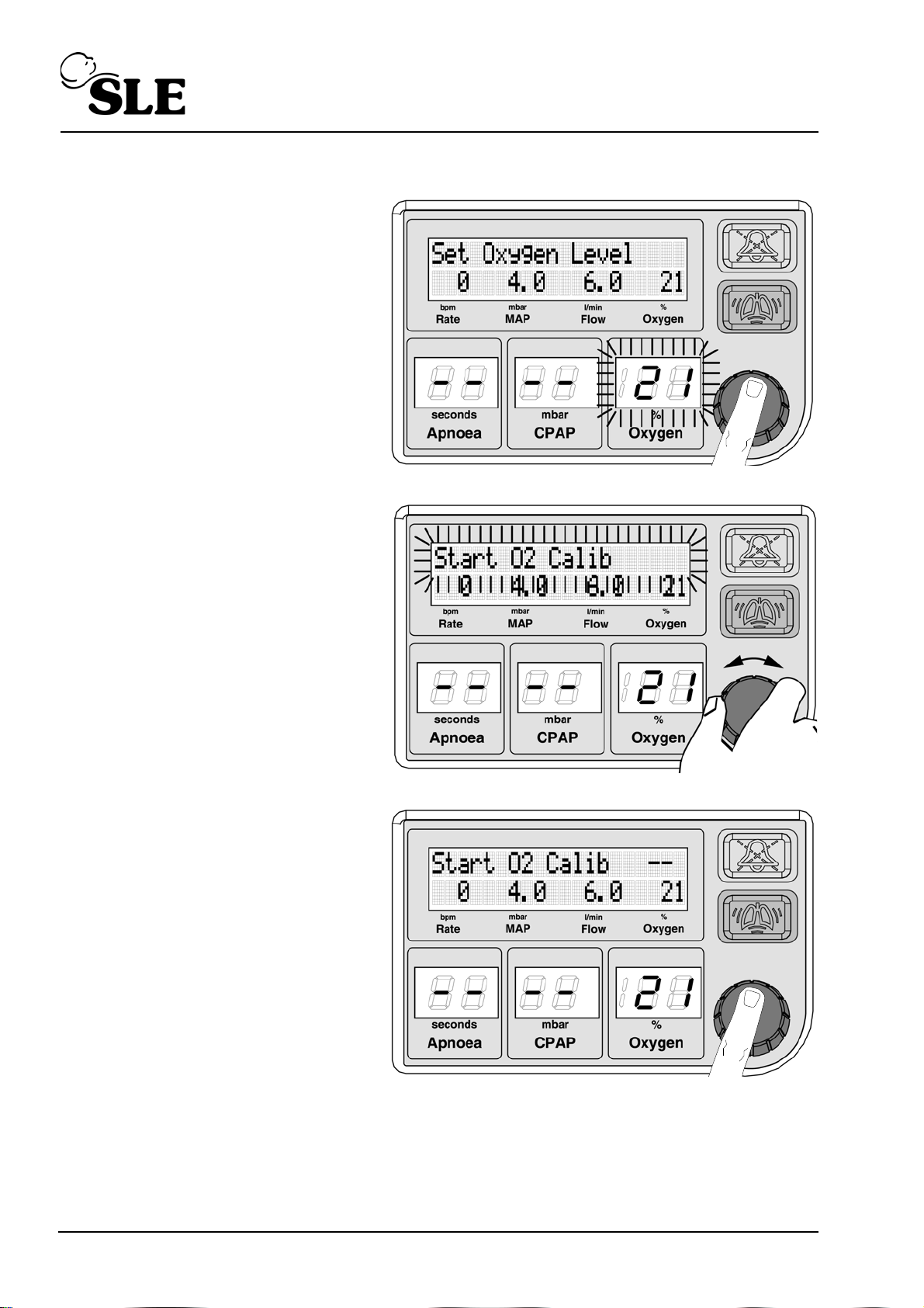
9.3.1 100 % O2 Calibration
Push or turn the knob.
Rotate the knob until the
text “Start O2 Calib”
appears and starts to flash.
Push the knob to select.
Page 40 of 128
Page 41
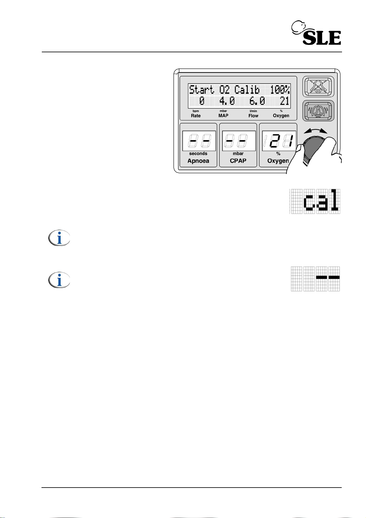
Rotate the knob to select
the 100% Oxygen
calibration routine.
Push the knob to start the 100% Oxygen calibration routine. The
unit display returns to the Fixed Flow mode but displays the
word “cal” in the measured percentage of Oxygen area. (See
“Oxygen calibration routine description” on page 29.)
Note: If the unit is delivering CPAP then the Cycle indicator bargraph is
displayed. See section 12.1 on page 51.
Note:If the unit has been setup to operate with air only the
100% oxygen calibration will time out after 3 minutes. The
unit will return to displaying “--”. No alarms will be
generated.
Page 41 of 128
Page 42
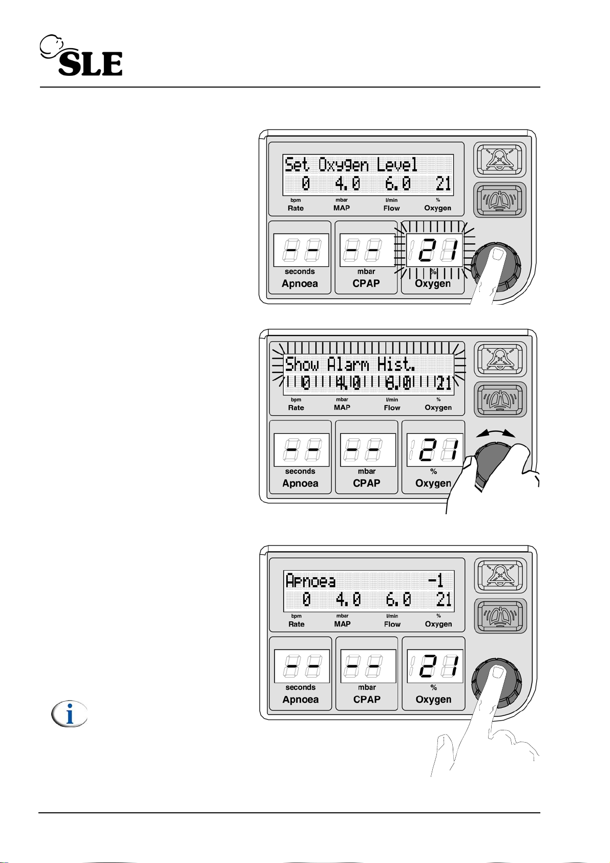
9.4 Alarm history
Push or turn the knob.
Rotate the knob until the
text “Show Alarm Hist.”
appears and starts to flash.
Push the knob to select.
The most recent alarm to
be generated will be
displayed. This is indicated
by -1.
The alarms are tagged -1 to
-25, -1 being the most
recent.
Note: As a new alarm is
generated the last alarm
is deleted and all the
existing alarms move up
in ranking.
Page 42 of 128
Page 43
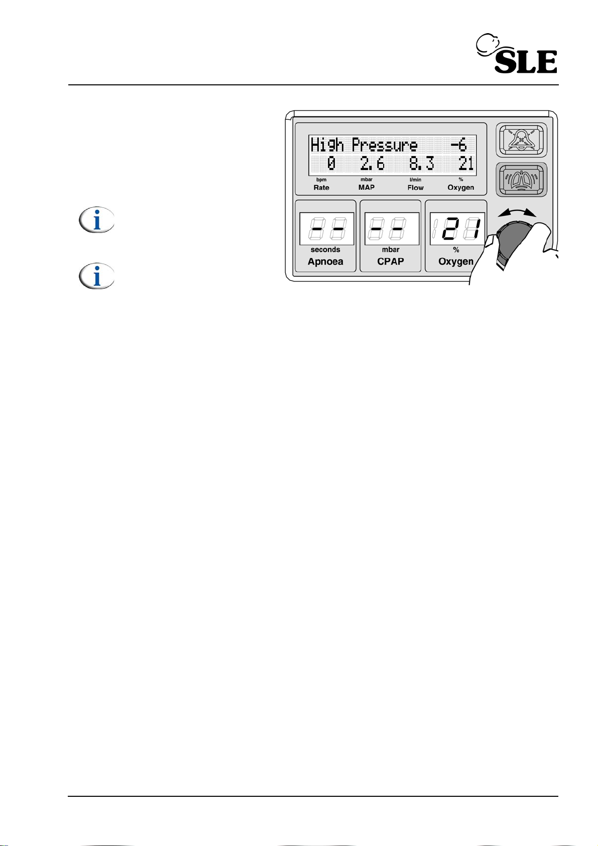
Rotate the knob to scroll
through the last 25 alarm
messages.
Push the knob to return to
the default display.
Note: The alarm history
times out after 6 seconds.
Note: The alarm history is
cleared when the unit is
turned off.
Page 43 of 128
Page 44
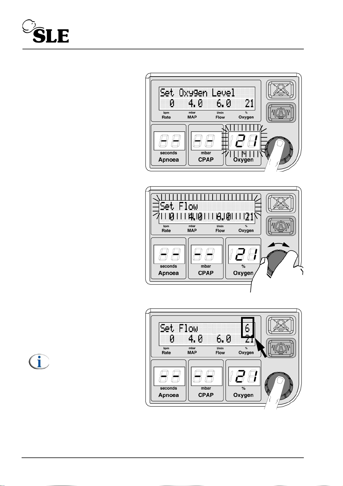
9.5 Set Flow
Push or turn the knob.
Rotate the knob until the
text “Set Flow.” appears
and starts to flash.
Push the knob to select.
The default flow value of 6
l/min will be displayed in the
right hand corner.
Note: If a Flow value has
already been set during
the session the unit will
use this value.
Page 44 of 128
Page 45
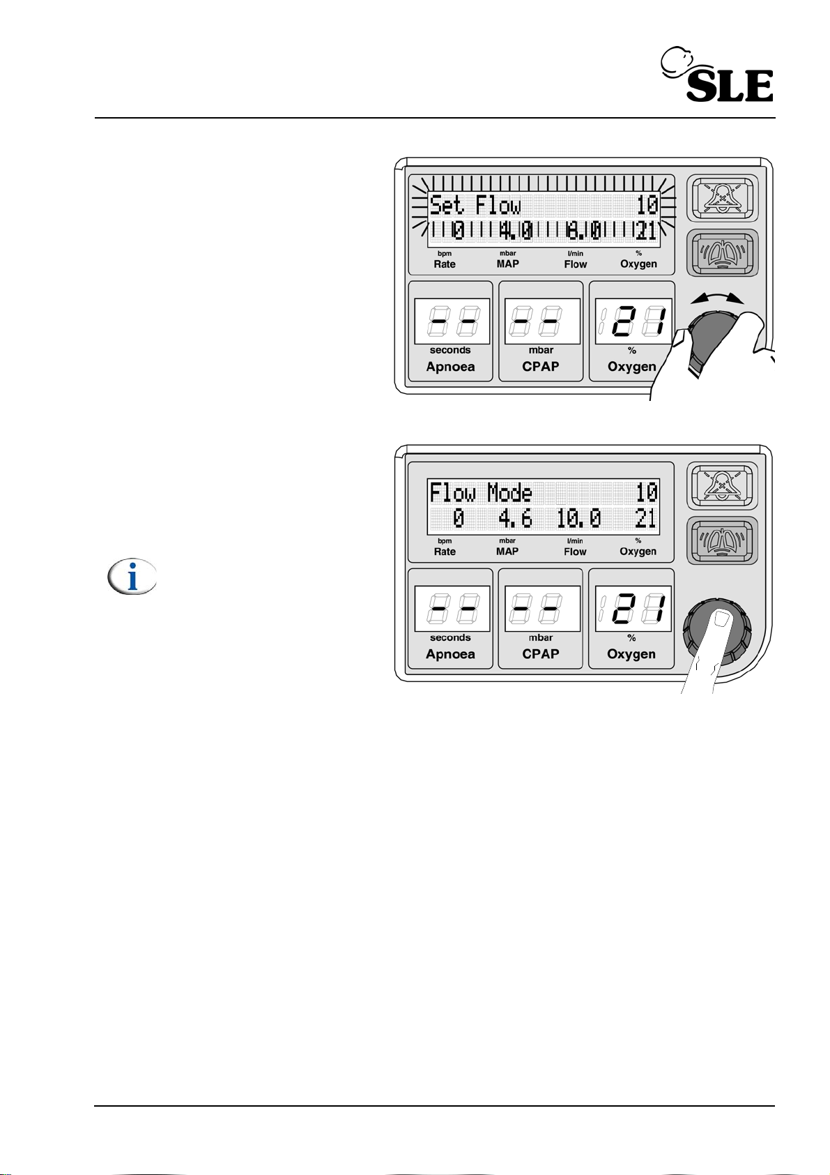
Rotate the knob to select
the required flow.
As the flow value is changed
the text will flash.
Confirm the setting.
The unit will enter flow
mode.
Note: Please see the
“CPAP and Flow mode”
chapter for a detailed
description on page 55.
Page 45 of 128
Page 46
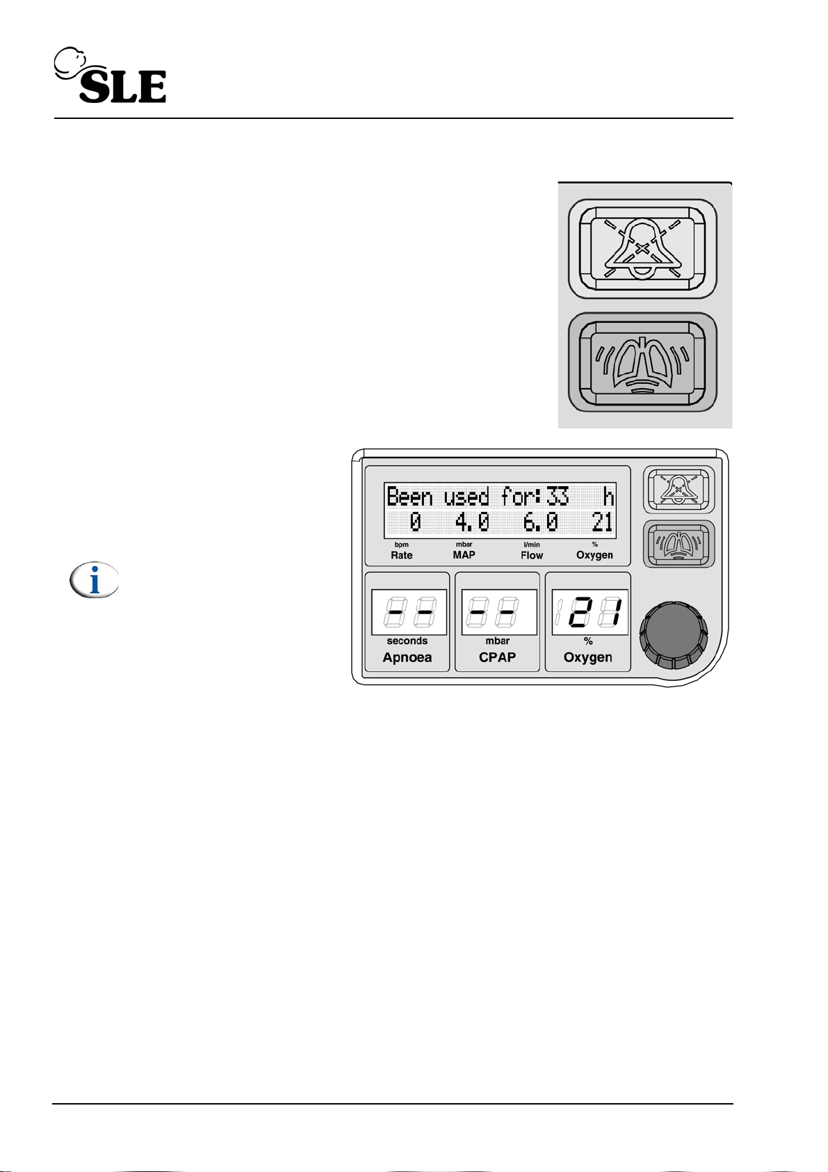
9.6 Elapsed time counter
The SLE1000 has an hour counter which records the
total elapsed in use time.
To access the display, press the “Audio paused” and
“Boost” buttons together.
The text “Been used for: N
h” will be displayed.
Press mute button to cancel
the display.
Note: The “Been used for
h” does not time out.
Page 46 of 128
Page 47
10. Audio mute button
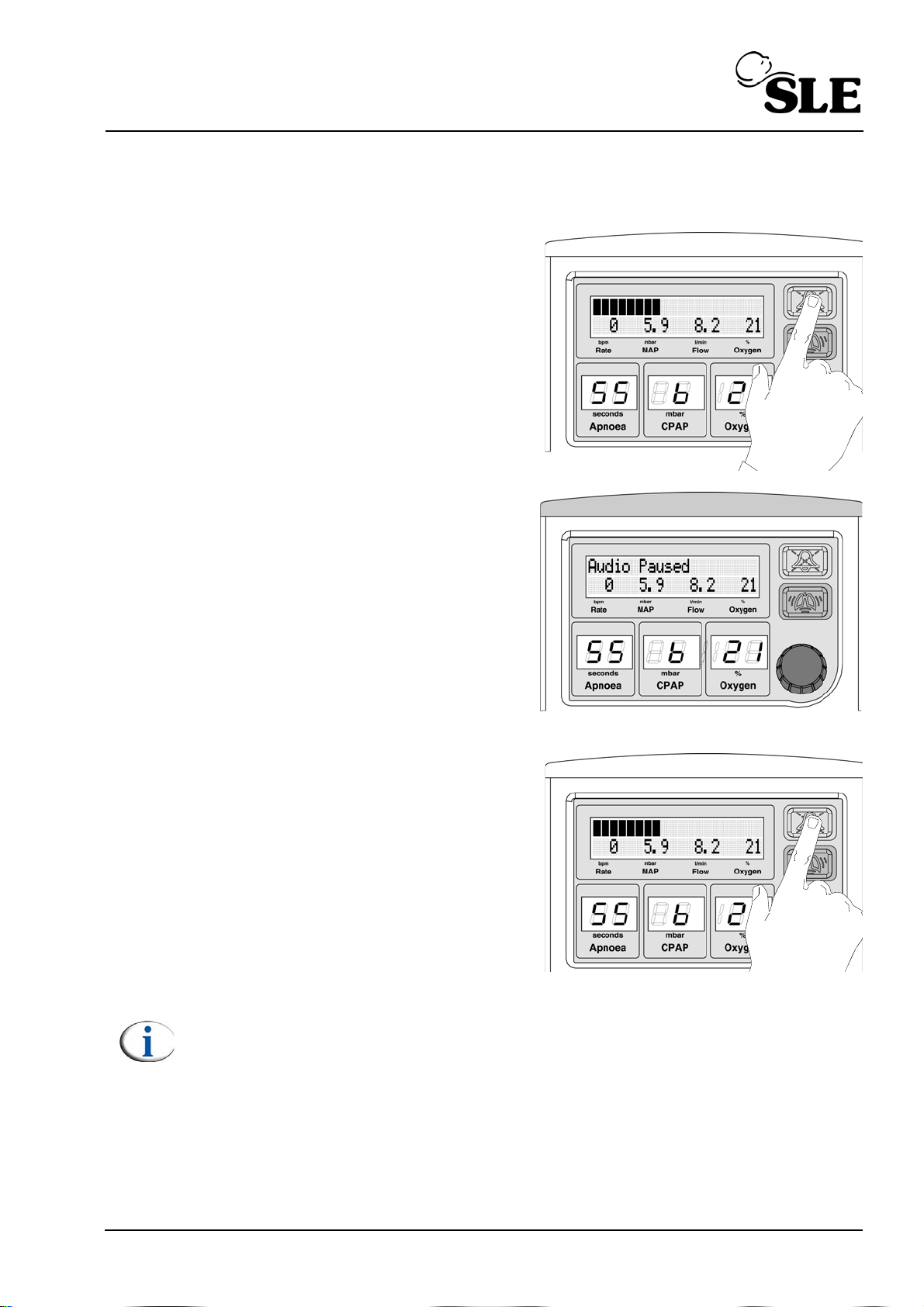
10.1 Pre-mute
The user has the ability to pre-mute the
alarm system.
The user pushes the audio paused
button once.
The unit will alternate between the text
“Audio Paused” and the cycle indicator
bargraph.
The unit will flash the light bar (Blue)
when the text “Audio Paused” is
displayed.
The pre-mute will last for two minutes.
The user can cancel the pre-mute by repressing the audio paused button.
Note: Any alarms that are generated during the pre-mute period will only be
able to initiate the visual component (i.e. the alarm bar and alarm message.)
The alarm message will alternate between the alarm message text and the
audio paused text.
Page 47 of 128
Page 48
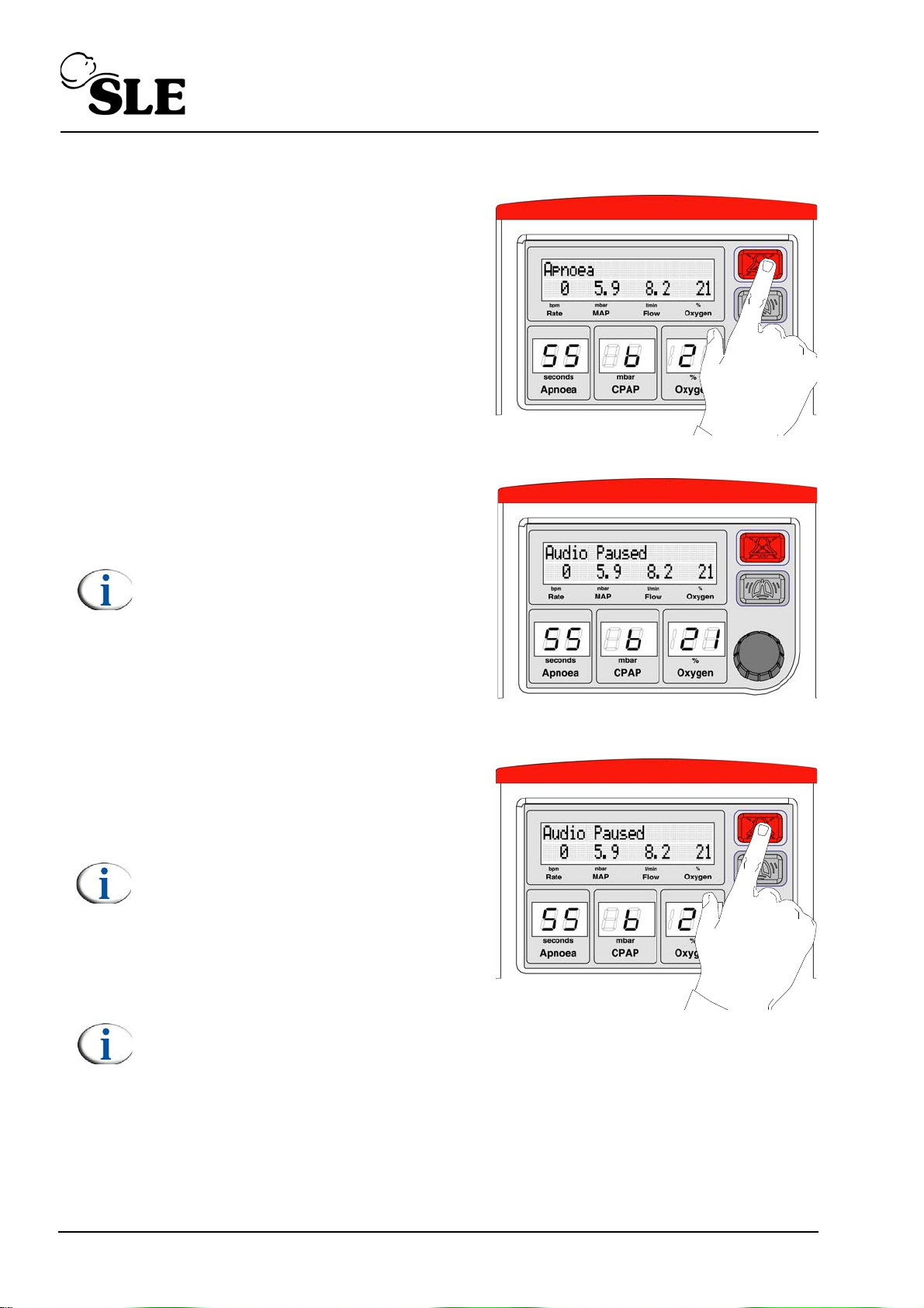
10.2 Audio paused
The user has the ability to mute the
alarm system.
When an alarm has been triggered, the
user pushes the audio paused button
once.
The unit will display the text “Audio
Paused”.
Note: The alarm message will
alternate between the alarm message
text and the audio paused text.
The mute will last for two minutes. The
alarm message will alternate with audio
paused message.
The user can cancel the mute by repressing the audio paused button.
Note: Any latching alarms active
during audio paused mode are reset
on the second press of the button.
See “Latching and non latching
alarms” on page 98.
Note: The user needs to be aware that
the “Mains disconnect”, “No oxygen
supply” and “O2 Calib. Error” alarms
will not re-instate.
This is because the unit can operate
on battery power and on air only.
Page 48 of 128
Page 49
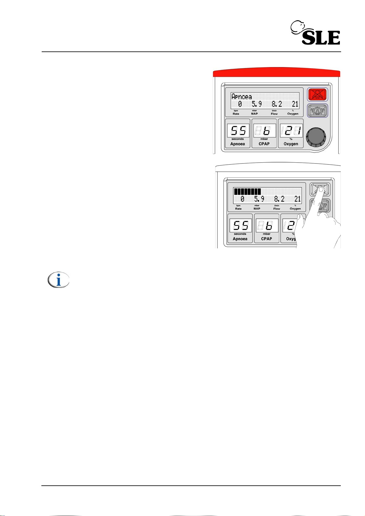
If the alarm condition has not been
cleared then the alarm will be reinstated.
If the alarm condition has been cleared
the SLE1000 returns to CPAP mode.
Note: The audio mute button has a third function of setting alarm
thresholds in flow mode. See page 67.
Page 49 of 128
Page 50
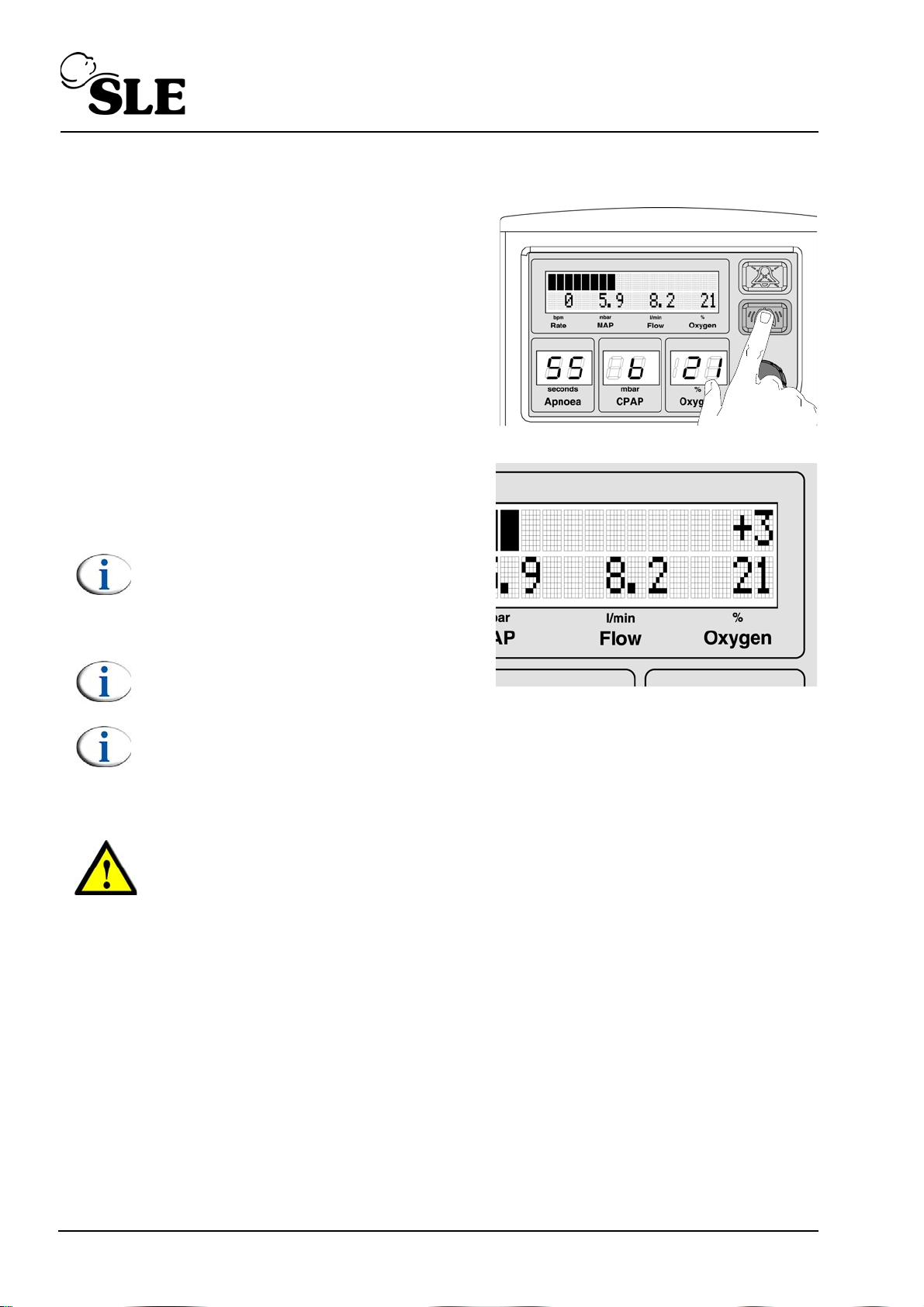
11. Boost button
The boost button delivers an up to 3
mbar above the measured flow.
The boost is maintained whilst the button
is pressed, up to 30 seconds.
The boost is delivered at the set Oxygen
percentage.
In the main display the text +3 is
displayed.
Note: The Boost button will time out
after 30 seconds. This is a safety
feature. The user can re-apply the
boost if required by releasing and
repressing the Boost button.
Note: The Boost button has minimal
effect between 10 - 12 mbar.
Note: On pressing the boost button the patient trigger detection is
suspended for 5 seconds
Warning: When the set pressure is 11 or 12 mbar and the user applies the
boost, the delivered pressure might go above 15.5 mbar momentarily and
trigger the "High Pressure" alarm. If the alarm is triggered this will cut of
the gas supply for 5 seconds. See “Alarm messages and sounds.” on
page 98.
Page 50 of 128
Page 51
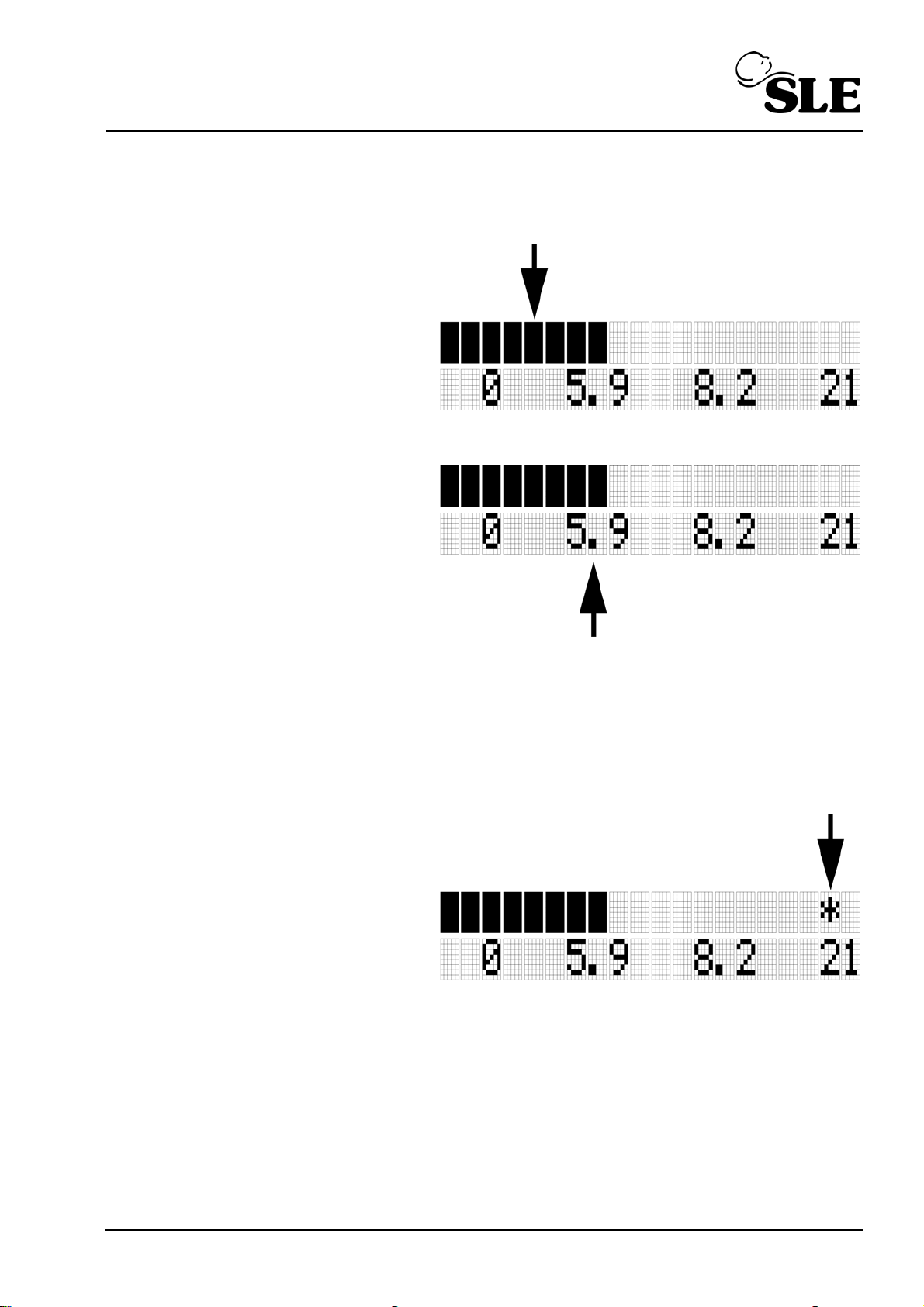
12. Indicators
12.1 Cycle indicator bargraph
When the SLE1000 is
delivering CPAP the LCD
displays a airway pressure
bargraph. The bargraph is
an indication of breath
cycling (mechanical or
patient).
The bargraph has a span of
±2.5 mbar around the
measured mean airway
pressure.
The decimal point in the
measured mean airway
pressure reading denotes
the centre point the
bargraph
The bargraph gives a visual
indicator to breath cycling.
12.2 Breath detection
When the SLE1000
registers inspiratory effort
from the patient it displays a
star character in the upper
left line of the LCD display.
Page 51 of 128
Page 52
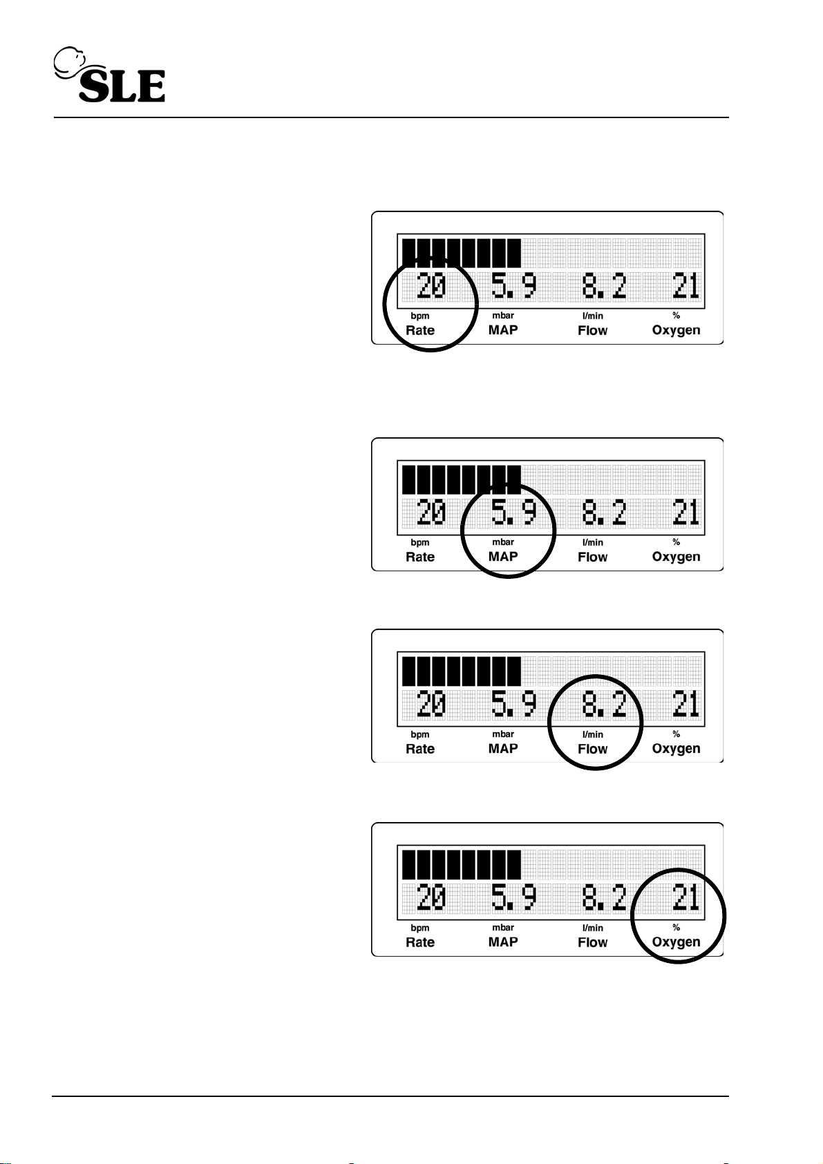
12.3 Averaged value
12.3.1 BPM
The BPM is an averaged value
from a 30 second rolling
window.
12.4 Measured values
12.4.1 MAP
The Mean Airway Pressure
(MAP) is a measured value in
mbar.
12.4.2 Flow
The Flow is a measured value
in l/min.
12.4.3 Oxygen
The % oxygen is a measured
value of the fraction of inspired
O2.
Page 52 of 128
Page 53

12.5 Battery and mains indicators
12.5.1 Battery indicator
The battery icon will illuminate when battery drops to 10% or less of the
full charge level. It is accompanied by a audible and visual alarm. The
icon will flash whilst the battery is charging (less than 100%).
12.5.2 Mains disconnect indicator
The mains disconnect icon will illuminate when mains power is
unavailable. The icon remains illuminated until mains power is
restored. It is accompanied by a audible and visual alarm.
Note: If both the battery indicator and mains icon flash when the power
button is depressed the battery is depleted, the user will be unable to restart
the unit until mains power has been restored.
12.6 Power related faults
12.6.1 With mains power connected
If both the battery and mains indicator lights are flashing, this indicates that there
is a hardware fault. The unit should be removed from service.
Note: If the battery icon is illuminated and fixed the battery has failed or has
been disconnected.
12.6.2 With mains power disconnected
If both the battery and mains indicator lights are flashing whilst pressing the mains
power on button, the main battery is completely discharged. The user will not be
able to start the device on battery power . Connect mains power and allow the unit
to charge the battery for 8 hours. It is not recommended that the unit be used on
battery power when mains power is available. The purpose of SLE1000 battery is
to allow continued operation in the event of a mains power failure.
Warning: If the unit has shutdown due both mains power being
disconnected and battery depletion, the user will be unable to restart the
unit until mains power has been restored.
Page 53 of 128
Page 54

This page is intentionally blank.
Page 54 of 128
Page 55

CPAP & Flow mode
Page 55 of 128
Page 56
13. CPAP & Flow mode
This chapter describes in detail the procedure of selecting either CPAP or Flow
mode.
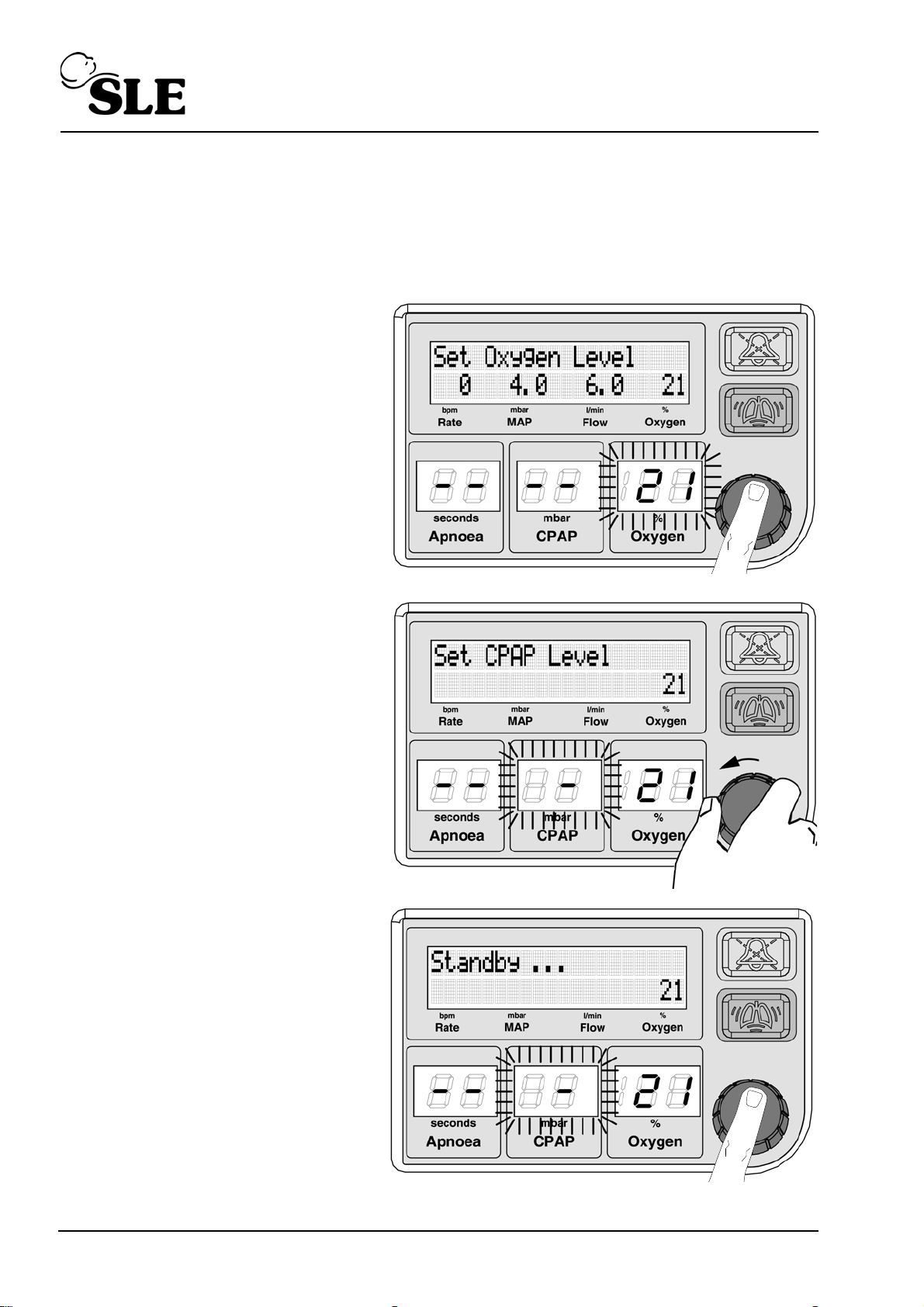
13.1 Standby to Flow mode
Push the knob.
The Oxygen parameter will
start to flash.
Rotate the knob to the left to
the CPAP parameter.
Push the knob to select the
parameter.
The display reverts to
"Standby...".
Page 56 of 128
Page 57
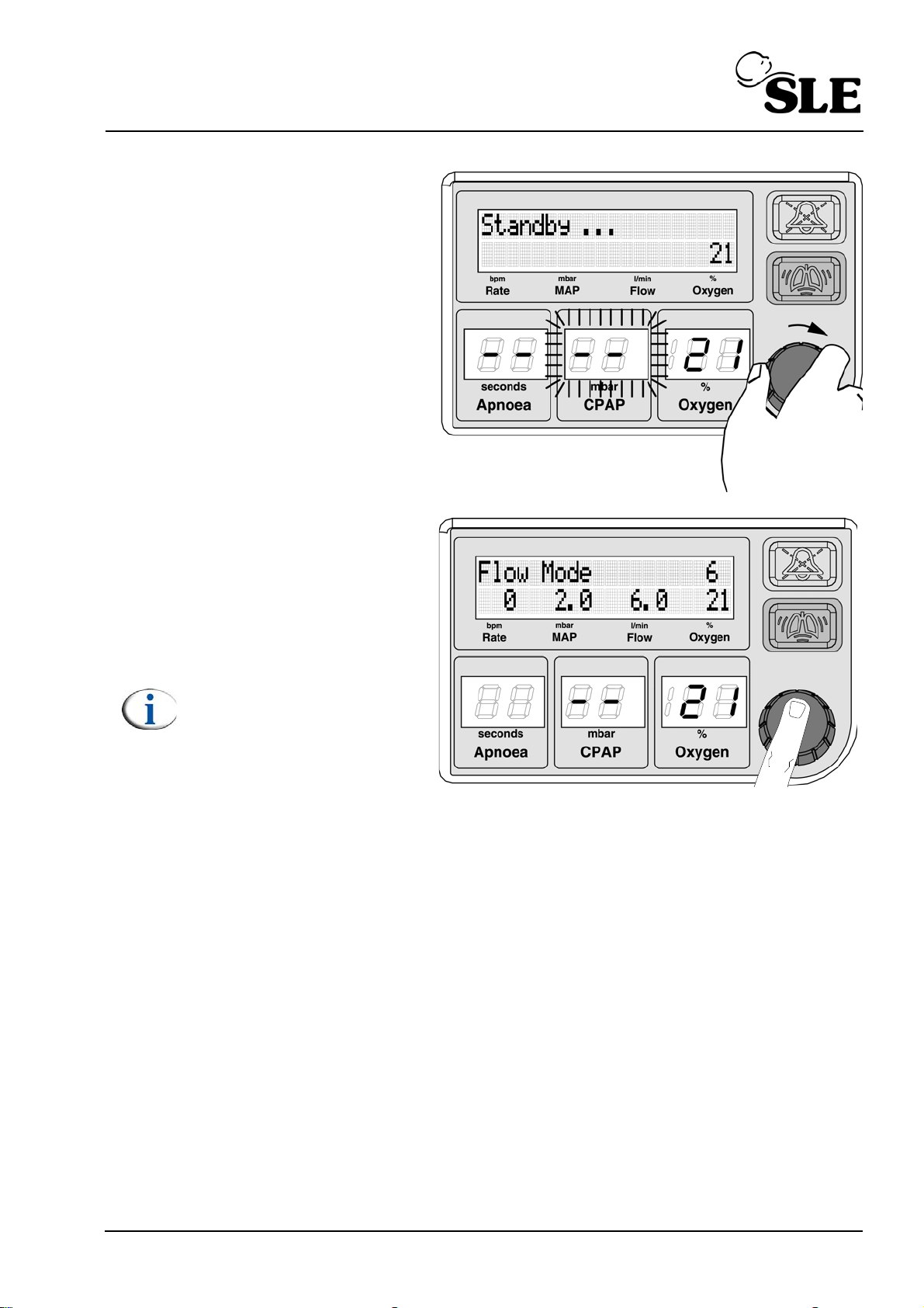
Rotate the knob to the right
to set the control to the “--”
Push the knob to confirm
the setting.
The unit will enter "Flow
Mode" mode (set at 6 l/min).
Note: If a Flow value has
already been set during
the session the unit will
use this value.
Page 57 of 128
Page 58
13.2 Setting a flow in flow mode
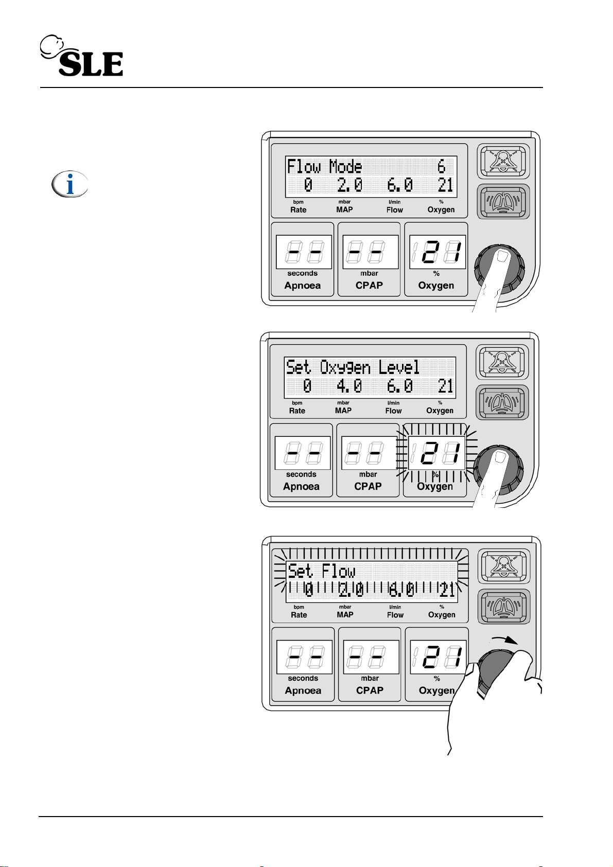
Push the knob.
Note: The default value of
6 l/min is used.
The Oxygen parameter will
start to flash.
Rotate the knob to the right
to select "Set Flow".
Page 58 of 128
Page 59
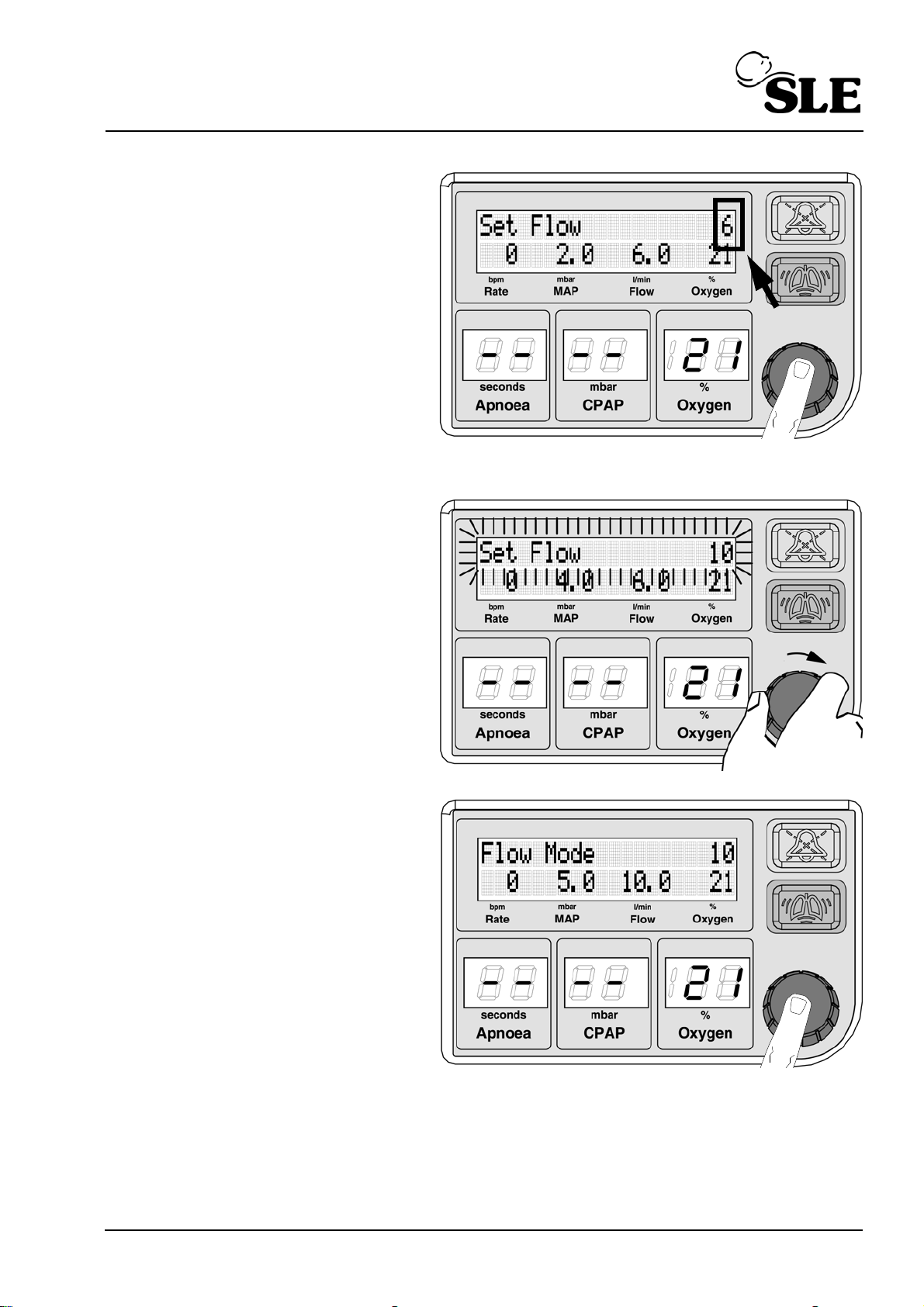
Push the knob to select. The
flow will now be displayed in
the top right hand corner of
the display
Rotate the knob to the right
to set the required flow. The
text will starts to flash.
Push the knob to confirm the
required flow.
The text will change to "Flow
mode".
Page 59 of 128
Page 60
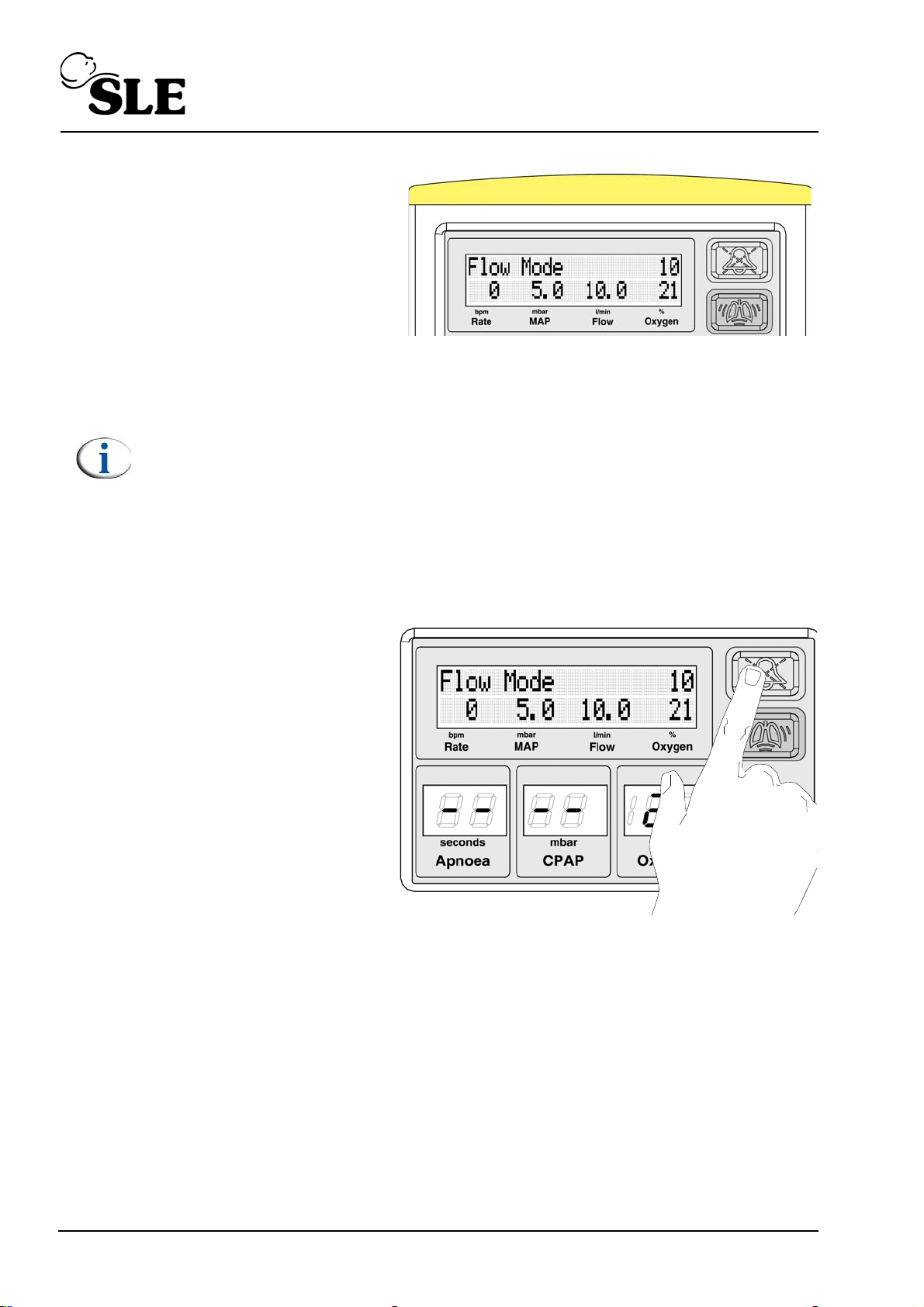
The SLE1000 will start to
deliver the set flow.
At this stage the light bar will
illuminate with a medium
priority colour. This is to
inform users that the alarm
thresholds require setting.
Note: The user should be aware that in “Flow Mode” the trigger thresholds
for the “High leak” and “Exhaust Impeded” alarms do not auto track the
MAP. The default Flow is 6LPM and the alarm thresholds are default to
2mbar (Leak) and 6 mbar (Exhaust).
When the user increases or decreases the set flow, the MAP will cross one
of the previously set thresholds, triggering the appropriate alarm. This
alarm will not clear unless the thresholds are set by the user around the
new MAP that is being used to achieve the set flow or if the MAP crosses
back to within the previously set threshold parameters.
Depress and hold the alarm
mute button for 4 seconds.
This will set the alarm
thresholds around the
measured MAP. by ± 2 mbar.
The unit indicates that the
alarms have been set by
flashing the light bar yellow
for 1 second.
Page 60 of 128
Page 61
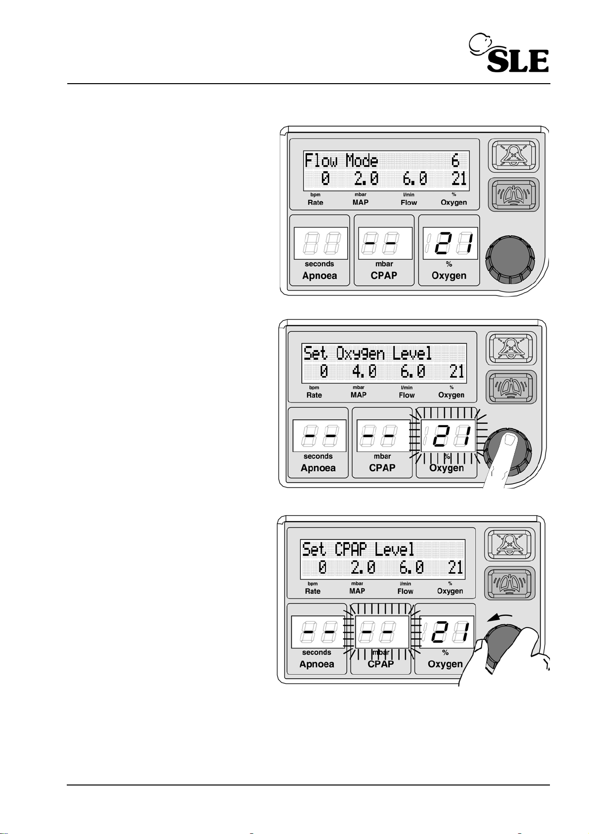
13.3 Flow mode to CPAP mode
The user is in “Flow Mode”.
Push or turn the knob.
Rotate the knob to the left
to select the “Set CPAP
level”.
Page 61 of 128
Page 62
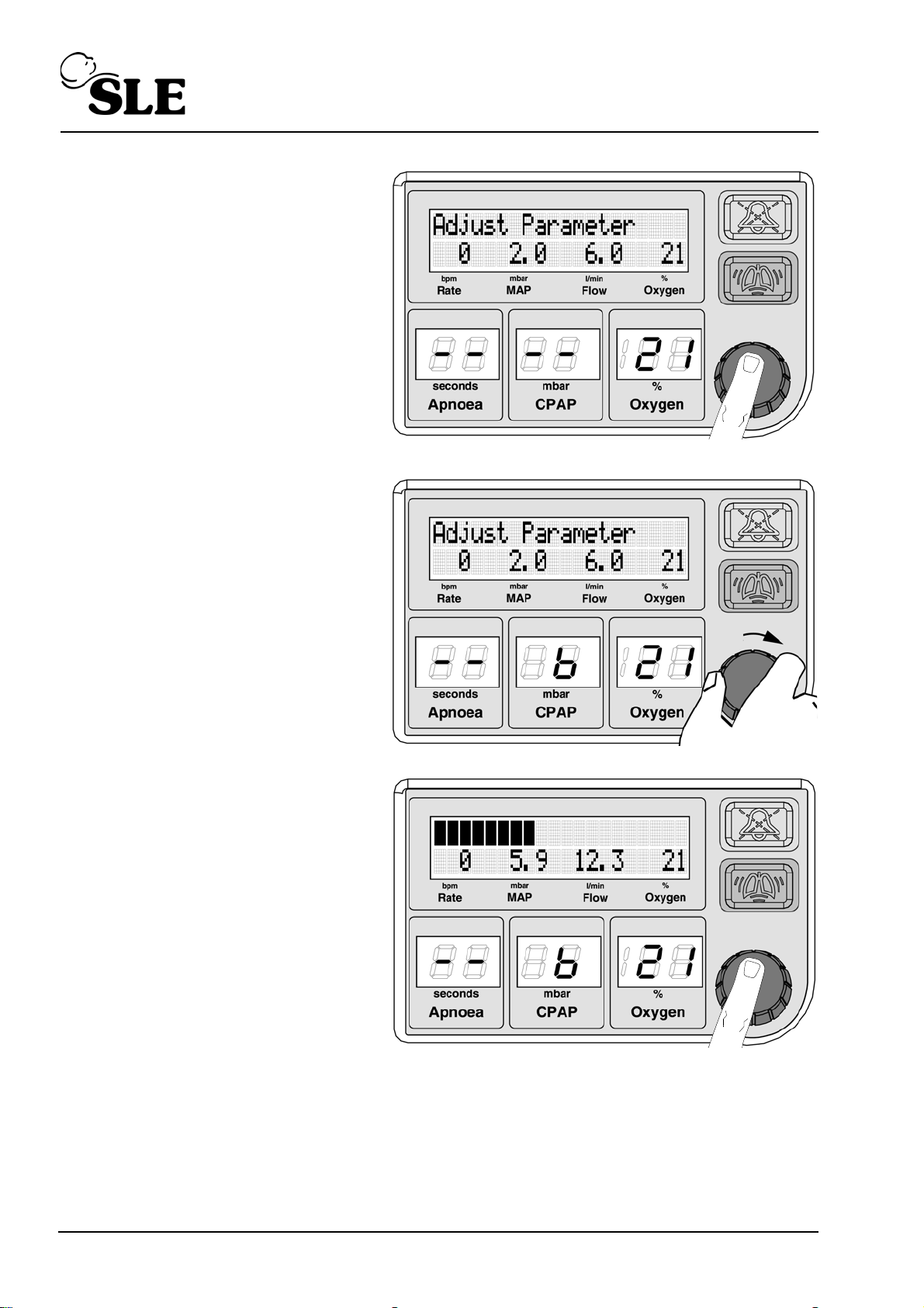
Push the knob to adjust the
CPAP parameter.
The message “Set CPAP
Level” will change to
“Adjust Parameter”.
Rotate the knob to the right
to adjust CPAP parameter.
Push the knob to confirm
the setting.
The SLE1000 will now
adjust the pressure.
The message display now
changes to the airway
pressure bargraph.
Page 62 of 128
Page 63
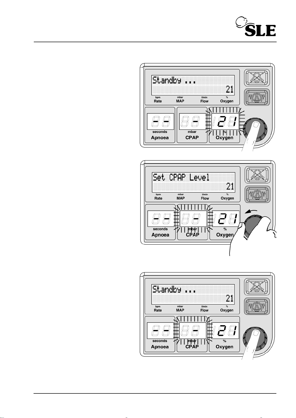
13.4 Standby to CPAP mode
Push or turn the knob.
The Oxygen parameter will
start to flash.
Rotate the knob to the left
to the CPAP parameter.
Push the knob to select the
parameter.
Page 63 of 128
Page 64
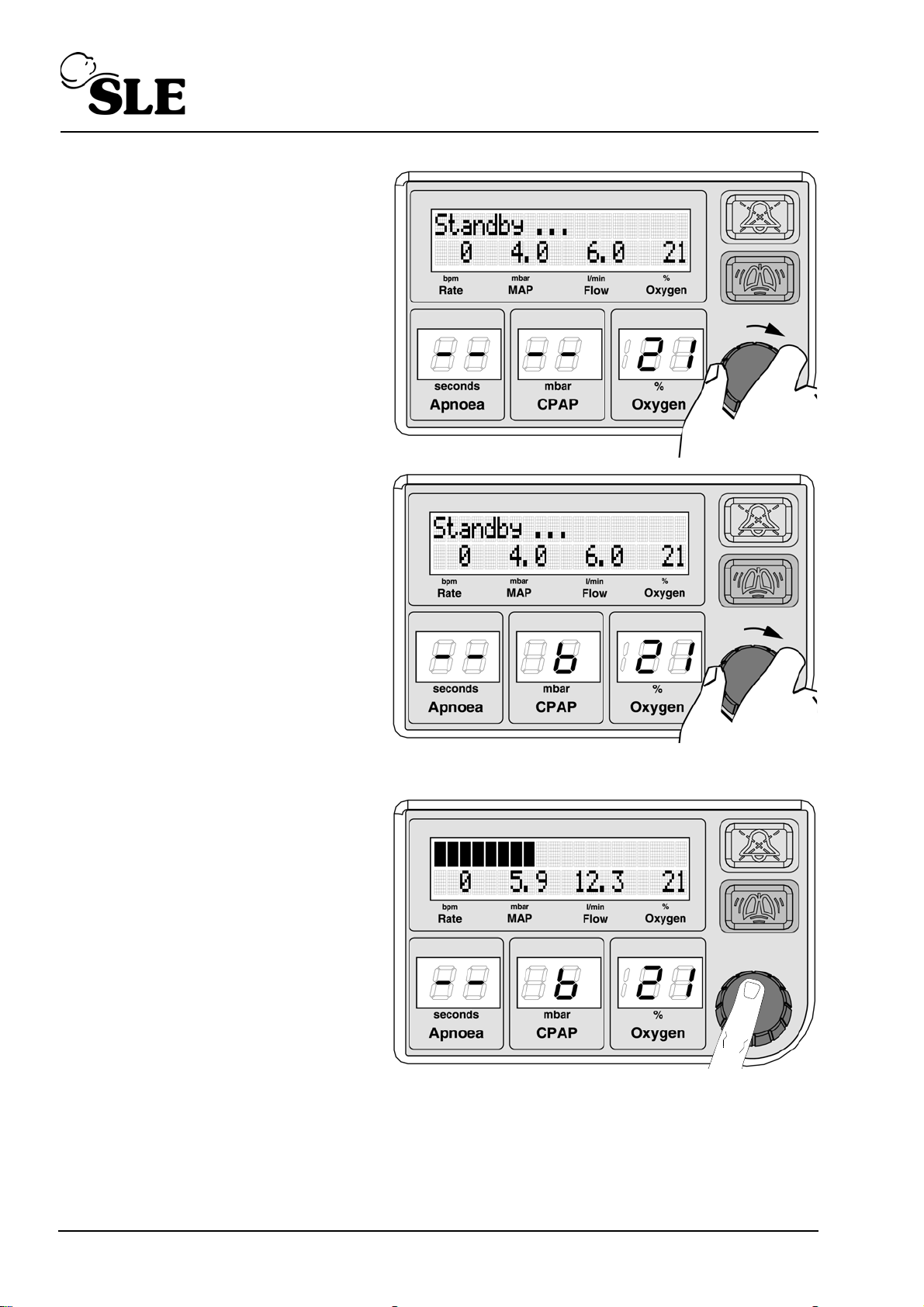
Rotate the knob to the right,
Continue past the “--”
Continuing to rotate the
knob to set the required
CPAP. The text adjust
parameter will be displayed.
Push the knob to confirm
the setting.
The SLE1000 will now
adjust the pressure.
The message display now
changes to the airway
pressure bargraph.
Page 64 of 128
Page 65
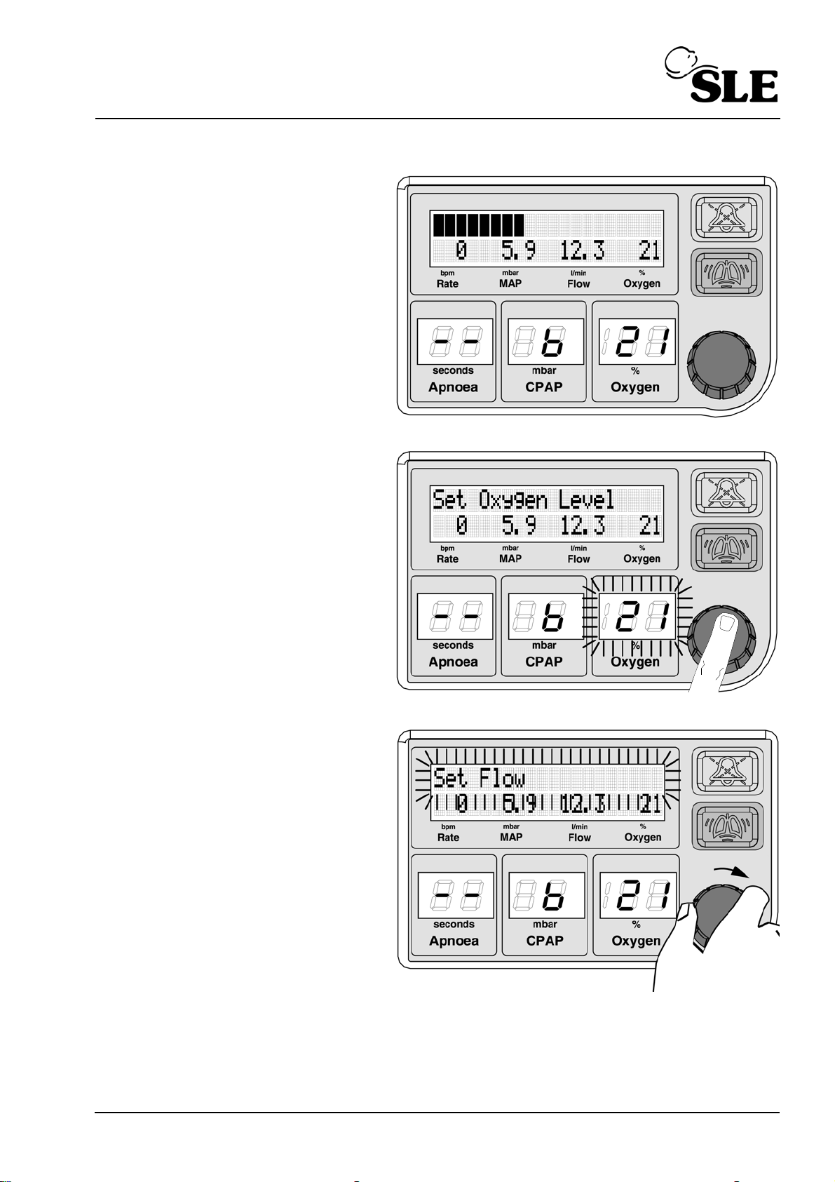
13.5 CPAP to Flow mode
The user is in CPAP mode.
Push the knob.
Rotate the knob to the right
to select "Set Flow".
Page 65 of 128
Page 66
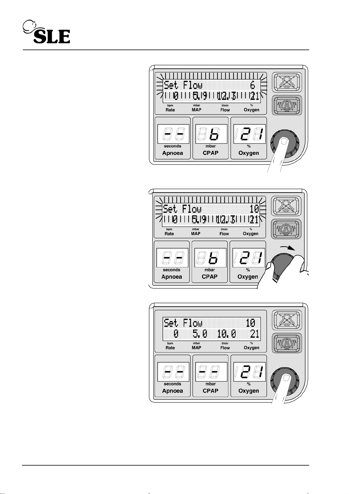
Push the knob to select.
The flow will now be
displayed in the top right
hand corner of the display
Rotate the knob to the right
to set the required flow . The
text will starts to flash.
Push the knob to confirm
the required flow.
The text will change to
"Flow mode".
Page 66 of 128
Page 67
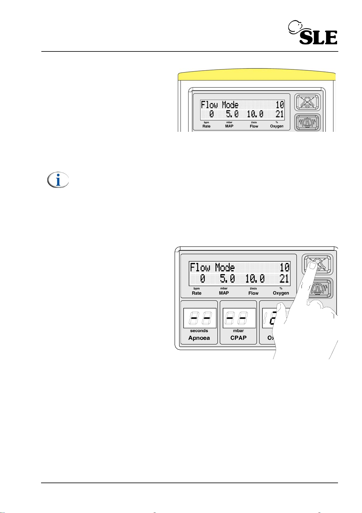
The SLE1000 will now deliver
the set flow.
At this stage the light bar will
illuminate with a medium
priority colour. This is to
inform users that the alarm
thresholds require setting.
Note: The user should be aware that in “Flow Mode” the trigger thresholds
for the “High leak” and “Exhaust Impeded” alarms do not auto track the
MAP. The default Flow is 6LPM and the alarm thresholds are default to 2
mbar (Leak) and 6 mbar (Exhaust).
When the user increases or decreases the set flow, the MAP will cross one
of the previously set thresholds, triggering the appropriate alarm. This
alarm will not clear unless the thresholds are set by the user around the
new MAP that is being used to achieve the set flow or if the MAP crosses
back to within the previously set threshold parameters.
Depress and hold the alarm
mute button for 4 seconds.
This will set the alarm
thresholds around the
measured MAP. by ± 2 mbar.
The unit indicates that the
alarms have been set by
flashing the light bar (Yellow)
for 1 second.
Page 67 of 128
Page 68

This page is intentionally blank.
Page 68 of 128
Page 69

SLE1000 Set-up
Page 69 of 128
Page 70
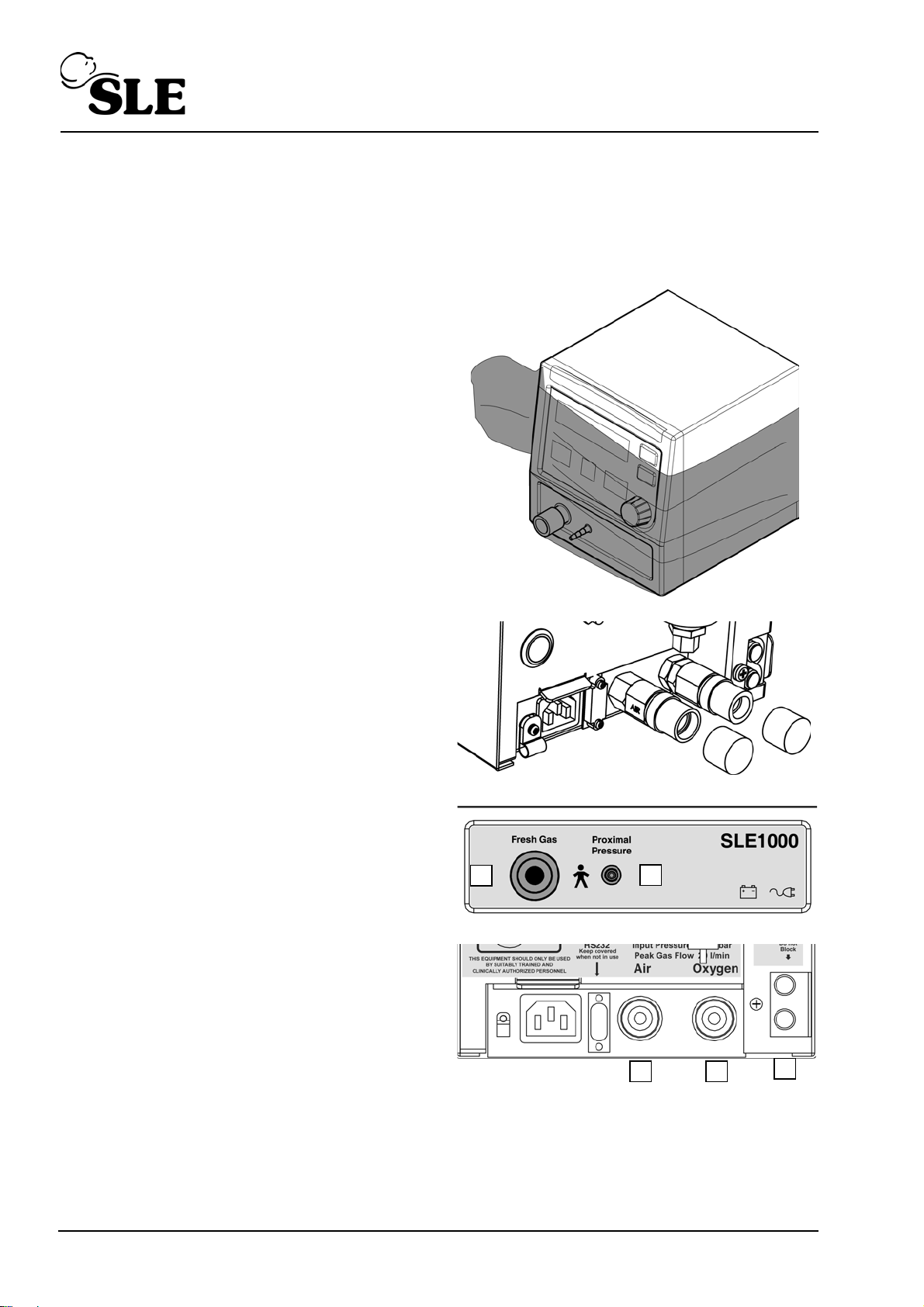
14. SLE1000 Set-up
A
B
C
D
E
14.1 First use
Setting up the SLE1000 for the first time.
Step 1. Take the SLE1000 out of
its transport carton and
remove the protective
film.
Step 2. Remove the air and
oxygen inlet port caps.
Step 3. Check that the following
ports are free from any
packing material
A. Fresh gas port
B. Proximal pressure port
C. Air inlet
D. Oxygen inlet
E. Exhaust port
Page 70 of 128
Page 71
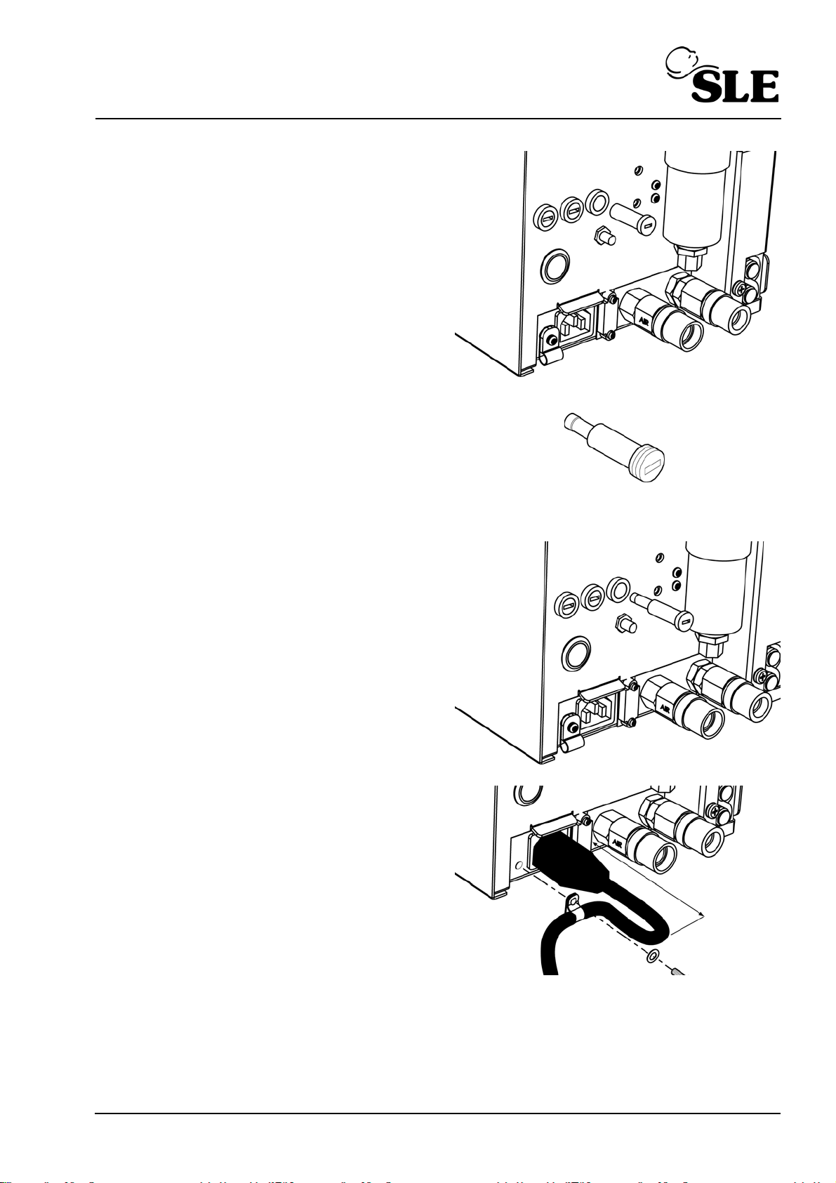
Step 4. The SLE1000 is shipped
75mm
with the main battery
disconnected.
Using a screw driver
remove the battery fuse
holder. (Indicated by
arrow)
Step 5. Insert the fuse into the
fuse holder. (T2.0A
250V). (The fuse is
located in the accessory
pack, Part nº: M0457/
2AC/001)
Step 6. Insert the fuse holder and
fuse into the receptacle.
Do not over tighten.
Step 7. Remove the screw and
washer holding the P clip.
Insert the power cable
into the socket and secure
the cable with the P clip.
Allow 75mm of cable to
form the loop.
Page 71 of 128
Page 72
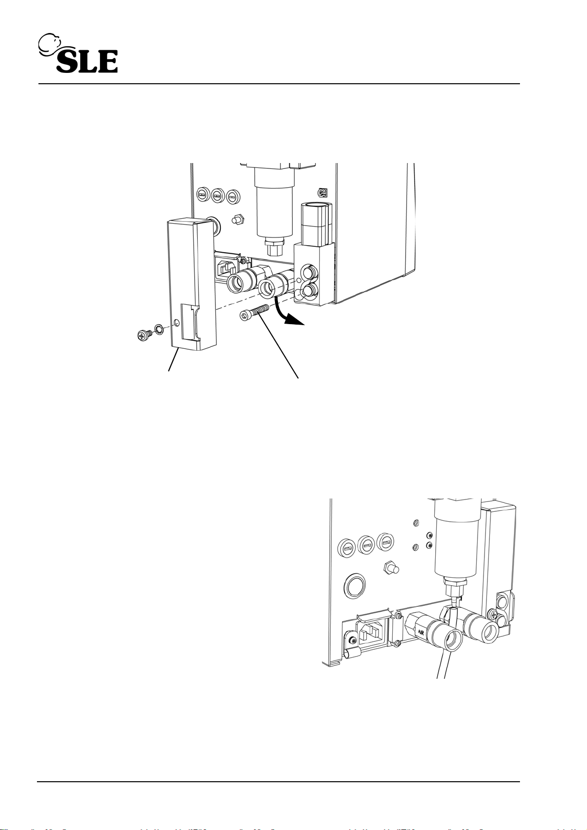
14.2 Rotation of gas inlets
Remove the locking screw to
release the air and oxygen inlets
Rotate inlets 90°
Remove the oxygen cell
cover plate
The gas inlets on the SLE1000 can be rotated through 90°. The SLE1000 is
supplied with the inlets in the horizontal position. The user can rotate the inlets
through 90° by releasing the swivel lock.
14.3 Water trap and particulate filter
Each SLE1000 unit is fitted with a water trap and particulate filter in the air side of
the pneumatic system. The water trap is auto-draining. The particulate filter will
remove particles of more than 5 micrometer (Microns) in size.
14.3.1 Setup
Prior to first use of the SLE1000 the outlet
of this water trap needs to be connected
to a drain hose and water collection cup
(Not supplied). The hose should have an
internal diameter of 4mm and be pliable
enough to fit over the hose tail bard on the
outlet of the water trap.
The other end of the hose should feed any
collected water into an open topped
collection container that can be easily
emptied.
14.3.2 Maintenace
Please refer to the SLE1000 service manual for maintenance instructions and
replacement filter instructions.
Page 72 of 128
Page 73
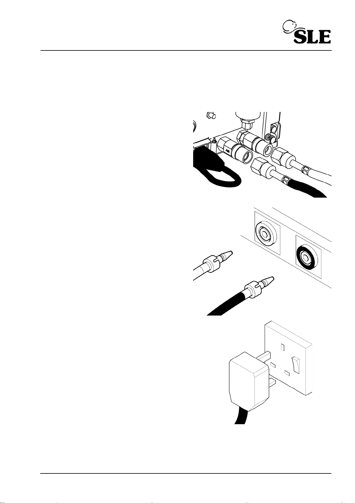
14.4 Standard setup
SLE1000 can be used with air and oxygen gas supplies or air only. For use with
air and oxygen start with section 14.4.1 on page 73 and for air only start with
section 14.4.2 on page 74.
14.4.1 With Air and Oxygen from a wall supply between 2 and 7 bar
Step 1. Connect the air and
oxygen hoses to the
SLE1000.
Step 2. Connect the air and
oxygen hoses to the wall
supplies.
Step 3. Connect SLE1000 to
mains power. Do not turn
the SLE1000 on.
Proceed to “Functional
testing prior to patient
use” on page 80.
Page 73 of 128
Page 74
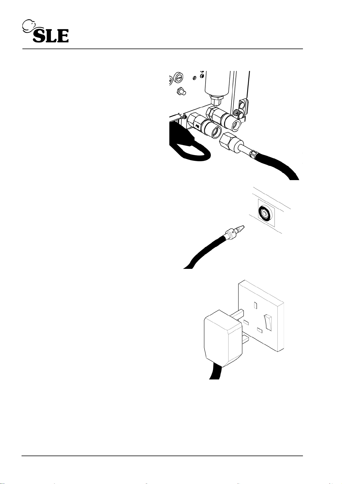
14.4.2 With air only from a wall supply between 2 and 7 bar
Step 4. Connect the air hose to
the SLE1000.
Step 5. Connect the air hose to
the wall supply.
Step 6. Connect SLE1000 to
mains power. Do not turn
the SLE1000 on.
Proceed to “Functional
testing prior to patient
use” on page 80
Page 74 of 128
Page 75
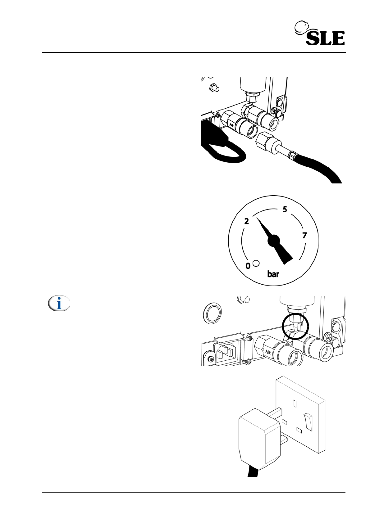
14.4.3 With air only from a medical air compressor
Step 7. Connect the air hose to
the SLE1000.
Step 8. Connect the air hose to
compressor.
Step 9. Turn on the compressor
and allow the pressure to
build up above 2 bar.
Note: The water trap / particulate
filter may bleed air due to the
auto drain mechanism not
closing. Block the outlet
momentarily to allow the
mechanism to close.
Step 10. Connect SLE1000 to
mains power. Do not turn
the SLE1000 on.
Proceed to “Functional
testing prior to patient
use” on page 80
Page 75 of 128
Page 76
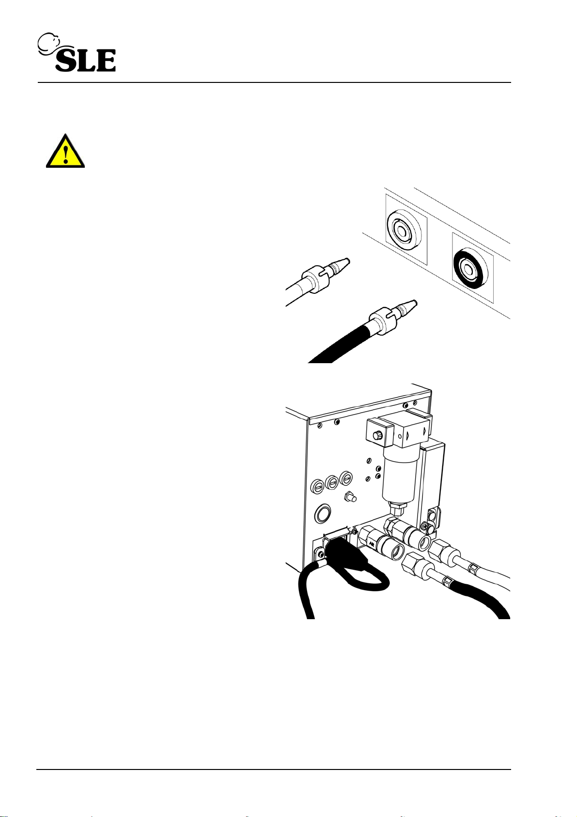
14.5 Disconnection of air and oxygen hoses
Warning: The SLE1000 does not produce any pneumatic noise when turned
off. Always disconnect the air and oxygen hoses from the wall outlets prior
to disconnection from the unit.
Step 1. Disconnect the air and
oxygen hoses to the wall
supplies.
Step 2. Disconnect the air and
oxygen hoses to the
SLE1000.
Page 76 of 128
Page 77
14.6 Battery charging
14.6.1 Prior to first use
The SLE1000 should be connected to mains power for 8 hours prior to first use to
allow the batteries to charge.
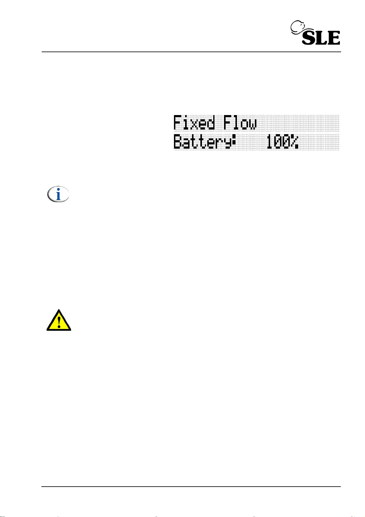
After 8 hours confirm that
the battery status indicator
reads 100%.
14.6.2 Battery charging whilst in use
The SLE1000 will charge the batteries when connected to mains.
Note: The SLE1000 does not have to be turned on for the charging to take
place.
14.7 Battery care
The SLE1000 contains 1 sealed lead acid battery that can operate the unit for
upto 4 hours in the event of a mains power fail situation. The 4 hour period stated
is for a battery that is new or for a battery that has not been allowed to remain in a
deep discharged state.
If the SLE1000 has been used on battery power and has been allowed to fully
discharge the battery , the battery can be described as being in a deep discharged
state. If the unit is stored or placed out of service without recharging the batteries,
the deep discharged state will reduce the battery life.
Warning: For a battery that has been allowed to remain in a deep
discharged state, the damage is irreversible. On re-charging a damaged
battery the service life will be curtailed.
14.8 Using the SLE1000 on battery power.
The SLE1000 is not designed to be started and used on battery power only, as it
is a mains powered device with battery backup.
If attempting to start the unit purely on battery power and the battery and mains
indicator lights are flashing whilst the power on button is depressed, the unit will
not start. Reconnect mains power and leave connected to mains for a minimum of
8 hours to fully recharge the battery.
If the unit starts on battery power and after the pneumatic and oxygen calibration
test the low battery (medium priority) alarm becomes active, restore mains power
immediately as the unit has only 10 to 20 minutes operating time left. If the low
battery (high priority) alarm is triggered the unit will shut down after 1 minute.
Page 77 of 128
Page 78

14.9 Mains isolation
To isolate the SLE1000 electrically from the mains supply,
remove the mains plug.
14.10 Extended storage and transportation
14.10.1 Storage
If the user is intending to store the driver for a period greater than 10 days and is
unable to charge the batteries during this time as recommended in the “Warnings”
on page 19, then the following procedure is recommended. (Refer the ventilator
to a qualified technician).
14.10.2 Transportation
If the user is intending to transport the driver then the battery fuse must be
removed. (Refer the ventilator to a qualified technician)
14.10.2.1 Fuse removal procedure
Step 1. Charge the batteries for 8 hours.
Step 2. Remove the battery fuse by reversing the process described in ’14.1
First use’ on page 70.
Step 3. Ensure that the fuse remains with the unit.
Step 4. Mark the unit as having the battery disconnected.
Page 78 of 128
Page 79

Functional Testing
Page 79 of 128
Page 80
15. Functional testing prior to patient use
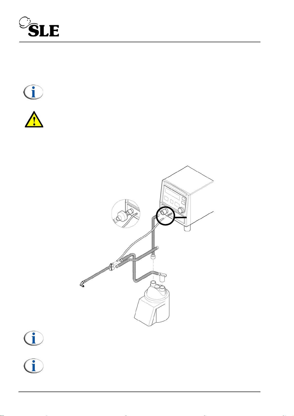
Humidifier supply line
Humidifier
Generator set
Inspiratory supply tube
Proximal airway monitoring tube
Exhaust tube
Optional bacterial filter
Connect only to circuit NOT the
SLE1000 nCPAP driver.
Do not make this
connection.
Set the driver up as per the standard setup (section 14.4 on page 73).
Set the humidifier up as per the manufacturers instructions.
Note: When functional testing requires handling of the generator / patient
circuit please ensure that cross contamination does not occur.
Warning: If any of these tests do not function as described and the problem
can not be rectified by reference to the trouble shooting chapter on
page 89, then the unit should not be used until it has been repaired. Please
contact an SLE approved engineer, or SLE.
1. Connect the delivery circuit and flow generator as per the manufacturer’s
instructions. Flow generators and delivery circuits may differ in construction
from what is shown below .
Note: DO NOT connect the proximal airway tube to the driver at this time.
Connection may cause the pneumatic test to fail. (Gas flow error).
Note: Fit a set of prongs that can be discarded after functional testing.
Page 80 of 128
Page 81
15.1 Battery test.
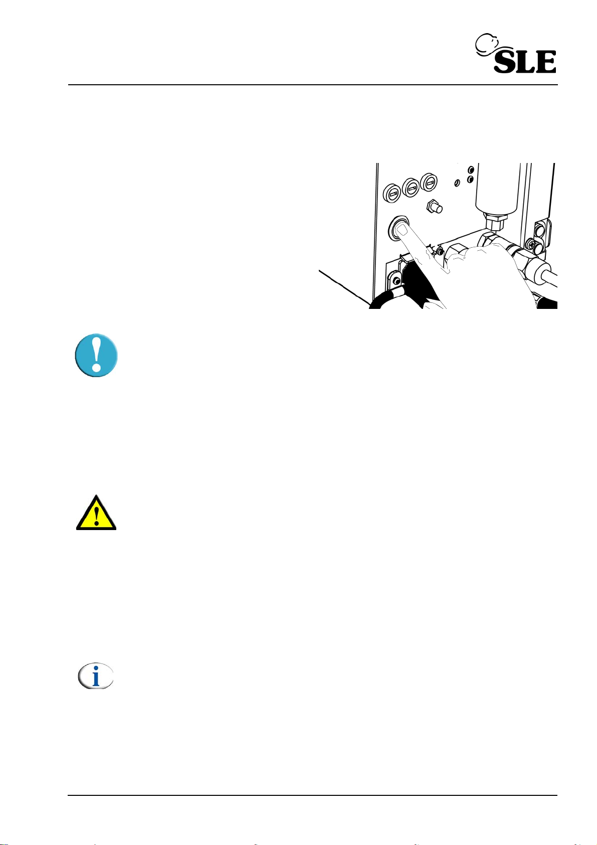
1. Disconnect the mains plug.
2. Turn on the SLE1000.
Caution: If both the battery indicator and mains icon flash when the power
button is depressed the battery is depleted. Connect mains power and allow
the unit to charge for a minimum of 8 hours. The user can use the unit, but
must be aware that the backup battery is depleted and may not be able to
support ventilation in the event of a mains power fail situation, until the
recharge cycle is complete. Check the battery status from the CPAP or flow
modes.
3. Allow the unit to perform its self test.
4. Confirm that the alarm sounder generated an alarm tone, all the LCD and
LED displays cycled through the test as described in section 7.1 on page 26.
Warning: If the user notes that on power up the unit sounder did not
produce an alarm tone, or that the LCD or LED did not function as
described, then remove the unit from service and route for repair/
investigation.
5. Re-connect mains power.
6. Wait for then unit enter “Standby mode”.
15.2 Mains disconnect alarm
7. Connect the proximal airway tube
8. Set a CPAP pressure of 5 mbar.
Note: If you are using the unit with air only, the “O2 CALIB ERROR” will be
triggered. Press the alarm mute button twice to clear the alarm message.
9. Occlude the generator outlet.
10. Remove the mains lead from the wall socket.
Page 81 of 128
Page 82

11. The SLE1000 should display and sound the “MAINS DISCONNECT” alarm.
The mains power not connected icon on the front of the driver should
Illuminate.
12. Reconnect mains power and cancel the alarm indication.
15.3 Total power fail alarm test.
13. Turn the unit off. The total power fail alarm will now sound.
14. Repress the button to cancel.
15. Disconnect the proximal airway tube.
15.4 High leak and high pressure alarm
16. Turn the unit back on.
17. Allow the pneumatic test to clear and the unit to enter standby mode.
18. Connect the proximal airway tube.
19. Wait until the oxygen system has completed its calibration.
20. Set a CPAP pressure of 5 mbar.
Note: If you are using the unit with air only, the “O2 CALIB ERROR” will be
triggered. Press the alarm button twice to clear the alarm message.
21. Remove the occlusion from the generator outlet.
22. The SLE1000 should display and sound the “HIGH LEAK” alarm after
approximately 1 minute.
23. Occlude the generator outlet and the exhaust tube.
24. The SLE1000 should display and sound the “HIGH PRESSURE” alarm, the
driver should cut the fresh gas flow.
25. Remove the occlusion from the generator outlet and exhaust tube.
26. The SLE1000 will re-instate the CPAP pressure after approximately 5
seconds.
27. The SLE1000 should display and sound the “HIGH LEAK” alarm.
28. Re-occlude the generator.
29. Wait for the alarm to clear.
30. Move directly to the Apnoea alarm test.
15.5 Apnoea alarm
31. Set the Apnoea time to 10 seconds.
32. After 10 seconds the APONEA alarm will sound and the driver will increase
the CP AP level by 3 mbar. this is indicated by “+3” being displayed in the right
hand corner of the LCD display.
33. Turn off the Apnoea alarm.
Page 82 of 128
Page 83
15.6 Zero pressure alarm and purge check
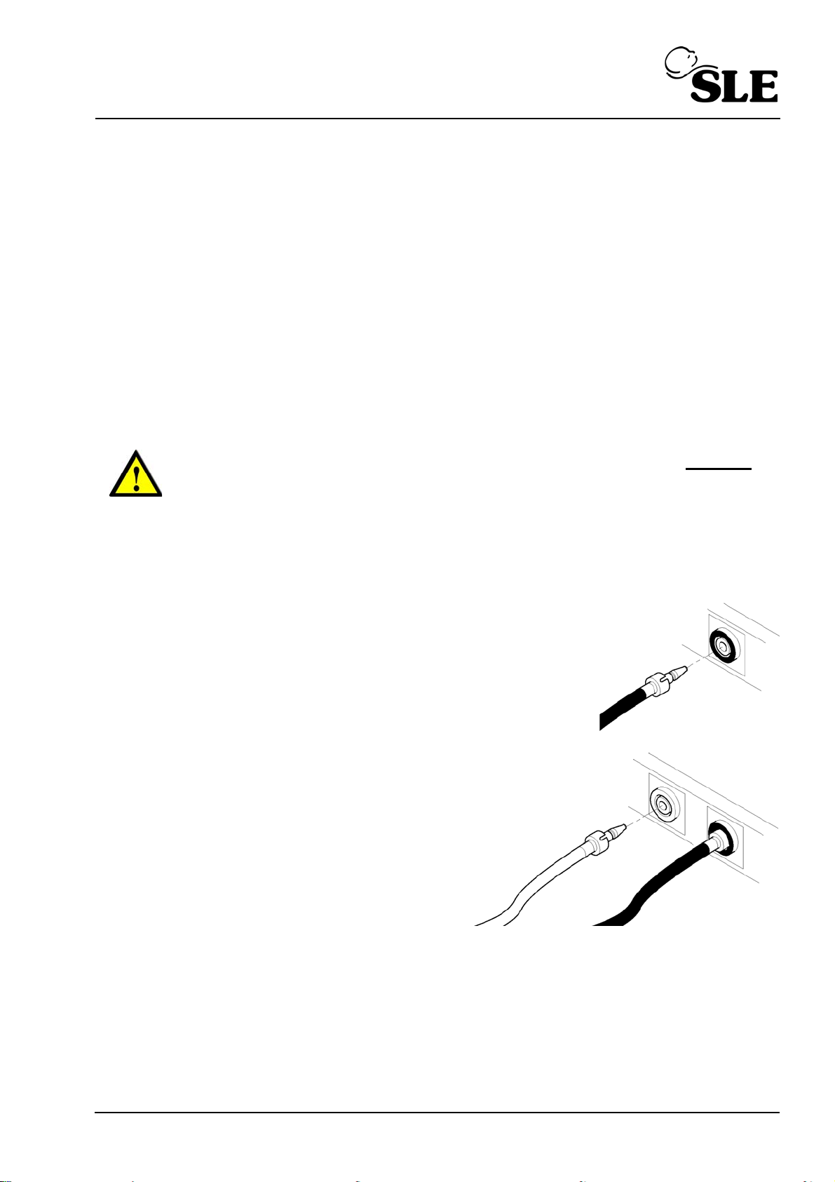
Air supply hose
O2 supply hose
34. Disconnect the proximal airway tube from the proximal pressure port.
35. The SLE1000 should display and sound the “Zero Pressure” alarm.
36. Occlude the Proximal Pressure port.
37. The SLE1000 should display and sound the “High Pressure” alarm.
38. Remove the occlusion from the port.
39. The SLE1000 should display and sound the “Zero Pressure” alarm.
40. Reconnect the proximal airway tube to the proximal pressure port.
41. Reset the alarm by pressing the alarm button twice.
15.7 Gas supply alarms
Warning: Disconnect the gas supplies from the wall outlet only. DO NOT
unscrew the hose connections from the rear of the SLE1000.
15.7.1 Procedure when using air and oxygen
1. Select fixed flow mode of 6 l/min.
2. Set the % of Oxygen to 25%
3. Disconnect the air supply from
wall outlet. The SLE1000 should
display and sound the “NO AIR
SUPPLY” alarm.
4. Reconnect air supply, cancel the
alarm.
5. Disconnect the O
supply from
2
wall outlet. The SLE1000 should
display and sound the “NO
OXYGEN SUPPLY” alarm.
6. Reconnect oxygen supply, cancel
the alarm. The unit will re-calibrate
the Oxygen.
7. Set the SLE1000 to “Standby...”
mode.
Page 83 of 128
Page 84

15.7.2 Procedure when using an air only
Air supply hose
1. Select fixed flow mode of 6 l/min.
2. Disconnect the air supply from
wall outlet. The SLE1000 should
display and sound the “NO AIR
SUPPLY” alarm.
3. Reconnect air supply, cancel the
alarm.
4. Set the SLE1000 to “Standby...”
mode.
15.7.3 Procedure when using an air compressor
1. Select a CPAP pressure of 12 mbar.
2. Turn off the compressor. The SLE1000 should display and sound the “NO AIR
SUPPLY” alarm.
Note: The user may have to wait for the pressure in the compressor
reservoir to drop, before the alarm is generated. As the pressure drops the
“Zero Pressure” alarm is generated as the pressure drops before the “No
Air Supply” alarm is generated.
3. Turn on the compressor. Occlude the watertrap outlet unit the internal valve
closes.
4. Set the SLE1000 to “Standby...” mode.
Functional testing is now complete.
Page 84 of 128
Page 85

Operational Considerations
Page 85 of 128
Page 86

16. Operational considerations
16.1 General
16.1.1 Standby mode
The patient must not be connected to the unit in “Standby” mode. The unit
does not deliver any therapeutic flow in this modes. In “Standby” mode all
patient and gas alarms are disabled with the exception of the “Low battery”
alarm and all system failure alarms.
16.2 CPAP
16.2.1 CPAP setting of 2 to 4 mbar
If the user is using the SLE1000 with small or medium prongs and a CPAP
pressure of between 2 and 4 mbar, the unit may not detect the disconnection of
the patient from the circuit.
The SLE1000 must not be used as the sole form of patient monitoring.
Independent monitoring of blood gases must be used in conjunction with
the SLE1000. Breath detection technology used in the apnoea monitor
function is based on rate and magnitude of change in the pressure
measured in the patient interface (that is shown on the bar graph). The
sensitivity of the technology has limitations with the smallest patients
(<1000g) and if a leak exists or if the patient opens/breathes by the mouth.
The apnoea monitor may be disabled if breath non-detection results in
nuisance apnoea alarms.
16.2.2 Setting pressure trigger sensitivity
When delivering CPAP with Apnoea detection turned ON the user may have to
adjust the pressure trigger sensitivity. The method of setting the pressure trigger
sensitivity is described in’9.2.1 Pressure trigger sensitivity’ on page 37. If the user
deems that the BPM rate is high due to reasons other than patient effort then they
can decrease the sensitivity by reducing the value from the default of 3 down to 1.
The user can increase the sensitivity by increasing the value from 3 to 6. Patient
trigger detection determines the delivery of backup breaths in an apnoeaic
episode.
Page 86 of 128
Page 87

Operation
Page 87 of 128
Page 88

17. Basic operation
The following chapter describes the basic operation and is not intended to be
prescriptive.
17.1 Monitoring
The recommended patient monitoring requirements are:
1. ECG/heart rate.
2. Respiration rate
3. Blood pressure (either by invasive or non invasive means).
4. Oxygen saturation.
5. Blood gas saturation by either transcutaneous carbon dioxide arterial /
capillary blood sampling.
6. Regular cranial ultrasound examinations (in the newborn).
7. Standard nursing care for Intensive Care patients.
17.2 Operation
Step 1 Setup the SLE1000 as described in section 14.4 on page 73.
Step 2 Ensure that the SLE1000 has been functionally tested as described in section 15.
on page 80.
Step 3 Ensure the unit has calibrated the oxygen system.
Note: If you are using the unit with air only, the “O2 CALIB ERROR” will be
triggered. Press the alarm button twice to clear the alarm message. The unit
will display “- -”. Do not set the % O2 above 21% as this will trigger the “NO
O2 SUPPLY” alarm.
Step 4 Set the SLE1000 into the required mode.
Step 5 Prepare the patient bonnet and select the prong or mask suitable for the patient.
Step 6 Attach the generator circuit to the patient.
Step 7 Set the Apnoea alarm time.
Step 8 Adjust the % oxygen, (If the unit is connected to air only leave the setting at 21%).
Step 9 Monitor the patient condition and adjust parameters accordingly.
Page 88 of 128
Page 89

Troubleshooting Chart
Page 89 of 128
Page 90

18. Troubleshooting chart
Symptom Possible Cause Remedy
Alarm message:
High Pressure
Alarm message:
No Air Supply
Alarm message:
No Oxygen Supply
Alarm message:
High Leak
Proximal pressure exceeds 15.5mbar.
Nasal prongs blocked
Filters occluded with water.
Exhaust tube blocked.
Air supply is too low (<2.0 bar) to
assure normal operation.
Check wall connection. Ensure air pressure is
Oxygen supply is too low (<2.0 bar) to
assure normal operation.
Check wall connection. Ensure oxygen pressure is
Unable to attain set CPAP level, and
flow has reached maximum level.
Check patient connection.
Check patient circuit.
between 2 and 7 bar.
between 2 and 7 bar.
Alarm message:
Zero Pressure
Alarm message:
Exhaust Impeded
Possibly the circuit or patient interface
has become disconnected.
Flow mode selected without alarm
thresholds being set.
MAP drops to zero
Proximal pressure tube disconnected Check patient connection.
Pressure exceeds set CP AP, and flow
has reached minimum level.
Exhaust tube blocked.
Flow mode selected without alarm
thresholds being set.
Check patient connection.
Check patient circuit.
Set alarm threshold.
Check patient circuit.
Check bacterial filter.
Check patient circuit
Set alarm threshold.
Page 90 of 128
Page 91

Symptom Possible Cause Remedy
Alarm message:
Gas Flow Error
Alarm message:
High BPM rate
Unit started with complete circuit
attached.
Water in circuit creating circuit noise.
See “High BPM rate” on page 100.
Disconnect proximal airway
line and cycle power.
Check patient circuit.
Adjust trigger sensitivity.
Page 91 of 128
Page 92

This page is intentionally blank.
Page 92 of 128
Page 93

Technical Information
Page 93 of 128
Page 94

19. Cleaning and disinfection
All cleaning, disinfection and sterilizing should be carried out under the direction of the
appropriate hospital authority.
DO NOT allow moisture to enter the electronic module or its electrical sockets. Electronic
malfunction may result.
DO NOT steam autoclave the driver or otherwise subject it to temperatures above 62°C.
DO NOT immerse any part of the driver in any liquid
19.1 Preparation of a new SLE1000 CPAP driver
Remove all transit packaging. Inspect the fresh gas port and proximal airway port for any
packing material. (Retain packaging for future use).
Remove the protective film.
Remove the inlet air and O2 gas port caps. (Retain for future use).
Allow the unit to acclimatize, i.e if the unit has been stored in a cold or humid environment
whilst in transit/storage.
Disinfect the driver as per section 19.4 on page 95.
19.2 Cleaning and disinfection of an in-service driver
Before cleaning or disinfecting the exterior of the driver the following tasks should be
performed:
• The mains cable should be disconnected from the mains supply.
• Remove the patient circuit and bacterial filters. Discard any single use items as per
appropriate hospital authority guidelines. Reusable items should be processed as
per appropriate hospital authority guidelines and the manufacturers instructions.
• Disconnect the gas supplies from the wall outlets.
• Disconnect the Oxygen and Air hoses from the driver and cap the inlet ports.
Warning (General): Do not insert any object in to the gas ports. This action
will result in damage to the port. If the user believes there is a foreign object
in a gas port, please refer the driver to qualified service personnel for
inspection and repair.
Page 94 of 128
Page 95
19.3 Cleaning Method
Note: Cleaning is an essential prerequisite to disinfection and sterilization.
For cleaning use three clean, disposable, absorbent, non-shedding cloths. Wipe clean with
the first cloth using a hand hot water/mild general purpose detergent solution (as prescribed
by the appropriate hospital authority). Do not overload the cloth with liquid. Remove the
water/mild general purpose detergent solution with the second cloth using water only . Do not
overload the cloth with liquid. Wipe dry with the remaining cloth. Care should be taken to
ensure that the driver gas ports are not blocked by any debris.
Warning: Ensure that the detergent solution does not enter the unit (LCD and
LED windows). Do not use any abrasive cleaners these surfaces.
19.4 Disinfection method
Note: Alcohols such as 70% isopropanol have a good activity against
bacteria and viruses. They should only be used after all visible surface dirt
has been removed from the area to be disinfected.
For disinfection use two clean, disposable, absorbent, non-shedding cloths. Wipe clean with
the first cloth using Alcohol (70% isopropanol). Wipe dry with the remaining cloth.
Warning: Disinfectants containing compounds similar to PHENOL or
ALKYLAMINES (Glucorrotamine) are unsuitable.
Page 95 of 128
Page 96

20. Messages & alarms
20.1 Messages
The user interface messages displayed on 20 character wide LCD.
User message Description Action
Airway pressure
bar graph (nonscaled)
Audio Paused Indicates that user has activated the
Adjust Parameter Second stage of user interacting with
Indicates normal (technical and
patient) operation. Tolerable
underlying conditions have been
acknowledged by the user.
alarm cancel or alarm ‘pre-mute’.
If alarm button is pressed while the
‘Alarm Paused’ message is displayed,
then normal ‘un-paused’ mode is
immediately resumed.
device, where the parameter is
adjusted.
None
Resets any current alarm
condition.
Pauses alarm audio for 120
seconds or until button or is
pressed again.
Turning the dial will
increment/decrement the
parameter in focus.
Pressing the dial will confirm
selection. Times out and
reverts to original value after
3 sec of inaction.
Battery N% Display of the battery charge level in
percent
Flow Mode Displayed to indicate that the user is
in flow mode
Pneumatic test Displayed during internal test Clear only when test has
Set Apnoea Time
Set CPAP Level
Page 96 of 128
Indicator that the Apnea Time can be
selected.
Indicator that the CPAP Level can be
selected.
Clears itself after 10 sec.
Present whilst delivering the
prescribed flow.
passed.
Clears itself after 5 sec.
If selected clears after 10
sec.
Clears itself after 5 sec.
If selected clears after 10
sec.
Page 97

User message Description Action
Set Flow
Indicator that the flow can be
selected.
Set Oxygen Level
Indicator that the Oxygen Level can
be selected.
Show Batt. level
Indicator that the Battery Level can be
selected.
Show Alarm Hist. Indicator that the Alarm History can be
selected.
Set Trigger Sen. Indicator that the Trigger Sensitivity
can be selected.
Start O2 Calib Indicator that the O2 calibartion
routine can be selected.
Clears itself after 5 sec.
If selected clears after 10
sec.
Clears itself after 5 sec.
If selected clears after 10
sec.
Clears itself after 5 sec.
If selected clears after 10
sec.
Clears itself after 5 sec.
If selected clears after 10
sec.
Clears itself after 5 sec.
If selected clears after 10
sec.
Clears itself after 5 sec.
If selected clears after 10
sec.
Been used for: Display of the battery charge level in
percent
SLE1000 Ver. N.N Version display during power-on-self-
test.
Ready... Indicates that power-on-self-test has
completed.
<no message> Indicates that a particular history log
location does not have any stored
event (i.e. alarm has not occurred)
The user has to press the
alarm mute button to cancel
display.
Clears itself on completion
of the power-on-self-test.
Clears itself after 2 sec.
None
Page 97 of 128
Page 98

20.2 Alarm messages and sounds.
20.2.1 Alarm messages.
Alarm messages ranked in order of priority. The current message of highest priority ranking
is stored in the history log. Simultaneous lower ranking messages are often the
consequence of a higher priority, and they are not stored in the history log. The term ‘alarm’,
when used in the Action column, means sounding and displaying a conforming audio-visual
alarm.
20.2.1.1 Latching and non latching alarms
A latching alarm is an alarm message that once generated will continue to display both the
audible and visual elements even though the original alarm condition has cleared.
A non latching alarm is an alarm message that will display both the audible and visual
elements only during the alarm condition. If the alarm condition clears the audible and visual
elements self cancel.
Alarm message Description Action
Simultaneous ‘Battery
Error’ and ‘Mains
disconnect’
(blank display)
Total power loss. Battery has
emptied or battery fuse has failed,
while in battery operating mode.
The 1 to 2 l/min bypass air flow will
cease once the volume chamber is
empty.
Priority: HIGH
Type: TECHNICAL
Device appears as switched
off. Normal alarm system
and history log is
inoperable.
Power manager sounds
backup sounder
continuously, while backup
capacitor power exists
(approx 10 minutes), or until
user presses power ONOFF button.
Calib Faulty Calibration integrity error
Latching HIGH priority alarm.
Cannot be disabled.
Priority: HIGH
Type: TECHNICAL
Page 98 of 128
Remove the unit from
service.
Remove patient to an
alternative form of
ventilation. Remove the unit
from service.
Page 99

Alarm message Description Action
System Failure N
System Failure
Single or multiple subsystem failures.
N = system failure
number which can be
between 1-255.
Latching HIGH priority alarm.
Cannot be disabled.
Priority: HIGH
Remove patient to an
alternative form of
ventilation. Remove the unit
from service.
Type: TECHNICAL
Gas Flow Error Start up self test has detected
abnormal pneumatic system
response, or lacking gas supply.
Latching HIGH priority alarm.
Priority: HIGH
Type: TECHNICAL
High Pressure Proximal pressure exceeds 15.5
mbar.
Non-latching HIGH priority alarm.
Priority: HIGH
Type: TECHNICAL
Self test is repeated and
clears itself upon successful
result.
If ventilating - remove
patient to an alternative
form of ventilation. Remove
the unit from service.
Cuts fresh gas flow and
evacuates pressure from
the circuit. 1.5 l/min bypass
flow is delivered, to flush
CO2 build up. Device will
restart after 5 seconds.
Check Patient, check
patient circuit. Adjust
ventilation parameters.
If alarm repeats after the
above checks remove
patient to an alternative
form of ventilation. Remove
the unit from service.
Apnoea Breath not detected within the user
set apnoea period.
Non-latching HIGH priority alarm.
Is reset by a patient breath.
Priority: HIGH
Ty pe: PATIENT
Triggers a stimulation
breath of 3 mbar above set
CPAP for 0.3 seconds (only
pressure mode).
User has option for
disabling the apnoea
monitoring function (value
shows ‘--’).
Check Patient, check
patient circuit. Adjust
ventilation parameters.
Page 99 of 128
Page 100

Alarm message Description Action
No Air Supply Air supply is too low (<2.0 bar) to
assure normal operation.
Device will deliver 100%
oxygen as set flow.
Connect air supply. If
Non-latching HIGH priority alarm.
Suspends high oxygen alarm.
ventilating - remove patient
to an alternative form of
ventilation. Remove the unit
Priority: HIGH
from service.
Type: TECHNICAL
No Oxygen Supply Oxygen supply is too low (<2.0 bar)
to assure normal operation. Only
active if FiO
is set >21%.
2
Non-latching HIGH priority alarm.
Suspends low oxygen alarm.
Priority: HIGH
Type: TECHNICAL
High BPM rate The measured breath rate exceeds
90 BPM for at least 6 seconds
when the Apnoea is set in the
range of 5 and 90 seconds.
Device continues to deliver
air only gas to patient.
User can prevent
recurrence by setting FiO
2
to 21%.
Connect oxygen supply.
If no oxygen present, set
the unit to run on air only by
canceling the alarm
message.
If ventilating - remove
patient to an alternative
form of ventilation. Remove
the unit from service.
Check Patient, check
patient circuit. Adjust
Apnoea parameters.
Page 100 of 128
Disabled if Apnoea is OFF (--)
High rate could indicate false
breath detection due to pressure
signal noise (e.g. from water in
breathing circuit). False detection
risk masking an apnoea condition.
Non-latching HIGH priority alarm.
Priority: HIGH
 Loading...