

Page 1
Page 2

Software/Manual application Information:
Note: This manual is to be used only with model A ventilators using the following
software version:
Version 3, 3.1, 3.2, 3.3, 4 & 4.1
Contact Information:
SLE Limited
Twin Bridges Business Park
232 Selsdon Road
South Croydon
Surrey CR2 6PL
Telephone: +44 (0)20 8681 1414
Fax: +44 (0)20 8649 8570
E-mail: [email protected]
Web site: www.sle.co.uk
(E-mail’s should be addressed to the Service Manager)
All rights reserved. No part of this publication may be reproduced, stored in any retrieval system, or transmitted
in any form or by any means, electronic, mechanical, photocopy, recording or otherwise, without prior
permission of SLE. © Copyright SLE 12/04/2007.
Manual : SM0015 Issue 10
SLE Part Nº: N6645
Page 2 (Model A)
Page 3

Contents
1. Warnings and Cautions ............................................................................................. 10
1.1. Warnings ........................................................................................................ 10
1.2. Cautions ......................................................................................................... 11
2. Principles of Operation .............................................................................................. 14
2.1. Electronic System........................................................................................... 14
2.2. Pneumatic System ......................................................................................... 15
3. Description of Symbols ............................................................................................. 18
4. Equipment list ........................................................................................................... 22
5. ENGMODE ............................................................................................................... 24
5.1. Accessing the Calibration Programs .............................................................. 24
5.2. Ventilator Calibration Program ....................................................................... 26
5.3. O2 & Flow System Calibration........................................................................ 28
5.4. Reset Elapsed Time ....................................................................................... 29
5.5. Exit ................................................................................................................. 29
5.6. Touch Screen Calibration Program ................................................................ 29
6. Component Replacement Procedure ........................................................................ 32
7. Preparing the SLE5000 ............................................................................................. 33
8. Component Replacement (Electronic unit) ............................................................... 35
8.1. N6634 CAN Card ........................................................................................... 35
8.2. BIOS battery................................................................................................... 35
8.3. Disk-on-Chip................................................................................................... 36
8.4. N6631/01 PC Board ....................................................................................... 37
8.5. N6631/06 Serial controller (Touch screen)..................................................... 38
8.6. A0763/02 Control and Monitor Board............................................................. 39
8.7. M0900 Power Supply Unit.............................................................................. 41
8.8. M0901 Batteries ............................................................................................. 42
8.9. A0761 Transducer PCB Assembly................................................................. 43
8.10. Inverter PCB................................................................................................. 44
8.11. N6631/02 LCD & N6631/05 Touch Screen .................................................. 47
9. Component Replacement (Pneumatic unit) .............................................................. 56
9.1. N2185/05 & 06 Duckbill and conical filters. .................................................... 56
9.2. L0287 Blender Assembly ............................................................................... 57
9.3. N2195/06 Fresh Gas Supply solenoid (SV7).................................................. 58
9.4. N6612 Purge Regulator (PR7) Pre PAM (Proximal Airway Modification)....... 59
9.5. N6612 Purge Regulator (PR7) Post PAM (Proximal Airway Modification) ..... 59
9.6. N6614 Speed controller (FR1)........................................................................ 60
9.7. N6613 Purge Regulator (PR5) Pre Proximal Airway Modification.................. 61
9.8. N6613 or /03 Purge Regulator (PR5) Post Proximal Airway Modification ...... 63
9.9. N6615/01 Input Air Regulator (PR1)............................................................... 65
9.10. N6615/02 Input Oxygen Regulator (PR2)..................................................... 67
9.11. N6624 High Speed Jet Valves (SV9/10/11/12) ............................................ 68
(Model A) Page 3
Page 4

9.12. N6623, N6623/33 or N6623/S38 Pressure regulators (PR6) ........................69
9.13. N6623, N6623/33 or N6623/S38 Pressure regulators (PR3 &PR4) .............71
10. A0763/02 Monitor and control board .......................................................................74
10.1. U23 and U33 socket configurations for A0760 Rev D base PCB. ................74
10.2. A0763/02 board progammable devices ........................................................75
10.3. A0763/02 Board Hardware Identifier.............................................................76
11. Electrical Safety Testing of the SLE5000 ................................................................79
12. PSU Testing. ...........................................................................................................83
13. Maintenance and Overhaul .....................................................................................86
13.1. Preventative Maintenance ............................................................................86
13.2. 6, 18, 30 & 42 month preventative maintenance procedure .........................88
13.3. 12 and 36 month preventative maintenance procedure................................94
13.4. 24 month and 48 month overhaul procedures ..............................................98
13.5. 24 month / 10,000 hour overhaul procedure.................................................100
13.6. 48 month / 20,000 hour overhaul procedure.................................................108
13.7. 48 month overhaul procedure using N9010/48 overhaul kit. ........................110
14. Calibration Procedure for V3, V3.1 & 3.2 software ..................................................128
14.1. Preliminary Inspection before calibration ......................................................128
14.2. Pneumatic set up ..........................................................................................129
14.3. Calibration of Controller and Monitor subsystems ........................................130
14.4. Controller “Block and Leak” pressure sensor calibration ..............................132
14.5. Controller Blender Pressure Sensor zeroing and Input pressure reg. trim ...133
14.6. Mean Jet Pressure Regulator Calibration .....................................................134
14.7. Forward Jet Pressure Regulator Calibration.................................................135
14.8. Wave shaping for leading and trailing edge of insp. phase ..........................137
14.9. Reverse Jet Pressure Regulator Calibration.................................................138
14.10. O2 System Calibration ................................................................................139
14.11. Flow System Calibration .............................................................................139
14.12. Pressure Triggering Verification..................................................................139
14.13. Gas Fail Detection Verification....................................................................139
14.14. Blender and Oxygen Monitoring Verification...............................................140
14.15. Soak Test....................................................................................................141
14.16. Battery Charge Verification .........................................................................142
14.17. Battery Life Verification ...............................................................................142
14.18. Total Power Fail Alarm Test........................................................................142
14.19. Pressure Calibration Verification.................................................................143
15. Calibration Procedure for V3.3 software .................................................................146
15.1. Preliminary Inspection before calibration ......................................................146
15.2. Pneumatic set up ..........................................................................................147
15.3. Calibration of Controller and Monitor subsystems ........................................148
15.4. Controller “Block and Leak” pressure sensor calibration ..............................150
15.5. Controller Blender Pressure Sensor zeroing and Input pressure reg. trim ...151
15.6. Mean Jet Pressure Regulator Calibration .....................................................152
15.7. Forward Jet Pressure Regulator Calibration.................................................153
Page 4 (Model A)
Page 5

15.8. Reverse Jet Pressure Regulator Calibration ................................................ 155
15.9. Time Constant for pressure measurement waveform .................................. 156
15.10. Wave shaping for leading and trailing edge of insp. phase ........................ 156
15.11. O2 System Calibration................................................................................ 157
15.12. Flow System Calibration............................................................................. 157
15.13. Pressure Triggering Verification ................................................................. 157
15.14. Gas Fail Detection Verification ................................................................... 158
15.15. Blender and Oxygen Monitoring Verification .............................................. 159
15.16. Soak Test ................................................................................................... 160
15.17. Battery Charge Verification......................................................................... 161
15.18. Battery Life Verification .............................................................................. 161
15.19. Total Power Fail Alarm Test ....................................................................... 161
15.20. Pressure Calibration Verification ................................................................ 162
16. Calibration Procedure for V4 & 4.1 software ........................................................... 164
16.1. Preliminary Inspection before calibration...................................................... 164
16.2. Pneumatic set up.......................................................................................... 165
16.3. Calibration of Controller and Monitor subsystems........................................ 166
16.4. Controller “Block and Leak” pressure sensor calibration.............................. 168
16.5. Controller Blender Pressure Sensor zeroing and Input pressure reg. trim... 169
16.6. Mean Jet Pressure Regulator Calibration..................................................... 170
16.7. Forward Jet Pressure Regulator Calibration ................................................ 171
16.8. Reverse Jet Pressure Regulator Calibration ................................................ 173
16.9. Time Constant for pressure measurement waveform .................................. 174
16.10. Wave shaping for leading and trailing edge of insp. phase ........................ 174
16.11. O2 System Calibration................................................................................ 175
16.12. Flow System Calibration............................................................................. 175
16.13. Pressure Triggering Verification ................................................................. 175
16.14. Gas Fail Detection Verification ................................................................... 176
16.15. Blender and Oxygen Monitoring Verification .............................................. 177
16.16. Soak Test ................................................................................................... 178
16.17. Battery Charge Verification......................................................................... 179
16.18. Battery Life Verification .............................................................................. 179
16.19. Total Power Fail Alarm Test ....................................................................... 179
16.20. Pressure Calibration Verification ................................................................ 180
17. Functional Testing ................................................................................................... 182
17.1. Ventilator setup ............................................................................................182
18. Trouble Shooting Chart ........................................................................................... 216
19. Software Version History ........................................................................................ 226
19.1. SLE4000 Software ....................................................................................... 226
19.2. SLE5000 Software ....................................................................................... 227
20. Oxygen Calibration Routines .................................................................................. 230
20.1. One point or 100% Oxygen system calibration ............................................ 230
20.2. Two point or 21% & 100% Oxygen system calibration................................. 230
(Model A) Page 5
Page 6

21. Alarms .....................................................................................................................232
21.1. Alarm Protocols.............................................................................................232
21.2. Alarm Sounds ...............................................................................................232
21.3. Alarm Descriptions and actions to be taken..................................................233
21.4. Software and System Fail Protocols .............................................................252
22. Cleaning, disinfection and sterilization ....................................................................253
22.1. Preparation of a new ventilator .....................................................................253
22.2. Cleaning and disinfection of an in-service ventilator.....................................253
22.3. Cleaning method...........................................................................................254
22.4. Disinfection method ......................................................................................255
22.5. Sterilization method ......................................................................................256
23. Technical Specification ............................................................................................257
23.1. Operating Modes Conventional Ventilation...................................................257
23.2. HFO Ventilation.............................................................................................258
23.3. Measurement ................................................................................................263
23.4. Alarms...........................................................................................................265
23.5. Patient circuits...............................................................................................266
23.6. Outputs .........................................................................................................267
23.7. Gas supplies .................................................................................................268
23.8. Power, Dimensions, Standards etc...............................................................269
23.9. Environmental Storage Conditions ...............................................................269
24. Pneumatic Unit Schematic ......................................................................................270
25. Ventilator labelling ...................................................................................................271
25.1. SLE4000 .......................................................................................................271
25.2. SLE5000 .......................................................................................................272
26. Illustrated Parts List .................................................................................................274
Ventilator assembly ...............................................................................................276
Base plate and side door assembly ......................................................................284
Front facia assembly .............................................................................................286
Electronic module .................................................................................................288
Pneumatic module (Pre proximal airway modification) ..........................................321
Pneumatic module ................................................................................................327
HFO module (Pre proximal airway modification) ...................................................334
HFO module ..........................................................................................................344
Oxygen regulator module ......................................................................................357
Partition assembly .................................................................................................360
Pneumatic module, sub assembly ........................................................................364
27. Equipotential stud modification ................................................................................374
27.1. Equipotential stud connection .......................................................................375
28. Electrical Block Diagram .........................................................................................378
Page 6 (Model A)
Page 7

29. Pneumatic Unit Schematic ...................................................................................... 379
29.1. Schematic Pre PAM (Proximal Airway Modification) .................................... 379
29.2. Schematic Post PAM.................................................................................... 380
30. Pneumatic Unit Tubing connections ....................................................................... 381
30.1. Tubing Connections Pre PAM ...................................................................... 381
30.2. Tubing Connections Post PAM..................................................................... 382
31. Main Loom Circuit Diagram .................................................................................... 383
32. A0761 circuit diagram ............................................................................................. 386
32.1. Transducer PCB Assembly .......................................................................... 386
33. A0763/02 circuit diagrams ...................................................................................... 388
33.1. Micro Controller ............................................................................................ 388
33.2. Conventional Valve Drive ............................................................................. 389
33.3. Power Distribution And Hardware Identifier.................................................. 390
33.4. Analogue Valve Drive / Non Volatile Memory / Interboard Comms.............. 391
33.5. High Speed Valve Drive ............................................................................... 392
33.6. Analogue Data aquisition/Monitor port ......................................................... 393
33.7. Control & Monitor, PCB PSU Circuit............................................................. 394
33.8. Control & Monitor, Micro Non-isolated.......................................................... 395
33.9. Control & Monitor, Micro Isolated ................................................................. 396
33.10. Control & Monitor, Analog Isolated............................................................. 397
33.11. Control & Monitor, Alarm Controller............................................................ 398
Appendix 1. Calibration Checklist ................................................................................. 401
Appendix 2. Check list .................................................................................................. 409
Appendix 3. RS232 ....................................................................................................... 414
33.12. Warnings for RS232 ................................................................................... 414
33.13. Location of RS232 Port .............................................................................. 414
33.14. Overview .................................................................................................... 415
33.15. Data and Pinout description. ...................................................................... 415
33.16. Cable .......................................................................................................... 415
33.17. Parameter Descriptions and format............................................................ 416
33.18. List of parameters....................................................................................... 416
33.19. Table of current alarm condition codes. ..................................................... 419
33.20. RS232 Connection Settings and Testing Data Output ............................... 421
33.21. Glossary ..................................................................................................... 421
Appendix 4. VueLink Technical Data ............................................................................ 424
33.22. Glossary ..................................................................................................... 424
33.23. Connecting the SLE5000 to the VueLink patient monitor........................... 424
33.24. Parameter Descriptions.............................................................................. 425
33.25. Data transferred to the VueLink system from the SLE5000 ....................... 426
33.26. Alarm and inoperative indications............................................................... 428
(Model A) Page 7
Page 8

34. VueLink Task Window Layout .................................................................................431
34.1. Notes on General System Behaviour............................................................432
35. Activation of VueLink ...............................................................................................433
35.1. Disabling VueLink. ........................................................................................434
Page 8 (Model A)
Page 9
Warnings and Cautions
(Model A) Page 9
Page 10
1. Warnings and Cautions
1.1 Warnings
1. The electronic and pneumatic units of the SLE5000 infant ventilator are sealed at the
factory with two Warranty Void If Label Broken seals. If the ventilator is subject to a
warranty agreement do not attempt to carry out any procedure that would involve
breaking these seals. If you make a warranty claim and these seals are broken SLE
may deem the warranty claim null and void. If the ventilator develops a fault within the
warranty period please refer to your warranty documentation.
2. Oxygen - Fire Hazard. Oxygen vigorously supports combustion and its use requires
special precaution to avoid fire hazards. Keep all sources of ignition away when oxygen
is in use. Do not use oil or grease on oxygen fittings or where oxygen is used.
3. Check the condition of the gas supply hoses to the ventilator. Do not use any hose that
shows signs of cracking, abrasion, kinking, splits, excessive wear or ageing. Make sure
that the Air or O2 hose has not come into contact with oil or grease.
4. The SLE5000 ventilator contains temperature dependant devices which perform
normally in controlled environments in hospitals. However if the ventilator has been
stored at a temperature different to that in which it will be used, allow the unit to
acclimatize before powering up.
5. Failure to comply with the recommended service programs could lead to injury of the
patient, operator or damage to the ventilator. It is the owners responsibility to ensure
that the equipment is regularly maintained.
6. The SLE5000 contains static sensitive electrical devices. Anti static precuations must be
observed at all time when working on the ventilator.
Page 10 (Model A)
Page 11
1.2 Cautions
1. When working on the pnuematic unit, protect the front facia panel by resting it on a soft
pad.
2. Do not use a sharp instrument, such as a pen to activate the controls as the excessive
pressure applied by the point will damage the touch screen membrane.
3. The Ventilator must be connected to a suitably rated and grounded electrical power
source.
4. If the SLE5000 is adversely affected by equipment emitting electromagnetic interference
then that equipment should be switched off or removed from the vicinity of the SLE5000.
Conversely, if the SLE5000 is the source of interference to other neighbouring
equipment, it should be switched off or taken to another location.
5. The functioning of this machine may be adversely affected by the operation of
equipment such as high frequency surgical (diathermy) equipment, defibrillators, mobile
phones or short-wave therapy equipment in the vicinity.
7. The equipment is not suitable for use with, or in the presence of flammable anaesthetic
mixtures.
6. The SLE5000 flow monitoring system is calibrated to work in an air / oxygen mixture, the
use of other gas mixtures may affect the flow monitoring accuracy of the ventilator.
7. Disposal of the Oxygen Sensor should be in accordance with local regulations for
hazardous substances. Do not incinerate. SLE offer a cell disposal service.
8. The SLE5000 contains four batteries, three 2 cell sealed lead acid batteries and one
PCB mounted lithium battery. At the end of their useful life these batteries should be
disposed of in accordance with local authority guidelines.
9. Apart from the above, the SLE5000 and accessories do not contain any hazardous
components therefore no special precautions are required for their disposal.
10. Care should be taken when attaching other equipment as this may affect mechanical
stability.
11. Any computer connected to the ventilator must be specified for medical use (ie. it must
comply with the requirements of BS-EN-60601:1990).
(Model A) Page 11
Page 12

12. There is no special protection provided against ingress of water or liquids.
13. Do not use solvent based cleaning solutions to clean the touch screen or covers.
Page 12 (Model A)
Page 13
Principles of Operation
(Model A) Page 13
Page 14
2. Principles of Operation
The SLE5000 infant ventilator consists of an electronic system in the upper section of the
ventilator and a pneumatic system in the lower.
2.1 Electronic System
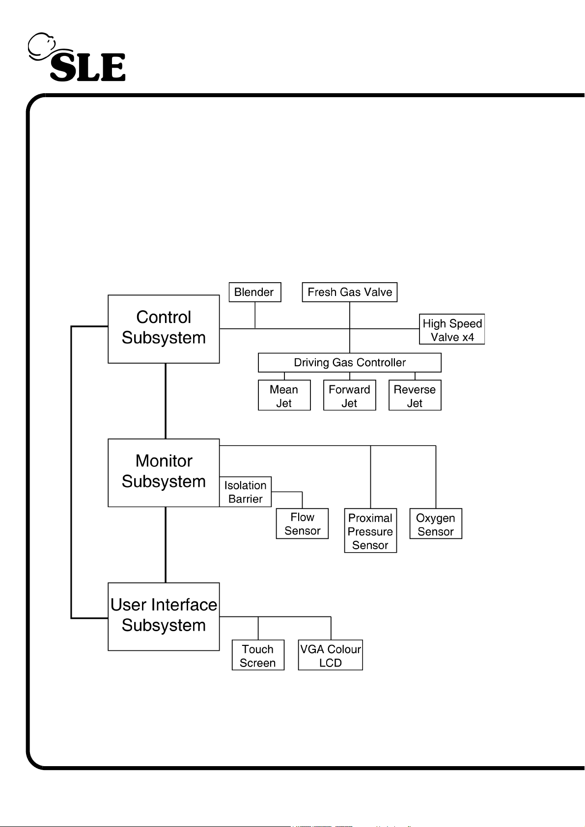
The electronic system comprises three autonomous subsystems, one responsible for
monitoring the patient, one responsible for controlling the valves of the pneumatic system
and one for the user interface (touchscreen and displayed data). They are connected
together by three serial communication links in a delta configuration.
The ventilator has an internal battery that can power the ventilator in the event of a mains
power fail. If the mains power fails with the battery fully charged, then operation will continue
for 30 to 60 minutes depending on ventilation mode.
See “Electrical Block Diagram” on page 378.
Page 14 (Model A)
Page 15

2.2 Pneumatic System
The pneumatic system comprises of the tubing and electro-mechanical valves necessary to
provide the gas in conventional and oscillatory ventilation modes. The two gas controlling
functions are blending and pressure generation
2.2.1 Blending
The method used for blending air and oxygen in known proportions is to pressure regulate
the two supplies (air and oxygen) so they produce equal flow rates and then allow each
supply into a mixing chamber for a time period equivalent to the proportions required. For
example, delivering oxygen at a set flow rate into a mixing chamber for 1 second and air at
the same flow rate for 2 seconds will result in a mixture of 1 part oxygen to 2 parts air
(resulting in a mix of 47.3%).
2.2.2 Pressure Generation
There are three nozzles within the exhalation block in the pneumatic subsystem. One for
generating negative pressure in the patient circuit and the other two for generating positive
pressure. The pressures generated from the three nozzles are controlled by three
electronically controlled pressure regulators. The negative and one of the positive nozzle
pressures can also be switched on and off rapidly with in-line (high speed) solenoid valves.
The other positive nozzle (the mean jet) is used to generate steady pressures in ventilation
(CPAP or PEEP pressures in conventional modes and mean pressures in HFO modes).
These three nozzles (or jets) are used in various combinations to generate all ventilation
modes.
2.2.3 Conventional ventilation
In non HFO modes the negative (or reverse) jet is used in a steady mode to provide a small
amount of flow to offset the inadvertent patient circuit pressure generated from the fresh gas
flow of 8 lpm. The mean jet is also used in a steady mode to generate the base pressure
level (CPAP or PEEP) and the forward jet is used to generate the PIP pressure during the
inspiratory phase. The rise time of the inspiratory phase is controlled by dynamically
controlling the forward jet pressure regulator rather than switching a steady pressure with
the high speed valves.
This provides a smooth rise in pressure and allows user adjustable rise times rather than
abrupt changes and pressure “ringing” which can result from high speed switching. The fall
of the inspiratory wave is also controlled by the forward jet pressure regulator to bring the
pressure down quickly and smoothly, using the high speed valves to do this would again
result in inadvertent ‘ringing’ which causes difficulties for the monitor subsystem in trying to
detect a patient breath attempt by monitoring the pressure alone. Once the pressure has
been brought close to the base pressure, after about 100 ms, the forward jet solenoid is
switched off to prevent any further artefact causing false triggering.
(Model A) Page 15
Page 16

Note that all jet pressures actually sum in the exhalation block, for example, to ventilate a
patient with a PEEP pressure of 5 mbar and a PIP pressure of 30 mbar, the mean jet will be
set to generate a continuous circuit pressure of 5 mbar and the forward jet will be set to
generate a circuit pressure varying between zero (exp phase) and 25 mbar (insp. phase).
Since the jet pressures will sum, this will result in the desired patient pressure.
2.2.4 HFO ventilation
In pure HFO mode the mean jet pressure regulator is used purely to set the mean pressure.
The forward and reverse jet pressure regulators are used to generate steady positive and
negative delta P components that will be superimposed on the mean pressure. These
components are switched quickly using the high-speed solenoid valves to generate the HFO
pressures.
For example to ventilate a patient with a mean pressure of 10 mbar and a delta P pressure
of 60 mbar, the mean jet will be set to generate a continuous pressure of 10 mbar, the
forward jet will be set to generate a continuous pressure of 30 mbar and the reverse jet will
be generating a continuous pressure of –30 mbar. The HFO rate is determined by the rate of
switching between the forward and reverse pressures on the high-speed valves. Again,
because the jet pressures sum, the resulting patient pressures will be switching between –
20 mbar and +40 mbar.
Mean HFO pressures up to 35mbar are required but the mean jet can only generate
pressures up to about 20 mbars. To obtain higher mean pressures than 20mbars in HFO it is
necessary to apply a higher pressure on the forward pressure regulator and a lower
pressure on the reverse pressure regulator. Using this method, the desired mean must be
less than half the desired delta p pressure plus 20 mbars.
See “Pneumatic Unit Schematic” on page 379.
Page 16 (Model A)
Page 17
Description of Symbols
(Model A) Page 17
Page 18
3. Description of Symbols
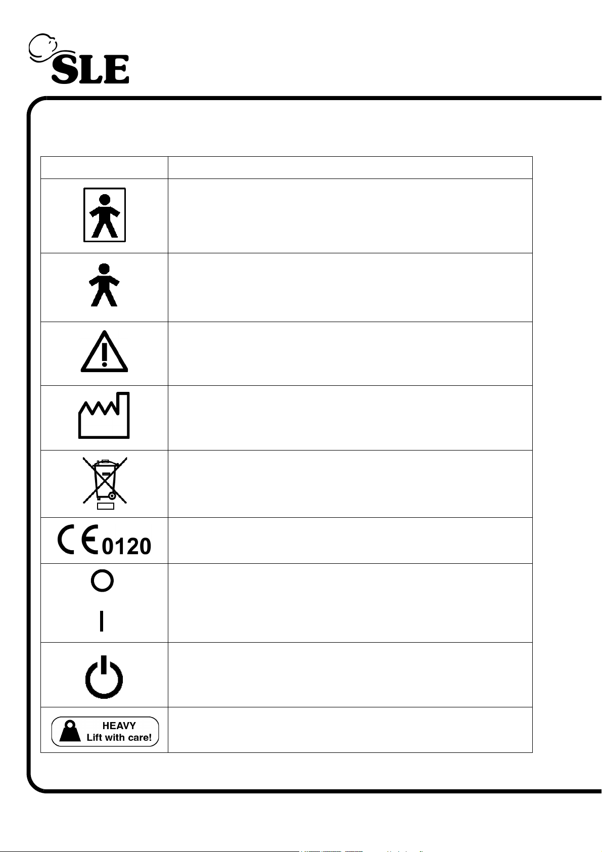
Symbol Description
Type BF connection (Situated on front panel)
Type B device (Situated on rear panel)
Read manual (Situated on rear panel)
Date of Manufacture (Appears on serial number label)
Do not dispose of as general waste (WEEE directive).
(Appears on serial number label).
EEC conformity marking showing compliance with the Medical
Devices Directive (Appears on serial number label)
Power Off
(Embossed on power switch)
Power ON
Indicates the mains power switch
Heavy, Lift with care (Situated on rear panel)
Page 18 (Model A)
Page 19
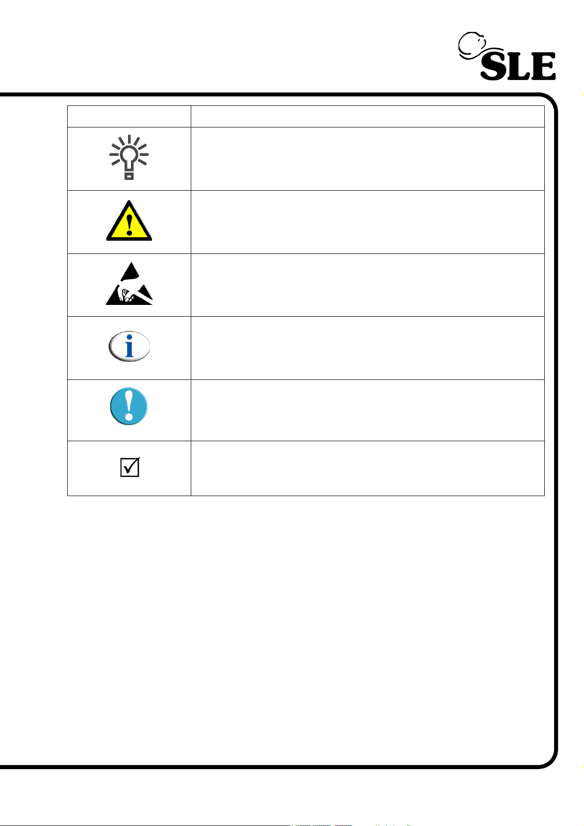
Symbol Description
Mains/Battery power indicator (Situated on front panel)
Indicates a warning in the manual
Observe anti static precuations
Indicates a note in the manual
Indicates a caution in the manual
Check list item.
(Model A) Page 19
Page 20

This page is intentionally blank.
Page 20 (Model A)
Page 21
Equipment List
(Model A) Page 21
Page 22

4. Equipment list
To service the SLE5000 infant ventilator the service personnel will require the following
equipment. Items marked with an SLE part number can be obatined by contacting the
service department.
• Electronic engineers tool kit.
a/b
•
•a Patient circuit ....................................................SLE Part Nº: N5188
•a Humidification chamber (MR220 ......................SLE Part Nº: N3220
•
•
•
•
•a ‘Y’ piece tube connector fitted with 0-2 bar reliving regulator on one limb.
•a Assorted tubing to connect analysers to ventilator.
•cStatic protection wrist band
•cAnti-static protective bags (300mm x 300mm)
•a Flow sensor cable.............................................SLE Part Nº: N6635
Calibration analyser (calibrated in mbar) .......SLE Part Nº: N2830
b
Test lung ...........................................................SLE Part Nº: N6647
c
Foam support pad
a
Digital Multimeter (1mv resolution)
a
24V power supply
•a Flow sensor ......................................................SLE Part Nº: N5201
•a Exhalation block ...............................................SLE Part Nº: N6622
•a Oxygen supply
•a Air supply
a
Note all items marked with an ‘a’ are required for servicing and overhaul. Without these
items the user will be unable to service or overhaul the SLE5000 ventilator.
b
Note items marked with a ‘b’ are required to carry out the functional testing routine.
Page 22 (Model A)
Page 23
Engineering Mode Software
(Model A) Page 23
Page 24
5. ENGMODE
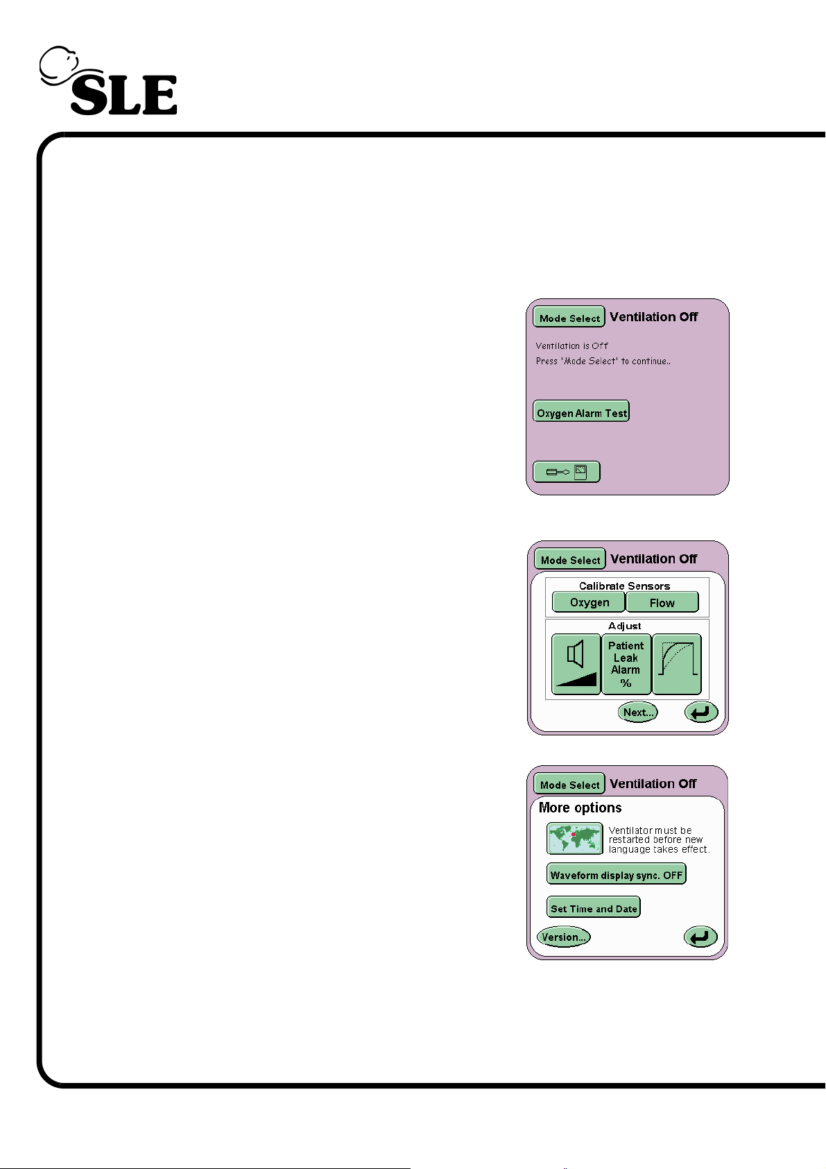
The SLE5000 ventilator is calibrated via two calibration programs, one for the
ventilator and one for the Touch screen. The calibration programs are accessed
via the Controller Services panel in the user interface.
5.1 Accessing the Calibration Programs
Step 1 Press the Options and Service Data
Button.
Step 2 Press the next button.
¦
Step 3 Press the version button.
Page 24 (Model A)
Page 25
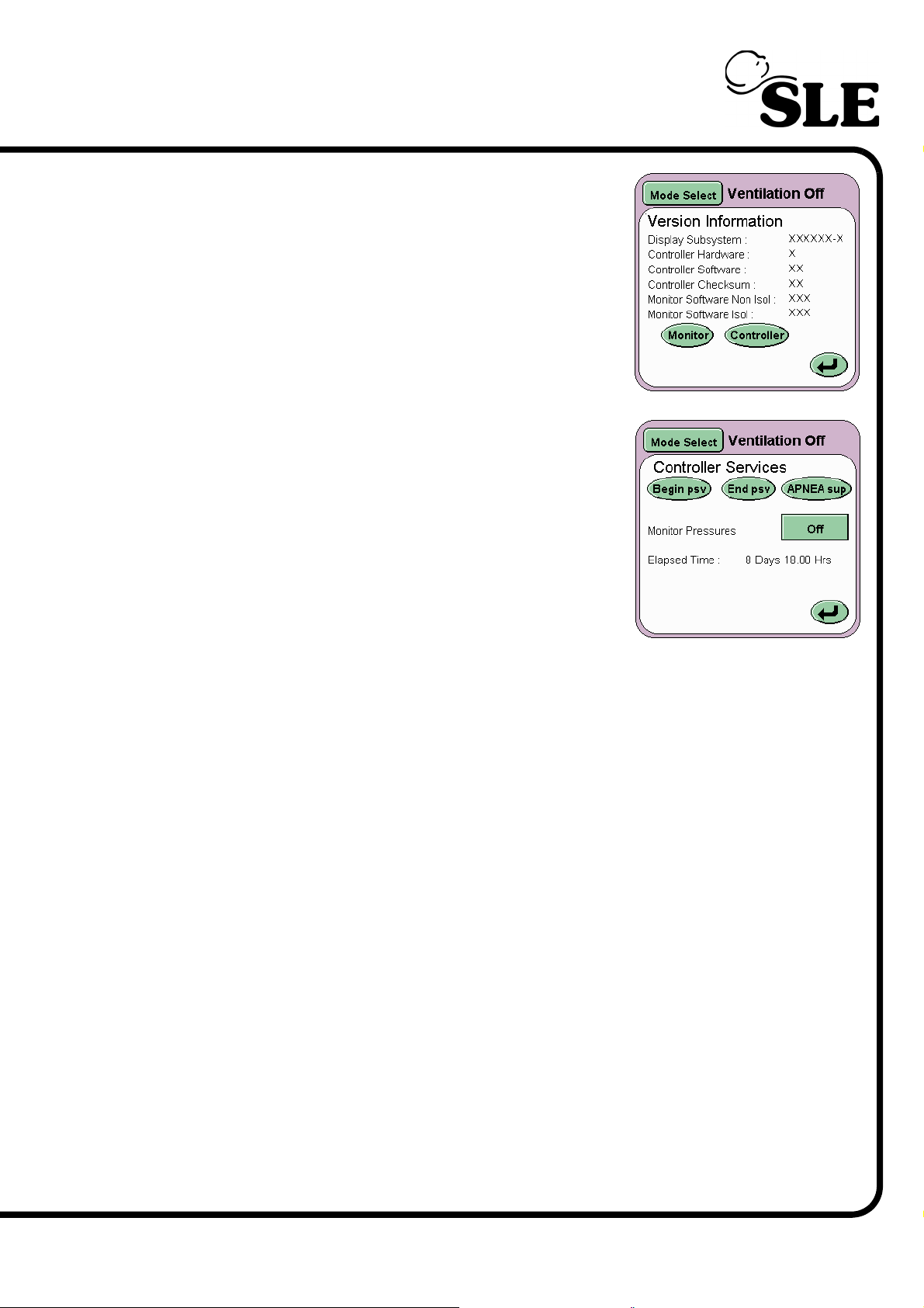
Step 4 Press the Controller button.
Step 5 Enter the code supplied by SLE into the
ventilator via the controller services panel to
activate the required calibration program.
Begin psv is the A button.
End psv is the B button.
Apnea sup is the C button.
Enter your code here____________________
(Model A) Page 25
Page 26
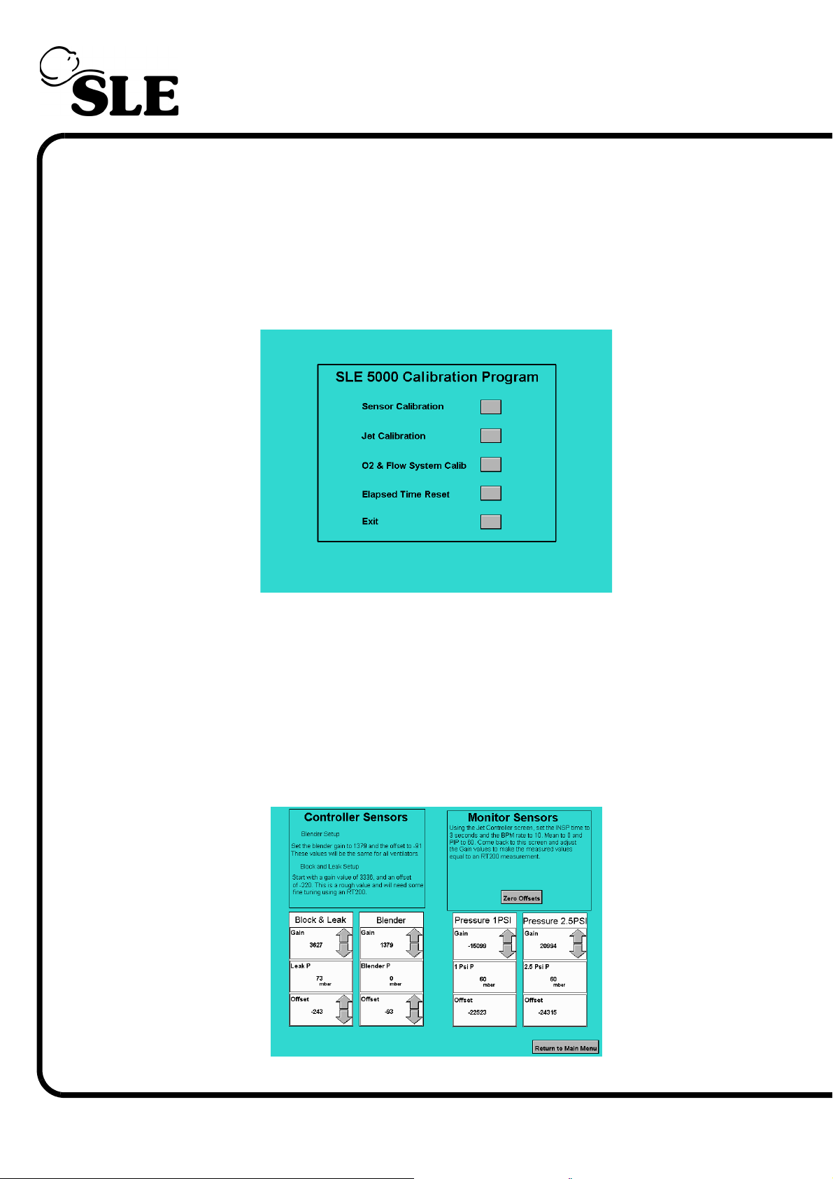
5.2 Ventilator Calibration Program
The calibration program has four main functions.
1. Sensor Calibration
2. Jet Calibration
3. O2 & Flow System Calibration
4. Elapsed Time Reset.
5. Exit
5.2.1 Sensor Calibration
The sensor calibration panel allows the following sensors to be calibrated.
Controller
The setting of the Block and leak sensor Offset and Gain.
The setting of the Blender sensor Offset and Gain.
Monitor
The setting of the Blender sensor Gain.
Page 26 (Model A)
Page 27
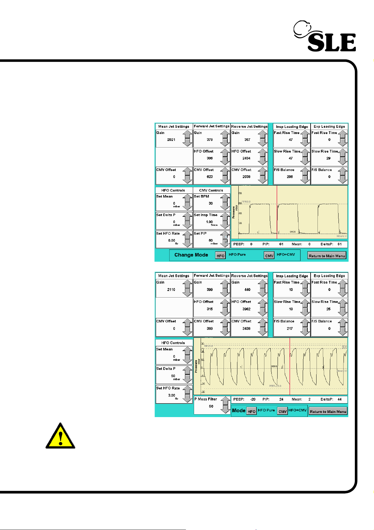
5.2.2 Jet Calibration
The jet calibration panel allows the forward jet, reverse jet and mean jet to be
adjusted. Also contained within this panel are the controls to adjust the inspiratory
and expiratory leading edges of the CMV wave form. Associated controls to set
the ventilator in CMV or HFO mode are also displayed.
Layout for Version
3 to 3.2 software
Layout for Version
3.3 software
Warning: Version 3.3 software has a new parameter the “P Meas Filter”. This
is a low pass filter which removes high frequency components from the
displayed waveform.
This is required as the new N6623/33 pressure regulators produce a greater
initial high frequency component. N6623/33 pressure regulator can only be
used in conjunction with version 3.3 software.
(Model A) Page 27
Page 28
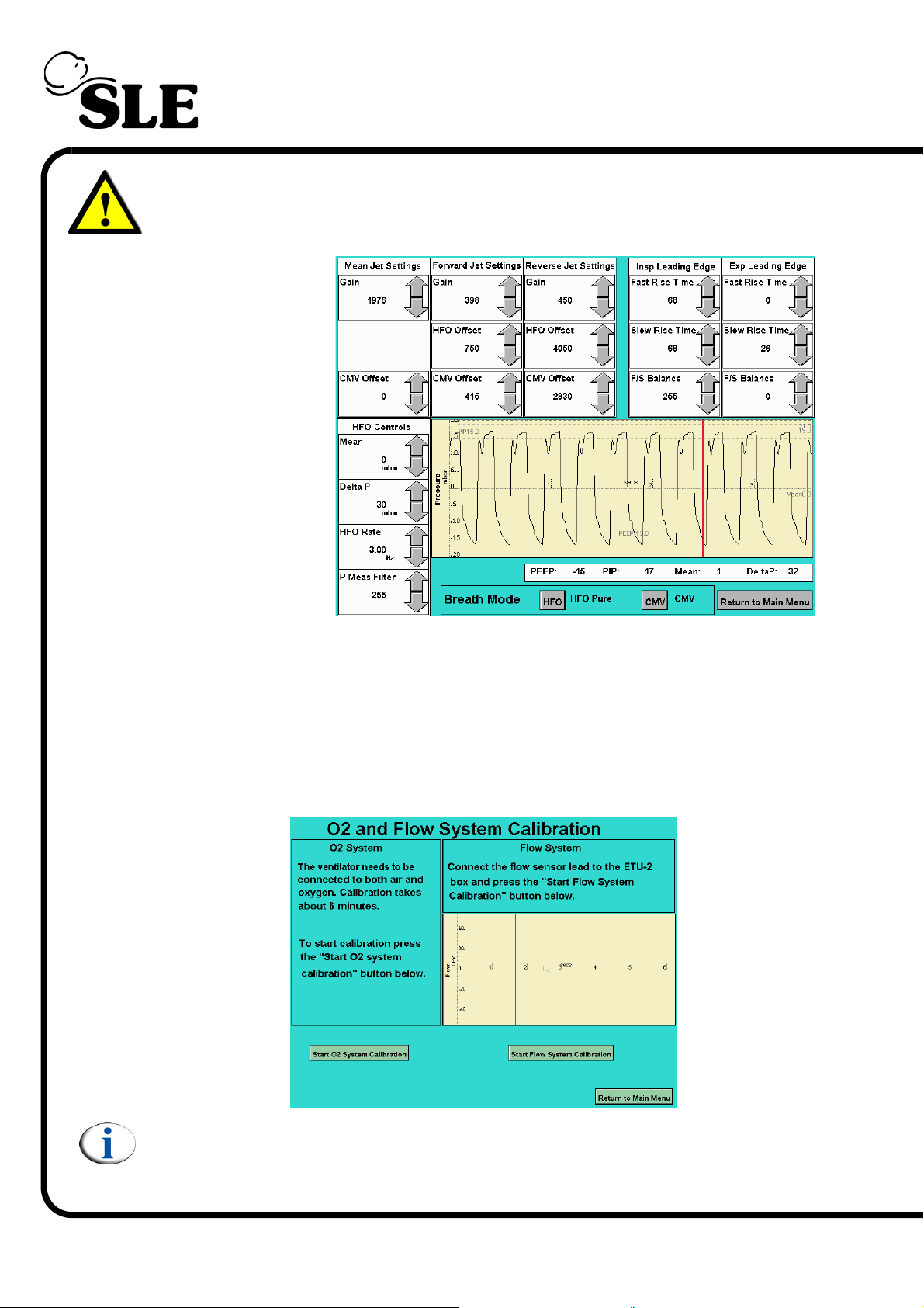
Warning: N6623/33 regulators cannot be used with version 3 to 3.2 software
as the high frequency component can not be removed making the ventilator
unusable.
Layout for Version
4 software
5.3 O2 & Flow System Calibration
The O2 & Flow System Calibration panel allows the calibration of the oxygen
monitoring system (2 point calibration, 100% and 21%) and the calibration of the
flow system.
The flow system is a factory set system and requires an ETU-2 for calibration.
Note: For version 3.3 & 4 software O
Page 28 (Model A)
calibration time is 7 minutes.
2
Page 29
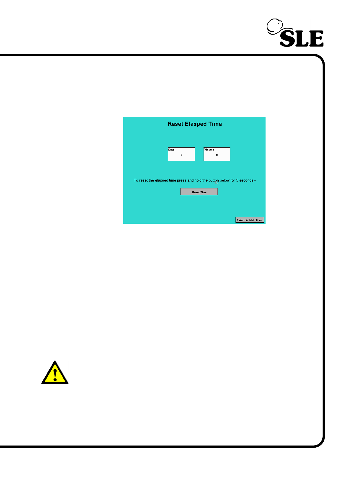
5.4 Reset Elapsed Time
The reset elapsed time panel allows the ventilators time counter to be reset to
zero days and minutes.
This function is only used at the 20,000 hour overhaul.
5.5 Exit
The exit button will return the user to a DOS prompt. To return to the ventilator to
its normal operating mode, restart the ventilator.
5.6 Touch Screen Calibration Program
The touch screen calibration program is accessed by the same method as for the
calibration program. See ’5.1 Accessing the Calibration Programs’ on page 24.
Enter you code here____________________
Four the touch screen please follow the on screen instructions.
To return to the ventilator to its normal operating mode, restart the ventilator.
Warning: Failure to carry out the touch screen calibration correctly can
cause the ventilator to become unusable. A failed touch screen calibration
can only be corrected by connection of a specialist device. Please contact
SLE or your distributor in this situation.
(Model A) Page 29
Page 30

This page is intentionally blank.
Page 30 (Model A)
Page 31
Component Replacement
(Model A) Page 31
Page 32

6. Component Replacement Procedure
The component replacement procedures detailed in this chapter describes how to
replace the individual component in isolation. Each procedure details what setup
is required to return the ventilator to service. After completing any or all of the
following procedures a full functional test as described in this manual must be
carried out.
The following replacement and setup procedures are detailed in this chapter.
Electronic unit
• CAN card .................................................. SLE Part Nº: N6634
• PC battery ................................................. SLE Part Nº: M0909
• Disk on chip .............................................. SLE Part Nº: D0724
• Computer Board........................................ SLE Part Nº: N6631/01
• Serial controller (Touch screen) ................ SLE Part Nº: N6631/06
• Control and monitor board ........................ SLE Part Nº: A0763/02
• Power supply unit...................................... SLE Part Nº: M0900
• Batteries.................................................... SLE Part Nº: M0901
• Transducer PCB assembly ....................... SLE Part Nº: A0761
• LCD........................................................... SLE Part Nº: N6631/02
• Touch screen............................................. SLE Part Nº: N6631/05
• Inverter PCB ............................................. SLE Part Nº: N6631/03 or /10
Pneumatic Unit
• Conical and Duckbill filters........................ SLE Part Nº: N2185/06 & /05
• Blender...................................................... SLE Part Nº: L0287
• Fresh gas bypass solenoid SV7 ............... SLE Part Nº: N2195/06
• Purge regulator PR7 ................................. SLE Part Nº: N6612
• Regulator PR5 .......................................... SLE Part Nº: N6613
• Speed controller FR1 ................................ SLE Part Nº: N6614
• Regulator input air PR1............................. SLE Part Nº: N6615/01
• Regulator input oxygen PR2 ..................... SLE Part Nº: N6615/02
• High speed jet valves SV9, 10, 11 & 12 .... SLE Part Nº: N6624
• Pressure regulators PR3, PR4 & PR6 ...... SLE Part Nº: N6623 /33 or /S38
Page 32 (Model A)
Page 33
7. Preparing the SLE5000
Caution: the SLE5000 ventilator weighs 23.6kg fully assembled. Care
should be taken when handling the ventilator.
If preparing to work on both the electronic and pneumatic units of the SLE5000
remove the ventilator from the stand and place it on a flat stable surface. The
SLE5000 ventilator is attached to the trolley or pole by two screws with shake
proof washers. Retain the screws and washers for re-attachment of the ventilator.
If work is to be carried out on the electronic unit only it is advisable to leave the
ventilator attached to the trolley.
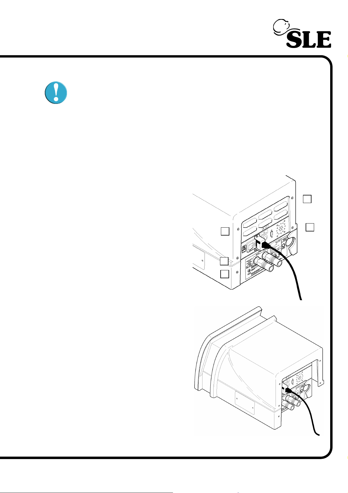
Step 1 Remove the 5 fixing screws
(A) indicated from the rear cover.
¦
A
¦
A
¦
A
Step 2 Slide the rear cover towards
the rear of the machine. When the lip
has been disengaged lift the cover
off.
A
A
¦
¦
¦
(Model A) Page 33
Page 34
Warning: If the ventilator
is under a warranty agreement removal of the inner
covers may void the
agreement. Please refer to
the warranty documentation.
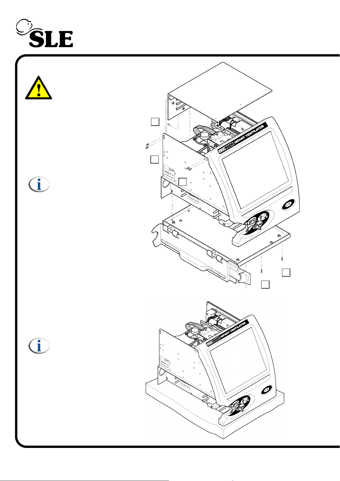
Step 3 Remove the
screws (B) (10 screws) to
release the electronic inner
cover.
Note: The design of the
inner cover may vary.
B
¦
¦
B
¦
B
Step 4 Remove the
screws (C) (6 screws) to
release the pneumatic unit
base plate.
Step 5 Rest the ventilator
on a soft pad.
Note: Keep the ventilator
plugged into the mains
supply, but with the
supply turned off. This is
to earth the ventilator and
prevent static build up.
C
¦
¦
C
Page 34 (Model A)
Page 35
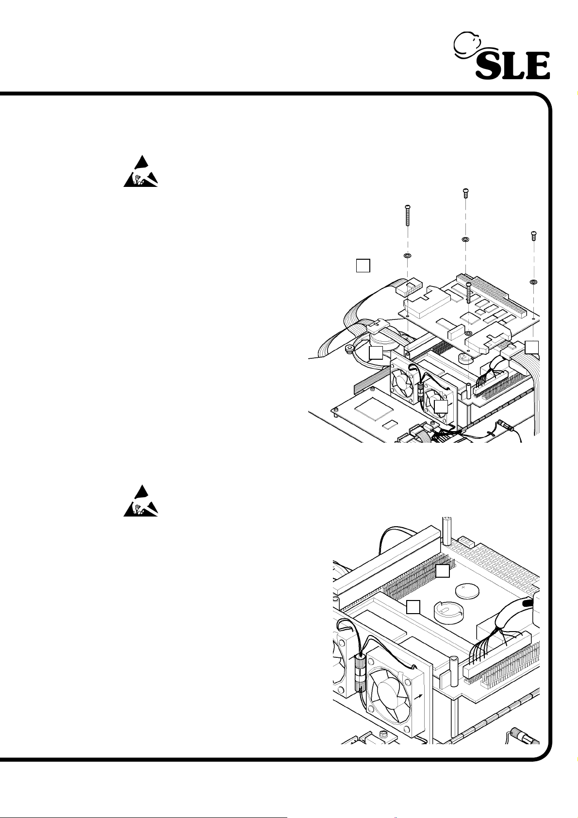
8. Component Replacement (Electronic unit)
8.1 N6634 CAN Card
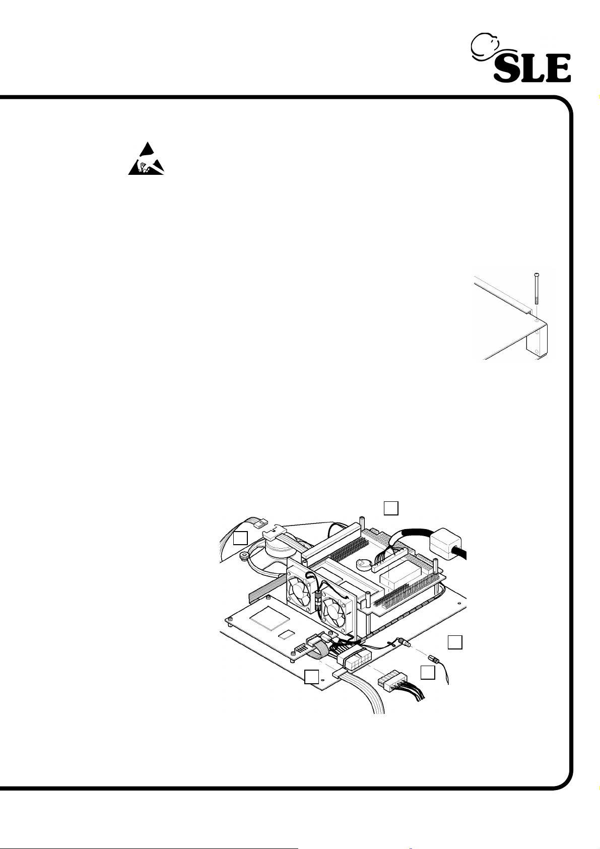
Warning: the CAN Card is a static sensitive device.
1. Disconnect the two ribbon
cables (A & B) from the CAN card.
2. Remove the four screws
retaining the CAN card.
3. Gently disconnect the CAN card
from the PC board by lifting the
card vertically, until all the
connector pins are disengaged
from the socket.
4. The two nylon spacers (C) are
now loose. Care should be taken to
prevent them falling into the
electronic unit.
5. Assembly is reversal of removal.
A
¦
C
¦
B
¦
¦
C
Setup: No setup is required for this
device.
8.2 BIOS battery
Warning: The PC board is a static sensitive device.
1. Remove the CAN card as described
in section 8.1
2. Remove the battery (A) from the
battery housing (B)
3. Assembly is reversal of removal.
4. Re-assemble the ventilator and turn it
on.
Setup: Enter the “More Options” panel
of the user interface and reset the time
and date.
A
¦
B
¦
(Refer to the user manual for more
details on how to set the time and date.)
(Model A) Page 35
Page 36
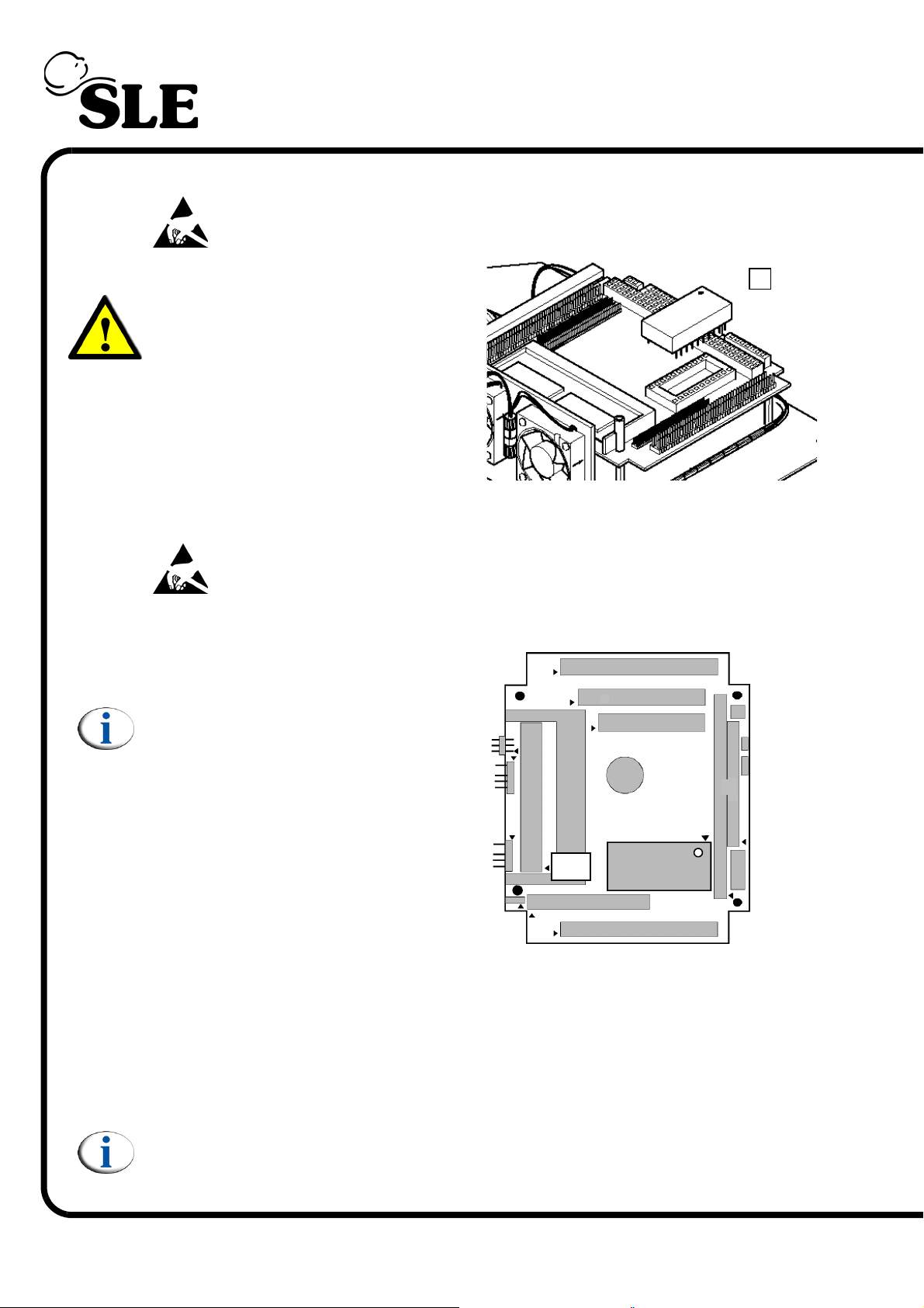
8.3 Disk-on-Chip
Warning: The PC board is a static sensitive device.
Warning: Failure to fit the Disk-onChip correctly will cause the Diskon-Chip and the N6631/01 PC board
to fail.
1. Remove the can card as described in
section 8.1
2. Remove the Disk-on-Chip (A) using
an IC extraction tool.
Warning: Protect the Disk-on-Chip from static damage by placing
the pins in anti static foam and the complete chip in an anti static
bag.
¦
A
3. Insert the new Disk-on-Chip into the
IC15 socket on the N6631/01 board.
Note: Make sure that Pin 1 on the
Disk-on-Chip and the N6631/01 PC
board correspond.
4. Re-assemble the ventilator and turn it
on.
IC15
Setup:
For a Disk-on-Chip with the same version of software, touch screen calibration,
reset the time / date and full functional test.
For a Disk-on-Chip with the a new version of software, touch screen calibration,
full system calibration, reset the time / date and full functional test.
¦
Pin 1
Note: Software upgrades are usually in conjunction with upgrades to other
programmable devices on the control monitor board.
Page 36 (Model A)
Page 37
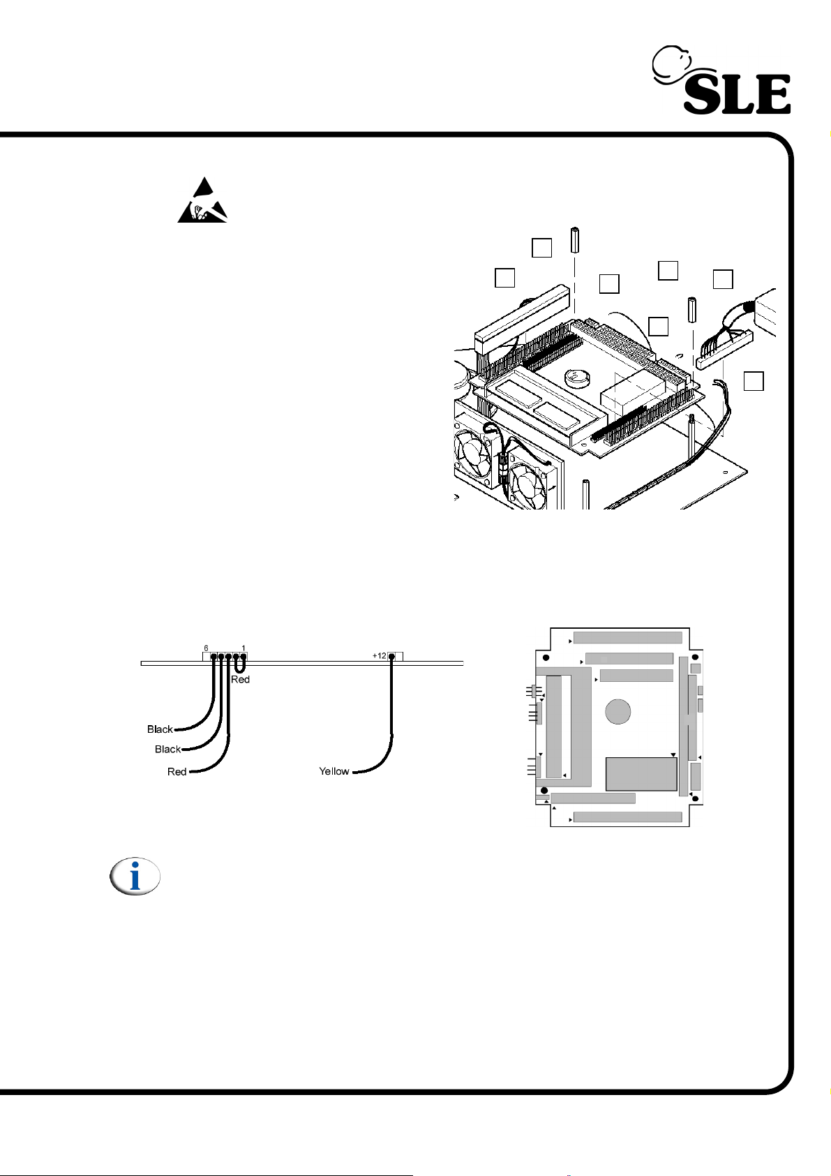
8.4 N6631/01 PC Board
Warning: The PC board is a static sensitive device.
1. Remove the CAN card as
described in section 8.1.
2. Unscrew the two pillars (A).
3. Disconnect the 50 way connector
(B).
4. Disconnect the display connector
cable (C).
5. Disconnect the wires (D & E).
6. Remove the link wire (F).
Assembly is the reverse of removal.
Connect the wires D to P18, E to P26 and link wire F to P18 as per figure 1.
Reconnect the 50 way connector B to P22 and the display connector cable C to
P6 as per figure 2.
B
¦
A
¦
¦
E
F
A
¦
¦
C
¦
¦
D
P18
P26
P22
¦
¦
Fig. 1
Fig. 2
Note: Check that the new PC board has been pre-programmed with the
correct version of software. (Refer to the accompanying documentation).
7. Re-assemble the ventilator and turn it on.
Setup: If the original Disk-on-chip has been used, touch screen calibration, reset
the time / date and full functional test.
If a new Disk-on-chip has been fitted or a supplied with the board, touch screen
calibration, full system calibration, reset the time / date and full functional test.
P6
(Model A) Page 37
Page 38
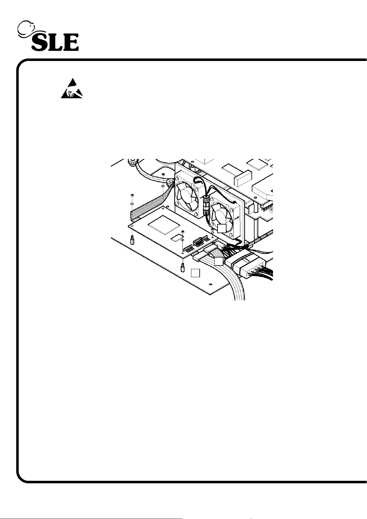
8.5 N6631/06 Serial controller (Touch screen)
Warning: The Serial controller is a static sensitive device.
1. Disconnect the touch screen ribbon cable (A) from the board.
2. Disconnect the PC link ribbon cable (B) from the board.
3. Disconnect the power cable (C) from the board.
C
¦
¦
¦
B
A
4. Remove the four nuts and washers retaining the serial controller PCB.
5. Remove the serial controller PCB.
6. Assembly of the serial controller PCB is the reverse of removal.
Setup: Touch screen calibration.
Page 38 (Model A)
Page 39
8.6 A0763/02 Control and Monitor Board
Warning: The Control and Monitor Board is a static sensitive device.
1. Remove the CAN card as described in section 8.1.
2. Remove the PCB locking screw. This will allow the top board assembly to slide
forward a small amount which gives better access to the edge connectors of the
top board.
3. Disconnect the display connector cable (A).
4. Disconnect the cooling fan power supply connector (B).
5. Disconnect the board power connector cable (C).
6. Disconnect the touch screen connector cable (D).
7. Disconnect the RS232 connector cable (E)
A
¦
E
¦
D
¦
¦
¦
C
B
8. The PC carrier board can now be removed by sliding towards the rear of the
ventilator.
(Model A) Page 39
Page 40
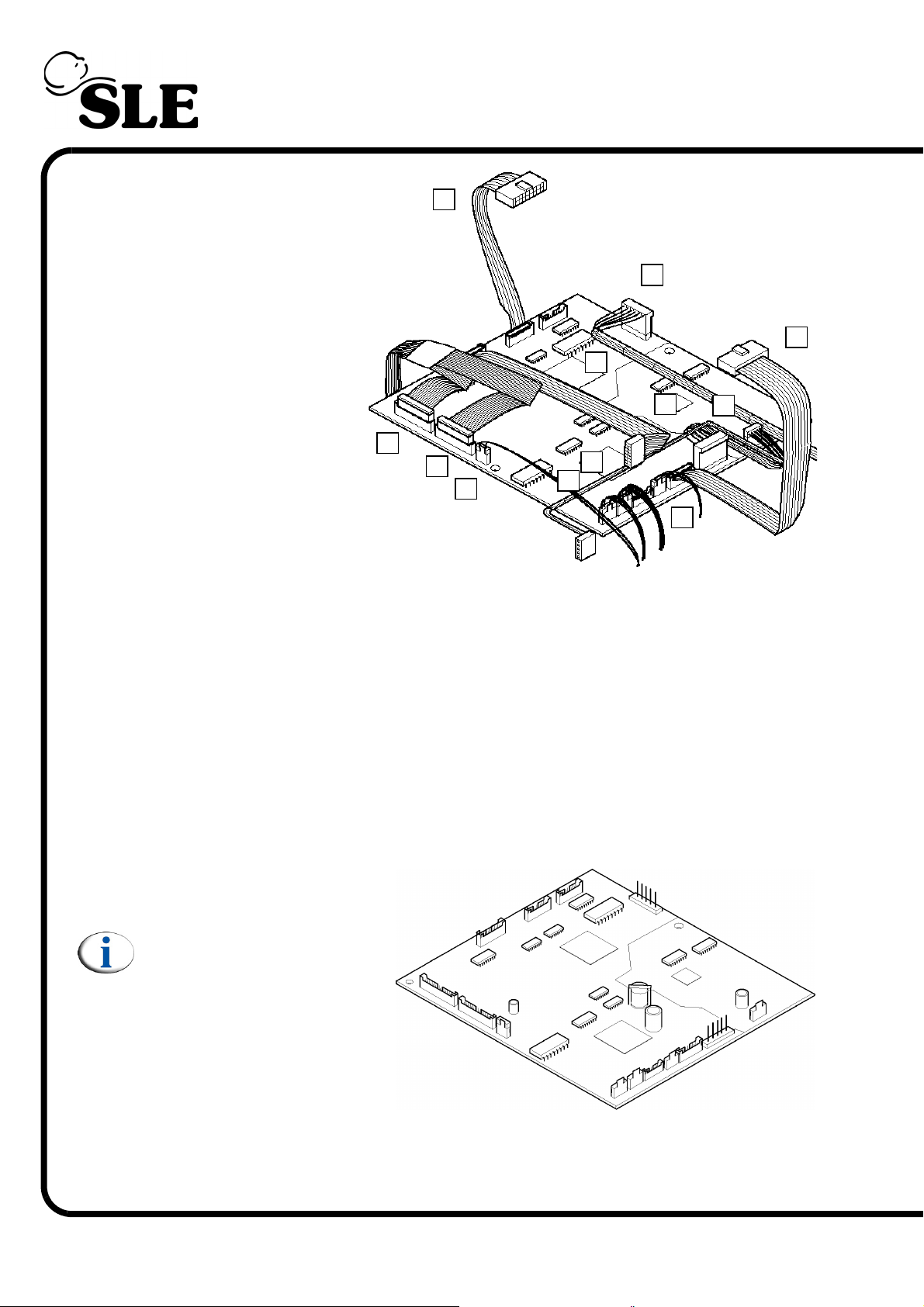
The Control monitor
board can now be
accessed.
9. Disconnect the
following cables.
10. CAN card link ribbon
cable controller side (F).
(P3)
11.CAN card link ribbon
cable controller side (G).
(JP3)
12. Power supply
connector controller side,
main loom (H). (P4)
13. Controller to A0761
transducer assembly
ribbon cable (I). (P5)
14. Conventional valve drive ribbon cable (J). (P6)
J
F
¦
K
¦
¦
¦
L
¦
M
I
N
¦
¦
¦
H
P
¦
¦
O
G
¦
Q
¦
15. Analogue valve drive ribbon cable (K). (P7)
16. Alarm sounder cable, main loom (L). (JP5)
17. Battery/power supply sensing connector, main loom (M). (JP9)
18. Controller to A0761 transducer assembly connector (N). (JP7)
19. O
20. Power supply connector monitor side, main loom (P). (JP6)
21. Flow sensor connector (Q). (JP4)
22. The control and monitor
board can now be removed.
Note: For a detailed
description .Refer to
“A0763/02 Monitor and
control board” on page
74.
Assembly is the reversal of
removal.
cell connector (O). (JP8)
2
Setup: A full system calibration is required for this component.
Page 40 (Model A)
Page 41
8.7 M0900 Power Supply Unit
1. Disconnect the main
power supply.
2. Remove the four fixing
screws.
3. Disconnect the battery
monitor cable (A).
A
¦
¦
4. Disconnect the main loom
power cable (B).
5. Disconnect the battery
monitor cable (C).
6. Lift the power supply to
reveal the mains inlet cable
(D).
7. Disconnect the mains inlet
cable and remove the power
supply.
8. Assembly is reversal of
removal.
Setup: No setup is required for this device.
B
¦
C
D
¦
(Model A) Page 41
Page 42
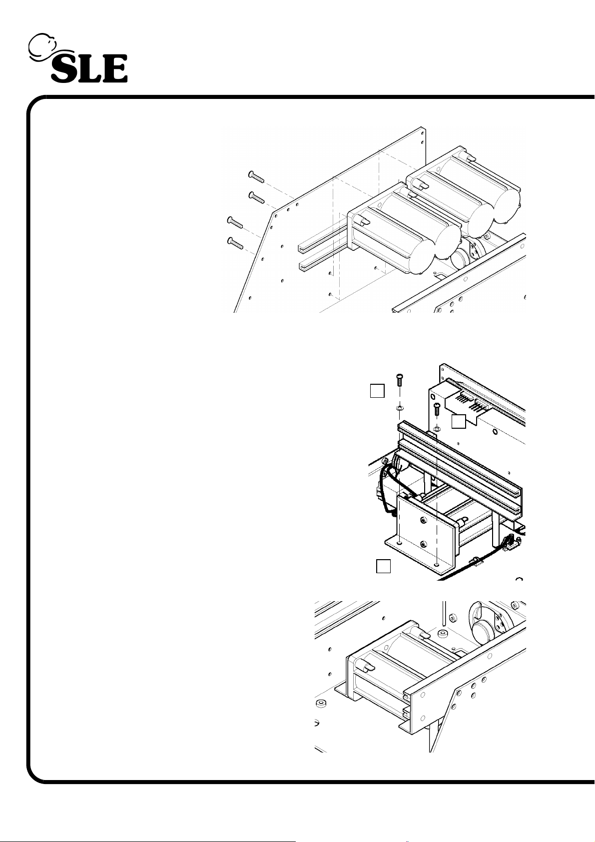
8.8 M0901 Batteries
1. Remove the CAN
card as described in
section 8.1.
2. Remove the PC
board and the monitor
control board as
described in section
8.6.
3. Disconnect all the
battery terminal leads.
4. Remove the four
retaining screws for
the first two battery
blocks.
5. Remove the two batteries.
A
¦
¦
A
6. Remove the two fixing screws and washers
(A), securing the fixing bracket (B) for the third
battery.
7. Slide the battery forward and lift clear.
8. Remove the two fixing screws to
release the bracket from the battery
block.
9. Assembly is reversal of removal.
Setup: No setup is required for this
device. The ventilator should be left
connected and turned on for a minimum
of 24 hours to fully charge the batteries.
B
¦
Page 42 (Model A)
Page 43
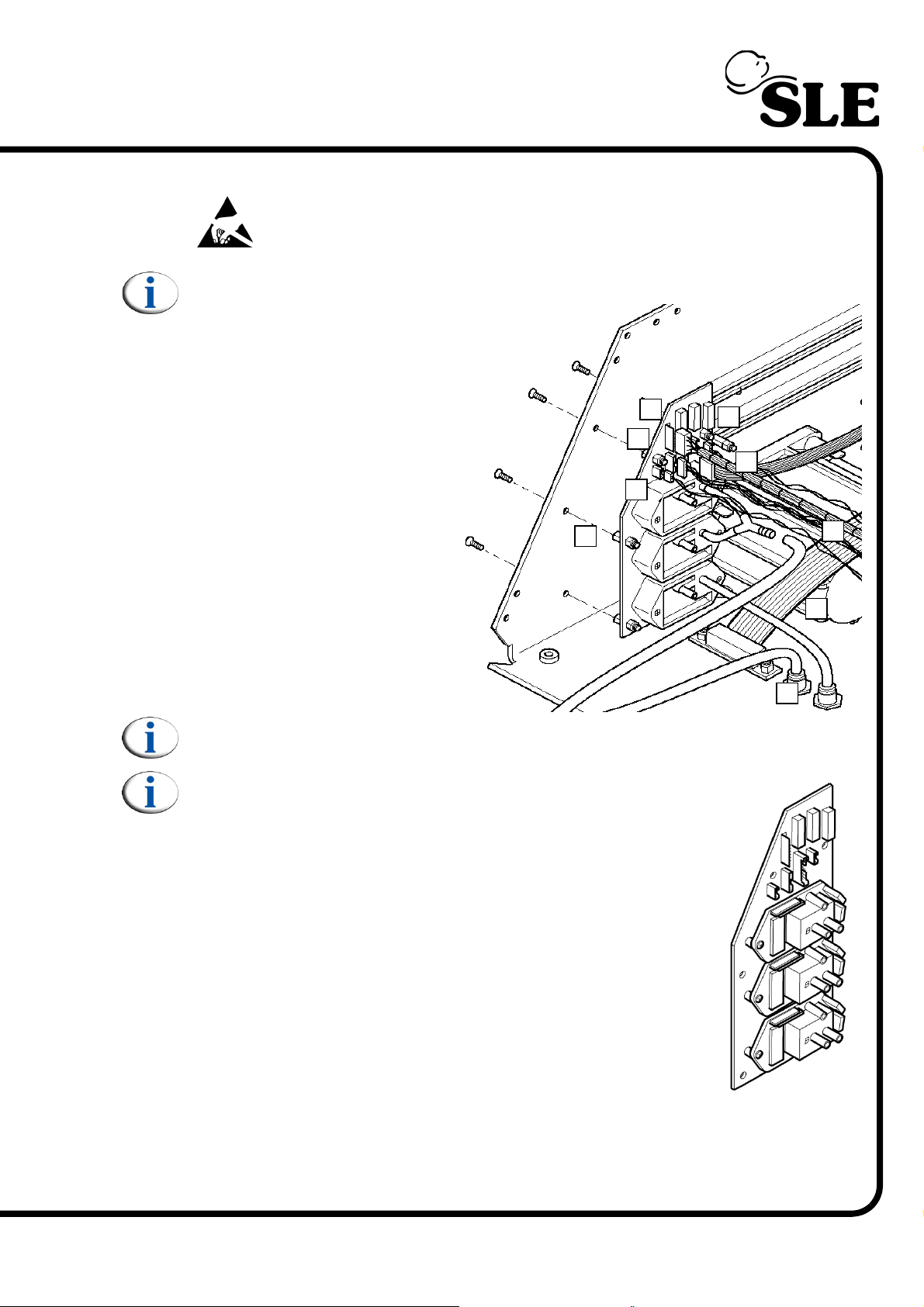
8.9 A0761 Transducer PCB Assembly
Warning: The Transducer PCB is a static sensitive device.
Note: Screen removed for clarity.
1. Remove the CAN card as
described in section 8.1.
2. Remove the PC board and
the monitor control board as
described in section 8.6.
3. Disconnect the ribbon cable
from J2 (A).
C
B
D
¦
¦
¦
¦
¦
E
A
4. Disconnect the main loom
connector from J5 (B).
5. Disconnect the LED
connector from J4 (C).
6. Disconnect the loom
connector from J3 (D).
7. Disconnect the loom
connector from J1 (E).
Note: The tubes connected to the transducer PCB are attached using an
adhesive.
Note:Please note that replacement assemblies use an
open pcb tansducer. (Ventilator serial N° 51859 onwards).
8. Remove the tube (F) from the Y piece connector.
9. Remove the tube (G) from the bulk head connector (H).
10. Remove the six fixing screws retaining the transducer PCB.
11. Remove the support pillars, retaining nuts and washers (I)
from the old PCB and transfer them to the replacement PCB.
I
¦
¦
H
¦
G
¦
F
12. Assembly is reversal of removal.
Setup: A full system calibration is required for this component.
(Model A) Page 43
Page 44
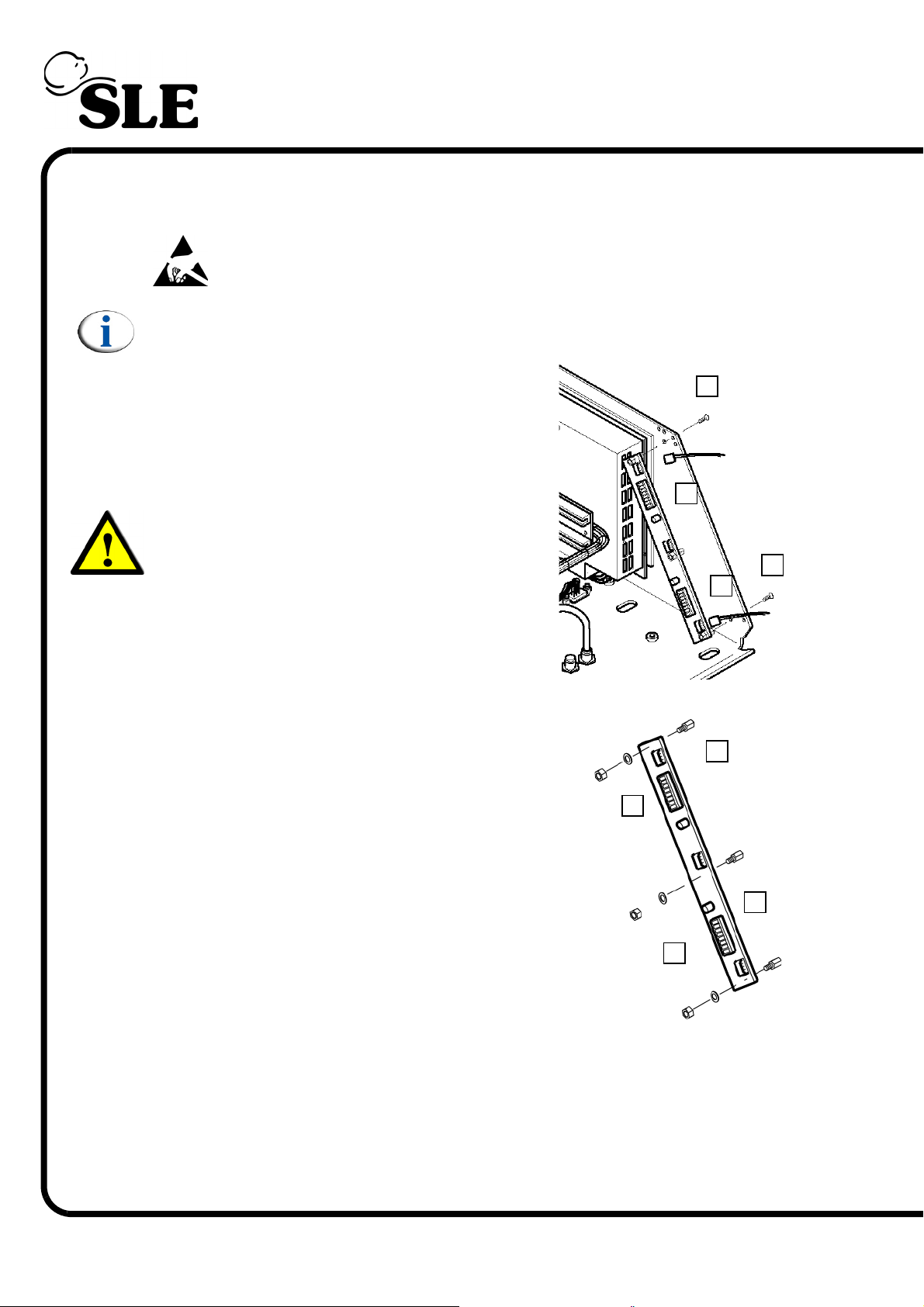
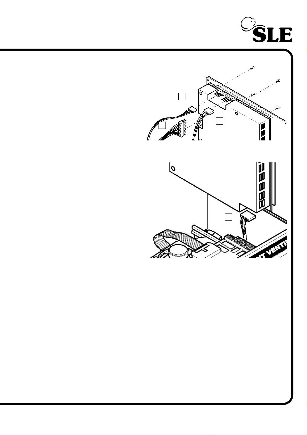
8.10 Inverter PCB
8.10.1 N6631/03 Inverter PCB
Warning: The Transducer PCB is a static sensitive device.
Note: Screen removed for clarity.
1. Remove the CAN card as described in section
8.1.
2. Remove the PC board and the monitor control
board as described in section 8.6.
3. Remove the two screws (A).
Warning: The PCB is still attached by the
backlight connectors to the LCD / Touch
screen assembly.
4. Disconnect the two backlight connectors (B).
5. Remove the PCB from the electronic unit.
6. Remove the three support pillars (C) by
removing the nut and washers (D).
7. Assembly is reversal of removal.
Setup: No setup is required for this device.
¦
D
¦
¦
B
A
B
¦
¦
C
A
¦
¦
¦
D
C
¦
¦
Page 44 (Model A)
Page 45
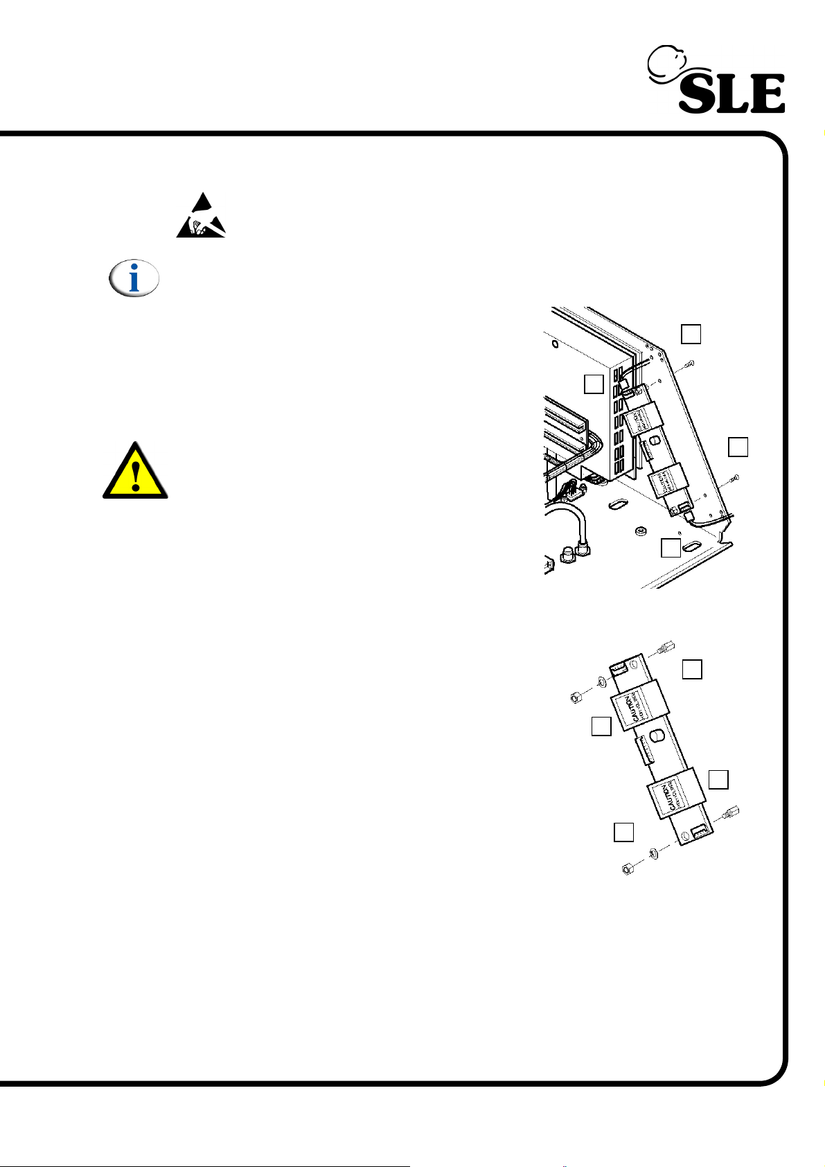
8.10.2 N6631/10 Inverter PCB
Warning: The Transducer PCB is a static sensitive device.
Note: Screen removed for clarity.
1. Remove the CAN card as described in section
8.1.
2. Remove the PC board and the monitor control
board as described in section 8.6.
3. Remove the two screws (A).
B
A
¦
¦
Warning: The PCB is still attached by the
backlight connectors to the LCD / Touch
screen assembly.
4. Disconnect the two backlight connectors (B).
5. Remove the PCB from the electronic unit.
6. Remove the two support pillars (C) by
removing the nut and washers (D).
7. Assembly is reversal of removal.
Setup: No setup is required for this device.
A
¦
¦
B
¦
C
¦
D
C
¦
D
¦
(Model A) Page 45
Page 46
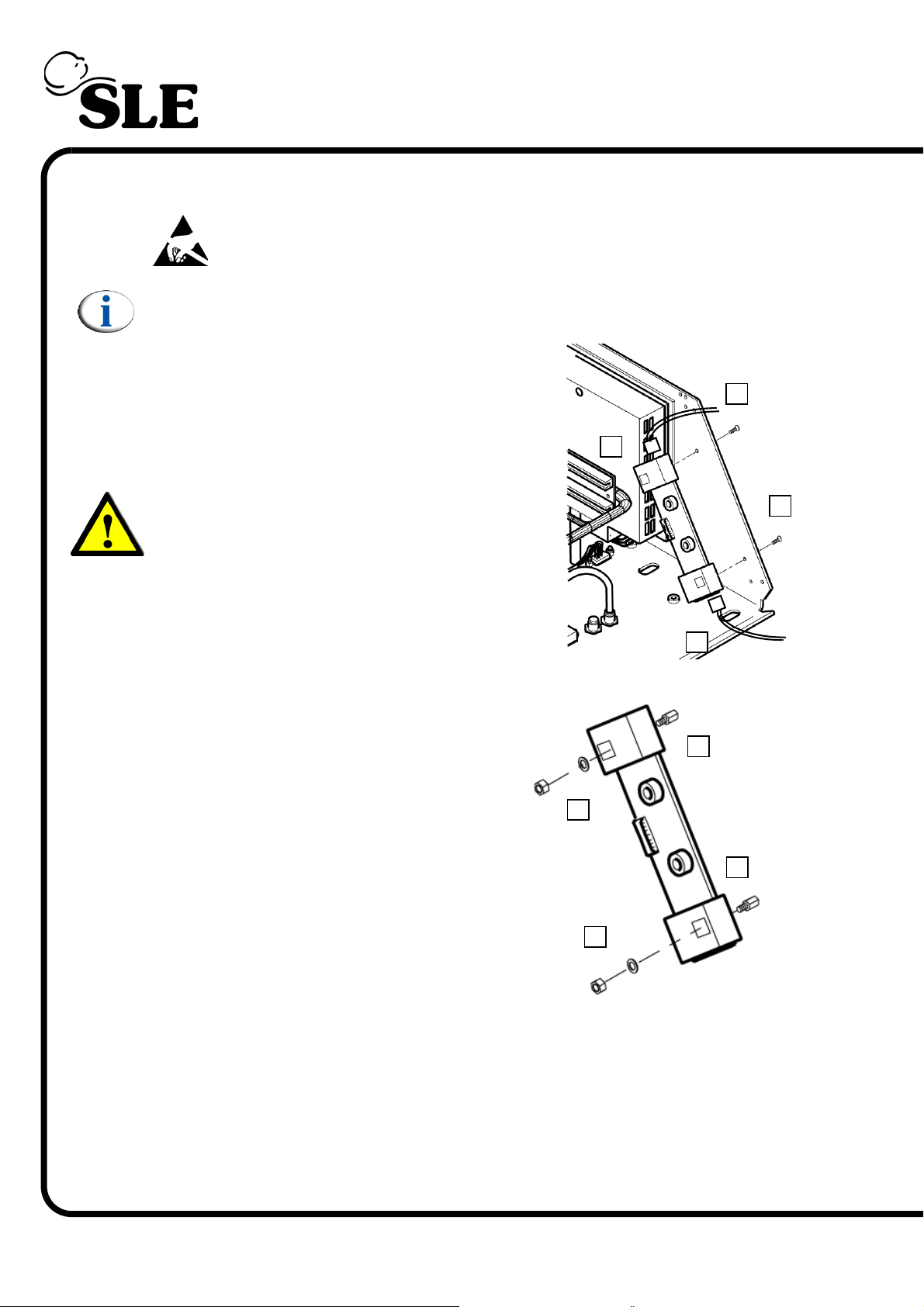
8.10.3 N6631/13 Inverter PCB
Warning: The Transducer PCB is a static sensitive device.
Note: Screen removed for clarity.
1. Remove the CAN card as described in section
8.1.
2. Remove the PC board and the monitor control
board as described in section 8.6.
3. Remove the two screws (A).
B
A
¦
¦
Warning: The PCB is still attached by the
backlight connectors to the LCD / Touch
screen assembly.
4. Disconnect the two backlight connectors (B).
5. Remove the PCB from the electronic unit.
6. Remove the two support pillars (C) by
removing the nut and washers (D).
7. Assembly is reversal of removal.
Setup: No setup is required for this
device.
A
¦
¦
B
¦
C
¦
D
C
¦
D
¦
Page 46 (Model A)
Page 47
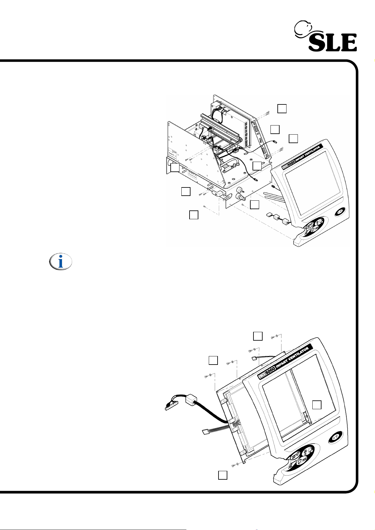
8.11 N6631/02 LCD & N6631/05 Touch Screen
8.11.1 For ventilators 51010 to 51084
1. Remove the CAN
card as described in
section 8.1.
¦
A
2. Remove the PC
board and the monitor
control board as
described in section 8.6.
¦
3. Remove the 8 screws
(A) retaining the screen
tie bars.
4. Remove the 3
remaining facia
retaining screws (B).
5. Gently draw the front
panel assembly away
from the unit.
Note: Display / touch screen cables not shown for clarity.
6. Disconnect the two backlight power leads from the inverter board
(See section 8.10 on page 44).
7. Disconnect the two tubes (C).
8. Disconnect the fan electrical connector (D).
A
A
B
¦
¦
¦
C
E
D
¦
¦
¦
A
9. Disconnect the led electrical connector (E).
10. Remove the 6 facia
retaining screws and
washers (F).
11. Remove the front
facia.
F
¦
F
¦
¦
¦
F
¦
F
¦
(Model A) Page 47
Page 48
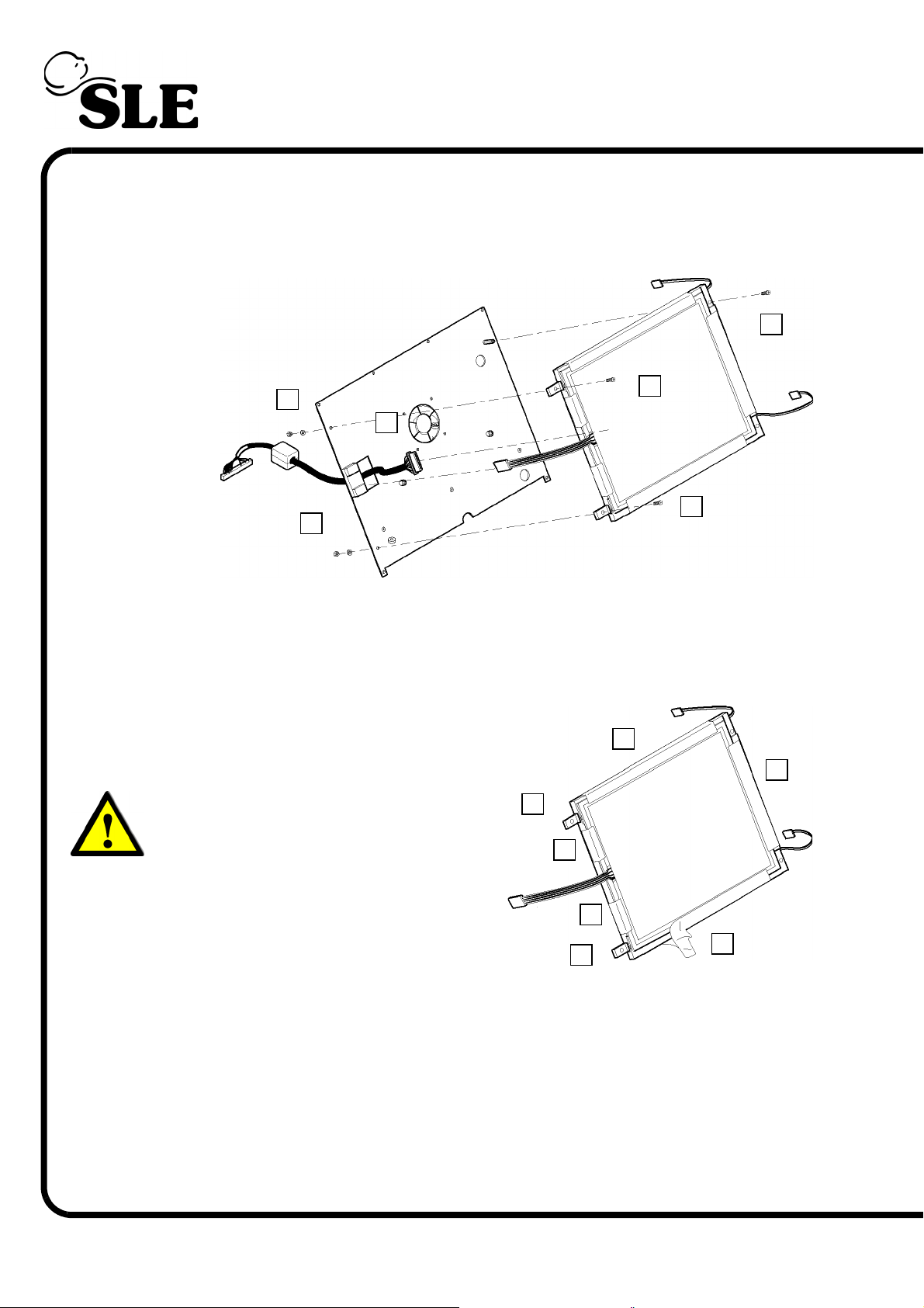
12. Remove the 2 screws (G) retaining the right hand side of the LCD / touch
screen assembly.
13. Remove the 2 nuts, washers (H) and screws (I) retaining the left hand side of
the LCD / touch screen assembly.
¦
G
¦
H
¦
J
I
¦
¦
I
H
¦
14. Separate the LCD / touch screen assembly from the mounting plate.
15. Disconnect the connecting cable (J) from the rear of the LCD assembly.
16. The LCD / touch screen assembly is now free.
17. To remove the touch screen, peel off
the adhesive tape (L).
18. Once the tape is remove the touch
screen can be removed.
Warning: Do not touch the LCD screen
with bare hands. This is to prevent
grease contamination of the surface
(i.e. finger prints).
M
¦
L
¦
L
¦
¦
L
19. With the touch screen removed the
two LCD mounting blocks (M) can be
removed as access to their fixing screws
is now possible.
20. Assembly is reversal of removal.
Setup: If the entire assembly or just the touch screen has been replaced the
screen calibration routine will have to be carried out.
Page 48 (Model A)
M
L
¦
¦
¦
L
Page 49
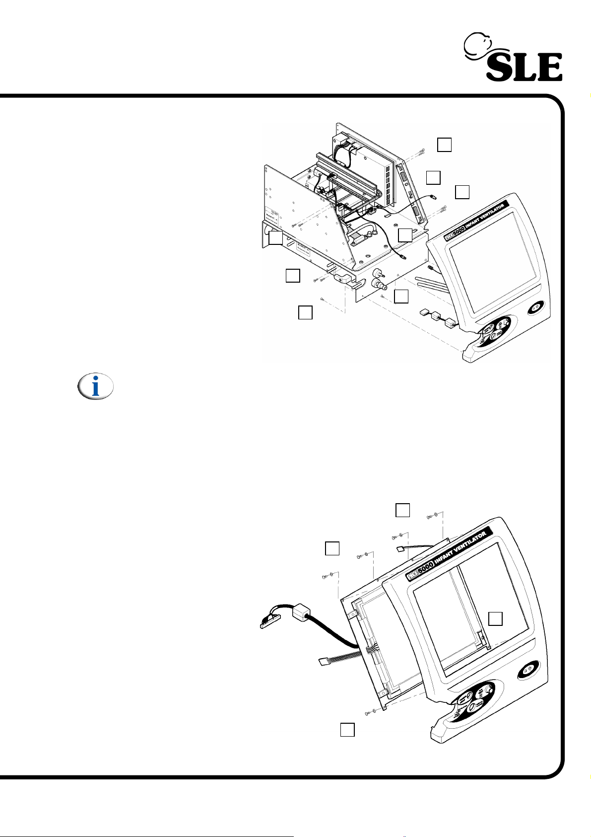
8.11.2 For ventilators 51085 to 51526
1. Remove the CAN
card as described in
section 8.1.
¦
A
2. Remove the PC
board and the monitor
control board as
described in section 8.6.
¦
3. Remove the 4 screws
(A) retaining the screen
tie bars.
4. Remove the 3
remaining facia
retaining screws (B).
5. Gently draw the front
panel assembly away
from the unit.
Note: Dispaly / touch screen cables not shown for clarity.
6. Disconnect the two backlight power leads from the inverter board
(See section 8.10 on page 44).
7. Disconnect the two tubes (C).
8. Disconnect the fan electrical connector (D).
A
A
B
¦
¦
¦
C
E
D
¦
¦
¦
A
9. Disconnect the led electrical connector (E).
10. Remove the 6 facia
retaining screws and
washers (F).
11. Remove the front
facia.
¦
F
¦
F
¦
¦
F
¦
F
¦
(Model A) Page 49
Page 50
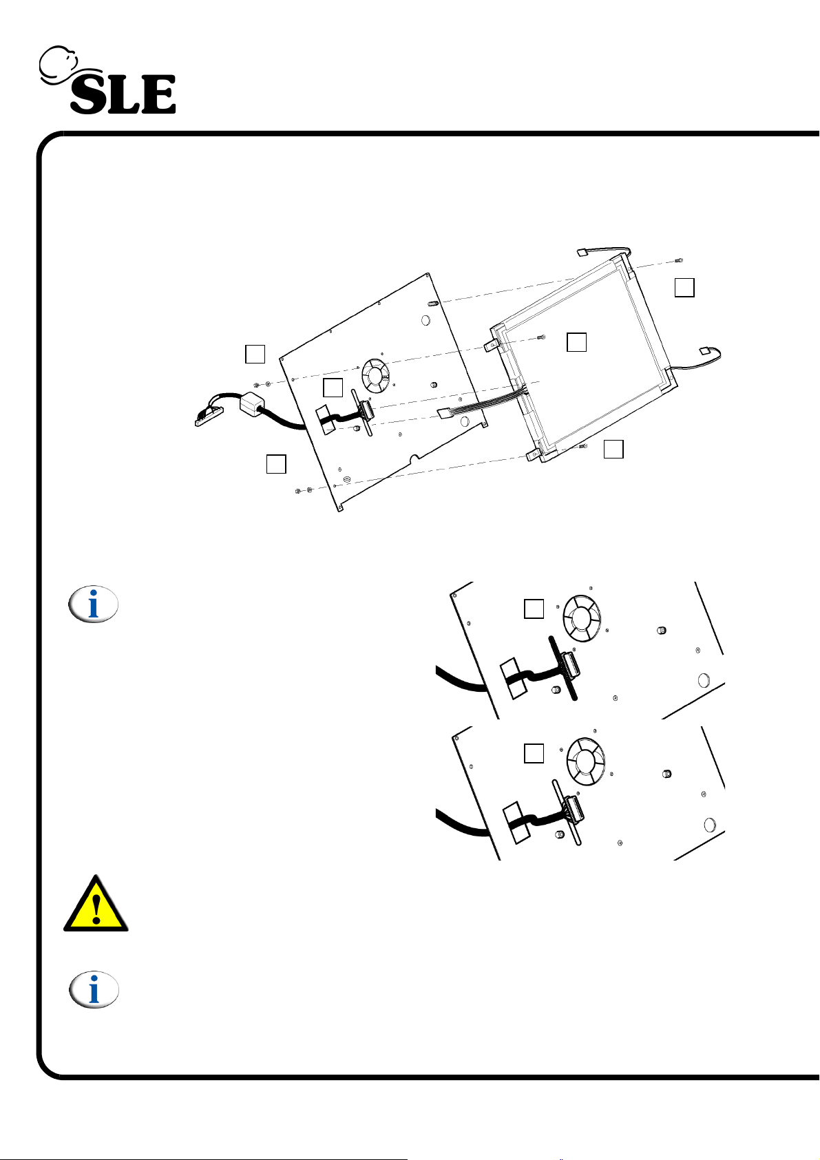
12. Remove the 2 screws (G) retaining the right hand side of the LCD / touch
screen assembly.
13. Remove the 2 nuts, washers (H) and screws (I) retaining the left hand side of
the LCD / touch screen assembly.
¦
G
¦
H
¦
J
¦
H
I
¦
I
¦
14. To free the cable, detach the locking rod (K) by cutting the adhesive, (White
locking rod only).
Note: For ventilators serial number
51085 to 51163 the connecting cable
is locked in position by a black nylon
locking rod (K) (Part Nº: T1306).
For ventilators serial number 51164
to 51569 the connecting cable is
locked in position by a white nylon
locking rod (Part Nº: T1306/01). The
locking rod is also held in postion by
a white silicone adhesive.
K
¦
K
¦
Warning:The black locking rod should not be used on ventilators 51164
onwards as it is thicker and will not allow correct assembly of the LCD/
Touch screen.
Note: For ventilators serial number 51164 onwards the LCD cable assembly
is cable tied to a pillar on the rear face of the mounting plate. Ventilators
prior to serial number 51164 may also have the LCD cable assembly cable
tie if fitted with service kit N9052.
Page 50 (Model A)
Page 51
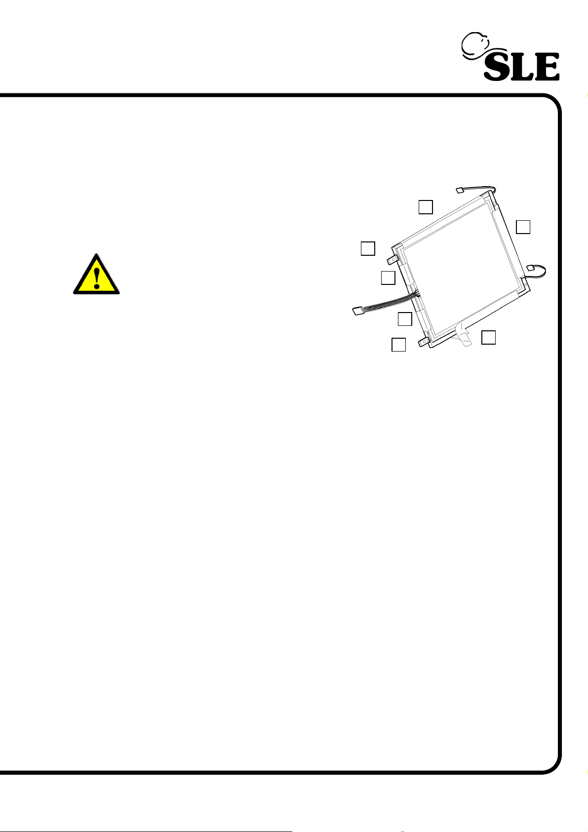
15. Separate the LCD / touch screen assembly from the mounting plate.
16. Disconnect the connecting cable (J) from the rear of the LCD assembly.
17. The LCD / touch screen assembly is now free.
18. To remove the touch screen, peel off
the adhesive tape (L).
19. Once the tape is remove the touch
screen can be removed.
Warning: Do not touch the LCD screen
with bare hands. This is to prevent
grease contamination of the surface
(i.e. finger prints).
M
¦
L
¦
L
¦
¦
L
20. With the touch screen removed the
two LCD mounting blocks (M) can be
removed as access to their fixing screws
is now possible.
21. Assembly is reversal of removal.
Setup: If the entire assembly or just the touch screen has been replaced the
screen calibration routine will have to be carried out.
M
L
¦
¦
¦
L
(Model A) Page 51
Page 52
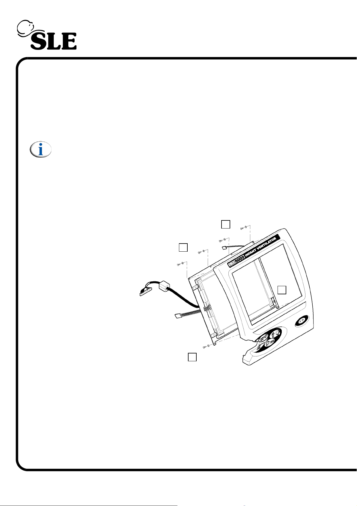
8.11.3 For ventilators 51527 to 51569
1. Remove the CAN card as described in section 8.1.
2. Remove the PC board and the monitor control board as described in section
8.6.
3. Remove the 4 screws (A) retaining the screen tie bars.
4. Remove the 3 remaining facia retaining screws (B).
5. Gently draw the front panel assembly away from the unit.
Note: Dispaly / touch screen cables not shown for clarity.
6. Disconnect the two backlight power leads from the inverter board
(See section 8.10 on page 44).
7. Disconnect the two tubes (C).
8. Disconnect the fan electrical connector (D).
9. Disconnect the led electrical connector (E).
F
10. Remove the 6 facia
retaining screws and
washers (F).
11. Remove the front
facia.
¦
¦
F
¦
¦
F
¦
¦
F
Page 52 (Model A)
Page 53
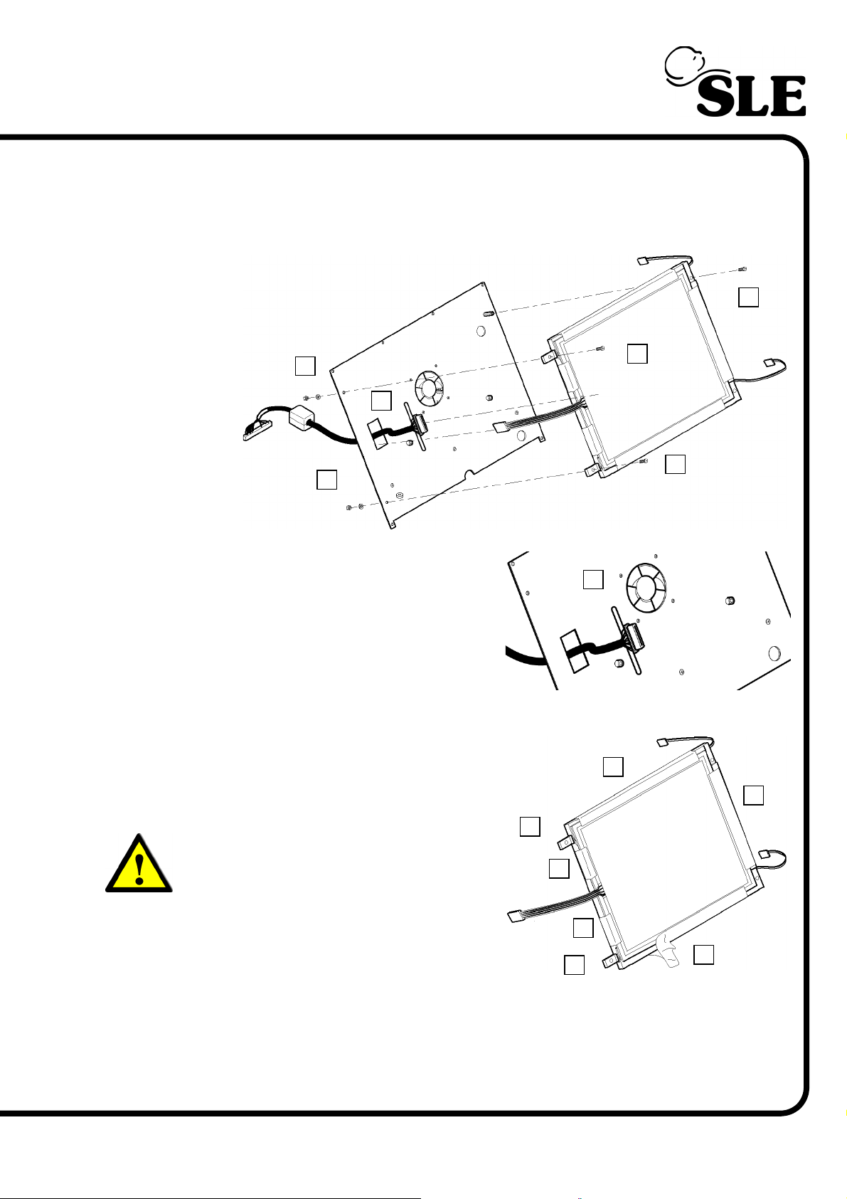
12. Remove the 2 screws (G) retaining the right hand side of the LCD / touch
screen assembly.
13. Remove the 2 nuts, washers (H) and screws (I) retaining the left hand side of
the LCD / touch screen assembly.
¦
G
¦
H
¦
J
¦
H
¦
14. To free the cable (J), detach the
locking rod (K) by cutting the adhesive.
15. Separate the LCD / touch screen
assembly from the mounting plate.
16. Disconnect the connecting cable (J)
from the rear of the LCD assembly.
17. The LCD / touch screen assembly is now free.
18. To remove the touch screen, peel off
the adhesive tape (L).
19. Once the tape is remove the touch
screen can be removed.
Warning: Do not touch the LCD screen
with bare hands. This is to prevent
grease contamination of the surface
(i.e. finger prints).
M
¦
L
K
¦
¦
I
¦
I
L
¦
¦
L
20. With the touch screen removed the
two LCD mounting blocks (M) can be
removed as access to their fixing screws
is now possible.
21. Assembly is reversal of removal.
Setup: If the entire assembly or just the touch screen has been replaced the
screen calibration routine will have to be carried out.
(Model A) Page 53
M
L
¦
¦
¦
L
Page 54
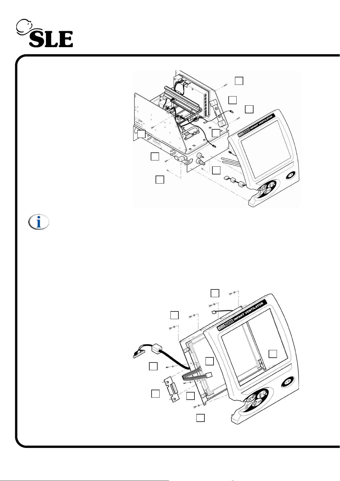
8.11.4 For ventilators 51570 onwards
1. Remove the CAN
card as described in
section 8.1.
¦
A
E
C
D
¦
¦
¦
A
2. Remove the PC
board and the monitor
control board as
described in section 8.6.
3. Remove the 4 screws
(A) retaining the screen
tie bars.
4. Remove the 3
remaining facia
retaining screws (B).
5. Gently draw the front
panel assembly away
from the unit.
Note: Dispaly / touch screen cables not shown for clarity.
6. Disconnect the two backlight power leads from the inverter board
(See section 8.10 on page 44).
7. Disconnect the two tubes (C).
8. Disconnect the fan electrical connector (D).
A
¦
¦
A
¦
¦
B
9. Disconnect the led electrical connector (E).
10. Remove the 6 facia
retaining screws and
washers (F).
11. Remove the front
facia.
12. Withdraw the touch
screen cable (G)
through the hole in the
LCD cable clamp plate
(I).
13. Remove the two
screws and washers
(H) retaining the LCD
cable clamp plate (I).
14. Slide out the LCD
retauning clamp (I).
H
I
¦
¦
¦
F
¦
H
¦
F
¦
G
¦
¦
F
¦
F
¦
Page 54 (Model A)
Page 55
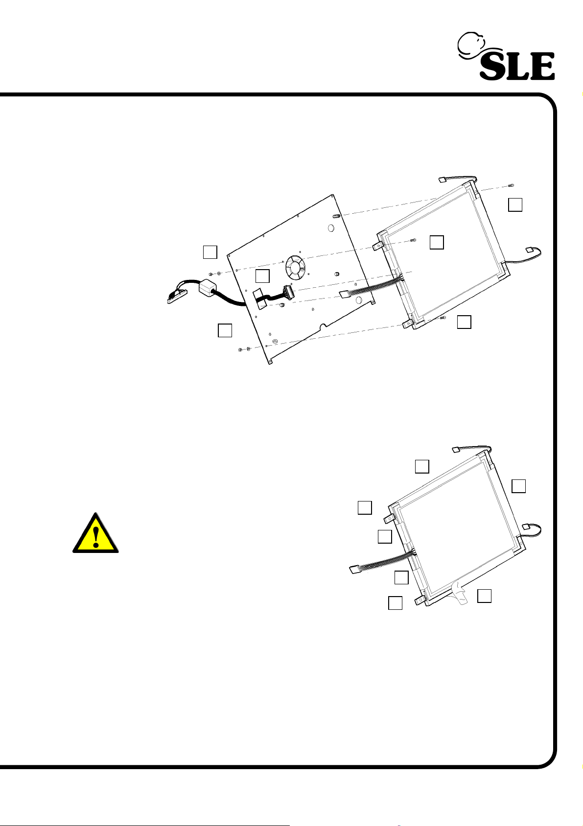
15. Remove the 2 screws (J) retaining the right hand side of the LCD / touch
screen assembly.
16. Remove the 2 nuts, washers (K) and screws (L) retaining the left hand side of
the LCD / touch screen assembly.
¦
J
¦
L
K
¦
K
M
¦
¦
L
¦
17. Separate the LCD / touch screen assembly from the mounting plate.
18. Disconnect the connecting cable (M) from the rear of the LCD assembly.
19. The LCD / touch screen assembly is now free.
20. To remove the touch screen, peel off
the adhesive tape (N).
21. Once the tape is remove the touch
screen can be removed.
Warning: Do not touch the LCD screen
with bare hands. This is to prevent
grease contamination of the surface
(i.e. finger prints).
O
¦
N
¦
N
¦
¦
N
22. With the touch screen removed the
two LCD mounting blocks (O) can be
removed as access to their fixing screws
is now possible.
23. Assembly is reversal of removal.
Setup: If the entire assembly or just the touch screen has been replaced the
screen calibration routine will have to be carried out.
(Model A) Page 55
O
N
¦
¦
¦
N
Page 56
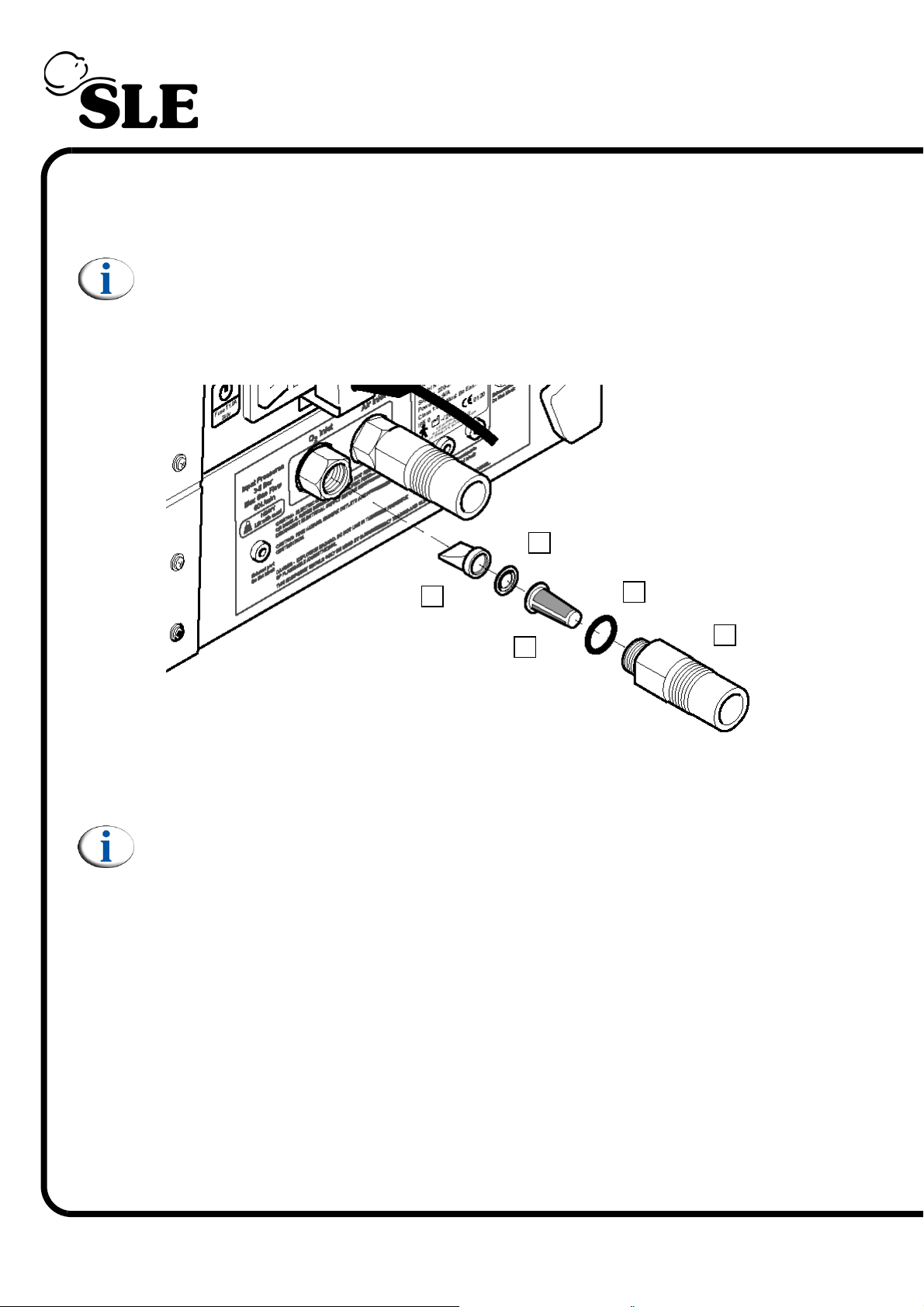
9. Component Replacement (Pneumatic unit)
9.1 N2185/05 & 06 Duckbill and conical filters.
Note: The O2 inlet connector is used to illustrate the process, the procedure
is the same for the Air inlet connector.
1. Using a spanner remove the inlet connector (A).
¦
¦
E
C
D
¦
¦
B
¦
A
2. Remove O-ring (B), Nylon filter cone (C), Washer (D) and Duckbill check valve
(E).
3. Assembly is reversal of removal.
Note: The O-ring (B) should always be replaced with a new item.
Setup: No setup is required for this device.
Page 56 (Model A)
Page 57
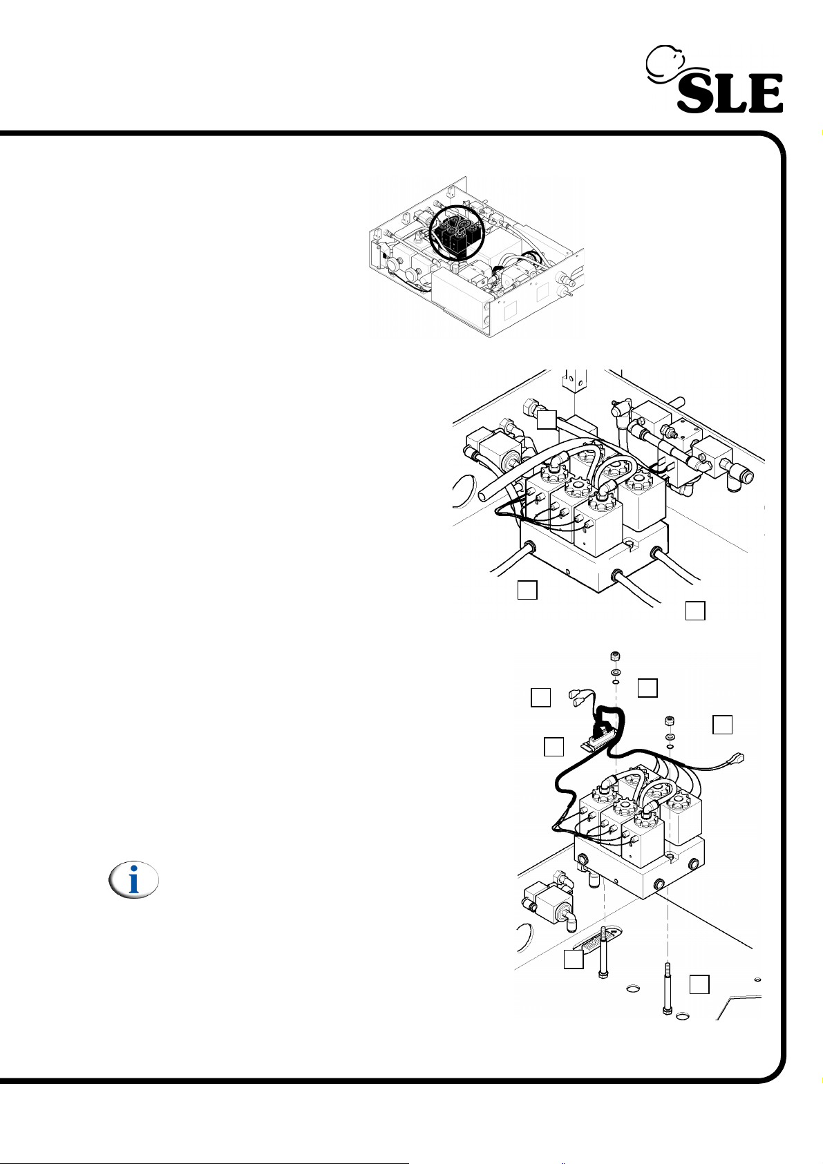
9.2 L0287 Blender Assembly
Location in pneumatic
unit.
1. Disconnect the two mixing
chamber tubes (A).
2. Disconnect the PR1 tube (B).
3. Disconnect the PR2 tube (C).
4. Disconnect the electrical connectors from
SV8 (D).
5. Disconnect the electrical connectors from
SV7 (E).
6. Disconnect the blender loom connector
from the bulk head (F).
7. Remove the two shake proof nuts,
washers and O-rings (G).
¦
B
D
C
¦
F
¦
¦
¦
G
¦
¦
¦
A
E
¦
The blender can now be removed.
Note: Ensure that the rubber sleeves (H)
remain on the blender support studs.
8. Assembly is reversal of removal.
Setup: A full system calibration is required
for this component.
(Model A) Page 57
H
¦
¦
H
Page 58
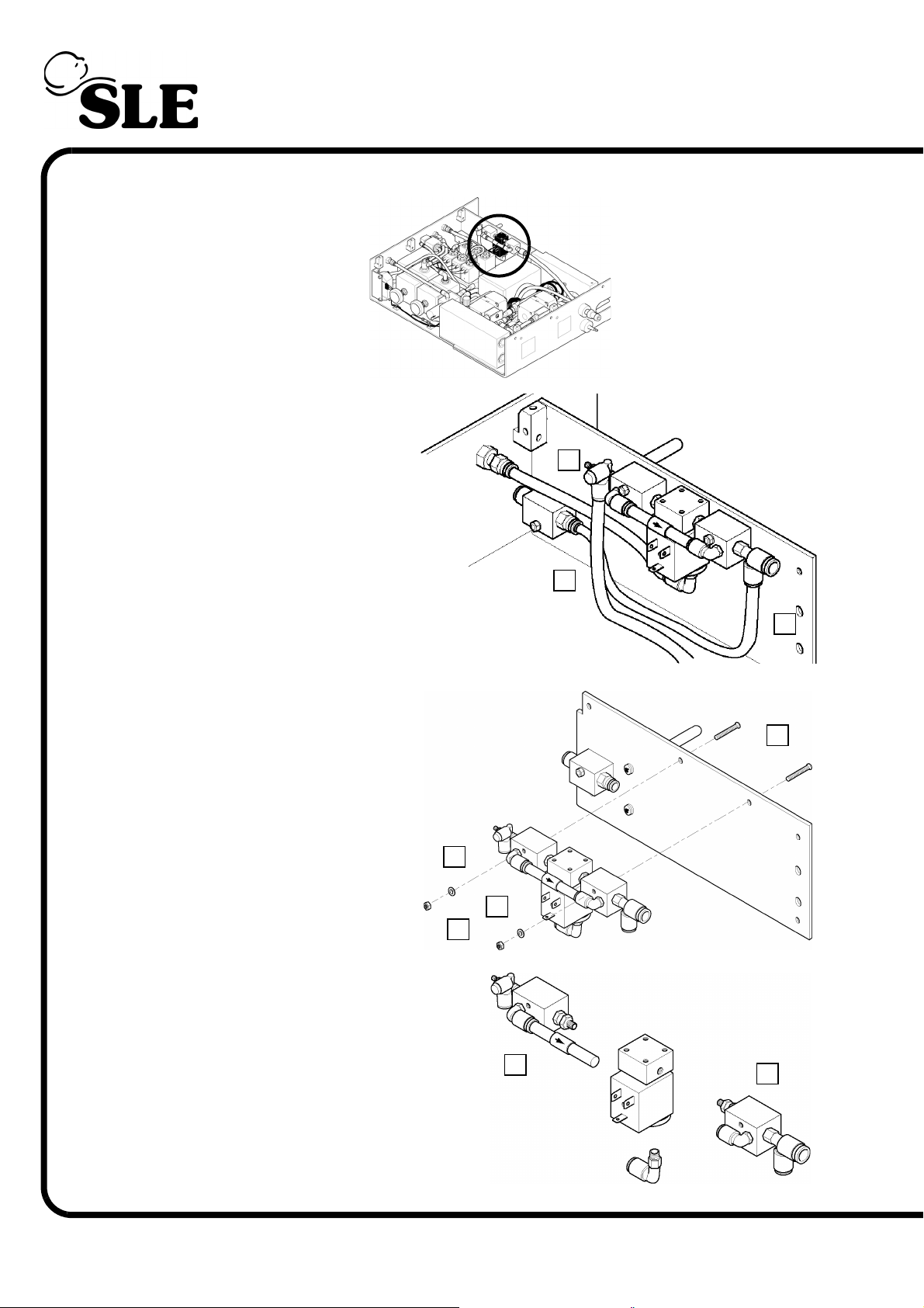
9.3 N2195/06 Fresh Gas Supply solenoid (SV7)
Location in pneumatic
unit.
1. Disconnect the FR1 to
mixing chamber tube (A).
2. Disconnect the SV7 to PRV1
tube (B).
3. Disconnect the SV7 to
overboard dump tube (C).
4. Remove the two screws (D),
nuts (E) and washers (F)
securing the SV7 solenoid
assembly to the bulkhead.
F
¦
¦
E
F
¦
¦
A
C
¦
¦
B
¦
D
¦
5. Detach the SV7 solenoid valve from
the two bypass mounting block
assemblies (G) and (H) as shown.
¦
6. Assembly is reversal of removal.
Setup: The pneumatic setup procedure
is required for this component.
Page 58 (Model A)
G
H
¦
Page 59
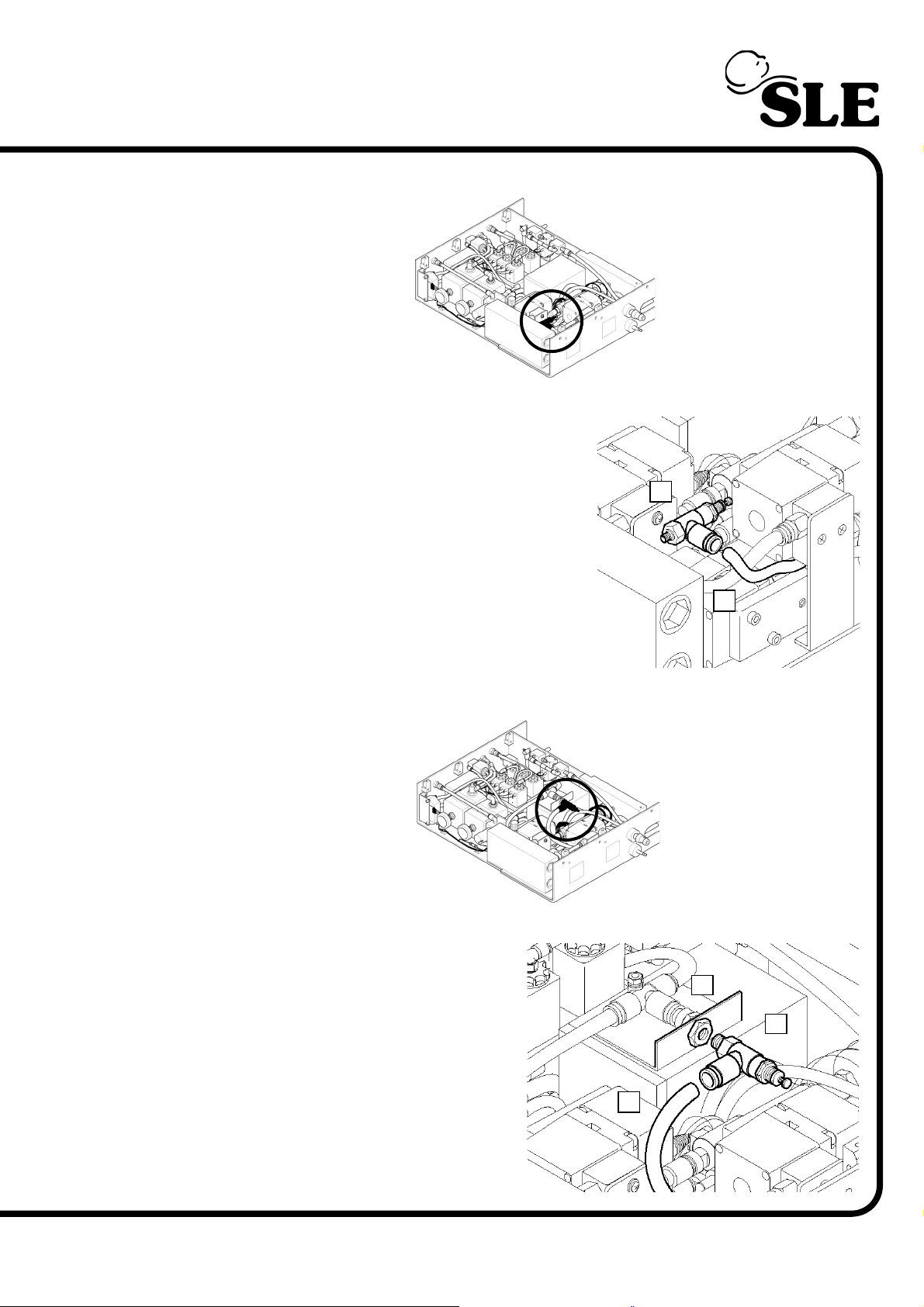
9.4 N6612 Purge Regulator (PR7) Pre PAM (Proximal Airway Modification)
Location in pneumatic
unit.
1. Remove the outlet hose (A).
2. Remove the purge regulator (B) using a
spanner to undo the base nut.
3. Assembly is reversal of removal.
B
¦
Setup: The pneumatic setup procedure is
required for this component.
¦
A
9.5 N6612 Purge Regulator (PR7) Post PAM (Proximal Airway Modification)
Location in pneumatic
unit.
1. Remove the outlet hose (A).
2. Remove the purge regulator (B)
using a spanner to undo the base nut.
Take care not to loosen the bulkhead
flitting (C).
3. Assembly is reversal of removal.
A
Setup: The pneumatic setup
procedure is required for this
component.
¦
C
¦
¦
B
(Model A) Page 59
Page 60
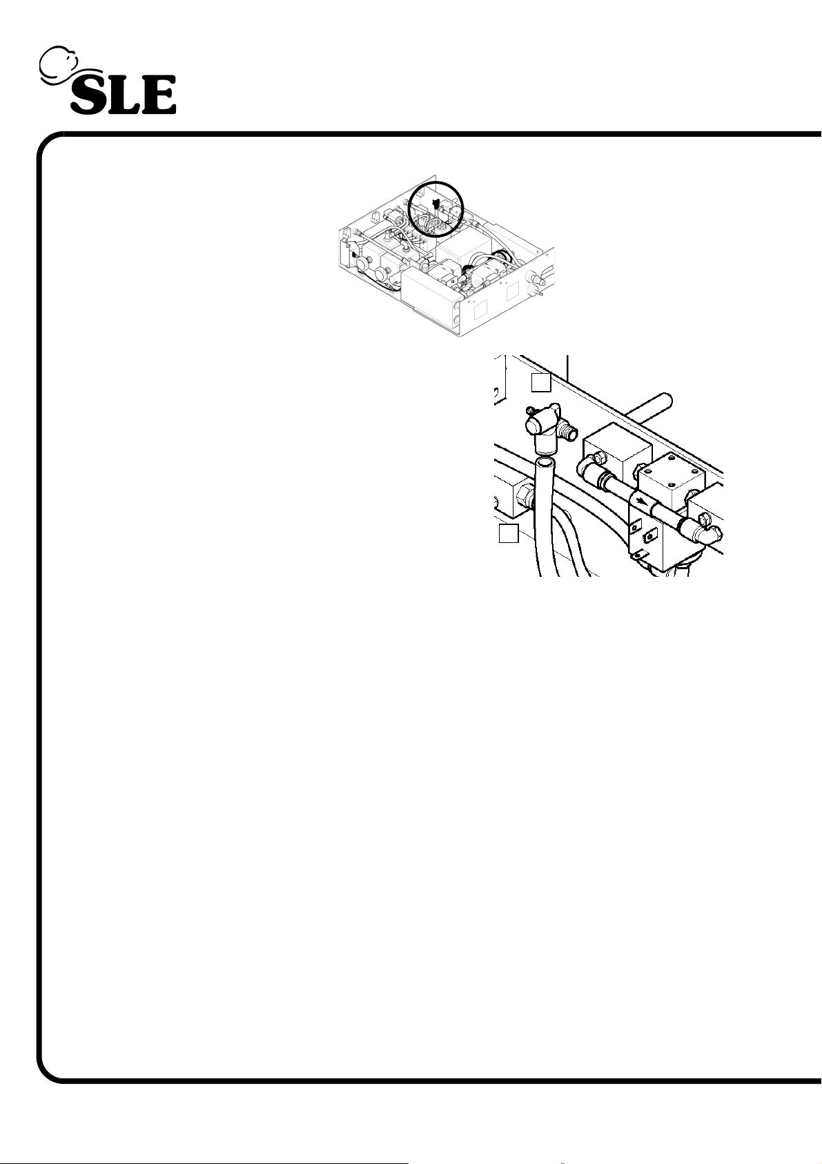
9.6 N6614 Speed controller (FR1)
Location in pneumatic unit.
1. Remove the outlet hose (A).
2. Remove the Speed controller (B) using a
spanner to undo the base nut.
3. Assembly is reversal of removal.
Setup: The pneumatic setup procedure is
required for this component.
A
B
¦
¦
Page 60 (Model A)
Page 61
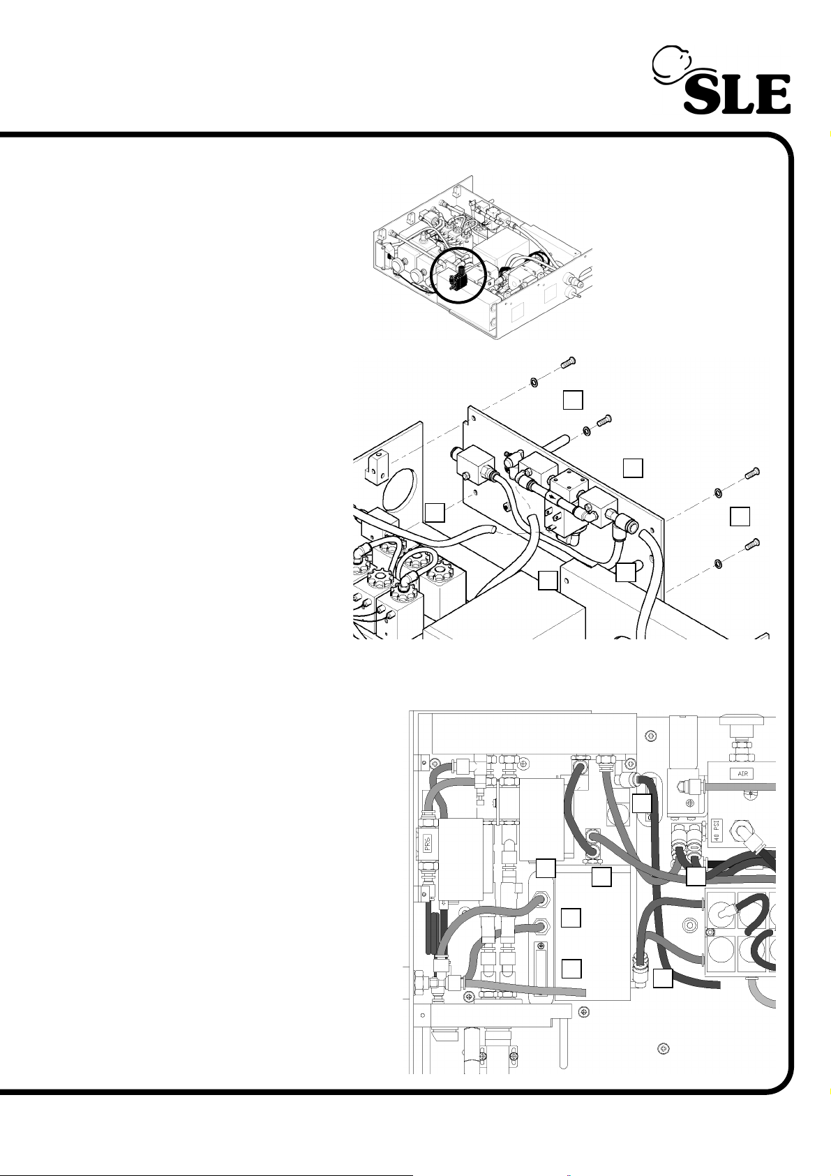
9.7 N6613 Purge Regulator (PR5) Pre Proximal Airway Modification
Location in pneumatic
unit.
¦
C
F
¦
A
¦
¦
E
¦
J
1. Remove the four
screws and washers
(A) retaining the
partition assembly (B).
2. Gently release the
assembly so access
the tubing.
3. Disconnect the tube
connected to FR1 (C).
4. Disconnect the tube
connected to SV7 (D).
5. Disconnect the
fresh gas tube
connected to the SV7 bypass mounting block (E).
6. Remove the partition assembly (B) from the pneumatic unit.
7. Disconnect the following
tubes.
Fresh gas monitoring tube
(F).
Proximal airway monitoring
tube (G).
Blender port 3 to mixing
chamber tube (H).
D
¦
¦
Blender port 4 to mixing
chamber tube (I).
¦
G
B
K
¦
¦
A
¦
¦
H
¦
Mixing chamber to SV8 tube
(J).
Manifold to air regulator tube
(K).
8. Disconnect the electrical
loom connector (L).
(Model A) Page 61
¦
¦
L
I
Page 62
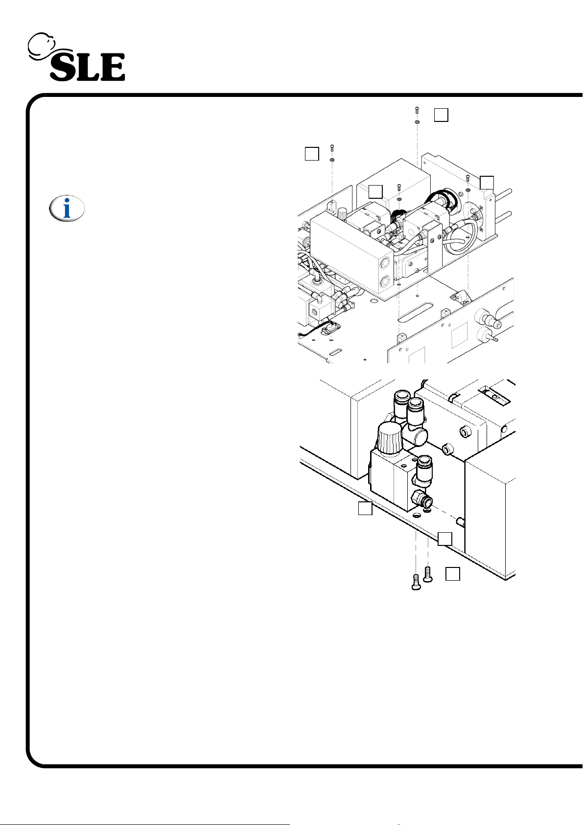
9. Remove the four screws and
washers (M) retaining the HFO
module.
10. Remove the module from the
pneumatic unit.
Note: The fresh gas and proximal
airway tube fittings impede the
removal of the module.
11. Remove the two screws (N).
M
¦
M
¦
M
¦
M
¦
12. Slide the purge regulator PR5 (O)
off the manifold fitting (P).
13. Assembly is reversal of removal.
Setup: The pneumatic setup
procedure is required for this
component.
O
¦
¦
P
¦
N
¦
¦
Page 62 (Model A)
Page 63
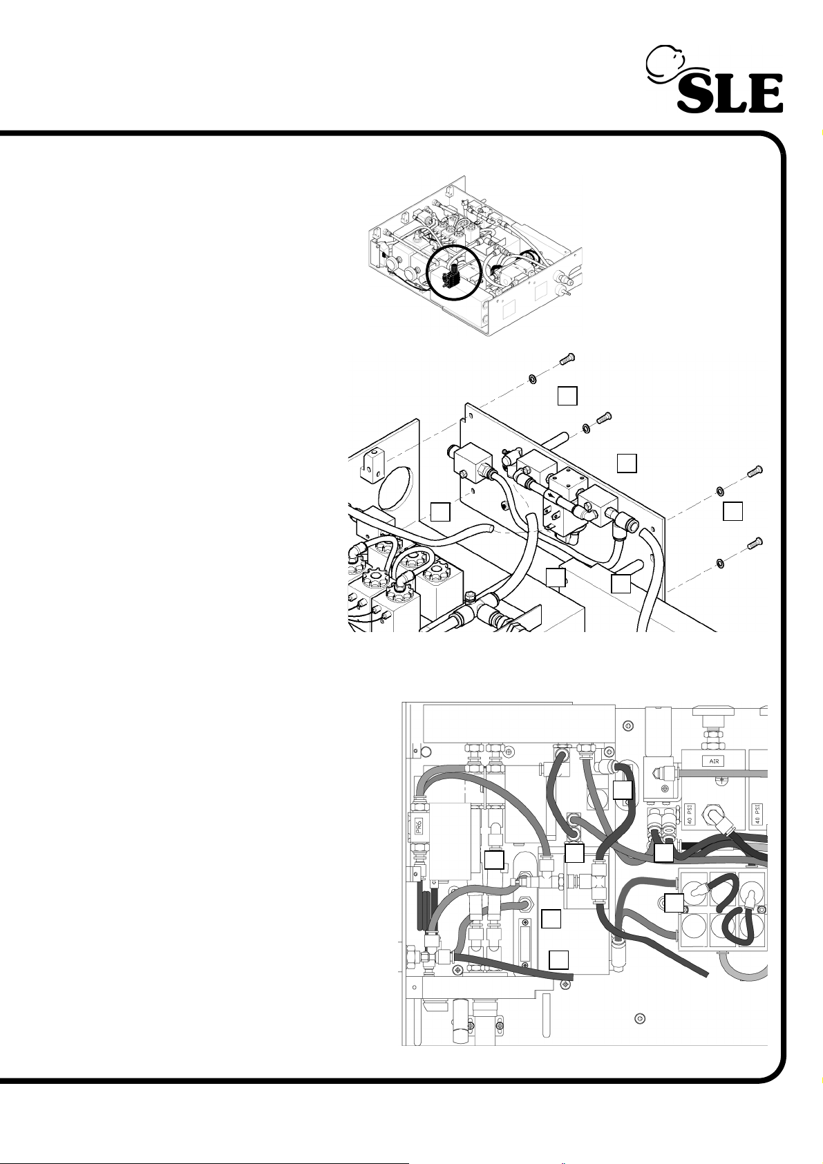
9.8 N6613 or /03 Purge Regulator (PR5) Post Proximal Airway Modification
Location in pneumatic
unit.
¦
¦
G
¦
¦
C
L
A
¦
J
¦
¦
¦
E
K
1. Remove the four
screws and washers
(A) retaining the
partition assembly (B).
2. Gently release the
assembly so access
the tubing.
3. Disconnect the tube
connected to FR1 (C).
4. Disconnect the tube
connected to SV7 (D).
5. Disconnect the
fresh gas tube
connected to the SV7 bypass mounting block (E).
6. Remove the partition assembly (B) from the pneumatic unit.
7. Disconnect the following
tubes.
Fresh gas monitoring tube
(F).
Proximal airway monitoring
tube (G).
Blender port 3 to mixing
chamber tube (H).
Blender port 4 to mixing
chamber tube (I).
Mixing chamber to SV8 tube
(J).
D
¦
F
¦
B
¦
H
¦
¦
¦
A
¦
I
Manifold to air regulator tube
(K).
8. Disconnect the electrical
loom connector (L).
(Model A) Page 63
Page 64
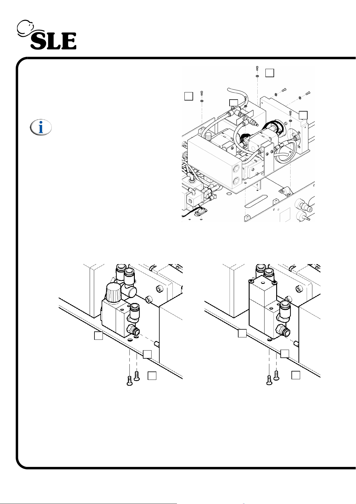
9. Remove the four screws and
washers (M) retaining the HFO
module.
10. Remove the module from the
pneumatic unit.
Note: The fresh gas and proximal
airway tube fittings impede the
removal of the module.
11. Remove the two screws (N).
M
¦
M
¦
¦
M
¦
M
12. Slide the purge regulator PR5 (O) off the manifold fitting (P).
¦
O
¦
P
¦
¦
O
¦
N
N6613
13. Assembly is reversal of removal.
N6613/03
¦
¦
P
¦
N
Setup: The pneumatic setup procedure is required for this component.
Page 64 (Model A)
Page 65
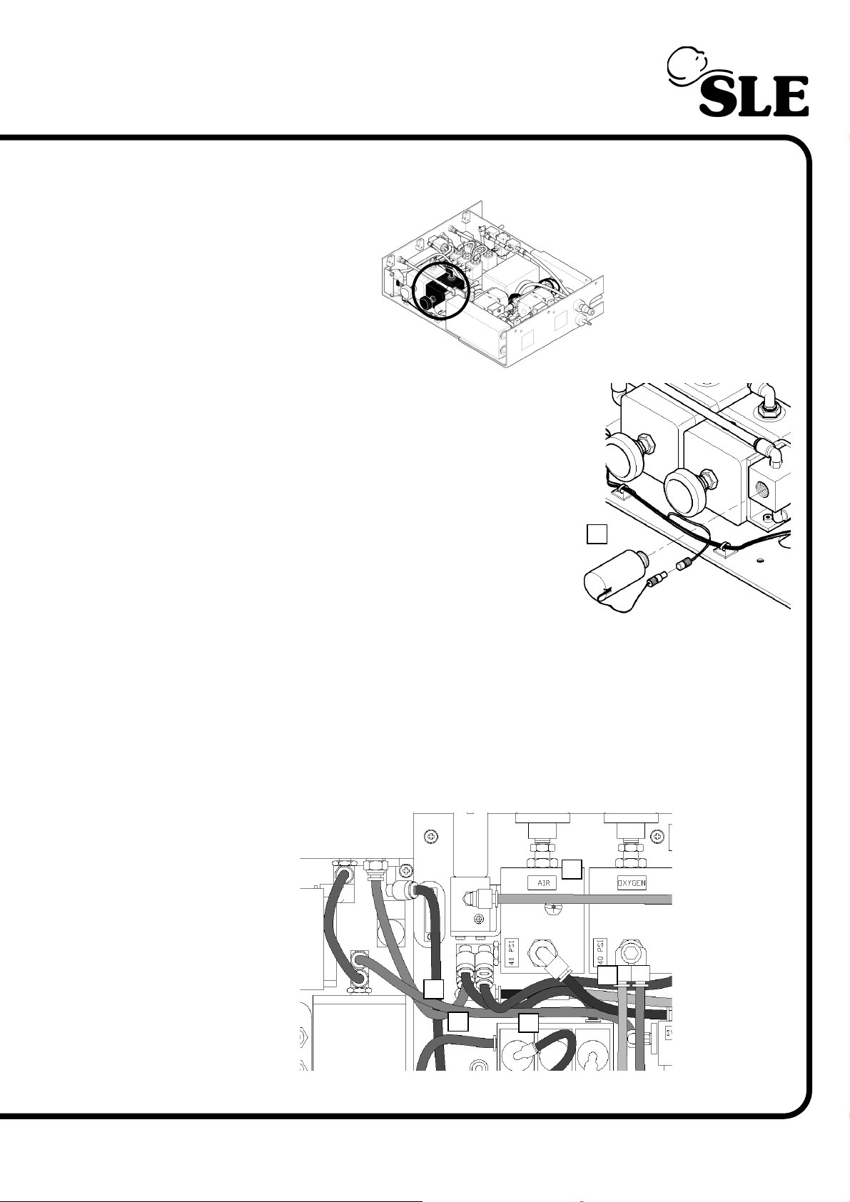
9.9 N6615/01 Input Air Regulator (PR1)
Location in pneumatic
unit.
1. Remove the Oxygen cell.
A
¦
2. Disconnect the following tubes.
Oxygen cell to overboard dump (B).
Air inlet to 40PSI air regulator (C).
40PSI air regulator to differential pressure transducer (D).
40PSI air regulator to blender port 1 (E).
40PSI air regulator to manifold (F).
B
¦
C
F
¦
E
¦
¦
D
¦
(Model A) Page 65
Page 66
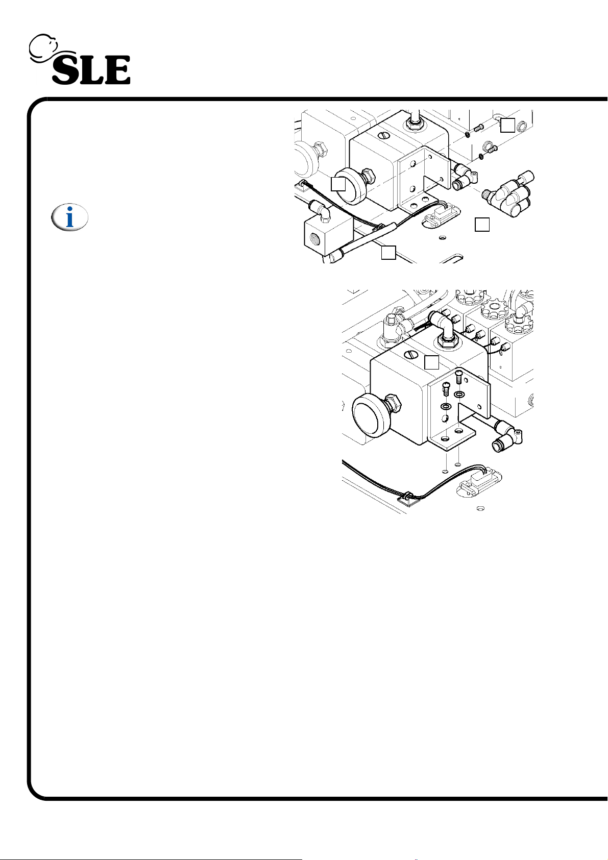
3. Using a spanner remove the
pneumatic fitting (G).
4. Remove the two screws and
washers (H) to release the Oxygen
cell manifold (I).
Note: The Oxygen cell manifold
should be removed with the tube
(J) attached.
5. Remove the two screws and washers
(K).
6. The 40PSI air regulator can now be
removed from the Pneumatic unit.
I
¦
¦
J
¦
G
H
¦
7. Assembly is reversal of removal.
Setup: The pneumatic setup procedure is
required for this component.
K
¦
Page 66 (Model A)
Page 67
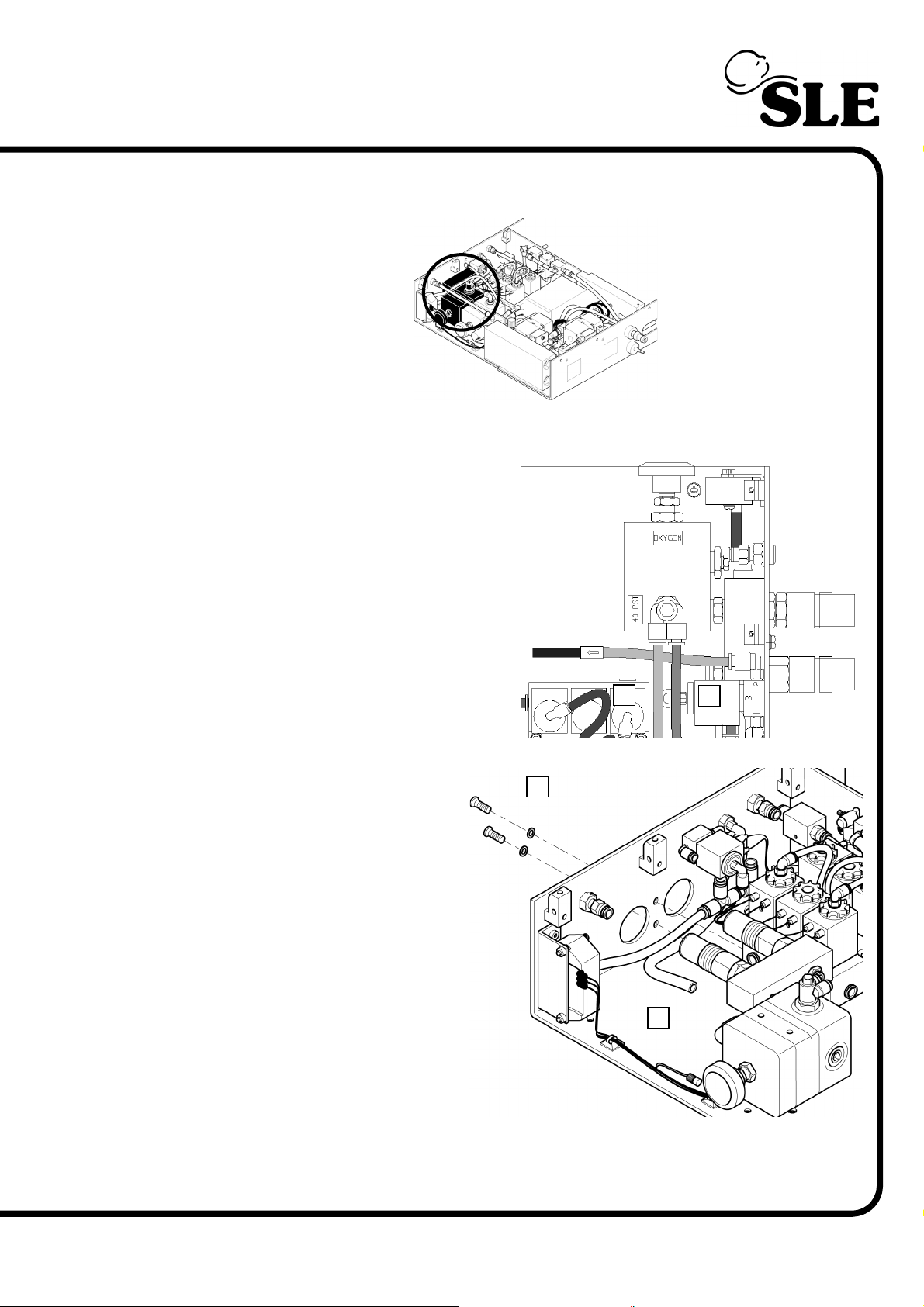
9.10 N6615/02 Input Oxygen Regulator (PR2)
Location in pneumatic
unit.
1. Remove the 40PSI air regulator as described on page 65.
2. Disconnect the following tubes.
40PSI oxygen regulator to SV8 (A).
40PSI oxygen regulator to blender O2
inlet (B).
3. Remove the two fixing screws
and washers (C).
4. Withdraw the 40PSI oxygen
regulator so that the inlet
connectors are clear of the
chassis. Disconnect the tube
(D).
5. The 40PSI oxygen regulator
can now be removed from the
Pneumatic unit.
6. Assembly is reversal of
removal.
Setup: The pneumatic setup
procedure is required for this
component.
¦
C
B
¦
D
¦
A
¦
(Model A) Page 67
Page 68
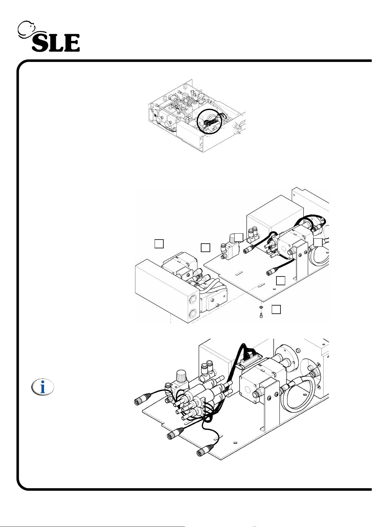
9.11 N6624 High Speed Jet Valves (SV9/10/11/12)
Location in pneumatic
unit.
1. Remove the HFO module as described in section 8.7 on page 61
2. Remove the two
screws and washers
(A) that retains the
manifold to the base
plate (B).
¦
3. Slide the
assembly (C) so as
to disengage the jet
valves from the
pneumatic
connectors.
4. Unscrew the
electrical connectors
(D, E & F) from the
pressure regulators.
5. Withdraw the jet
valve assembly from
the pneumatic
connectors
Note: The jet valves
are independent
and are only
connected together
via the loom.
C
¦
B
¦
D
F
¦
¦
E
¦
A
6. Assembly is
reversal of removal.
Setup: A full system calibration is required for this component.
Page 68 (Model A)
Page 69
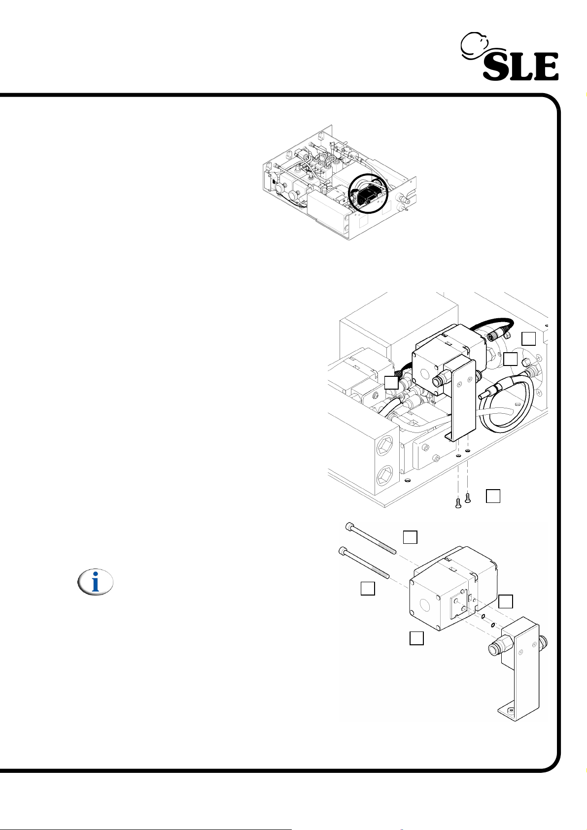
9.12 N6623, N6623/33 or N6623/S38 Pressure regulators (PR6)
Location in pneumatic
unit.
1. Remove the HFO module as described in section 9.7 on page 61
2. Unscrew the electrical connector
(A) from the pressure regulator PR6.
3. Disconnect the tubes (B & C) from
the pressure regulator manifold block.
4. Remove the two countersunk
screws (D) that retain the PR6
regulator assembly bracket to the
base plate.
C
¦
¦
A
B
¦
5. Remove the two allen cap screws (E)
that retain the PR6 pressure regulator
(F) to the manifold.
Note: On removing the regulator the
two O-ring’s (G) are freed. These Oring’s must be replaced each time
that the assembly is dismantled.
E
¦
¦
¦
D
E
G
¦
¦
F
(Model A) Page 69
Page 70
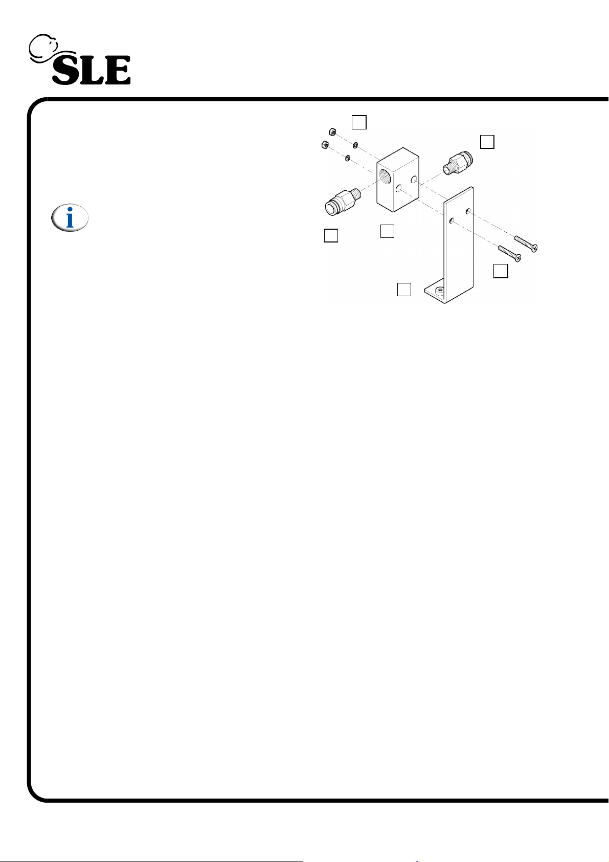
6. Remove the two countersunk screws
(H) washers and nuts (I) that retain the
manifold (J) to the bracket (K).
7. Remove the pneumatic tube
connectors (L & M).
¦
I
L
¦
Note: The PR6 pressure regulator is
made up of the following
components, pressure regulator (F),
allen cap screws (E), O-rings (G) and
manifold (J).
8. Assembly is reversal of removal.
Setup: A full system calibration is required for this component.
¦
M
¦
J
K
¦
¦
H
Page 70 (Model A)
Page 71
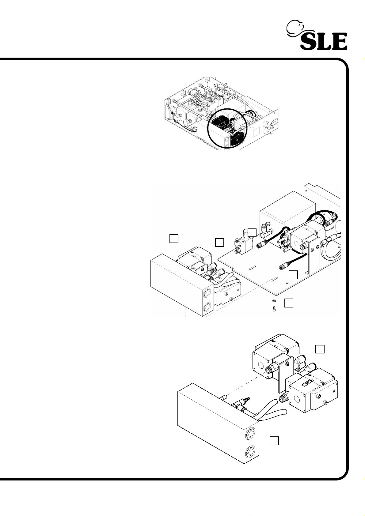
9.13 N6623, N6623/33 or N6623/S38 Pressure regulators (PR3 &PR4)
Location in pneumatic
unit.
1. Remove the HFO module as described in section 9.7 on page 61.
2. Remove the two
screws and washers
(A) that retains the
manifold to the base
plate (B).
3. Slide the
assembly (C) so as
to disengage the jet
valves from the
pneumatic
connectors.
4. Unscrew the
electrical connectors
(D & E) from the
pressure regulators.
5. Separate the pressure
regulator assembly (F) from
the manifold (G).
C
¦
B
¦
D
¦
¦
¦
E
A
¦
F
¦
G
(Model A) Page 71
Page 72
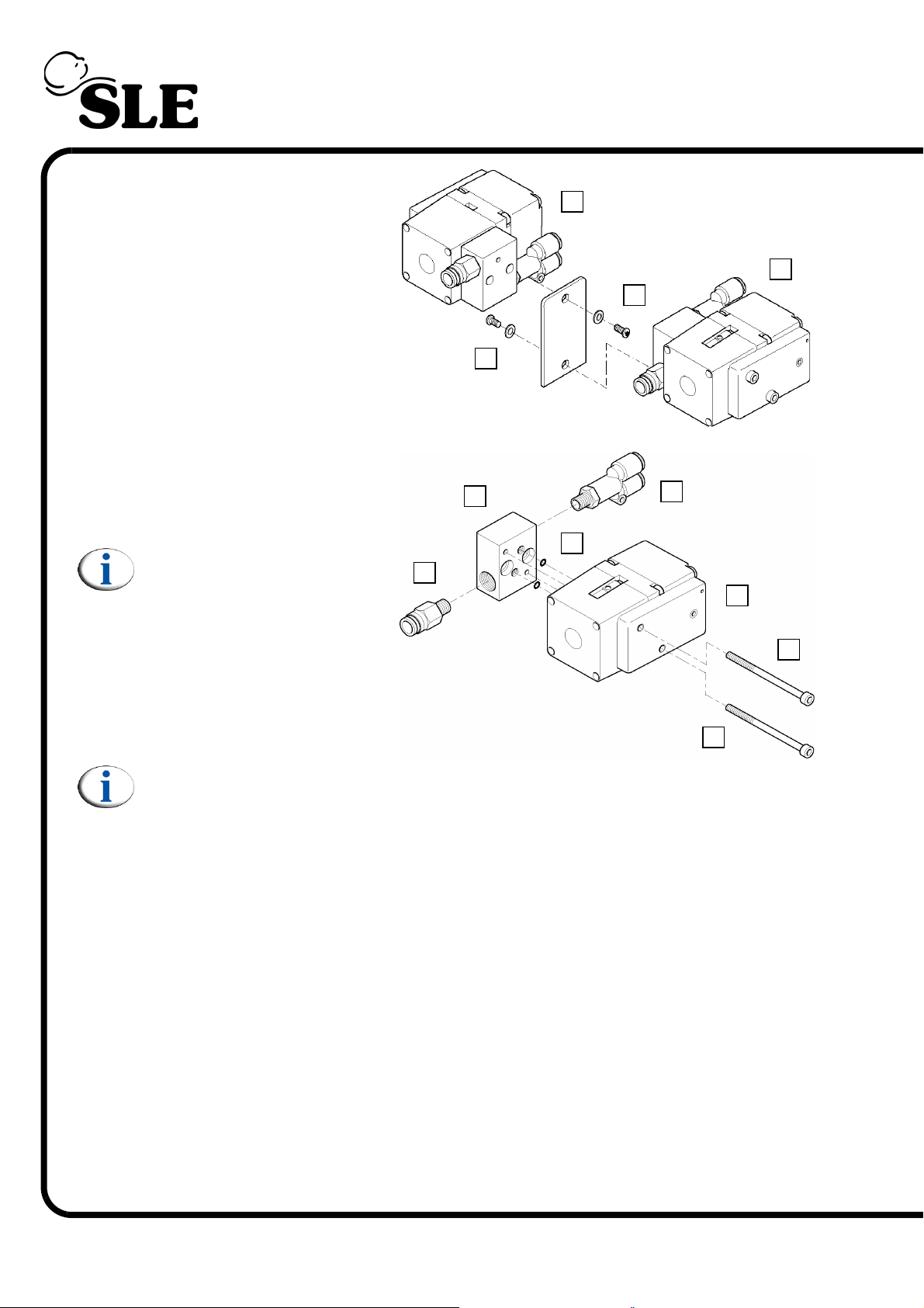
6. Remove the screw and
washer (H) that retains the
pressure regulator PR3 (I).
7. Remove the screw and
washer (J) that retains the
pressure regulator PR4 (K).
¦
I
K
H
¦
¦
¦
J
8. Remove the two allen cap
screws (L) that retain the
PR4 pressure regulator (K)
to the manifold (M).
Note: On removing the
regulator the two O-ring’s
(N) are freed. These Oring’s must be replaced
each time that the
assembly is dismantled.
9. Remove the pneumatic
tube connectors (O & P).
Note: The procedure is the same for the PR3 pressure regulator.
10. Assembly is reversal of removal.
Setup: A full system calibration is required for this component.
P
¦
M
¦
¦
N
¦
O
¦
L
K
¦
¦
L
Page 72 (Model A)
Page 73
A0763/02 Board
(Model A) Page 73
Page 74
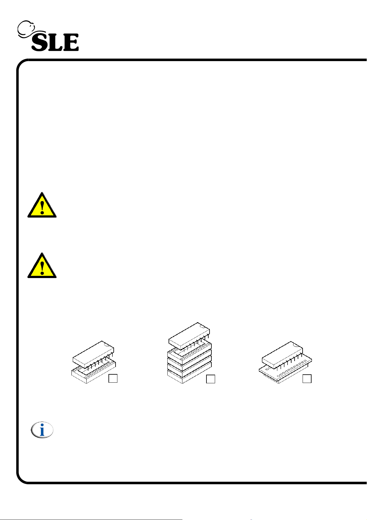
10. A0763/02 Monitor and control board
The SLE5000 has two revisions of the base A0760 PCB that make up the A0763/
02 board, A0760 Rev D & A0760 Rev E.
The differences between the REV D board and Rev E A0760 base PCB are new
tracks. These are to remove the need for the L0273 adaptor stack and the J0764/
A adaptor board.
When replacing the A0763/02 confirm the following:
If the replacement board is marked as A0760 Rev D this requires either the
L0273 adaptor stack and the J0764/A adaptor board for IC’s mounted at U23 &
U33.
Warning: For Rev D A0760 base PCB’s fitting the IC’s to U23 & U33 directly
will cause them to fail on power up. L0273 adaptor stack or the J0764/A
adaptor board must be used.
If the replacement board is marked as A0760 Rev E the IC’s mounted at U23 &
U33 are fitted directly to the board mounted sockets.
Warning: For Rev E A0760 base PCB’s fitting the L0273 adaptor stack or the
J0764/A adaptor board will cause U23 & U33 to fail on power up.
10.1 U23 and U33 socket configurations for A0760 Rev D base PCB.
The IC mounted at U23 and U33 can be connected to the A0763/02 board with in
3 ways.
A
A) direct
B) Via a 28way adaptor socket SLE part Nº: L0273
C) Via the adaptor board SLE part Nº: J0764/A
Note For REV D boards only: IC’s mounted directly to the A0763/02 board
(A) are Electrically Erasable Programmable Read Only Memory. IC’s
mounted via L0273 or J0764/A are UV Erasable Programmable Read Only
Memory.
B
C
Page 74 (Model A)
Page 75
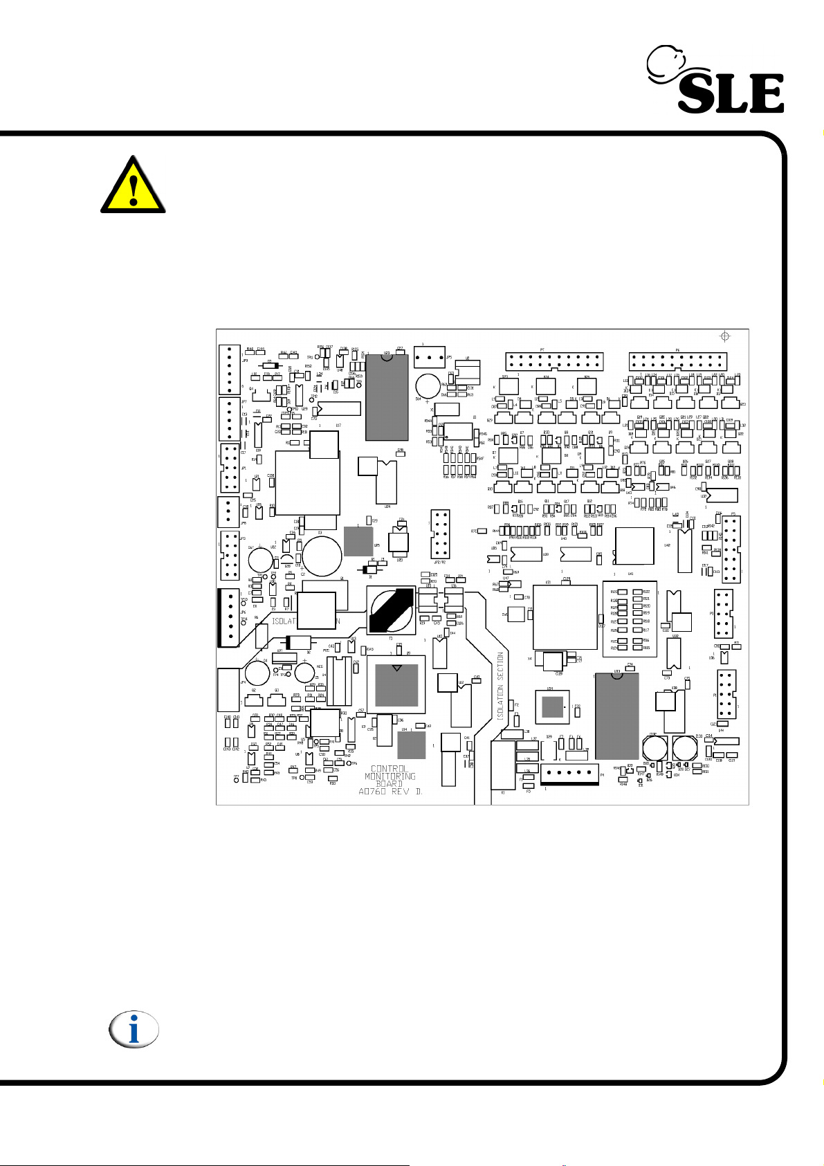
Warning: IC’s mounted directly to the U23 and 33 cannot be used with either
adaptor. IC’s mounted via the adaptors cannot be connected directly to the
board. Connection of the devices incorrectly will cause them to fail.
10.2 A0763/02 board progammable devices
The A0763/02 board is divided into two sections a) the monitor side and b) the
control side.The monitor section is divided into a further two sections c) monitor
isolated and d) monitor non islolated.
d
¦
1
¦
2
a
¦
3
c
On the A0763/02 board there are six programmable devices. These devices are:
¦
4
6
¦
b
¦
e
¦
5
1) U23 monitor software non isolated IC
2) U25 monitor non isolated PAL
3) U9 monitor software isolated IC
4) U14 monitor isolated PAL
5) U33 controller software IC
6) U34 controller PAL
Note: On early versions of the A0763/02 board some of the PAL devices are
soldered to the board rather than socketed.
(Model A) Page 75
Page 76
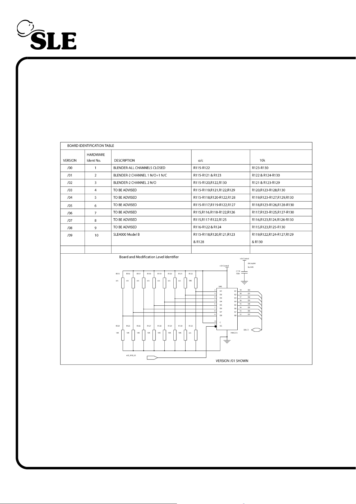
10.3 A0763/02 Board Hardware Identifier
The A0763/02 board has a group of resistors that allow the software to recognise
the pneumatic unit configuration. There are 9 hardware idents possible on the
board.
The table below outlines the resistor groups to produce specific hardware ID’s.
The SLE4000 model A and SLE5000 model A use Hardware Ident 3.
Page 76 (Model A)
Page 77
Electrical Safety Testing
(Model A) Page 77
Page 78

This page is intentionally blank.
Page 78 (Model A)
Page 79
11. Electrical Safety Testing of the SLE5000
This test is performed using an approved electrical safety testing device.
The electrical safety test must be carried out on the unit with all the electrical connections
intact.
Ensure the mains switch on the ventilator is ON for the duration of these tests.
Equipment under test is : SLE5000 Infant Ventilator Class 1B (flow sensor is a Floating type
applied part)
Test Expected Results
Class B Tests
Mains Voltage 240V 240V
Expected Value Tolerance
Insulation Resistance
Earth Continuity
Earth Leakage
Earth Leakage (supply o/c)
Enclosure Leakage (normal)
Enclosure Leakage (earth o/c)
Enclosure Leakage (supply o/c)
Patient Leakage on Applied Part
Patient Leakage on Applied Part (Earth o/c)
Patient Leakage on Applied Part (supply o/c)
Class BF Tests
Mains on Applied Part Normal
Mains on Applied Part Reversed
Check that in all the preceding tests:
>200MΩ
<0.2Ω
0 μA +150 μA
0 μA +150 μA
0 μA +150 μA
0 μA +150 μA
0 μA +150 μA
0 μA +150 μA
0 μA +150 μA
0 μA +150 μA
0 μA +150 μA
0 μA +150 μA
Check the resistance to earth on the internal metal screening is less than 0.2Ω.
(Model A) Page 79
Page 80

This page is intentionally blank.
Page 80 (Model A)
Page 81
PSU Testing
(Model A) Page 81
Page 82

This page is intentionally blank.
Page 82 (Model A)
Page 83
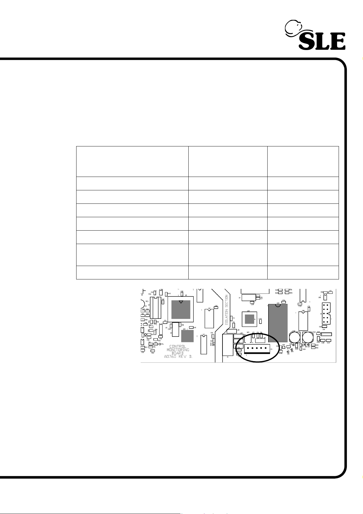
12. PSU Testing.
This check should only be carried out if the PSU is suspected to be faulty.
a) Unplug the battery connector from the PSU.
b) Remove the PC Board
c) Turn on the ventilator and check the output voltages of the power supply at the
following points on the wireloom.
On P4 (connection to the controller
side of the controller monitor board)
check the following pins.;
Voltag e
Lower Limit
Voltage
Upper Limit
PL4/1 22.8V 25.2V
PL4/2 11.4V 12.6V
PL4/3 4.875V 5.325V
PL4/4 4.875V 5.325V
PL4/5 GND (digital) GND (digital)
PL4/6 GND (high power,
solenoid return)
GND (high power,
solenoid return)
Battery connector voltage 13.8V 14.2V
Location of P4
d) Turn off the ventilator and reconnect the battery connector.
e) Refit the PC board
f) Turn on the ventilator and check that the cooling fan and the two fans within
the PSU are rotating and the power LED on the front panel is illuminated
(requires control/monitor pcb plugged in).
g) On the battery connection, check that the voltage indicates battery charging.
Look for the voltage increasing gradually as the battery charges. 13.8V = o/c
condition or battery fully charged.
(Model A) Page 83
Page 84

This page is intentionally blank.
Page 84 (Model A)
Page 85
Maintenance and Overhaul
(Model A) Page 85
Page 86

13. Maintenance and Overhaul
The ventilator has the following maintenance / overhaul schedule.
6 months Preventative maintenance Kit: N9010/06
12 months Preventative maintenance Kit: N9010/12
18 months Preventative maintenance Kit: N9010/06
24 months (10,000hrs) Overhaul Kit: N9010/24
30 months Preventative maintenance Kit: N9010/06
36 months Preventative maintenance Kit: N9010/12
42 months Preventative maintenance Kit: N9010/06
48 months (20,000hrs) Overhaul Kit: N9010/48
13.1 Preventative Maintenance
Their are two types of preventative maintenance kit available, the N9010/06 (six month kit)
and the N9010/12 (twelve month kit).
The N9010/06 contains the following:
Conical filter Qty 2 Part Nº: N2185/06
Duckbill valve Qty 2 Part Nº: N2185/05
Duckbill washer Qty 2 Part Nº: T1170
“O” rings Qty 2 Part Nº: N6618
CPU battery Qty 1 Part Nº: M0909
Orifice block “O” rings Qty 2 Part Nº: N2042
The N9010/12 contains the following:
Conical filter Qty 2 Part Nº: N2185/06
Duckbill valve Qty 2 Part Nº: N2185/05
Duckbill washer Qty 2 Part Nº: T1170
“O” rings Qty 2 Part Nº: N6618
CPU battery Qty 1 Part Nº: M0909
Orifice block “O” rings Qty 2 Part Nº: N2042
Oxygen cell Qty 1 Part Nº: N2191/10
AA Battery 1.5v Qty 2 Part Nº: M0484/03
Page 86 (Model A)
Page 87

6, 18, 30 & 42 Month Maintenance
(Model A) Page 87
Page 88
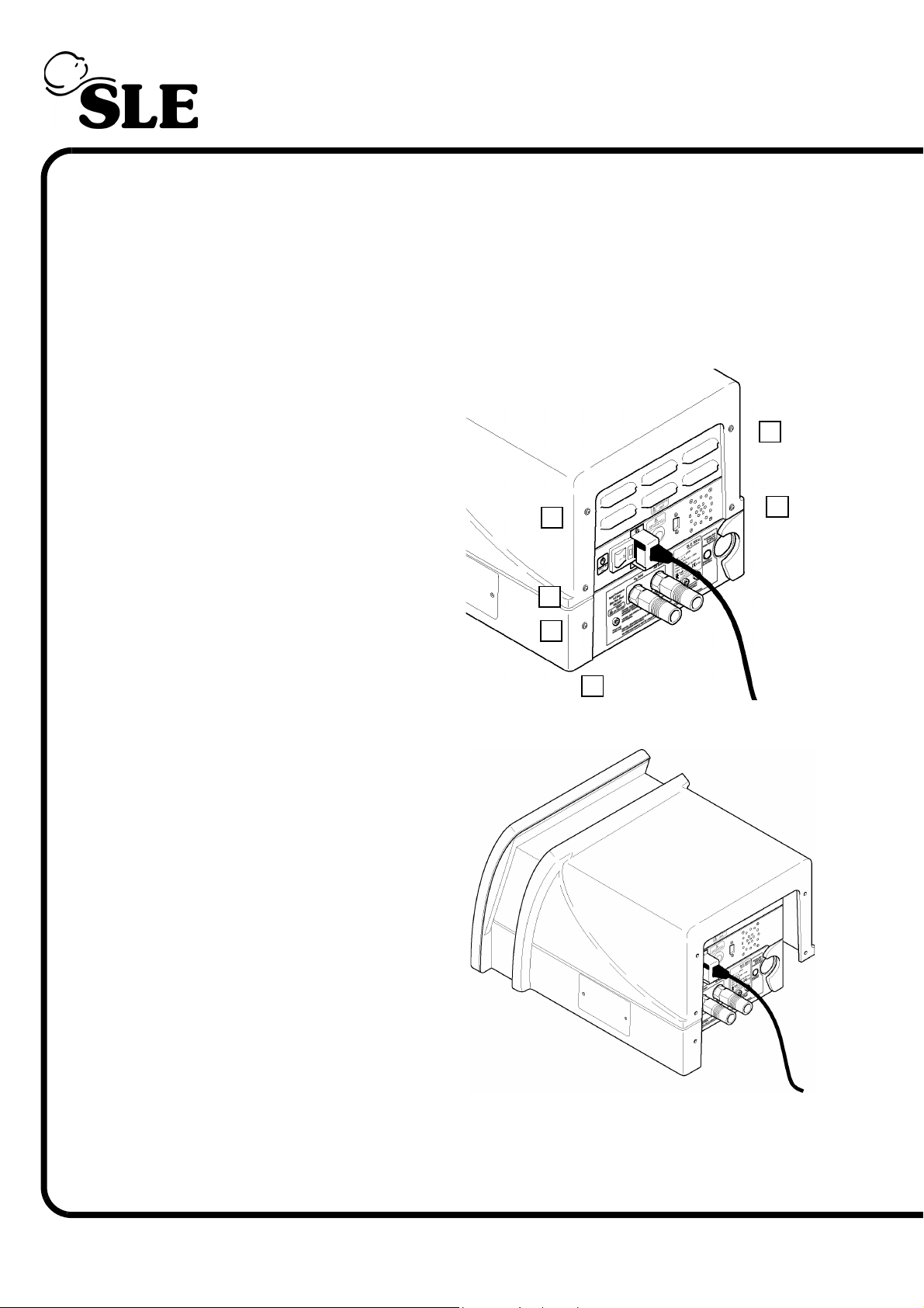
13.2 6, 18, 30 & 42 month preventative maintenance procedure
13.2.1 Ventilator preparation
1. Preventative maintenance should be carried out with the ventilator still attached to the
trolley.
2. Disconnect the air and oxygen supply hoses.
3. Remove the seven fixing screws (A)
indicated from the rear cover.
¦
A
¦
A
A
A
¦
¦
4. Slide the rear cover towards the rear of the
machine. When the lip has been disengaged lift
the cover off.
A
¦
¦
A
¦
Page 88 (Model A)
Page 89
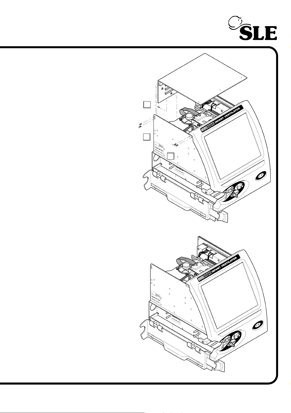
Warning: If the ventilator is under a
warranty agreement removal of the
inner covers may void the agreement. Please refer to the warranty
documentation.
5. Remove the screws (B) to release
the electronic inner cover.
Note: The design of the inner cover
may vary.
The ventilator is now ready for
maintenance.
B
¦
¦
B
¦
B
Note: Keep the ventilator plugged
into the mains supply, but with the
supply turned off. This is to earth
the ventilator and prevent static
build up.
(Model A) Page 89
Page 90
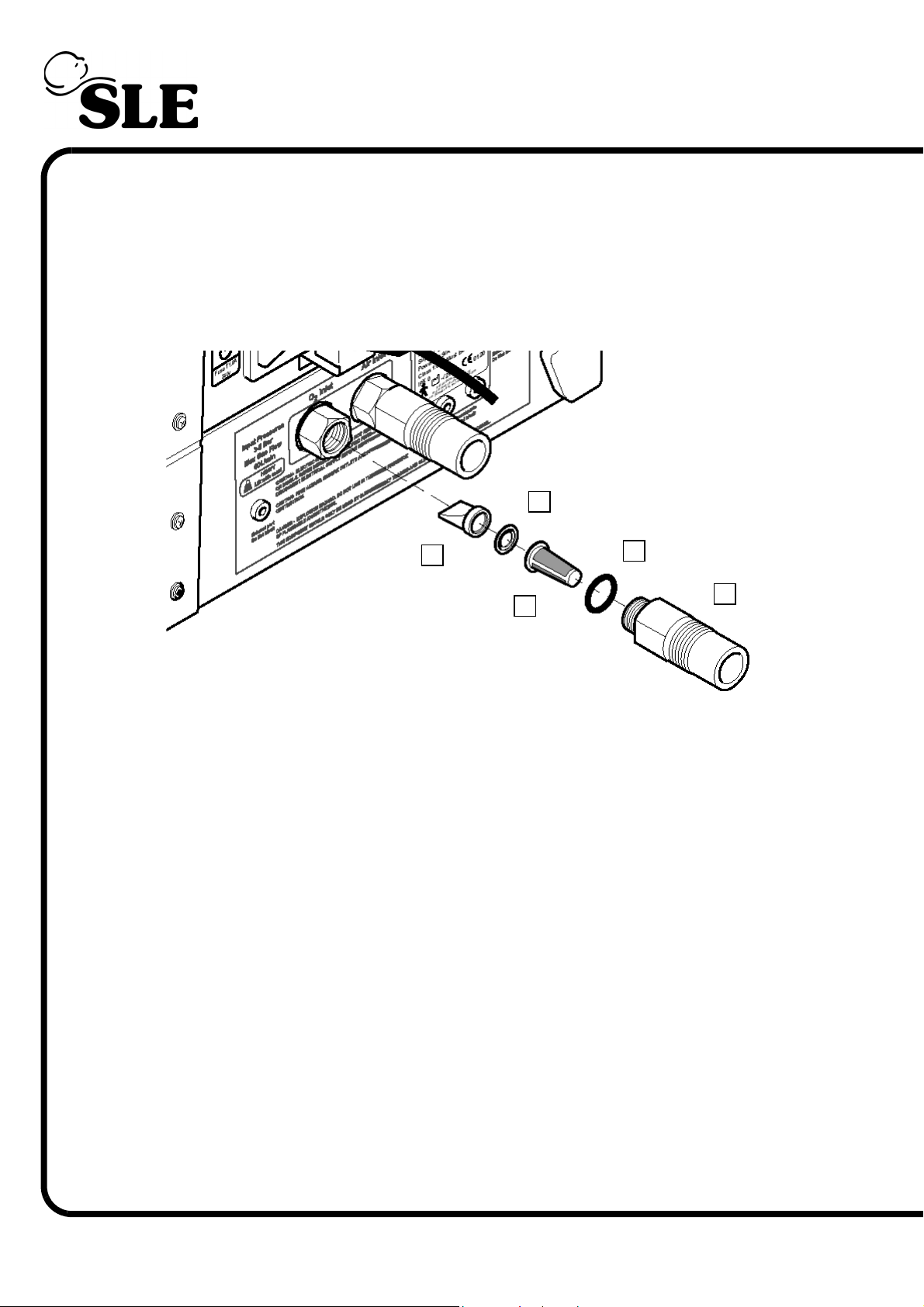
13.2.2 Duckbill and conical filter replacement.
The procedure is the same for both air and oxygen inlets.
1. Using a spanner remove the inlet connector (A).
Note: The O2 connector is a left hand thread and the Air connector is a right hand
thread.
D
¦
¦
E
¦
B
¦
A
C
¦
2. Remove O-ring (N6618) (B),
Nylon filter cone (N2185/06) (C),
Washer (T1170) (D)
Duckbill check valve (N2185/05) (E).
3. Discard the O-ring, Nylon filter cone, washer and Duckbill check valve.
4. Re-assemble with the new components.
Page 90 (Model A)
Page 91
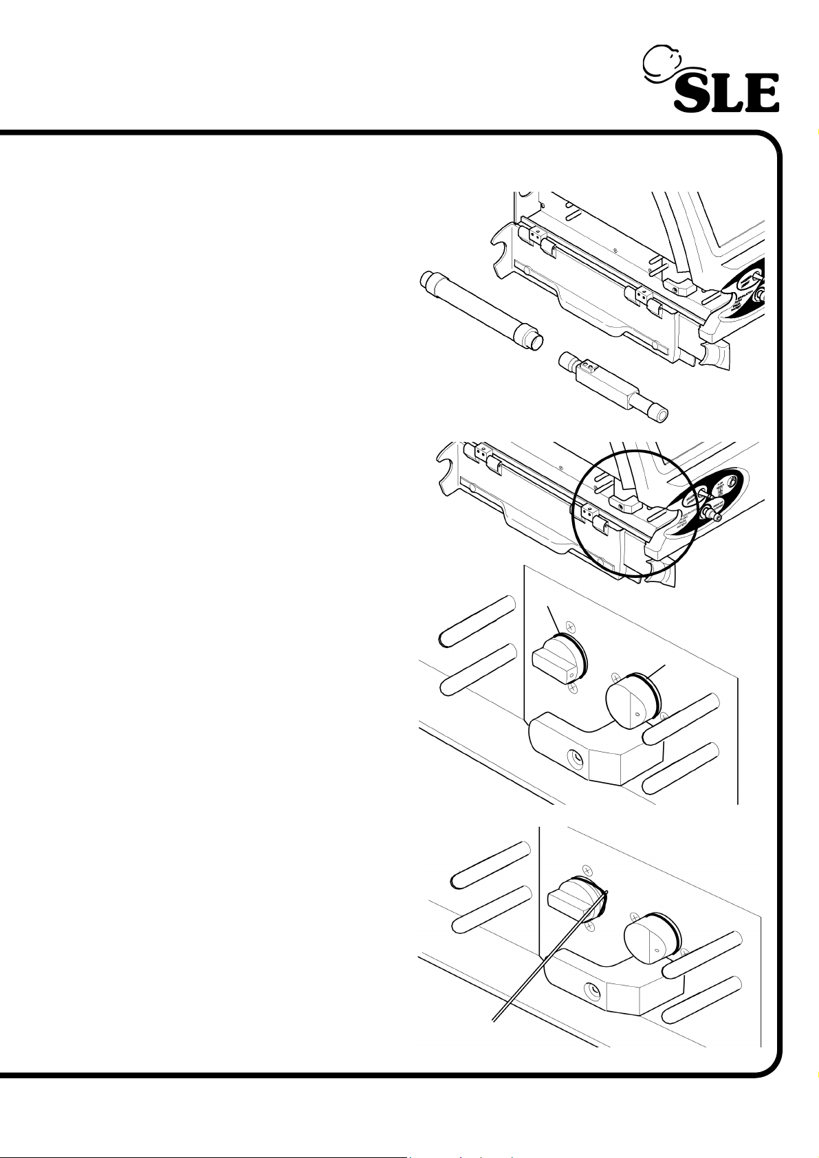
13.2.3 Replacement of N2042 “O” Rings
1. Remove the silencer and exhalation
block from the ventilator.
2. Locate the two ’O’ rings located (A & B)
on gas ports.
3. Using a blunt probe lift out the old ’O’
ring and discard. Repeat the process for
the other ’O’ ring.
4. Wipe the gas ports with an approved
sterilizing solution.
5. Place new ’O’ rings into the grooves.
A
B
(Model A) Page 91
Page 92
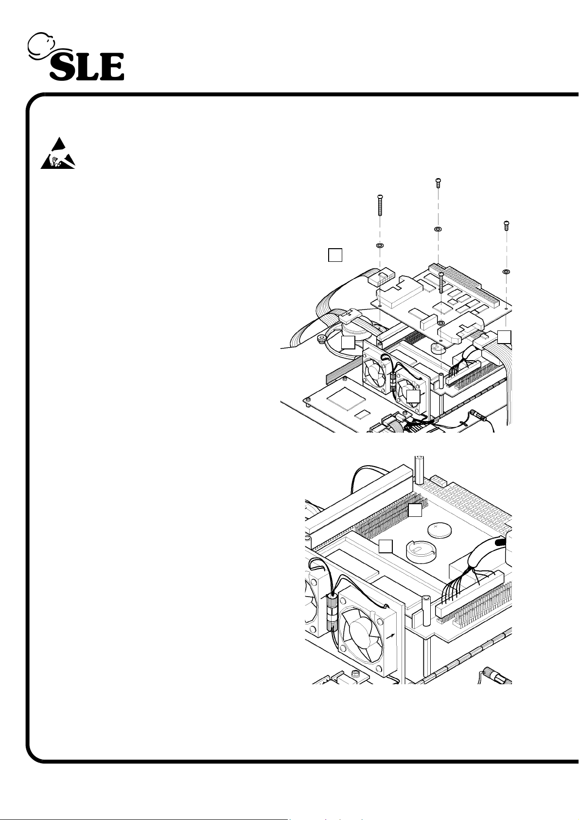
13.2.4 Replacement of the M0909 CPU battery
Replacement of the CPU battery requires the removal of the CAN card.
Warning: the CAN Card and PC board are static sensitive devices.
1. Disconnect the two ribbon cables (A & B)
from the CAN card.
2. Remove the four screws retaining the CAN
card.
3. Gently disconnect the CAN card from the
PC board by lifting the card vertically, until all
the connector pins are disengaged from the
socket.
4. The two nylon spacers (C) are now loose.
Care should be taken to prevent them falling
into the electronic unit.
5. Remove the battery (D) from the battery
housing (E) and discard.
6. Fit the new battery.
7. Re-assemble the CAN card.
8. Re connect the gas hoses to the ventilator.
9. Turn on the ventilator.
A
¦
C
¦
B
¦
¦
C
D
¦
E
¦
10. Re-set the time and date. (Refer to the user
manual)
13. Carry out a full functional test.
Page 92 (Model A)
Page 93

12 & 36 Month Maintenance
(Model A) Page 93
Page 94
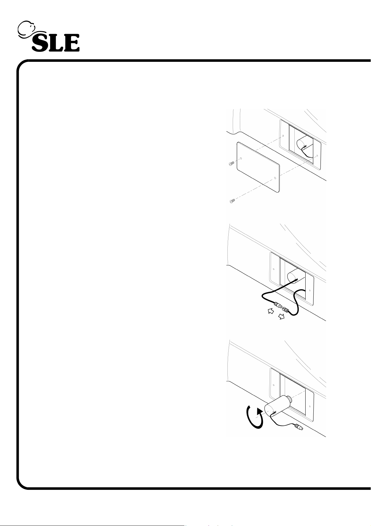
13.3 12 and 36 month preventative maintenance procedure
Carry out a six month preventative maintenance procedure plus the following.
13.3.1 Replacement of N2191/10 O2 Cell
1. Remove the two screws from the cover located on the
right hand side of the ventilator (When viewed from the
front.
2. Pull out the cable until the connector is visible. Gently pull
apart the connector.
3. Unscrew the cell counter clockwise until free and discard.
4. Replacement of the cell is the reversal of removal.
5. In addition to the tests carried out in the previous
preventative maintenace procedure, carry out a 2 point
oxygen calibration routine.
Page 94 (Model A)
Page 95
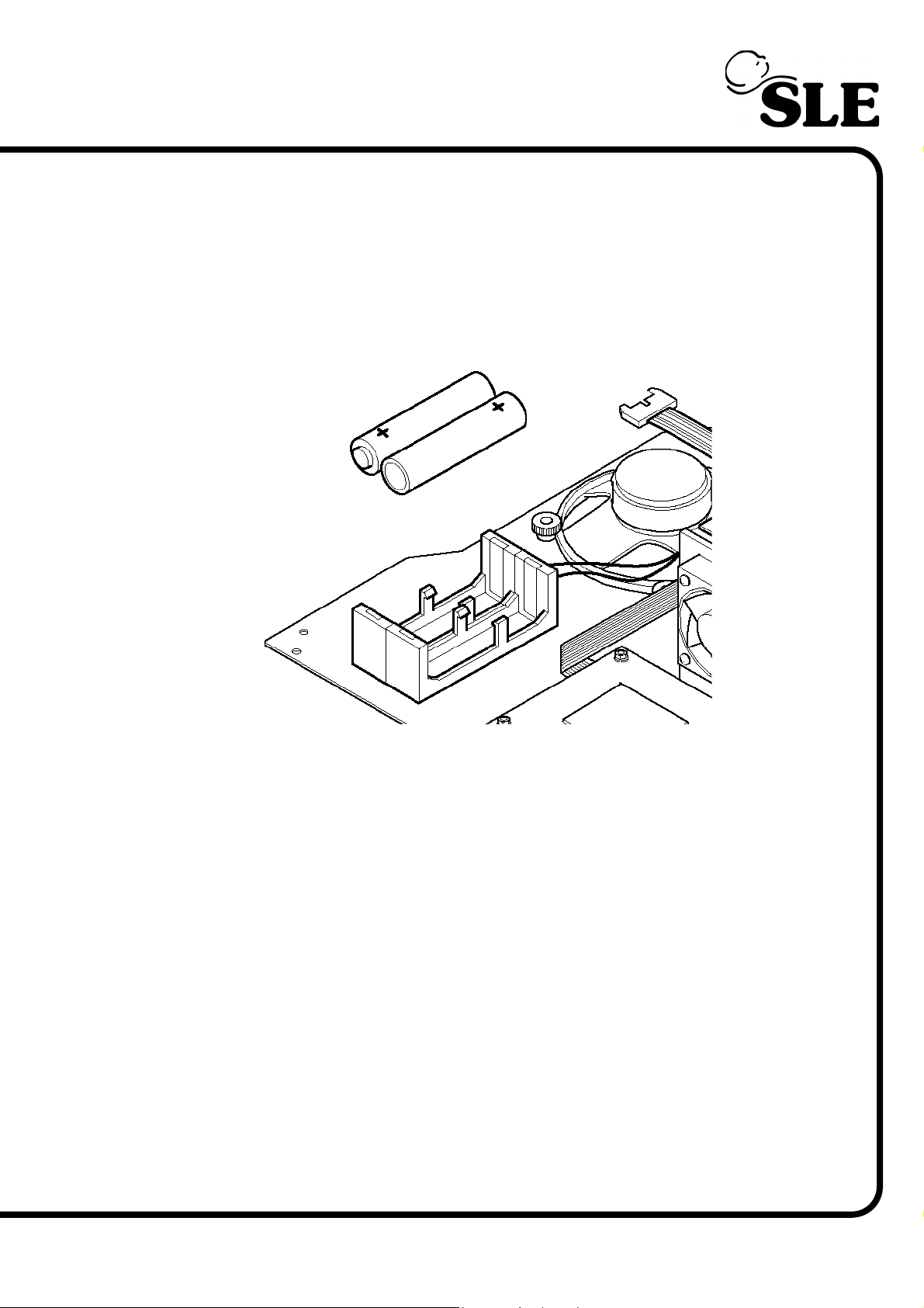
13.3.2 Replacement of CMOS backup batteries
These batteries are fitted to units that have had the CMOS battery backup upgrade.
1. Remove the two AA batteries and discard in accordance with local waste authority
guidlines.
2. Replace the batteries taking care to correctly insert the cells.
(Model A) Page 95
Page 96

This page is intentionally blank.
Page 96 (Model A)
Page 97

24 & 48 Month Hour Overhaul
(Model A) Page 97
Page 98

13.4 24 month and 48 month overhaul procedures
The ventilator has two overhaul points, the first at 24 months or 10,000 hours (whichever is
sooner) and 48 months or 20,000 hours (whichever is sooner).
The 24 month / 10,000 hour overhaul consists of the replacement of the following
components.
These components are supplied in the form of an overhaul kit part Nº: N9010/24
Conical filter Qty 2 Part Nº: N2185/06
Duckbill valve Qty 2 Part Nº: N2185/05
Duckbill washer Qty 2 Part Nº: T1170
“O” rings Qty 2 Part Nº: N6618
CPU battery Qty 1 Part Nº: M0909
Orifice block “O” rings Qty 2 Part Nº: N2042
Oxygen cell Qty 1 Part Nº: N2191/10
Backup battery Qty 3 Part Nº: M0901
AA battery Qty 2 Part Nº: M0484/03
The 48 month / 20,000 hour overhaul consists of the replacement of the following
components.
These components are supplied in the form of an overhaul kit part Nº: N9010/48
Conical filter Qty 2 Part Nº: N2185/06
Duckbill valve Qty 2 Part Nº: N2185/05
Duckbill washer Qty 2 Part Nº: T1170
“O” rings Qty 2 Part Nº: N6618
CPU battery Qty 1 Part Nº: M0909
Orifice block “O” rings Qty 2 Part Nº: N2042
Oxygen cell Qty 1 Part Nº: N2191/10
Pressure regulators (PR3, PR4 & PR6) Qty 3 Part Nº: N6623/S38
Oxygen Blender Assy. Qty 1 Part Nº: L0287
Fresh gas supply solenoid (SV7) Qty 1 Part Nº: N2195/06
Backup battery Qty 3 Part Nº: M0901
AA battery Qty 2 Part Nº: M0484/03
Purge regulator (PR7) Qty 1 Part Nº: N6612
0-30 PSI regulator (PR5) Qty 1 Part Nº: N6613/03
Speed controller (FR1) Qty 1 Part Nº: N6614
Input air pressure regulator (PR1 Qty 1 Part Nº: N6615/01
Input O2 pressure regulator (PR2) Qty 1 Part Nº: N6615/02
High speed jet valves. (SV9,10,11 &12) Qty 4 Part Nº: N6624
O2 calibration solenoid (SV8) Qty 1 Part Nº: N6625/01
Pressure relief valve (PRV1) Qty 1 Part Nº: N2194
Tubing Qty AR Part Nº: N2373
For the 48 month overhaul the user has three options.
Option 1. To carry out a service exchange of the pneumatic unit.
Option 2. To purchase a new pneumatic unit
Option 3. To carry out the overhaul from the N9010/48 kit of parts.
Page 98 (Model A)
Page 99

24 Month / 10,000 Hour Overhaul
(Model A) Page 99
Page 100
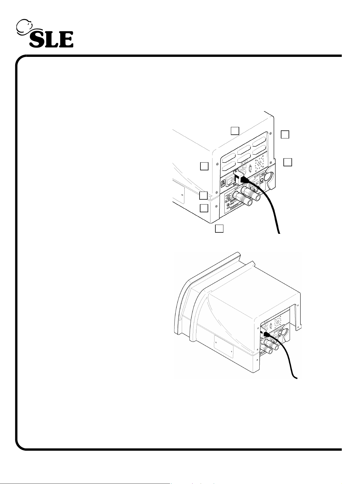
13.5 24 month / 10,000 hour overhaul procedure
The following instructions list the order in which the 24 month overhaul should be carried
out.
1. Remove the seven fixing screws (A)
indicated from the rear cover.
A
¦
A
¦
¦
A
A
A
A
¦
¦
¦
¦
A
2. Slide the rear cover towards the rear of the
machine. When the lip has been disengaged lift
the cover off.
¦
Page 100 (Model A)
 Loading...