

Slant/Fin WH-30, WH-30 D, WH-40, WH-60, WH-80 Installation And Operating Instructions Manual
Page 1
Indirect-Fired Storage Water Heater
Models WH-30 through WH-80
INSTALLATION AND OPERATING INSTRUCTIONS
Contents Page
Ratings and Specifications . . . . . . . . . . . . . . . . . . . . . 2
Installation Requirements . . . . . . . . . . . . . . . . . . . . . . 3
Piping Requirements . . . . . . . . . . . . . . . . . . . . . . . . 3-4
Wiring Requirements . . . . . . . . . . . . . . . . . . . . . . . . 5-6
Operating Procedures . . . . . . . . . . . . . . . . . . . . . . . . . 7
Maintenance Recommendations . . . . . . . . . . . . . . . . . 7
Replacement Parts List . . . . . . . . . . . . . . . . . . . . . . . . 7
Lifetime Limited Warranty . . . . . . . . . . . . . . . . . . . . . . 8
WARNING - HOT WATER CAN SCALD!
Read all of the following important warnings to avoid
the possibility of personal injury, death, or property
damage.
Heater Package includes:
• Fully insulated stainless steel tank with temperature
control well installed.
• Temperature control adjustable from 120°F to 160°F.
• Temperature and pressure relief valve.
• Plumbing hardware for installing T&P valve.
• Keep temperature control on heater at lowest
setting which is satisfactory.
• Always adjust water temperature from taps by starting with a cool mix of water and gradually bring to
warmer temperature.
• Never leave children, elderly or disadvantaged persons unattended where hot w
WARNING TO THE USER:
ater taps are located.
THE INST
O
ARNING
W
eep temperature control on heater at lowest setting
K
•
which is satisf
Installation of a temper
•
of the proper rating for the heater tank size is
required.
Install a tempering device
•
hot water piping which feeds areas where high
temperature water is not demanded.
When ser
•
nections are tight and drain hose is directed away
from all persons or areas where injury or damage can
occur
vicing this installation, mak
.
T
SERVICEPERSONS:
.
y
actor
ature and pressure relief v
ALLER AND
, such as a mixing v
e sure dr
Publication No. WH-40 Rev. B
alv
ain con-
Part No. 66-4001
alv
e, on
e
Page 2

Indirect-Fired Storage Water Heater
Models WH-30 through WH-80
RATINGS & SPECIFICATIONS
Ratings
First Hour Ratings (gph) Heat Exchanger Coil
Storage Heating
Model Capacity at 140° F at 115° F Surface Recommended Pressure
No. (gal) (90°F
∆∆
T) (65°F
∆∆
T) (Sq.Ft) Flow Rate Drop
WH-30 30 156 215 15 6 gpm 4.6 ft
WH-40 40 195 288 15 6 gpm 4.6 ft
WH-60 60 254 348 15 7 gpm 6.8 ft
WH-80 80 300 400 34 10 gpm 12.0 ft
Double wall coil models
WH-40 D
40 110 152 20 6 gpm 8.0 ft
WH-60 D 60 126 174 20 6 gpm 8.0 ft
WH-80 D 80 160 221 20 6 gpm 8.0 ft
Dimensions
Floor to
Boiler
Domestic
Temp.
Cont. Ship
Connections N.P.T
Model In Out In Out Well Domestic Boiler Weight
No. Height Diameter C B A E D In/Out In/Out (lb.)
WH-30 39
WH-40 52
WH-60 52
1
/2"19
1
" 19
/2
1
/2" 231/4"9"4
WH-80 72" 24" 29" 6" 6" 66" 33" 1
1
/4"9"4
1
"9"4
/4
1
/2" 3" 34" 171/2"
1
/2
1
/2" 3" 46" 233/4" 1" 1" 98
" 3" 46" 23
3
3
"
/4
/4" 1" 67
3
" 1" 78
/4
1
/2" 1" 139
Double wall coil models
WH-40 D 52
WH-60 D 52
1
/2" 191/4"9"4
1
"
/2
23
1
/4
9" 4
"
WH-80 D 72" 24" 29" 6" 6" 66" 33" 1
1
/2" 3" 46" 233/4"
1
3" 46" 23
"
/2
3
3
"
/4
/4" 1" male 88
1" 1" male 108
1
/2" 1" male 149
Tank working pressure: 150 psi
.
2
Page 3
INSTALLATION REQUIREMENTS
The installation of this indirect-fired storage water heater must
conform to the following:
. Local, state, provincial, and national codes, laws, regulations
1
nd ordinances.
a
. National Electrical Code (NEC).
2
3. National Plumbing Code (NPC).
4. Building Officials and Code Administrators International
(BOCA).
In any case where instructions in this manual conflict with the
above, let those codes take precedence.
he location of this indirect-fired storage water heater should be
T
ade in consideration of the following:
m
. Install indoors where not subjected to freezing temperatures or
1
physical damage.
2. Install as close to boiler as practical, to minimize piping connections pressure drop and heat loss.
3. For system service convenience, do not install too close to the
boiler or other objects.
4. Install near a floor drain if possible, to prevent possible property damage due to relief valve discharge or equipment leakage.
A drain pan is most suitable for protecting the surrounding
area.
The boiler used to supply hot water to the heater must meet these
requirements:
1. In some jurisdictions the boiler’s operating pressure must be
limited to 30 psig by a safety relief valve.
2. The boiler’s input rating must be within the heater’s recommended sizing guide specifications. Too low an input rating
may cause excessive condensation in the boiler. Too high an
input rating may cause a boiler short cycling condition. Either
of these conditions could be detrimental to the life and performance of the system.
BOILER PIPING CONNECTIONS
. General piping recommendations (See Fig. 4)
1
) Install unions and shutoff valves for servicing conve-
a
ience.
n
b) Use 1” nominal minimum piping size and keep number
of elbows and overall piping length to a minimum to
insure the proper water flow rate to the heater coil.
c) Pipe the supply from the boiler into the coil inlet con-
nection, located at the top of the coil.
d) Pipe the return to the boiler from the coil outlet con-
ection, located at the bottom of the coil. Install a tee
n
ith a drain at the coil connection, with a shutoff valve,
w
o aid in manual air purging.
t
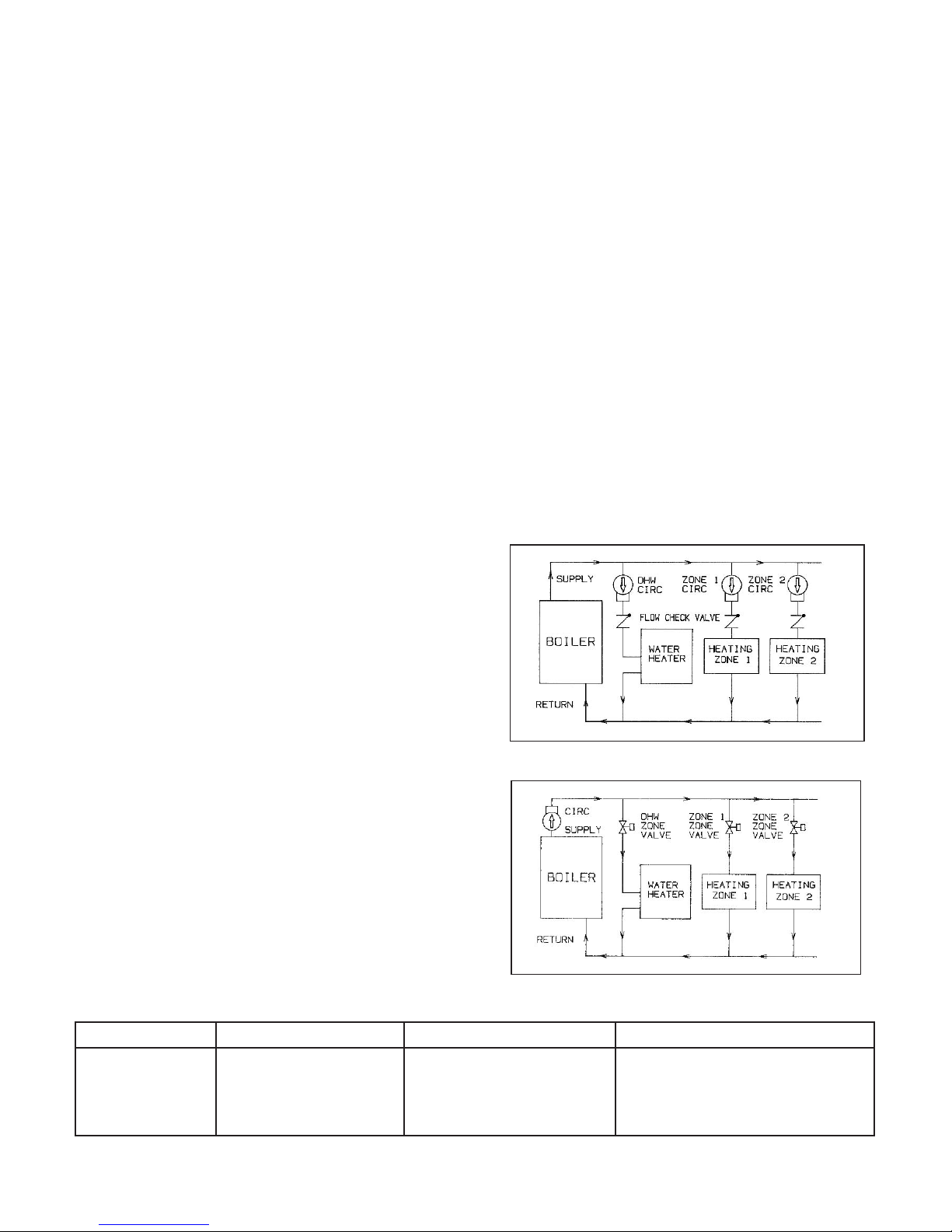
2. Circulator zoning recommendations (See Fig. 2)
a) The preferred location of the circulator pumps for each
zone is on the boiler supply, with the expansion tank
between the boiler and the circulators.
b) A flow check valve must be installed on each zone,
preferably at the outlet side of each circulator pump, to
prevent water flow to other zones when they are not
demanding flow.
3. Zone valve zoning recommendations (See Fig. 3)
a) The preferred location of the circulator pump is on the
boiler supply, with the expansion tank between the
boiler and the circulator.
b) Use zone valves with low pressure drop specifications,
particularly on the water heater zone. A 1” zone valve
is recommended.
Figure 2. Typical piping for circulator zoning
PIPING REQUIREMENTS
TEMPERATURE AND PRESSURE RELIEF VALVE
1. Use only the Watts model or equivalent specified in the chart
below. The rating of each valve meets the absorption capacity of only the model of heater for which it is specified.
2. Must be installed in the run of a tee located in domestic hot
water outlet in heater, unless a dedicated installation port is
provided. No shutoff valves are permitted to be piped between
the relief valve and the heater tank, nor on the T & P discharge
line. (See Fig. 4)
3. Must be positioned to discharge downward, with the dis-
Figure 3.
ypical piping for zone valve zoning
T
charge line within 6” of the floor line and directed towards a
drain or drain pan, if possible. The discharge line must not be
excessively long or reduced in size, be subject to freezing, or
be directly connected to a drain.
Temperature and pressure relief valve specifications
Heater Model T & P valve location T & P valve installs into: Watts Model or Equivalent*
ater outlet
WH-30
WH-40
WH-60
WH-80
*
T & P valve must have 8” long temperature probe.
†
Also applies to double wall coil models WH-40 D, WH-60 D and WH-80 D.
†
†
†
hot w
ater outlet
hot w
hot water outlet 1” NPT Tee with bushing 100 XL-8
dedicated por
t
3
/4”
3
NPT
”
/4
3
NPT
”
/4
Male x F
ee
T
ee 100 XL-8
T
emale nipple
100 XL-8
40 XL-8
3
Male inlet
”
/4
3
Male inlet
”
/4
3
/4” Male inlet
3
Male inlet
/4”
3
Page 4

IPING REQUIREMENTS FOR
P
OMESTIC WATER CONNECTIONS
D
See Fig. 4)
(
1. General piping recommendations
a) Install unions and shutoff valves for servicing
convenience.
b) If the heater is replacing a tankless coil in the
oiler, do not plug tube outlets in the tankless coil
b
after disconnecting from plumbing.
2. Domestic cold water inlet
a) Install a tee with a drain on the tank cold water
inlet nipple.
b) Install the cold water supply piping into the tee on
the tank cold water inlet.
c) If a back flow preventer or check valve is used on
the cold water supply, then a thermal expansion
tank must be installed between the tank and this
device.
d) If excessive water supply pressure is evident, a
pressure reducing v
be necessar
y to prevent relief valve discharge.
alve on the supply line may
Check local codes.
3. Domestic hot water outlet
a) On heater sizes which do not have a dedicated
port for the T & P valve, a tee must be installed
onto the tank hot water outlet nipple for the installation of the T & P valve. See T & P valve installation requirements on page 3.
) Install the hot water supply piping into the branch
b
of the tee (if used) on the tank hot water outlet.
c) A thermal loop can be arranged on this piping to
prevent thermal siphon action of the hot water
when not in use.
d) A mixing valve can be installed on hot water pip-
ing which feeds areas where high temperature
water is not desired. This will allow for higher
temperature water to be delivered to areas where
it is demanded without endangering the user at
the lower temperature fixtures.
Figure 4. Indirect-fired storage water heater piping
4
Page 5

IRING REQUIREMENTS
W
1. General wiring requirements
a) Wiring must conform to National Electrical Code
in U.S.A., C.S.A. C22.1 Canadian Electrical Code
Part 1 in Canada, and any other national, provin-
ial, state, or local code requirements having
c
urisdiction.
j
b) All line voltage wiring must be a minimum 18
gage.
c) A separate service switch for the water heater
electrical circuit is recommended. This switch
Figure 5. Wiring to a gas boiler with circulator zoning
ust not turn off the boiler or other components in
m
the heating system.
d)
IMPORTANT NOTE:
All wire connections to “T-T” or “A-A” terminals on boiler control must be from an isolated circuit which does not carry voltage from
an external source. Any component which
oes not have isolated end switches must not
d
e used unless a relay is added with the dry
b
contacts wired to these terminals.
Figure 6. Wiring to an oil boiler with circulator zoning
5
Page 6

. Circulator zoning wiring (See Fig. 5, 6)
2
a) Components must be wired to ensure that only the
circulator for each zone is powered on a demand
for supply water from that zone.
b) Multi-zone switching relays are available as an
alternative to individual zone relays to simplify the
wiring and provide priority on domestic hot water
demand.
Figure 7. Wiring to a gas boiler with zone valves.
. Zone valve zoning wiring (See Fig. 7, 8)
3
a) Components must be wired to ensure that only the
zone valve for each zone is powered on a demand
for supply water from zone, and that the circulator
is powered on a demand from any zone.
b) The transformer used to power the zone valves
must be sized for the load of all the zone valves in
system.
Figure 8. Wiring to an oil boiler with zone valves.
6
Page 7

PERATING PROCEDURES
O
1. Filling the heater tank
a) Make sure all drain valves on the cold or hot water supply
piping are closed.
b) Open the nearest hot water faucet and any shutoff valves
n the domestic hot water supply piping from the tank out-
o
et.
l
) Open the shutoff valve on the cold water supply piping to
c
the tank inlet.
d) Allow the cold water supply to fill the tank by leaving the hot
water faucet open until all air is purged from the tank and
piping, and a steady flow of water is observed from the
faucet.
e) Close the hot water faucet, but leave all piping shutoff
alves open.
v
) Any other hot water faucets fed by this heater may be
f
pened to purge air from their supply piping, and then shut
o
off after a steady flow of water is observed from the faucet.
2. Filling the heater coil
a) Attach a hose to the drain valve on the coil outlet (return to
boiler). Place the end of the hose into a drain or bucket in a
manner that will prevent potentially hot water from spraying
on any persons in the area.
b) If a shutoff valve has been installed between the drain valve
and the boiler return, keep this valve shut at this time.
c) Open the shutoff valve (and on a zone valve system, man-
ually open zone valve) on the supply piping from the boiler.
d) Open the drain valve on the coil outlet to purge the air from
the coil. When a steady flow of water is observed from the
drain, then open the shutoff valve on the return piping to the
boiler. Additional air from the return piping should purge
itself at this time. Close the drain valve when the steady flow
of water is again observed.
e) Remove the hose from the drain valve. Leave the drain
valve closed. Leave all shutoff valves open. Return zone
valve to automatic operation.
f) Purge air from remaining zones, if necessary. Check boiler
gauge pressure reading afterward to be appropriate. 15 psi
is normal for most installations.
3. Operating the heater
a) After the system has been manually purged of its air, and
all components (valves, vents, controllers) have been set
properly, the boiler can be started. NEVER operate this
heater until this has been done.
b) The maximum setting for the boiler water supply to the
heater coil is 220° F.
c) The maximum setting for the heater tank temperature con-
trol is 160° F. Unless there is specific demand for very high
ature domestic hot water
temper
be set at the lo
wer end of the temperature range of adjust-
, the control setting should
ment to reduce the risk of scalding injury. Some areas
.
require that the tank control setting be below 130
°
d) When the temperature of the water in the heater tank is
below the setting on the tank control, the boiler and circulator should start. If a zone valve is used for this zone, it
hould open at this time. When the temperature of the
s
ater in the heater tank reaches the temperature setting on
w
he tank control, the boiler and circulator should turn off
t
(and zone valve, if used, should close). If other zones for
heating are in demand, this would also run boiler and circulator(s). Cycling of the boiler on high limit is not abnormal, particularly if only one zone is in demand. On initial
startup with a cold tank, a considerable amount of time may
be required for the tank to reach desired temperature.
aintenance recommendations:
M
. Temperature and pressure relief valve operation check
1
a) Once a year, the T & P valve must be manually operated to
ensure safe and proper operation.
b) Make sure that the discharge line from the T & P valve is
directed towards a drain or some collection method, and
will not spray onto any person.
c) Use lever on T & P valve to open. A steady discharge of hot
water should be noticed. After releasing this lever, the
T & P valve should close and fully shut off this flow.
d) If the T & P valve does not function properly, it must be
replaced with the same model or its equivalent. DO NOT
plug the outlet of this valve if a dripping condition occurs.
2. Flushing the heater tank
a) Once a year, or if a persistent discolored water condition
exists, the heater tank should be manually flushed to
remove possible sediment accumulation.
b) Turn off the boiler before draining the heater tank.
c) Attach a hose to the drain valve on the cold water supply to
the tank. Place the end of the hose into a drain or bucket in
a manner that will prevent potentially hot water from spray-
ing on any persons in the area.
d) Close the shutoff valve on the cold water supply to the tank.
e) Open the drain valve on the cold water supply and drain
down tank completely. Open the T & P valve or a nearby
faucet to break vacuum on drain.
f) After the heater tank is drained, close the drain valve and
reopen the cold water supply valve to refill the tank. The
introduction of water into the tank should act to stir up sed-
iment accumulations which can then be drained through
the drain valve. Go back through the draining and filling
process until clean water is observed passing out the drain.
g) Once clear water conditions are accomplished, make sure
the heater tank and all domestic hot w
purged of air and discolored w
ater. Leave the drain closed,
ater supply piping is
check for the T & P valve to be properly seated, and make
sure all shutoff valves for the hot and cold water supply are
left open. The boiler can then be returned to operation.
TS LIST
FPT x 2
AR
1
/2
”
long -br
REPLA
*
CEMENT P
Description Part Number WH-30 WH-40* WH-60* WH-80*
Temperature control -Honeywell 4080B-1295 664131000 X X X X
Temperature and pressure relief
valve - Watts 100 XL-8 664121000 X X X
Temperature and pressure relief
valve - Watts 40 XL-8 664122000 X
Trenton inverted nipple
3
”
/4
3
” NPT brass tee 664126000 X X
/4
1” NPT brass tee 664127000 X
3
” NPT x 1” NPT reducer bushing - brass 664128000 X
/4
Also applies to double wall coil models WH-40 D, WH-60 D and WH-80 D.
MPT x
3
”
/4
ass
664129000
Used on heater model
X
7
Page 8

Limited Warranties for Model WH Indirect-fired Water Heaters
LIFETIME LIMITED WARRANTY FOR HEATERS IN
RESIDENTIAL USE
First year warranty includes
Repair or replacement for a period of one year after original
installation of all parts of any Slant/Fin Model WH indirect-fired
water heater found to be defectively manufactured.
Lifetime limited warranty of water heater
Warranty is effective for as long as the heater is owned by the
original purchaser. It applies only if the heater is installed in a
single family dwelling and only if it has remained at all times in
the location at which it was originally installed. “Single family
dwelling” shall also mean usage in a multiple family dwelling
providing that the Slant/Fin indirect-fired water heater services
only one family unit in a multiple family dwelling.The warranty
includes repair or replacement of any Slant/Fin Model WH indirect-fired water heater stainless steel tank or heat exchanger coil
having a defect or malfunction that results in a water leak from
the outside jacket, inner tank, or heat exchanger coil as a result
of normal use and service, at a cost to consumer equal to the
percentage indicated below of the
manufacturer's then list price for the
replacement parts or nearest
comparable model replacement
heater: This warranty extends only
to heaters in household use and
excludes heaters which are at any
time operated at a temperature
above 150°F.
Year consumer
2 thru 15 0%
16 thru 20 50%
21 & after 75%
Percentage
paid by
(of list price at
time of claim)
5-YEAR LIMITED WARRANTY FOR HEATERS IN
COMMERCIAL USE
This commercial use warranty applies to all heaters not falling in
the above definition of a residential setting. A Slant/Fin indirectfired water heater shall be deemed to be used in a commercial
setting if at any time it is operated at a temperature above 150°F.
First year warranty includes
Repair or replacement for a per
installation of all parts of any Slant/Fin Model WH indirect-fired
w
ater heater f
ound to be defectively manufactured.
iod of one y
ear after original
ADDITIONAL INFORMATION - RESIDENTIAL AND
COMMERCIAL WARRANTIES
arranties extend only to heaters which have been properly
W
installed, operated and maintained in accordance with Slant/Fin
installation instructions and all applicable codes. Slant/Fin makes
no express warranties other than the warranties contained herein.
First-year warranty excludes
All labor charges incurred by any person in connection with the
examination, removal, and repair of parts claimed to be defective
and the installation of replacement parts. Slant/Fin may determine it to be necessary that a part claimed to be defective be
returned to Slant/Fin. In this case, the cost of shipment to
Slant/Fin is borne by the consumer.
Procedure for warranty service
For warranty service, provide the person who installed your
Slant/Fin heater with the following information: heater model number and serial number (from the heater rating plate) and the date
of installation. That person will notify the Slant/Fin wholesaler
from whom the heater was purchased. Alleged defective part(s)
must be returned through trade channels and replacement part(s)
or replacement heater will, if warranty conditions are met, be provided by Slant/Fin through the wholesaler. If there are any questions about the coverage of this warranty, please contact Slant/Fin
at the address shown below.
Limitations on implied warranties and damages
Slant/Fin's sole obligation in the event of a breach of any implied
warranty (including, but not limited to, implied warranties of merchantability and fitness for a particular purpose) is limited to
repair or replacement, and all such warranties are limited in duration to the period of time after the date of original installation as
stated above. This warranty does not cover claims for incidental
or consequential damages resulting from a breach of any express
or implied w
Some states do not allow limitations on how long an implied warranty lasts or the exclusion or limitation of incidental or consequential damages, so the above limitation or exclusion may not
apply to you. This warranty gives you specific legal rights, and
you may also have other rights which vary from state to state.
arranty or any other reason.
Second through fifth years of limited
commercial use warranty
During the second through fifth years, the warranty includes
repair or replacement of any Slant/Fin Model WH indirect-fired
ater heater stainless steel tank or heat e
w
ect or malfunction that results in a w
def
jacket, inner tank, or heat exchanger coil as a result of normal
use and ser
©Slant/Fin Corp. 2000. Printed in the U.S.A. 905. Publication No. WH-40.
vice
.
xchanger coil having a
ater leak from the outside
SLANT/FIN CORPORATION, Greenvale, N.Y. 11548 • Phone: (516) 484-2600
(516) 484-5921
AX:
F
• Canada:
Slant/Fin
TD/L
L
TEE
, Mississauga, Ontar
www.slantfin.com
io
 Loading...