

Page 1
Printed in U.S.A. 1114 Publication No. VSPH-UIM
Part No. 455036 Rev. A
Residential • Gas fired • Hot Water Boilers
User’s Information Manual
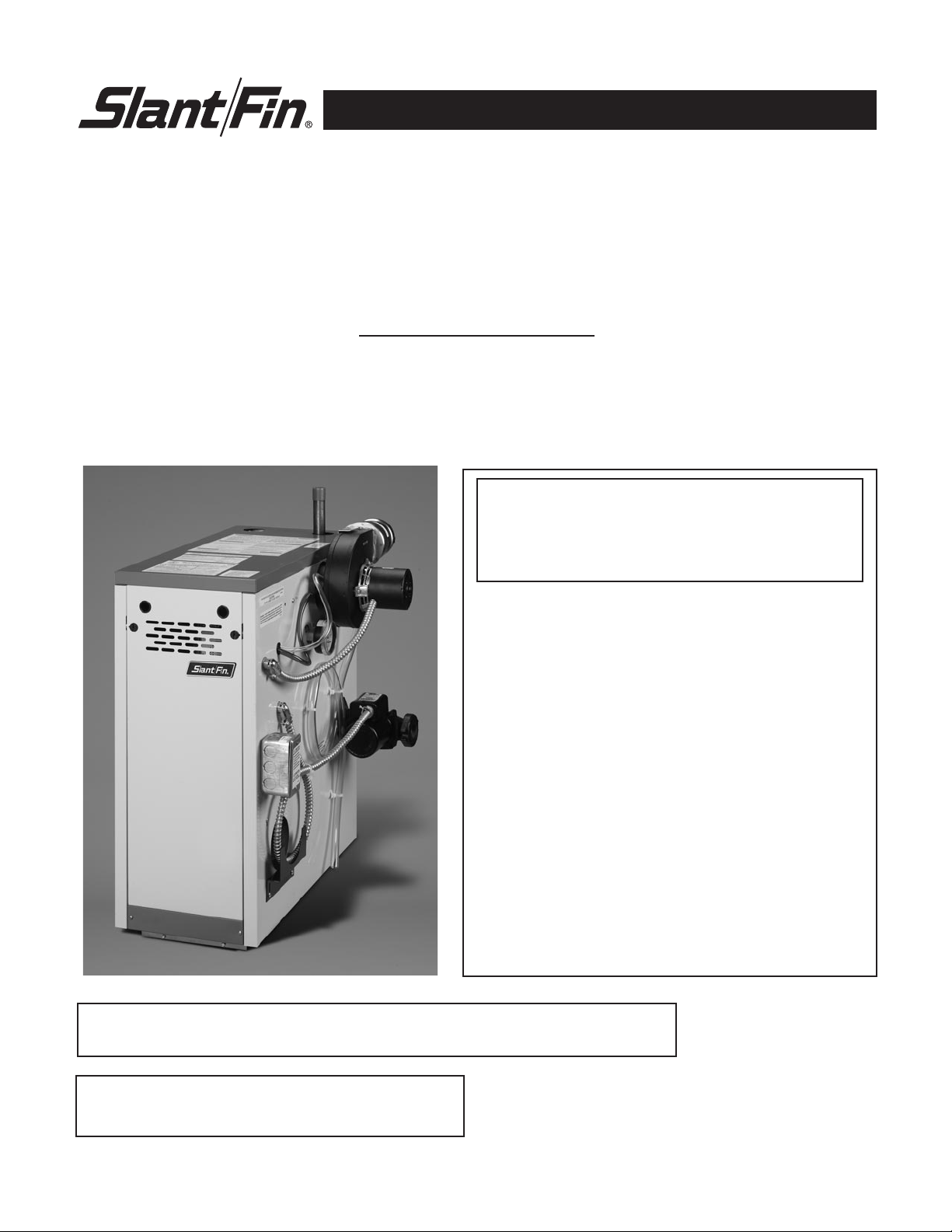
VICTORY VSPH SERIES GAS BOILERS
Sealed Combustion - Direct Vent Models
FOR YOUR SAFETY:
• Before operating this boiler, READ this manual.
• DO NOT attempt to install, service or repair this boiler yourself. There are no user serviceable
parts. Contact a qualified service agency if your boiler needs repair or maintenance. Ask your gas supplier for a
list of qualified service agencies.
• A qualified service agency should inspect the venting system of this boiler on an annual basis.
__ DO NOT store or use gasoline or other
flammable vapors and liquids in the
vicinity of this or any other appliance.
__ WHAT TO DO IF YOU SMELL GAS
• DO NOT try to light any appliance.
• DO NOT touch any electrical switch
• DO NOT use any phone in your
building.
• Immediately call your gas supplier
from a neighbor’s phone. Follow the
gas supplier’s instructions.
• If you cannot reach your gas supplier,
call the fire department.
__ Installation and service must be performed by
a qualified installer, service agency or the gas
supplier.
WARNING: If the information in this manual is not
followed exactly, a fire or explosion may result
causing property damage, personal injury or loss
of life.
Your gas boiler must be installed and serviced by a qualified service agency or gas
supplier. The lack of proper service can result in a dangerous condition.
This manual must be left with owner, hung on or
adjacent to the boiler. Owner should retain manual
for future reference.
Page 2
VICTORY VSPH Models
2
WELCOME TO OUR VALUED CUSTOMER
You are now the owner of a Slant/Fin Victory VSPH gas-fired
boiler, another quality heating product designed and manufactured by an industry leader, to provide your family with
many years of reliable comfort and trouble-free performance.
The care and maintenance of your new boiler is important to
prevent a hazardous condition which might result form lack
of proper servicing. Therefore, you should perform regular
“owner” inspections as described in this manual (and report
any concerns to a qualified service technician) as well as
have your boiler serviced by a qualified service technician at
least once a year, preferably before the beginning of each
heating season.
LIGHTING INSTRUCTIONS
Locate, read and then follow the procedures on the lighting
instructions label attached to the boiler. For reference, we
have reproduced those instructions in this manual.
DO NOT use this boiler if any part has been
underwater. Immediately call a qualified service
technician to inspect the boiler and to replace
any part of the control system and any gas
control which has been underwater.
WARNING
Should overheating occur or the gas supply
fail to shut off, DO NOT turn off or disconnect
the electric supply to the circulator pump.
Instead, shut off the gas supply at a location
EXTERNAL to the appliance.
WARNING
SLANT/FIN DOES NOT PERMIT THE USE OF
VENT DAMPERS ON VICTORY SERIES
BOILERS. OTHER DAMPERS OR DEVICES
WITH SIMILAR PURPOSE ARE NOT
PERMITTED.
Keep the boiler area clean and free of all materials that can burn.
NEVER close or reduce openings that supply air for the boiler fire and for ventilation.
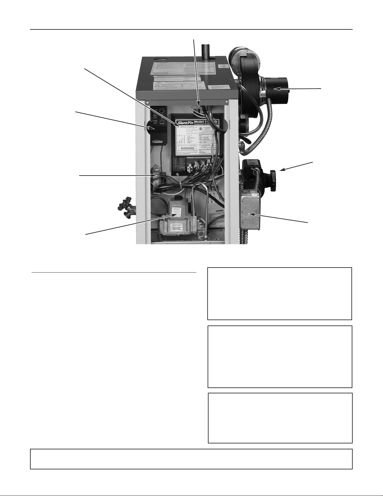
Figure 1. Location and Identification of parts.
Air flow proving switch
Blower assembly
Circulator
Gas valve
120/24V transformer
Water
Temperature
Control
Integrated boiler control
Junction Box
Page 3
VICTORY VSPH Models
3
INSPECTION
Your boiler and heating system will last an indefinitely
long time at full efficiency, if it is inspected regularly
and is kept in good repair and adjustment. You, the
user, should make regular inspections, and report any
problems to your service agency. At regular intervals,
you should have that agency inspect the system,
clean the boiler and make repair adjustments as necessary. what you and the service agency should do is
listed below. Contact your gas supplier for a list of
qualified service and repair agencies.
USER INSPECTION
The user should make the following inspections at
least once each month during the heating season
and once just before cold weather starts.
VSPH boilers maybe installed and vented either
as direct-vent boiler, which all air for combustion is
obtained directly from outside through the air intake
piping or as non-direct-vent boiler, which all air for
combustion is taken from inside the boiler room.
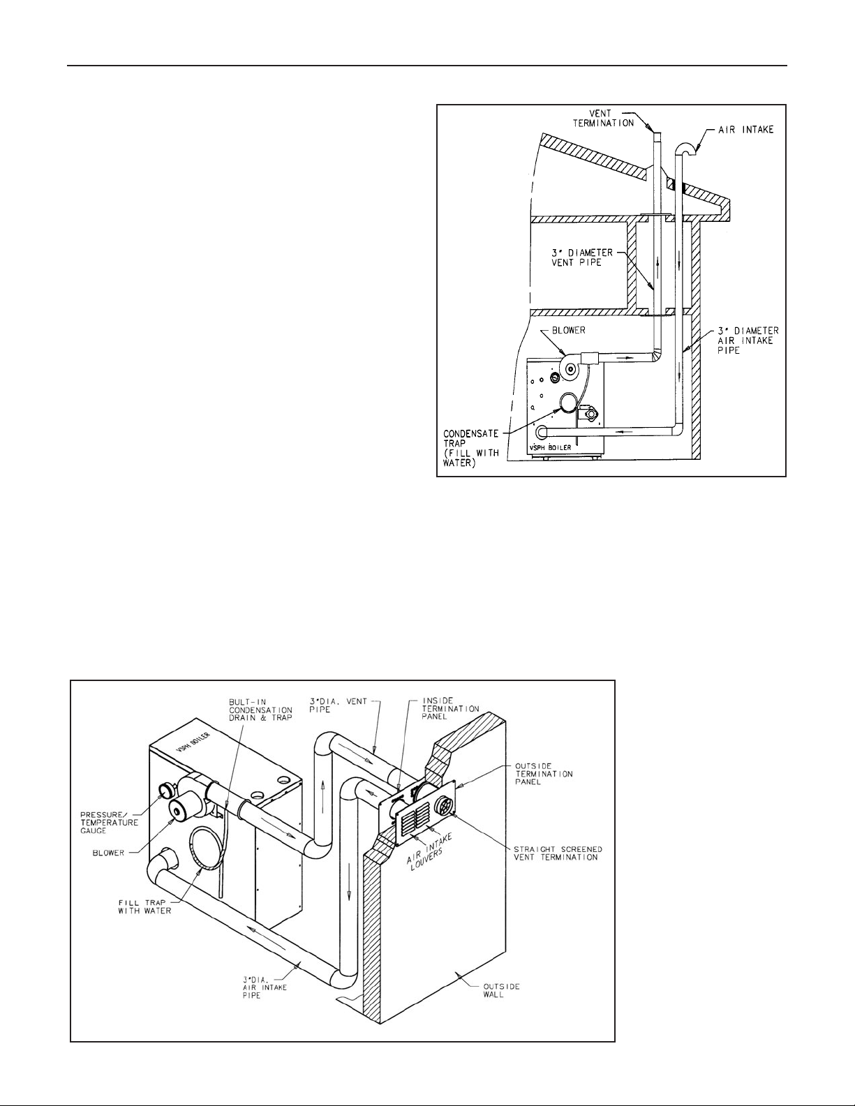
Typical direct-vent installations are shown on FIgures
2 and 3. Non-direct-vent installation is shown on Figures 4, 5 and 6.
1. VENTING AND AIR INTAKE SYSTEM REGULAR
INSPECTION
Inspect the system regularly for condensation, corrosion
and/or physical damage. A qualified professional should
service the boiler annually and include such an inspection at that time. The homeowner should look over the
system monthly for damage, water stains, any signs of
rust, other corrosions or separation of the vent and air
intake piping (if direct-vent).
Figure 2.
Figure 3.
Should an inspection turn up signs of condensation, corrosion or damage, the boiler should be shut down immediately and the condition should be corrected by a qualified
professional.
If the boiler is vented horizontally through the wall, the outside termination, louvers and screen should be checked
for any debris blocking the opening and cleaned as
required.
Page 4

VICTORY VSPH Models
4
Figure 4.
Figure 5.
Page 5

VICTORY VSPH Models
5
Figure 6.
2. CONDENSATION DRAIN
All Victory VSPH boilers are equipped with a built-in
condensation drain and trap. The trap loop must be filled
with water. DO NOT operate the boiler without filling the
trap with water to prevent flue gas discharge into space.
Periodic inspection should be made of this assembly for
deterioration of the tubing and to insure that the trap is
not plugged. If it is plugged or appears to have excessive sediment in it, it should be removed from the drain
assembly, straightened out to clear the obstruction,
reformed, filled with water and reinstalled as before.
3. PIPING INSPECTION
Look at all water piping. There should be no leaks or
signs of leaks at any pipe joints or around the boiler.
4. SYSTEM WATER PRESSURE INSPECTION
The temperature and pressure gauge indicates the
pressure in the boiler at each water temperature. For
most installations, it should indicate about 12 to 15 psi
pressure when temperature is about 70 to 100F and
from 15 psi to 25 psi when temperature is up to 240F.
FOR YOUR SYSTEM, there is one correct pressure for
each temperature. ASK YOUR INSTALLER OR SERVICEPERSON TO EXPLAIN AND SHOW YOU. Learn
what normal pressure to look for. If pressure rises from
normal, the relief valve will open to relieve the pressure.
Call your service organization if pressures are higher or
lower than normal, and if the relief valve spills water.
Repair or adjustment is needed.
5. UNUSUAL NOISE
Stand near the boiler and look and listen. As the burners start and shut off, there should be no unusual noise.
6. BOILER ROOM AIR SUPPLY
Ample boiler room fresh air is required for combustion
(non-direct vent installation) and ventilation (direct-vent
installation).
Check air vents for continuous positive supply of air as
required. Air needs are greatest in cold weather if boiler
installation is non-direct vent method. Air vents must be
open and free of obstruction.
Warning: The flow of combustion and ventilating air to the
boiler should not be obstructed.
Warning: If you find any problem during your inspection, call
for service immediately.
Page 6

VICTORY VSPH Models
6
ANNUAL SERVICE AND GENERAL MAINTENANCE
A trained and qualified service technician should perform inspection and general maintenance listed in
Installation and Operating Instructions (Publication No.
VSPH-40) before each heating season and at regular
intervals.
SAFETY AND OPERATING INSTRUCTIONS
Follow the lighting instructions in this manual. These
instructions are also attached to the boiler.
SAFETY INFORMATION
For Your Safety Read Before Operating
A. This appliance is equipped with an ignition device
which automatically lights the pilot. DO NOT try to light
the pilot by hand.
B. BEFORE OPERATING smell all around the appliance
area for gas. Be sure to smell next to the floor because
some gas is heavier than air and will settle on the floor.
WHAT TO DO IF YOU SMELL GAS:
• DO NOT try to light any appliance.
• DO NOT touch any electric switch: DO NOT use any
phone in your building.
• Immediately call you gas supplier from a neighbor’s
phone. Follow the gas supplier’s instructions.
• If you cannot reach your gas supplier, call the fire
department.
C. Use only your hand to turn the gas control knob. Never
use tools. If the knob will not turn by hand, don’t try to
repair it, call a qualified service technician. Force or
attempted repair may result in a fire or explosion.
D. DO NOT use this appliance if any part has been under
water. Immediately call a qualified service technician to
inspect the appliance and to replace any part of the
control system and any gas control which has been
under water.
OPERATING INSTRUCTIONS
1. STOP! Read the safety information above.
2. Set the thermostat to lowest setting.
3. Turn off all electric power to the appliance.
4. This appliance is equipped with an ignition device
which automatically lights the pilot. DO NOT try to light
the pilot by hand.
5. Remove jacket front panel
6. Turn gas control knob clockwise to “OFF”.
DO NOT force.
7. Wait five (5) minutes (longer for propane) to clear out
any gas, then smell for gas, including near the floor. If
you then smell gas, STOP! Follow “B” in the safety infor
mation above on this page. If you don’t smell gas, go to
next step.
8. Turn as control knob counterclockwise to “ON”.
9. Replace jacket front panel.
10. Turn on all electric power to the appliance.
11. Set thermostat to desired setting.
12. If the appliance will not operate, follow the instructions
“To Turn Off Gas to Appliance” and call your service
technician or gas supplier.
To Turn Off Gas to Appliance
1. Set thermostat to lowest setting.
2. Turn off all electric power to the appliance if service
is to be performed.
3. Remove jacket front panel.
4. Turn gas control knob clockwise till knob
stops, then continue to “OFF”. Do not force.
5. Replace jacket front panel.
Removing Jacket Front Panel
1. Turn black screws
1
⁄4 turn to open position.
2. Remove front panel.
To replace the panel, reverse procedure.
INTEGRATED BOILER CONTROL
The integrated boiler control monitors the status of the
room thermostat, high limit control (Aquastat), pressure
switch (air flow proving switch) and the flame sensor. It
controls the operation of the circulator, inducer motor
(blower), gas valve and spark for pilot ignition. The boiler
control also determines the sequence of operation and
timing for pre and post purge periods, trial for ignition adn
lockout. The control indicator lights (LED’s) provide information of boiler operation when lights are steady on or
diagnostic information when they are flashing in order to
help to determine the cause of boiler failure.
WARNING: If you do not follow these instructions exactly, a
fire or explosion may result causing property damage, personal injury or loss of life.
0FF0FF
ONON
HONEYWELLHONEYWELL
GAS GAS
INLETINLET
GAS CONTROL KNOBGAS CONTROL KNOB
SHOWN IN "OFF"SHOWN IN "OFF"
POSITIONPOSITION
OUTLETOUTLET
Gas Valve VR8204 or VR8304
Figure 7.
Page 7

VICTORY VSPH Models
7
Flame LED (Red)
Pressure Switch LED (Red)
Hi Limit LED (Red)
Thermostat/Circ. LED (Red)
Power LED (Green)
Figure 8.
INTEGRATED BOILER CONTROL
Page 8

VICTORY VSPH Models
8
O = LED off = LED steady on
A. NORMAL OPERATION - STATUS OF INDICATOR LIGHTS (LED’S)
Standby-Boiler waits for call for
heat
Thermostat calls for heat
Circulator on
Boiler water temperature below
high limit setting
Inducer on
Pressure switch contacts closed
30 seconds pre-purge period
Trial for ignition
Gas valve open
Pilot flame and main burners on
Boiler heating period
Thermostat call for heat ends
Circulator off
15 seconds post purge period.
Burners off.
DESCRIPTION OF OPERATION
POWER
LED
TSTAT/CIRC
LED
LIMIT
LED
PRESS
SWITCH
LED
FLAME
LED
O
O
O
O
O
O
O
O
O
O
O
O
B. DIAGNOSTIC FLASH CODES
Flashing LED’s provide diagnostic information
WARNING: Only a trained, experienced service technician should perform troubleshooting. Turn off all electric power to
the boiler before service
POWER LED * 120 V power supply. Polarity is reversed Reverse Hot and NEUTRAL wires in the junction
box.
POWER + TSTAT/CIRC LED’S * 48 VAC on thermostat circuit. Check and correct the thermostat or zone valves
wirings.
POWER + PRES SWITCH LED’S * Pressure switch contacts are closed prior to Check air pressure switch.
energizing the blower motor or does not close Check hose connections to pressure switch.
within 5 minutes of the blower being turned on. Check for obstruction/restriction in venting, air
intake piping and termination.
POWER + FLAME LED’S * Flame sensed without call for heat. Remove air box front panel.
Turn off power for at least 45 seconds.
Check if pilot flame exists during pre-purge
period (first 30 seconds). If pilot flame exists,
replace gas valve
FLAME LED * Pilot flame was not established during trial for Check gas valve knob to be in “ON” position.
ignition. Check inlet gas pressure.
Check pilot gas line.
Check ignition cable and the connections.
Check pilot flame to be “to 1/2" long”
PRES SWITCH LED Pressure switch opened during boiler run Check pressure switch and its hoses.
period. Wind gusts over 40 mph. Check for obstruction in venting, air intake
piping and termination.
LED’s FLASHING
INDICATION
REMEDY
* Control Lockout
SLANT/FIN CORPORATION, Greenvale, N.Y. 11548 • Phone: (516) 484-2600
FAX: (516) 484-5921 • Canada: Slant/Fin LTD / LTE E , Mississauga, Ontario
www.slantfin.com
©Slant/Fin Corp. 2013
 Loading...