

Page 1
13 - USE
13.10.6 – Outdoor reset
with room compensation
While in the “Installers’ Menu” (section
13.17) set the parameter to 02.
The system will function exactly as
described in the previous “Outdoor
reset adjustment” sections except
that now the boiler pump will stay on
permanently . The opening of the room
thermostat contacts will translate into
a parallel downward movement of
the curve in Figures 13-2 and 13-3.
The value by which the curve moves
downwards can be adjusted by the
parameter present in the
“Installers’ Menu”, see section 13.17.
The parameter can range
from 1 °F (1 °C) to 36 °F, (20°C). The
suggested values for this parameter
are:
- 18 °F (10°C) for high temperature
radiator systems;
- 6 °F (3°C) for low temperature radiant
panel systems
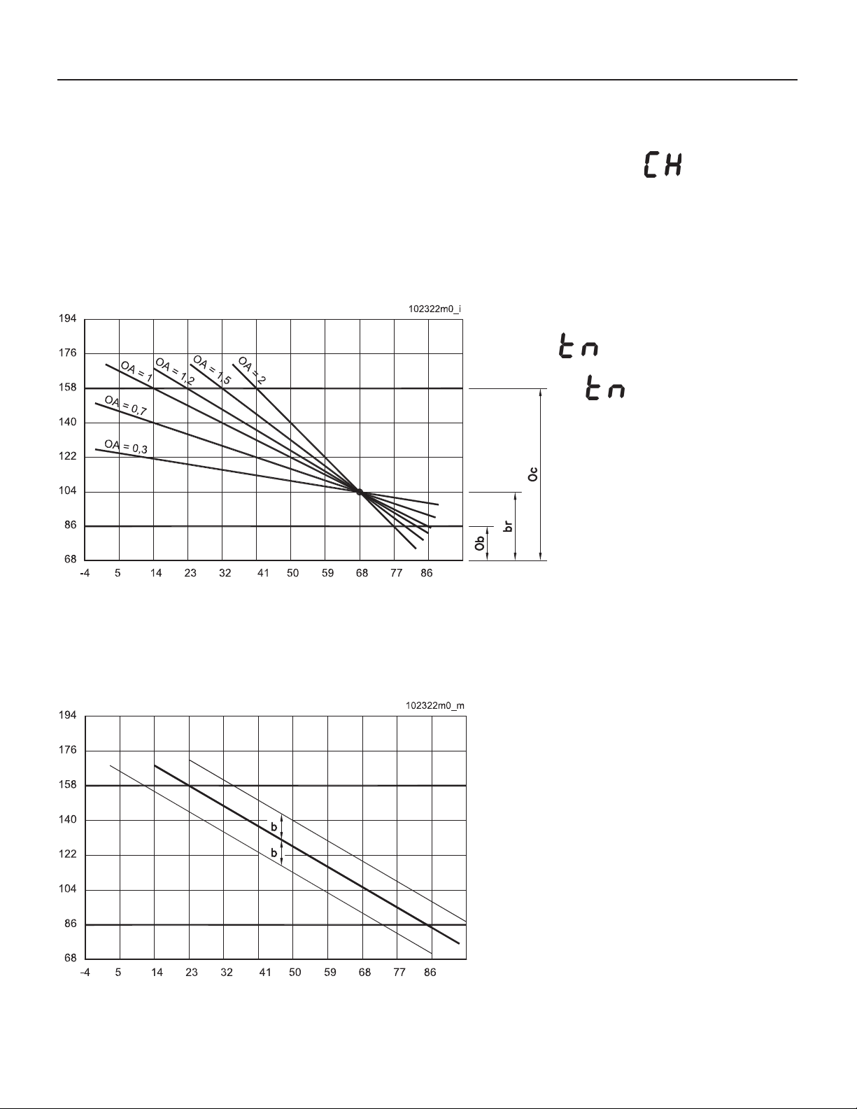
Calculated temperature (°F)
Outside temperature (°F)
Figure 13-2 - Graph of the outdoor reset adjustment
(infl uence of parameters “br”, “OA”, “Ob” and “Oc”)
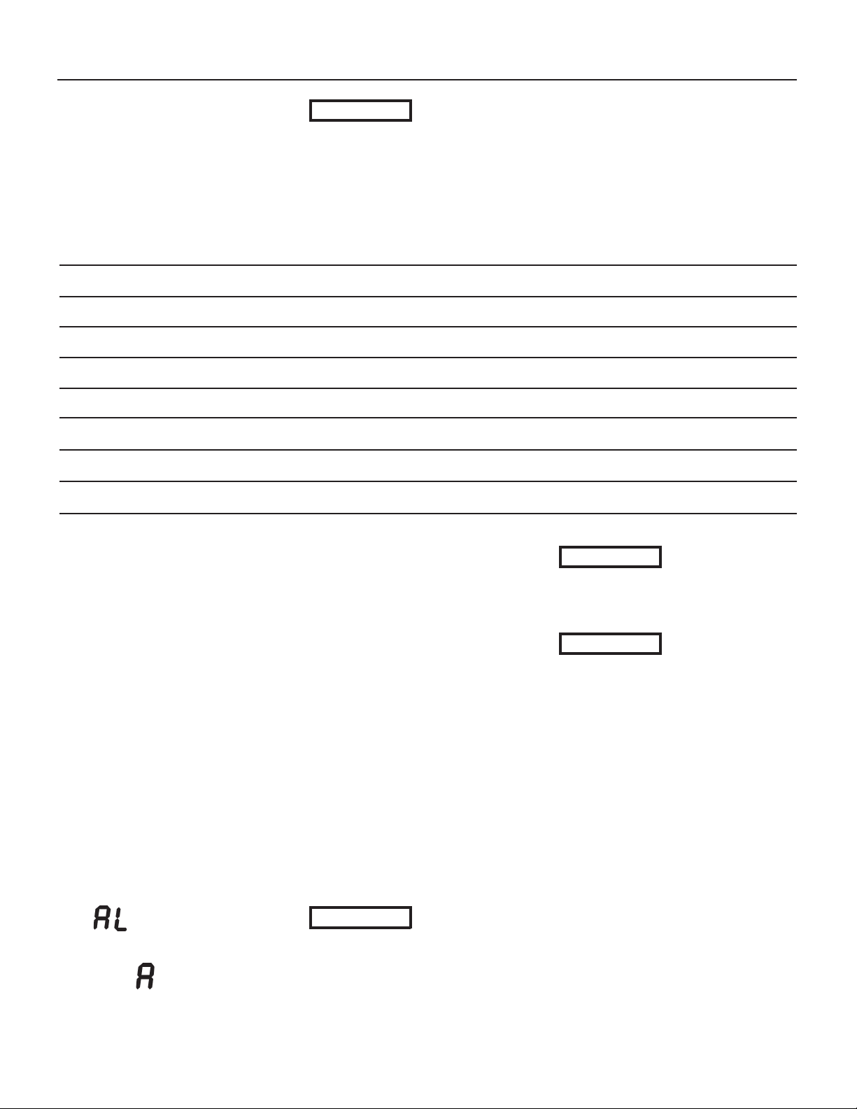
Calculated temperature (°F)
Outside temperature (°F)
Figure 13-3 - Graphs of the outdoor reset adjustment
(infl uence of parameter “b”)
V alues of this parameter that are
too high may translate into room
temperature instability . Values that are
too low may make the action of the
room thermostat ineffective.
Climatic adjustment with room
compensation can be used in all the
systems described in Section 13.10.1.
The advantage being that the constant
running of the pump will stabilize and
standardize the room temperatures.
This is especially true when some loops
in the heating system have considerably
greater volume than others.
OA = Slope of the line
Ob = Minimum heating
temperature
Oc = Maximum heating
temperature
br = “Fix point” of the angle
fulcrum of the line
b = parallel shift of the line
(adjusted by the heating
knob, item “7” of fi gure 13-1)
73
Page 2
13 - USE
13.11 - Boiler
switch settings
The control board shown in Figure
3-1, item “14”, contains a series of
switches that allow the boiler to be
confi gured to match the application.
The table below lists each switch and
its corresponding funtions.
SWITCH Position Description
1 OFF Boiler without production of D.H.W
ON Boiler with production of D.H.W. via storage tank
2 OFF Boiler with production of instantaneous D.H.W.
ON Position not available for this serie of boilers
3 OFF Heating pressure switch, disabled
ON Heating pressure switch, enabled
4 OFF EBM PAPST brand fan
ON Position not available for this serie of boilers
5 OFF Combination boiler for heating and D.H.W.
ON Boiler for heating only
6 OFF High temperature heating service, 86°F (30°C) to 176°F (80°C)
ON Low temperature heating service, 68°F (20°C) to 113°F (45°C)
7 OFF Boiler confi guration change, disabled
ON Boiler confi guration change, enabled
8 OFF Maximum heating supply water temperature of 176°F (80°C)
ON Position not available for this kind of boilers
CAUTION!!!
of these switches could cause the
boiler to malfunction resulting in
improper system performance.
Only a qualifi ed technician, with an
in-depth knowledge of the boilers’
control system, should change
them.
Improper setting
13.12 - Delays,
alarms and
protective actions
To protect the life of the appliance,
improve comfort, and maximize energy
savings, the following timings have
been incorporated into the control
logic:
a - Pump delay: each time the room
thermostat is satisfi ed, the circulator
pump continues to run for 1 minute;
b - DHW delay: each time the domestic
hot water demand is satisfi ed, a 2
minutes delay must pass before the
heating service is allowed to restart;
c - Protection against legionnaires
bacteria: if the boiler is connected
to a DHW storage tank the boiler
will increase the tank temperature
to 140 °F (60 °C) every seven days,
prevent the formation of legionnaires
bacteria. This function is displayed
by
d - DHW alarm: if the call for domestic
hot water lasts for longer than two
hours, an
This function is only for boilers set
up to provide instantaneous DHW.
.
01 alarm is generated.
e - Time delay in restarting the burner:
in its normal functioning state, except
when providing domestic water,
every time the burner stops, there is
a delay time of 3 minutes before the
boiler restarts again.
13.13 - Circulator
pump and three way
valve protection
During the summer months, the
circulator is run once a day for around
15 seconds to prevent it from seizing.
At the same time, the three way valve
(if present) is activated for the same
reason.
13.14 - Boiler’s
Freeze protection
CAUTION!!!
protection function to work, the
boiler must remain connected
to the electrical and gas
supplies with knobs “7” and
“11” in Figure 13-1, in the OFF
position.
For the freeze
CAUTION!!!
protection function is
conceived to protect the boiler
only, not the heating system.
CAUTION!!!
boiler’s freeze protection
function depends from the
electrical supply and from the
gas supply, it is mandatory
install a safety device that
alarm the user in a case
the boiler room will reach a
temperature near 35°F (2°C)
Once the boiler has reached a
temperature of 45 °F (7 °C), the
heating pump will automatically
comes on. If the temperature falls
below 35 °F (2 °C), the burner
will light to prevent the boiler from
freezing.
If the boiler will not be used for long
time it should be drained per Sections
14.10 and 14.11.
This freeze
Because the
74
Page 3
13 - USE
13.15 - Display
in energy saving
mode
If desired, the display, item “1” and
“2” in Figure 13-1, can be switched
permanently off, with the exception
of when it displays errors or settings.
To switch the display off, access the
“Installers’ Menu”, in section 13.17
and set the
other than zero. Keep in mind that
each value will correspond to a delay
in minutes until the display goes into
Energy Saving mode.
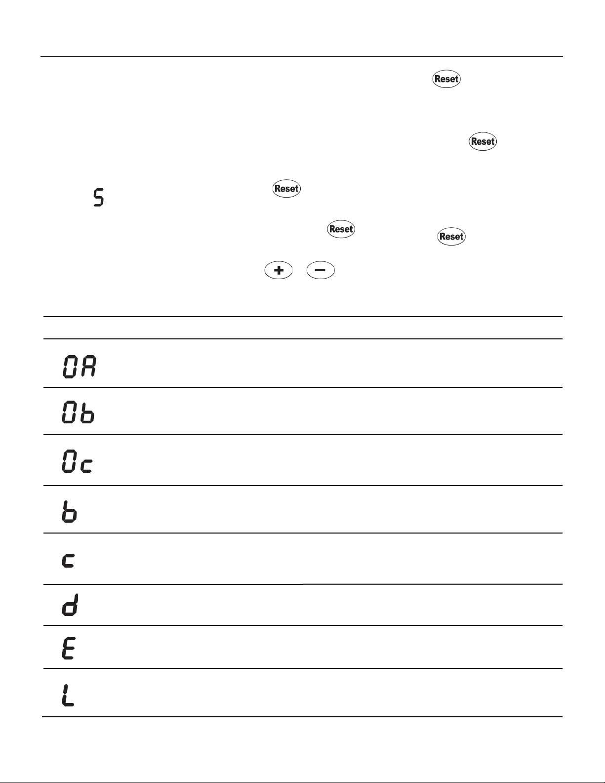
PARAMETER DESCRIPTION INFORMATION ON DISPLAY ITEM “2” of Figure 13-1
parameter at a value
Adjustment of the curve angel as shown in
Figure 13-2 when outdoor reset is active per
section 13.9.
13.16 - “Users’
menu”
When entering the “Users’ menu”, the
display, item “1” in Figure 13-1, will
start blinking indicating that a change
of mode has taken place. To access
the “Users’ menu” (see also Section
17 to better understand the several
menus):
1. press the button for 2
seconds until the display starts
blinking;
2. press and release the button
several times until the desired
parameter is displayed;
3. use the or keys, to
change the value of the selected
parameter;
Setting range: 0,1 to 5,0
4. press to save the parameter
change before going to the next
parameter.
When the last parameter has been
reached and the button
pressed, the display will stop blinking
indicating exit from the menu.
NOTE: If no key is pressed for
more than 60 seconds, the control
automatically exits the “Users’ menu”.
Any parameter change not saved
using the button, will be lost.
The table below lists each “Users’
menu” parameter, what it affects and
its adjustment range.
Adjustment of the “Minimum heating
temperature” as shown in Figure 13-2 when
outdoor reset is active per section 13.9.
Adjustment of the “Maximum heating
temperature” as shown in Figure 13-2 when
outdoor reset is active per section 13.9.
Adjustment of the parallel shift of the curve as
shown in Figure 13-3 when outdoor reset is
active per section 13.9.
Display of the calculated heating temperature
when outdoor reset is active per section 13.9,
or display of the temperature set by knob “7”
shown in Figure 13-1.
Display of the domestic hot water temperature
when set by knob “11” shown in Figure 13-1.
Display of last error code registered, Section
13.18.2
Setting range: see section 13.10.3
Setting range: see section 13.10.3
The adjustment is made by turning knob “7” shown
in Figure 13-1. The selected curve can be shifted
up or down by 36 °F (20 °C).
Temperature display only, with a range between 68
°F (20 °C) and 189 °F (87 °C).
Temperature display only with a range between 104
°F (40 °C) and 158 °F (70 °C), see section 13.7.
Error code display per section 13.18.2
Display of last lockout occurred, Section
13.18.1
Lockout code per section 13.18.1
75
Page 4
13 - USE
13.17 - “Installer’s
menu”
CAUTION!!!
parameters could cause the
boiler and therefore the system
to malfunction. For this reason,
only a qualifi ed technician who
has in-depth knowledge of the
boiler should change them.
The boiler’s micro-processor makes
this menu of parameters available
to the qualifi ed technician for the
analysis of the functioning and
adjustment of the appliance to the
system. When entering the “Installers’
Menu”, the display item “1” in Figure
13-1, will start to blink indicating that
a change of mode has taken place. To
access the “Installers’ Menu” just (see
also Section 17 to better understand
the several menus):
Changing these
1. press and hold the button
down for 12 seconds until the
parameter is displayed;
2. press and release the button
to scroll through the list of the
parameters;
3. once the parameter has been
displayed, it can be changed using
the or keys;
4. press and release the button
to confi rm the amended data before
moving to the next parameter.
When the last parameter has been
reached and the button
pressed, the display will stop blinking
indicating the exit from the menu.
NOTE: If no key is pressed for
more than 60 seconds, the control
automatically exits the “Installers’
menu”. Any parameter change not
saved using the button, will be
lost.
The next table lists each “Installers’
menu” parameter, what it affects and
its adjustment range.
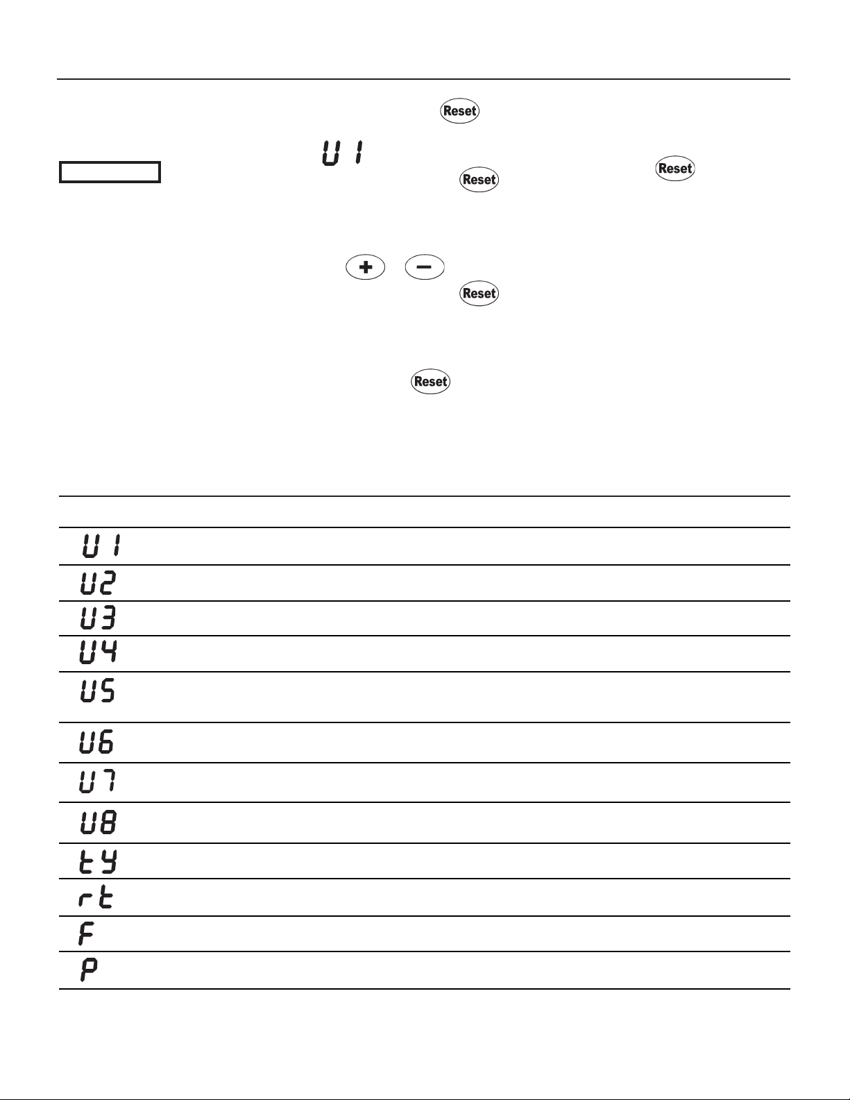
PARAMETER DESCRIPTION INFORMATION ON DISPLAY ITEM “2” OF FIGURE 13-1
Boiler temperature, measured by U1
sensor
DHW temperature, measured by U2
sensor
Domestic cold water (or ind. water heater)
temperature , measured by U3 sensor
Outdoor temperature, measured by U4
sensor
Ionization current value
High limit temperature, measured by U6
sensor
Flue gas temperature, measured by U7
sensor
Heating return temperature, measured
by U8 sensor
Type of basic setting of control board
Status of room thermostat contact
Value in °F (cannot be changed)
Value in °F (cannot be changed)
Value in °F (cannot be changed)
Value in °F (cannot be changed) (displayed only if outdoor reset is
active, as per section 13.9)
Value from 0 to 99 (cannot be changed)
(30 corresponds to a current of 1uA)
(99 corresponds to a current of 5.5 uA)
Value in °F (cannot be changed)
Value in °F (cannot be changed)
Value in °F (cannot be changed)
Can be changed in accordance with Section 11.6
00 = contact open (heating service off)
01 = contact closed (heating service on)
Measurement of fan speed rotation
BTU input for heating service
Value in g/1’/100 (rpm/100) (cannot be changed)
Adjustable according to the instructions of section 12.10
Continue
76
Page 5
13 - USE
Continued
PARAMETER DESCRIPTION INFORMATION ON DISPLAY ITEM “2” OF FIGURE 13-1
Can be changed (see Section 13.9):
Heating service functioning mode
00 = thermostatic adjustment;
01 = outdoor reset;
02 = outdoor reset with room compensation;
Reaction to external temperature
Angle fulcrum of climatic adjustment
Reduction of temperature generated by
the opening of the room thermostat
Boiler knobs’ status
Display “1” and “2” as per fi gure 13-1
energy saver
Parameter disabled for this kind of boiler
Domestic sensitivity setting
Minimum domestic setpoint during sleep
mode
Proportional band of the heating PID
modulation
Keep always at value of 1
Can be changed from 16°F (-9°C) to 149°F (65°C) (active only with
outdoor reset).
See section 13.10.3 for its adjustment.
Can be changed: from 1°F (1°C) to 36°F (20°C) (active only with
outdoor reset featuring room compensation)
See section 13.10.6 for its adjustment.
Can be changed:
01 = knobs presents;
00 = knobs absent.
Can be changed: 00 = display always on; any other value,
corresponds to a delay in the switching off of the display, expressed
in minutes (see also Section 13.15)
No infl uence in this kind of boiler
No infl uence in this kind of boiler
Must be maintained at 20 value
Integral of the heating PID modulation
Burner Anticycling: minimum delay from
a burner light-off to the sequent light-on.
Value expressed in sec x 10
Indirect water heater priority selection:
Value expressed in minutes.
Must be maintained at 40 value
Can be changed between 1 and 54. Default value is 18 (180 sec).
Can be modifi ed only in conjunction with factory technicians.
Can be changed between 00 (function disabled) and 99 minutes.
Default value is 00 (See also section 9.1.1).
77
Page 6
13 - USE
13.18 Diagnostics
During the normal operation of the
boiler, the display, of Figure 13-1,
continually shows the operating
status of the boiler as shown below
(see also section 17):
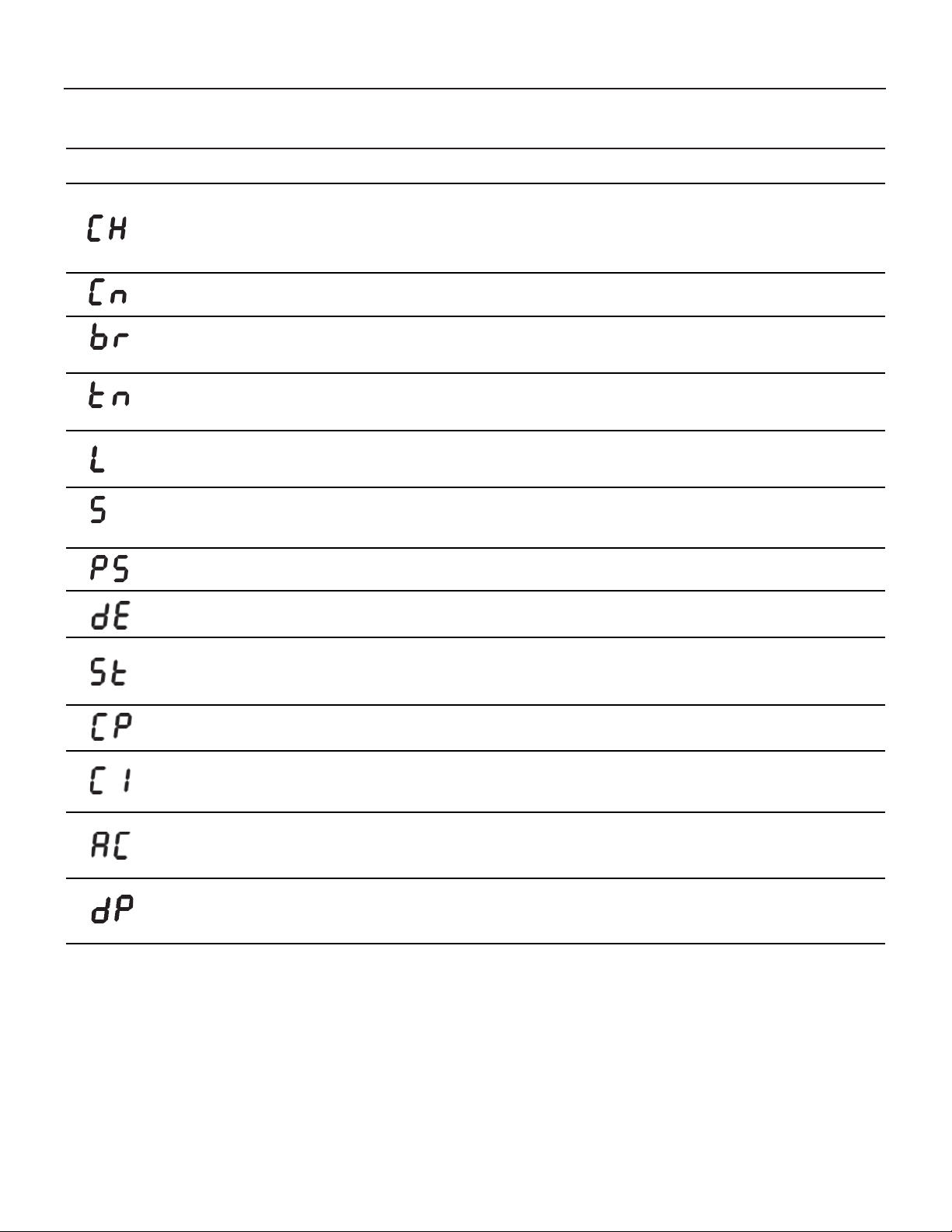
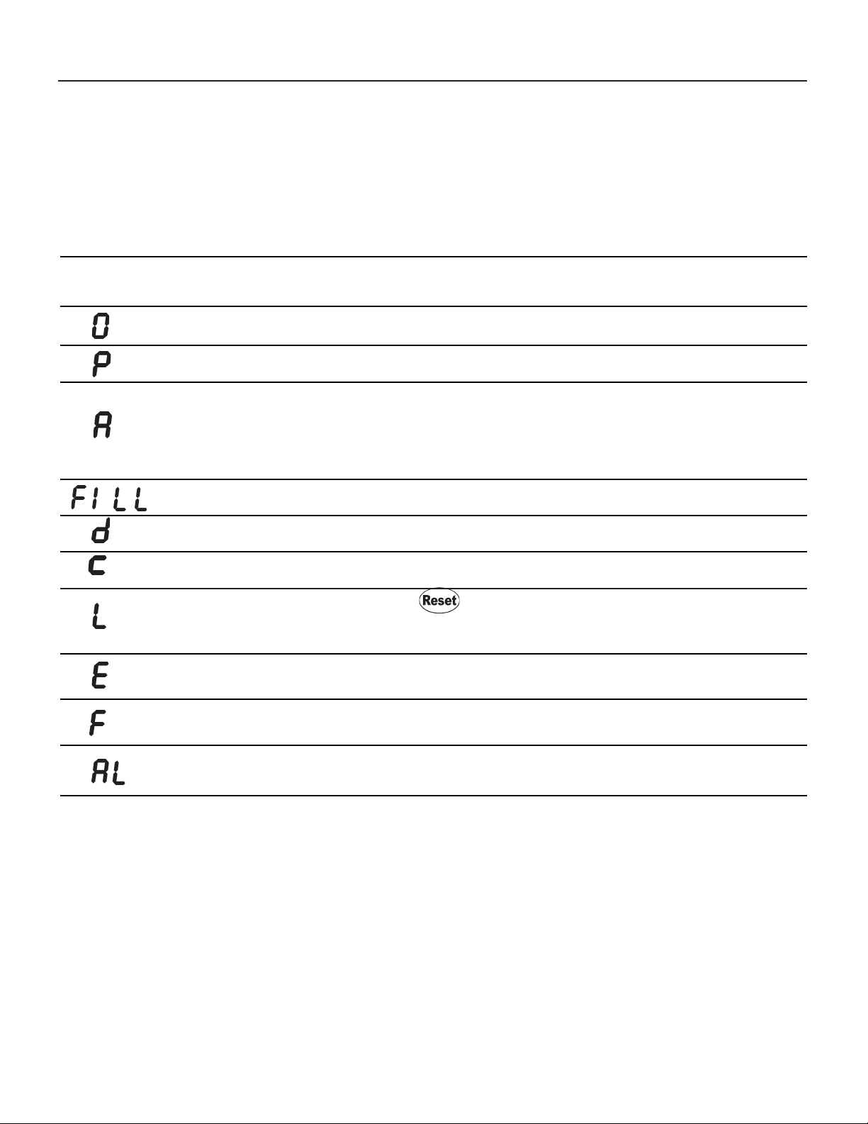
PARAMETER
PARAMETER REFERENCE DISPLAY READ OUT (ITEM “2”, FIGURE 13-1)
Boiler in stand-by mode or pause (no request for heating or
domestic hot water)
Anti-freeze function active
Boiler not in lock-out mode but in Attention mode.
System pressure too low, system must be fi lled. See section 13.1.
Domestic hot water service active
Heating service active
Boiler in lock-out mode. To reset it, press the
the lock-out occurs frequently, contact a professionally qualifi ed
technician
Blocking error. Contact a professionally qualifi ed technician. Blocking
errors automatically reset if the condition causing the block disappears
.
button. If
Boiler temperature (°F)
Boiler temperature (°F)
01 = Boiler temperature (°F) Domestic hot
water service active for more than 120
minutes. Turn domestic hot water to OFF
position to reinstate heating.
02 = Data connection interrupted between
cascade boilers
No display
Domestic hot water temperature (°F)
Heating temperature (°F)
Lock-out code (see section 13.18.1 for
decodifi cation).
Error code (see section 13.18.2 for
decodifi cation).
Auto-purging procedure that last 3 minutes in progress (see
section 13.4).
Boiler in Anti-legionella functioning (see section 13.12)
78
Boiler temperature (°F)
Storage tank temperature (°F)
Page 7

13 - USE
13.18.1 - Diagnostics: “L” lock-outs
“L”
Code
L01
L02
L03
L04
L05
L06
Lock-out
description
No fl ame detected after
three ignition attempts.
Flame extinguishes three
times.
Boiler temperature is over
203° F (95°C).
Gas valve command relay
Safety relay
Flue gas sensor over
210°F (99°C)
Checks to make
Check:
a-correct gas supply pressure (see
section 12.7);
b-ignition spark (see section 14.4);
c-correct combustion air pressure (see
section 12.8);
d-120Vac at the gas valve;
e-resistance of the two gas valve coils
should be 0.18 kohm and 1.1 kohm;
f- If the burner lights, but goes out at the
end of the ignition attempt, check: that
the ionization current is set at a value
greater than 60 (follow procedure in
section 14.12.4)
Check:
a-that the ionization current is set
at a value greater than 60 (follow
procedure in section 14.12.4);
b-check that gas valve open fast
enough;
a-Check that the circulator pump is
working;
b-Check if the water fl ow is not less than
5 GPM
Check for correct polarity of the wires to
the pump. Try to switch the wires.
Check:
a - that the electrical resistance of the
fl ue gas sensor complies with the graph
in Section 14.13;
b - that the effi ciency of the boiler is
over 86%
Solutions
a-If the gas supply pressure is incorrect, it must be adjusted to
the correct pressure;
b-If spark is not present, check for correct ignition ectrode
position and gap as per section 14.4; If position is correct,
check for 120Vac at the supply of the spark generator.
c-if the combustion air pressure is incorrect, inspect the vent
system and eliminate any obstructions;
d-if the voltage to the gas valve is not 120Vac the power control
board must be replaced;
e-if the resitance of the gas valve coils is not 0.18 kohm and/or
1.10 kohm, the gas valve must be replaced.
f-If the ionization current is not greater than 60, confi rm that
the the CO2 content is adjusted properly (see section
12.9). Check the fl ame detection electrode (section 14.4)
and if necessary replace it, check the integrity of the fl ame
detection electrode electrical wires.
a-If the ionization current is not greater than 60, confi rm that
the the CO2 content is adjusted properly (see section
12.9). Check the fl ame detection electrode (section 14.4)
and if necessary replace it, check the integrity of the fl ame
detection electrode electrical wires.
b-Following procedure as per Section 14.12.4, check few times
if passing from low fi re to high fi re the fl ame estinguish. If
estinguish, change the gas valve.
a-If the circulator pump is bad, replace it, if is good, replace the
power control board.
b-If the water fl ow is less than 5 GPM check for any zone
valves that must be opened.
Replace the power control board
If the pump won’t run replace it. If the pump is good try to
replace the power control board.
a-If the fl ue gas sensor resistance does not correspond with the
correct values, replace it;
b-if the boiler effi ciency is less than 86% and the CO2 content
is correct, the primary heat exchanger has to be replaced
and proper water treatment methods employed to prevent
mineral build up on the water side
L07
L08
L09
L10
L12
L13
L14
L15
L16
L17
Electrical circuit of fl ue
gas sensor is interrupted
Spark generator relay
RAM memory
E2prom memory damaged
E2prom memory damaged
Program error
Program error
Program error
Program error
The temperature
difference between the
U1 and U6 sensors is too
great
Check that the electrical resistance of
the fl ue gas sensor corresponds with the
graph in section 14.13;
Check that:
a - the electrical resistance of the two
sensors corresponds with the graph in
section 14.13;
b -check that the heating water fl ow is
not too low.
79
If the sensor resistance does not correspond with the correct
values, replace it;
Replace the power control board
Replace the power control board
Replace the power control board
Replace the power control board
Replace the power control board
Replace the power control board
Replace the power control board
Replace the power control board
a-If one or both sensors does not have the correct resistance
value, it must be replaced;
b-If temperature difference between U1 and U8 is higher than
55°F at maximum input, the heating water fl ow rate is too
low. The heating water fl ow rate must be corrected.
Page 8

13 - USE
13.18.1 - Diagnostics: “L” lock-outs (continued)
“L”
Code
L18
L19
L20
L21
L25
L32
L33
L45
L46
Lock-out
description
Program error
Flame sensed for 10
seconds, after the closure
of the gas valve
Flame sensed before
opening of the gas valve.
Boiler in blocking state for
more than 20 hours
U1 or U6 sensor increase
its temperature too fast
Program error
Fan rotation error
Heating circuit fi lling time
longer than 10 minutes.
Filling of heating circuit
repeated 16 times in 24
hours
Controls
Check:
a - that the heating water fl ow is not too
low;
b - that the circulator pump is working
Check that the voltage to the fan is
163(±10)Vdc.
Check:
a - that the heating pressure switch
setting pressure, FILL appears when
the pressure drops below 8.7 psi
(0,6 bar), and disappears when the
pressure rises above 22 psi (1.5
bar);
b - check that there are no water leaks
in the heating system.
Solutions
Replace the power control board
Call technical service
Call technical service
Press RESET button and check the blocking error “E” on
Section 13.18.2
a - If temperature difference between U1 and U8 is higher than
55°F (31°C), at maximum input, the heating water fl ow rate
is too low. The heating water fl ow rate must be corrected.
b - If the pump works, replace the power control board.
Replace the power control board
If the fan is powered with 163Vdc, replace the fan. If the voltage
to the fan is not 163 Vdc, replace the board.
a -If the heating pressure switch is not correctly set, it must be
replaced;
b - if the system has a leak, it must be fi xed.
L47
Flue pressure switch
open time longer than 60
minutes
Check:
a - that no obstructions are in the fl ue
discharge/air intake line
b - check the fl ue pressure switch
setting point, setting is 4.5 in.W.C
c - check that the electrical resistance of
the fl ue gas sensor corresponds with
the graph in section 14.13;
d - check that the electrical connection
cables between the fl ue pressure
switch, the fl ue sensor and the
power control board.
a -If ther’is an obstruction, it must be removed;
b - If the fl ue pressure switch is not correctly set, it must be
replaced;
c - If the fl ue sensor resistance does not correspond, it must be
replaced;
d - if the electrical circuit is damaged, it must be repaired;
if the previous four cases do not apply, replace the power
control board
80
Page 9

13 - USE
13.18.2 - Diagnostics: “E” blocking errors
“E”
Code
E01
E02
E04
E07
Blocking
description
U1 boiler temperature
sensor circuit interrupted.
U2 domestic hot water
temperature sensor circuit
interrupted.
U8 return temperature
sensor circuit interrupted
U3 cold water or indirect
water heater sensor circuit
interrupted
Checks to make
Check that the electrical resistance of
the sensor corresponds with the graph in
section 14.13;
check that the electrical connection cables
between the sensor and the power control
board have continuity and carry current
Check that the electrical resistance of
the sensor corresponds with the graph in
section 14.13;
check that the electrical connection cables
between the sensor and the power control
board have continuity and carry current
Check that the electrical resistance of
the sensor corresponds with the graph in
section 14.13;
check that the electrical connection cables
between the sensor and the power control
board have continuity and carry current
Check that the electrical resistance of
the sensor corresponds with the graph in
section 14.13;
check that the electrical connection cables
between the sensor and the power control
board have continuity and carry current
Solutions
If the sensor resistance does not correspond, it must be
replaced;
if the electrical circuit is damaged, it must be repaired;
if the previous two cases do not apply, replace the power
control board
If the sensor resistance does not correspond, it must be
replaced;
if the electrical circuit is damaged, it must be repaired;
if the previous two cases do not apply, replace the power
control board
If the sensor resistance does not correspond, it must be
replaced;
if the electrical circuit is damaged, it must be repaired;
if the previous two cases do not apply, replace the power
control board
If the sensor resistance does not correspond, it must be
replaced;
if the electrical circuit is damaged, it must be repaired;
if the previous two cases do not apply, replace the power
control board
E08
E11
E12
E13
U6 boiler temperature
sensor circuit interrupted.
U1 boiler temperature
sensor circuit shortcircuited.
U2 domestic hot water
temperature sensor circuit
short-circuited
Erroneous temperature
reading.
Check that the electrical resistance of
the sensor corresponds with the graph in
section 14.13;
check that the electrical connection cables
between the sensor and the power control
board have continuity and carry current
Check that the electrical resistance of
the sensor corresponds with the graph in
section 14.13;
check that the electrical connection cables
between the sensor and the power control
board have continuity and carry current
Check that the electrical resistance of
the sensor corresponds with the graph in
section 14.13;
check that the electrical connection cables
between the sensor and the power control
board have continuity and carry current
If the sensor resistance does not correspond, it must be
replaced;
if the electrical circuit is damaged, it must be repaired;
if the previous two cases do not apply, replace the power
control board
If the sensor resistance does not correspond, it must be
replaced;
if the electrical circuit is damaged, it must be repaired;
if the previous two cases do not apply, replace the power
control board
If the sensor resistance does not correspond, it must be
replaced;
if the electrical circuit is damaged, it must be repaired;
if the previous two cases do not apply, replace the power
control board
Replace the power control board
81
Page 10

13 - USE
13.18.2 - Diagnostics: “E” blocking errors (continued)
“E”
Code
E14
E15
E16
E17
E18
E19
E20
E21
E22
E23
E30
Blocking
description
U8 return temperature
sensor short-circuited
U4 outside sensor shortcircuited
Erroneous temperature
reading.
U3 cold water temperature
or indirect water heater
temperature sensor circuit
shorted
U6 boiler temperature
sensor circuit shorted
E2prom memory damaged
Flame presence with gas
valve closed
Phase and neutral inverted
Electrical supply frequency
other than 60Hz
Ground connection is
absent
Erroneous temperature
reading.
Checks to make
Check that the electrical resistance of
the sensor corresponds with the graph in
section 14.13;
check that the electrical connection cables
between the sensor and the power control
board have continuity and carry current
Check that the electrical resistance of
the sensor corresponds with the graph in
section 14.14;
check that the electrical connection cables
between the sensor and the power control
board have continuity and carry current
Check that the electrical resistance of
the sensor corresponds with the graph in
section 14.13;
check that the electrical connection cables
between the sensor and the power control
board have continuity and carry current
Check that the electrical resistance of
the sensor corresponds with the graph in
section 14.13;
check that the electrical connection cables
between the sensor and the power control
board have continuity and carry current
Invert phase and neutral
Check the electrical frequency of the
system.
Check if CS parameter is at 03 (see
section 17)
Check if the boiler is properly grounded
Solutions
If the sensor resistance does not correspond, it must be
replaced;
if the electrical circuit is damaged, it must be repaired;
if the previous two cases do not apply, replace the power
control board
If the sensor resistance does not correspond, it must be
replaced;
if the electrical circuit is damaged, it must be repaired;
if the previous two cases do not apply, replace the power
control board
Replace the power control board
If the sensor resistance does not correspond, it must be
replaced;
if the electrical circuit is damaged, it must be repaired;
if the previous two cases do not apply, replace the power
control board
If the sensor resistance does not correspond, it must be
replaced;
if the electrical circuit is damaged, it must be repaired;
if the previous two cases do not apply, replace the power
control board
Replace the command and control board
Replace the gas valve
If phase and neutral are correctly wired, replace the power and
control board
If the electrical supply frequency is other than 60Hz, contact
the electric company;
if the mains frequency is 60Hz, replace the command and
control board.
Make sure that the CS parameter is at 03.
if the boiler is properly grounded, replace the power control
board
Replace the power control board
E31
E32
E33
E42
E50
E51
E52
E53
Erroneous temperature
reading.
Erroneous temperature
reading.
Erroneous temperature
reading.
Program error
Error in the boiler tY
parameter selection
Reset button pressed too
often in a short period time
Heating fl ow switch
closed
Heating fl ow switch
open
Move ON switches 7 an set again the
correct tY value (see section 17)
Check if the heating pump is running.
Check if the fl ow switch contact is stuck
Check if the heating pump is running.
Check if the fl ow switch contact is
broken
82
Replace the power control board
Replace the power control board
Replace the power control board
Replace the power control board
If tY value is correct, change the power control board
The pump should not run and the contanct should open
The contact must be open
The pump should run and the contact should closed
The contact must be closed
Page 11
14 - MAINTENANCE
14.1 - Care and
maintenance
This section must be brought to the attention
of the user by the installer so that the user
can make the necessary arrangements with
a qualifi ed service agency for the periodic
care and maintenance of the boiler. User
must check its boiler follow Table 14-1
column “User maintenance”.
The installer must also inform the user that
the lack of proper care and maintenance of
this boiler and any fuel burning equipment
may result in a hazardous condition.
Installer should discuss contents of the
Section 13 (User’s section) with the user.
Service and maintenance schedules
Service Technician User maintenance
Annual Startup:
A trained and qualifi ed service technician
should perform the inspection listed in these
instructions before each heating season and
at regular intervals.
WARNING!!!
inspection and adjustment must
be done by a trained technician
in accordance with all applicable
local and national codes. Improper
servicing or adjustment could
damage the boiler! Failure to
comply with this warning can
result in a fi re or explosion
causing property damage,
personal injury or loss of life!
Servicing,
Daily:
WARNING!!!
combustible materials, gasoline or
any product containing fl ammable
vapors and liquids in the vicinity
of the boiler. Failure to comply
with this warning can result in
extensive property damage, severe
personal injury or death!
Never store
- Address reported problems (Follow section 14.1.1);
- Check all piping for leaks (Follow section 14.1.2)
- Verify fl ue and air lines in good condition and
sealed tight (Follow section 14.1.3);
- Check system water pressure/system piping/
expansion tank (Follow section 14.1.4);
- Check control settings (Follow section 14.1.5);
- Check ignition and fl ame sense electrodes (Follow
section 14.1.6);
- Check wiring and connections (Follow section
14.1.7);
- Perform performance verifi cation (Follow section
14.1.8);
- Flame inspection (Follow section 14.1.9);
- Check fl ame signal (Follow section 14.1.10);
- Clean the heat exchanger if fl ue temperature
is more than 72°F (40°C) above return water
temperature (Follow section 14.3).
- Clean condensate trap (Follow section 14.5).
- Check combustion air pressure (Follow section
12.8).
- Check relief valve (Follow section 14.1.11);
- Check for any air inside the domestic heat
exchanger (Follow section 12.1.4);
- Check any domestic water softener if need any
maintenance (follow softener’s manufacturer
instructions)
- Check boiler area (Follow section 14.1.12);
- Check pressure gauge (Follow section 14.1.13);
Monthly:
- Check vent piping (Follow section 14.1.14);
- Check air piping (Follow section 14.1.15);
- Check condensate drain system (Follow section
14.1.16);
Every six month:
- Check boiler piping (gas and water) for leaks
(Follow section 14.1.17);
End of season months:
- Shut boiler down (unless boiler used for domestic
hot water) (Follow section 14.1.18);
Table 14-1 - Service and Maintenance Schedules
83
Page 12

14 - MAINTENANCE
WARNING!!!
obstruct the fl ow of combustion
and ventilation air. Failure to
provide adequate combustion
air for this boiler can result
in excessive levels of carbon
monoxide which can result in
severe personal injury or death!
WARNING!!!
maintenance is performed on
the vent-air intake system it
must be properly reassembled
and sealed. Failure to properly
maintain the vent-air system
can result in excessive levels
of carbon monoxide which can
result in severe personal injury
or death!
WARNING!!!
performing any maintenance
operations, shut the boiler
off, close the manual gas
shut-off valve (Figure 11-1)
and shut off electrical power
to the boiler. Follow the
Operating Instructions outlined
in the section “SAFETY
INSTRUCTIONS” (Beginning of
the manual).
Never
If
Before
14.1.1 - Address reported
problems
Inspect any problems reported by the
owner and correct before proceeding.
14.1.2 - Check all piping
for leaks
CAUTION!!!
or boiler leaks. Continual fresh
makeup water will reduce boiler
life. Minerals can build up in
sections, reducing heat transfer,
overheating heat exchanger,
and causing heat exchanger
failure. Leaking water may also
cause severe property damage.
1. Inspect all water and gas piping and
verify to be leak free.
2. Look for signs of leaking lines and
correct any problems found.
Eliminate all system
3. Check for gas leaks: using soap
solution, check for gas leaks from
meter to boiler including all pipes and
fi ttings and boier connections. Use
liquid soap solution for all gas testing.
WARNING!!!
check for gas leaks with an
open fl ame. Use the bubble
test. Failure to use the bubble
test or check for gas leaks
with an open fl ame can cause
explosion, severe personal
injury, death, or substantial
property damage.
Do not
14.1.3 - Verify fl ue and air
lines in good condition
and sealed tight;
1. Check for obstruction, condensation,
corrosion and physical damage,
water stains, any signs of rust, other
corrosions or separation of the vent
and air intake piping.
2. Check outside terminations. Screens
and louvers should be free of any
debris and must be cleaned as
required.
14.1.4 - Check system
water pressure/system
piping/expansion tank;
1. Check water piping and accessories
for leaks. Slightest leaks should be
corrected.
2. Check the system to be full of water
and pressure to remain stable at
correct setting on gauge.
14.1.5 - Check control
settings
1. Thermostat Test (control knobs items
“7” and “11”, Figure 13-1): Set knobs
setting to low enough to end call for
heat. Gas valve should close and
burner should stop fi ring. Fan go into
a post purge, then shuts off.
2. Control Safety Shutdown test: with
the burner fi ring, close the manual
gas shut off valve (Figure 11-1) .
Gas valve should close and burner
should stop fi ring. The boiler will try
for ignition three times after this,
then should lock out with an “L 01”
error shown on the display. Open the
manual gas shut-off valve, and press
the “Reset” button to return to normal
operation.
84
14.1.6 - Check ignition and
fl ame sense electrodes
1. Remove the fan-burner assembly
unit (see section 14.3)
2. Remove any deposits accumulated
on the ignition/fl ame sense electrode
using sand paper.
3. Check electrodes positioning meet
Section 14.4
14.1.7 - Check wiring and
connections
Inspect all boiler wiring, making
sure wires are in good condition and
securely attached.
14.1.8 - Perform
performance verifi cation.
1. Start boiler and perform a
combustion test as per section 12.9.
2. Verify cold fi ll pressure is correct and
that operating pressure does not go
too high (could be a problem on the
expansion tank).
14.1.9 - Flame inspection
1. Inspect fl ame through observation
window.
2. If the fl ame is unsatisfactory at either
high fi re or low fi re, clean the burner
following section 14.3.
14.1.10 - Check fl ame
signal
1. Follow section 14.12.4 to check the
fl ame signal.
2. At high fi re and low fi re the fl ame
signal shown on the display should
be within values given in Section 15,
header “ionisation current”. A lower
fl ame signal may indicate a fouled or
damaged fl ame sense electrode. If
cleaning the fl ame sense electrode
does not improve, ground wiring
is in good condition, and ground
continuity is satisfactory, replace the
fl ame sense electrode.
14.1.11 - Check relief valve
Inspect the relief valve and lift the lever
to verify fl ow. Before operating any
relief valve, ensure that it is piped with
its discharge in a safe area to avoid
severe scald potential. Read Section
7.2.2 before proceeding further. Relief
vavle should be re-inspected at least
once every three years, by a licensed
Page 13

14 - MAINTENANCE
plumbing contractor or authorized
inspection agency, to ensure that
the product has not been affected
by corrosive water conditions and to
ensure that the valve and discharge line
have not been altered or tampered with
illegally.
Certain naturally occurring conditions
may corrode the valve or its
components over time, rendering the
valve inoperative. Such conditions are
not detectable unless the valve and its
components are physically removed
and inspected. This inspection must
only be conducted by a plumbing
contractor or authorized inspection
agency – not by the user.
WARNING!!!
re-inspect the boiler relief valve
as directed could result in unsafe
pressure buildup, which can result
in severe personal injury, death, or
substantial property damage.
Failure to
14.1.12 - Check boiler area
WARNING!!!
potential of severe personal
injury, death, or substantial
property damage, eliminate
all materials discussed below
from the boiler vicinity and the
vicinity of the boiler combustion
air inlet.
If contaminants are found:
Remove products immediately
from the area. If they have
been there for an extended
period, call a qualifi ed service
technician to inspect the boiler
for possible damage from acid
corrosion.
If products cannot be removed,
immediately call a qualifi ed
service technician to re-pipe
vent and air piping and locate
vent termination/air intake away
from contaminated areas.
1. Combustible/fl ammable materials --
Do not store combustible materials,
gasoline or any other fl ammable
vapors or liquids near the boiler.
Remove immediately if found.
To prevent
2. Air contaminants -- Products
containing chlorine or fl uorine,
if allowed to contaminate the
boiler intake air, will cause acidic
condensate in the boiler. This will
cause signifi cant damage to the
boiler if allowed to continue. Read
the list of potential materials listed in
Section 10.2. If any of these products
are in the room from which the boiler
takes its combustion air, they must
be removed immediately or the boiler
combustion air (and vent termination)
must be relocated to another area.
14.1.13 - Check pressure
gauge
1. Make sure the pressure reading
on the boiler pressure gauge does
not exceed 25 psi. Higher pressure
may indicate a problem with the
expansion tank.
2. Contact a qualifi ed service technician
if problem persists.
14.1.14 - Check vent
piping
1. Visually inspect the fl ue gas vent
piping for any signs of blockage,
leakage, or deterioration of the
piping. Notify your qualifi ed service
technician at once if you fi nd any
problems.
WARNING!!!
to inspect the vent system
as noted above and have it
repaired by a qualifi ed service
technician can result in vent
system failure, causing severe
personal injury or death.
Failure
14.1.15 - Check air piping
1. Visually inspect the air inlet
termination to be sure it is
unobstructed. Inspect the entire
length of air piping to ensure piping
is intact and all joints are properly
sealed.
2. Call your qualifi ed service technician
if you notice any problems.
14.1.16 - Check
condensate drain system
1. Inspect the condensate drain line,
condensate fi ttings and condensate
trap for signs of weeping or leakage.
2. If you detect signs of leakage,
immediately contact your qualifi ed
service technician to inspect the
boiler and system.
14.1.17 - Check boiler
piping (gas and water)
1. If gas odor or leak is detected,
immediately shut down the boiler
following the procedures on page 3.
Call a qualifi ed service technician.
2. Visually inspect for leaks around
water piping. Also inspect the
circulators, relief valve, and fi ttings.
Immediately call a qualifi ed service
technician to repair any leaks.
WARNING!!!
fi xed at once by a qualifi ed
service technician. Failure to
comply could result in severe
personal injury, death, or
substantial property damage.
Have leaks
14.1.18 - Shut boiler down
(unless boiler is used for
Domestic Water)
1. Follow “To Turn Off Gas to Appliance”
on page 3 of this manual.
2. Do not drain the system unless
exposure to freezing temperatures
will occur.
3. Do not drain the system if it is fi lled
with an antifreeze solution.
4. DO NOT shut down boilers used for
domestic water heating, they must
operate year-round.
85
Page 14

14 - MAINTENANCE
14.2 - Removing the
casing
In order to remove the casing, follow
the steps below while refering to
Figure 14-1:
1. remove screws “A”;
2. raise latch “C”;
3. remove the front cover;
4. press the two plastic springs, item
“L”, down;
5. lower the electrical box;
6. lift latch “G”;
7. pull the bottom of cover “H” out by
around 4 in (10 cm);
8. lift cover “H” up by around 1in (2
cm) and remove it.
Figure 14-1 Removing the casing
86
Page 15

14 - MAINTENANCE
14.3 - Cleaning the
burner and primary
heat exchanger,
fl ue gas side
Burner and primary heat exchanger
must be checked every year and
cleaned if required. To correctly clean
the burner and the fl ue gas side of
the heat exchanger follow the steps
below:
WARNING!!!
proceeding to the next step,
verify that the electrical supply
to the boiler, and any other
electrical supply near the
boiler, is off. Failure to comply
with this warning can cause
extensive property damage,
severe personal injury or
death!
1. follow the steps in Section 14.2
to gain access to the sealing
chamber;
2. unscrew nut “D” (Figure 14-2) from
the gas valve (taking care not to
lose gasket “E” in Figure 14-4);
3. disconnect the two wires from the
ignition electrodes and the wire
from the fl ame detection electrode,
Figure 3-1, details “47” and “50”;
4. disconnect the wire from safety
sensor “F” in Figure 14-2;
5. unscrew the four nuts “C” in Figure
14-2;
Before
6. prepare a suitable cover for the
gas valve outlet under nut “D” so
that no dirt, water, or other foreign
objects can fall into the gas valve
during cleaning;
7. remove the entire fan - burner
assembly, detail “A” in Figure 14-2;
8. use a cylindrical brush with plastic
bristles to clean the inside of the
combustion chamber, detail “H” in
Figure 14-2;
9. use a vacuum cleaner to remove
any unburned residue from the
combustion chamber “H” in fi gure
14-2;
10. using the same vacuum cleaner,
clean the surfaces of the burner
and around the electrodes;
WARNING!!!
performing the next step,
carefully wash only the inside
of the combustion chamber
“H” of Figure 14-2, and do not
get water on the outside of the
combustion chamber opening.
Failure to comply with this
warning can cause extensive
property damage, severe
personal injury or death!
while
11. using only water, wash the inside
of the combustion chamber, detail
“H” in Figure 14-2. The water, will
drain into the condensate drain.
Clean the condensate trap (see
Section 14.6) before reassembling
components;
12. reassemble the components by
proceeding in reverse order;
13. open the manual gas shutoff
valve;
14. restore electrical power to the
boiler;
15. check that there are no gas leaks.
WARNING!!!
an open fl ame to test for gas
leaks. Always use an approved
leak detection method. Failure
to comply with this warning
can cause extensive property
damage, severe personal injury
or death!
Never use
Figure 14-2 Remove the fan-burner assembly unit
87
Page 16

14 - MAINTENANCE
14.4 - Correct
positioning of
the ignition and
fl ame detection
electrodes
For the boiler to work properly the
electrodes must be positioned as
shown in Figure 14-3:
the distance between the ignition
electrodes “A” and “B”, must be
between 0.08 in (2 mm), and 0.10
in (2.5 mm);
the distance of the ignition
electrodes to the burner surface
must be between 0.20 in (5.0 mm),
and 0.22 in (5.5 mm);
the distance of the fl ame detection
electrode to the burner surface
must be between 0.23 in (6.0 mm),
and 0.27 in (7.0 mm).
A = Left ignition electrode
B = Right ignition electrode
C = Flame detection electrode
Figure 14-3 Positioning electrodes on burner
(Use a hand caliper to verify the distances of the
electrodes)
NOTE: To insure correct
functioning of boiler the distances
listed above shall be verifi ed with a
hand caliper.
14.5 - Domestic
hot water heat
exchanger (only for
160-C model)
The production of DHW takes place
in the secondary heat exchanger,
detail “42” in Figure 3-1. If this heat
exchanger loses effi ciency over
time, it may be necessary to clean or
replace it.
88
Page 17

14 - MAINTENANCE
14.6 - Condensate
trap cleaning
The condensate trap must be checked
every year and cleaned if required.
Follow the steps below to properly
clean the condensate trap and its
associated components while referring
to Figure 14-4:
1. turn the power switch to on, item
“12” in Figure 13-1;
2. press the and keys
together for more than 10 seconds,
until a blinking is displayed;
3. the combustion blower will run at
maximum speed for 10 minutes.
During this time the burner will not
light. This will minimize the amount
of liquid present in the trap, item
“A”;
4. press the button
WARNING!!!
proceeding to the next step,
verify that the electrical supply
to the boiler, and any other
electrical supply near the
boiler, is off. Failure to comply
with this warning can cause
extensive property damage,
severe personal injury or death!
5. follow the steps in Section 14.2
to gain access the internal
components;
6. carefully cover the electrical panel
“B” with a waterproof material to
prevent water from entering the
electrical system;
7. grip spring clamp “G” with a pair of
pliers and slide it downwards;
8. pull the condensation trap hose “H”
off the trap;
9. remove the fan-burner assembly
unit, follow steps of section 14.3;
10. cover the gas valve outlet
to ensure that no objects or
condensate water enters the gas
valve;
11. disconnect the condensate hose
“O” from the condensate trap “A”.
12. unscrew nut “I” from the bottom of
the trap, “A”, and pull it upwards,
taking care not to spill the
condensation;
13. open the condensate trap taking
care not to lose o ring “L” and clean
the inside “M”;
14. re-assemble everything in reverse
order, taking care that oring “L” is
placed in the proper location;
15. refi ll the condensate trap per
Section 12.1.2.
16. open the manual gas shutoff valve;
17. restore electrical power to the
boiler;
18. check that there are no gas leaks.
Before
Figure 14-4 Removing the condensing trap
89
WARNING!!!
an open fl ame to test for gas
leaks. Always use an approved
leak detection method. Failure
to comply with this warning
can cause extensive property
damage, severe personal injury
or death!
Never use
Page 18

14 - MAINTENANCE
Figure 14-5 Replacing the pump motor (only for 160-C
model)
14.7 - Circulator
pump motor
replacement (only
for 160-C model)
To replace the circulator pump follow
the steps below while, refering to
Figure 14-5:
1. follow the steps in Section 14.10 to
isolate and drain the water from the
boiler;
2. follow the steps in Section 14.2
to gain access the internal
components;
3. remove screws “B”;
4. remove the circulator pump motor
“A”;
5. label the electrical wires of the
circulator pump motor, phase and
neutral must be respected;
6. disconnect the electrical wires from
the circulator pump motor
7. install the new circulator pump
motor and reassemble the boiler
8. open the heating system isolation
valves and heating system fi ll valve
9. follow the steps in Section 12.1.3
to bleed the air from the heating
system.
NOTE: If display shows L05 reverse
polarity (phase and neutral) to the
pump
90
14.8 - Expansion
tank pressure (only
for 160-C model)
To check the expansion tank pressure
follow the steps below:
1. follow the steps in Section 14.10 to
isolate and drain the water from the
boiler
2. follow the steps in Section 14.2,
to gain access the internal
components;
3. check the pressure of the
expansion tank, item “4” of Figure
3-1 (The air inlet probe is on the
top of the expansion tank). It must
be 14 psi (1 bar). If the pressure is
lower recharge the expansion tank
while letting the water run out of the
heating system drain valve.
Page 19

14 - MAINTENANCE
Figure 14-6 Supply fi ttings removal (only for
160-C model)
14.9 - 3-way valve
removal (only for
160-C model)
The 3-way valve, details “M” and “Q”
in Figures 14-6 and 14-7, directs hot
water produced by the primary heat
exchanger to the heating circuit or to
the secondary heat exchanger for the
production of D.H.W. To replace or
clean it, follow the steps below while
referring to Figures 14-6 and 14-7:
1. follow the steps in Section 14.10
and 14-11 to isolate and drain the
water from the boiler;
2. follow the steps in Section 14.2,
to gain access the internal
components;
3. disconnect fi ttings “A”;
4. remove screws “C”;
5. rotate “D” fl ange in the direction of
the black arrow (See particular fi g.
1);
6. remove the bracket “E”;
5. remove fi tting “F”;
6. remove fi tting “L”;
7. remove fi tting “M” and check its
state.
8. remove spring “N”;
9. remove servomotor “O”;
10. remove the fi tting “P”
11. remove the spring “Q” and check
for any dirt.
Figure 14-7 3-way valve servomotor removal
91
Page 20

14 - MAINTENANCE
14.10 - Draining the
heating side of the
boiler
To drain the heating side of the boiler
follow the steps below:
1. cool boiler turning knob “7” in
Figure 13-1 to 114°F (45°C). Wait
until the display, item “1” in Figure
13-1, shows a temperature less
than 114°F (45°C);
2. turn off the boiler;
3. shut off electrical power to the
boiler;
4. close the manual gas shutoff valve,
Figure 11-1;
5. close the boiler isolation valves,
in the heating system. If isolation
valves haven’t been installed, the
entire heating system will have to
be drained.
6. close the heating system fi ll valve;
7. follow the steps in Section 14.2,
to gain access the internal
components;
8. connect a hose to the boiler drain
valve intem “4” in Figure 7-6 and
7-7, and place the other end in a
sink or some other suitable drain;
9. open the boiler drain valve and
drain the boiler;
10. if boiler isolation valves have
not been installed in the heating
system open any bleed valves at
the highest point of the system;
11. after draining out all the water,
close the bleed valves and the
boiler drain valve;
NOTICE: The boiler cannot be
drained completely of water without
purging the unit with an air pressure
of 15 psi.
WARNING!!!
recover and/or re-use water
drained from the heating
circuit for any purpose as it
could be contaminated. Failure
to comply with this warning
can cause extensive property
damage, severe personal injury
or death!
Do not
14.11 - Draining the
domestic hot water
side of the boiler
To drain the domestic hot water side
of the boiler follow the steps below:
1. turn off the boiler;
2. close the valve in the water main
supplying the DHW system;
3. open all the hot and cold faucets in
the building;
4. if there isn’t a faucet or drain valve
below the boiler level, disconnect
DHW connections “10” and “12” in
Figure 3-1.
14.12 – Overrides
To carry out specifi c checks covered
in the manual, it is possible to override
the control logic of the boiler. See the
following sections:
14.12.1 - Auto-purging
To reset the auto-purging procedure
press the and keys
together for 10 seconds. When the
blinking appears on the display,
press .
14.12.2 - Fan
To run just the fan at full speed press
the and keys together
for 10 seconds, until the blinking
appears on the display. The fan
will run at full speed for 10 minutes. To
shut the fan off before the 10 minutes
is up press the
14.12.3 – Minimum and
maximum output
The boiler can be run at its minimum
or maximum output in both the
heating and domestic hot water
modes by following the steps below:
1. generate a demand for the mode to
be overridden:
- for heating turn up the room
thermostat and turn knob “7” in
Figure 13-1 to its maximum;
key.
- for domestic hot water turn
knob “11” in Figure 13-1 to its
maximum and fully open a hot
water faucet;
2. press the and keys
together for more than 10 seconds,
until a blinking appears on
the display;
3. press the key until the
display shows:
- for minimum heating
output;
- for maximum heating
output adjusted by P parameter,
see section 12.10;
- for maximum heating
output;
- for minimum DHW output;
- for maximum DHW output;
4. press the key in order to
restore the boiler to normal running
conditions.
14.12.4 – Checking the
fl ame current
While running at the minimum and
maximum output described in Section
14.12.3, the display will show the
letter of the mode checked. In the
second part of the display the value
of the ionization current will be
shown. 30 corresponds to a current
of 1 uA, 99 to a current of 5.5 uA.
The fl ame current must always be at
the correspondent value as shown
in Section 15, header “ionisation
current”. If the value is not within the
above values, check:
a - positioning of the fl ame sensor
electrod as per section 14.4;
b - CO2 content as per section 12.9;
c - combustion air pressure as per
section 12.8.
92
Page 21

14 - MAINTENANCE
14.13 - Water and
fl ue temperature
sensor
The boiler has a number of sensors
that measure temperature. The
electrical resistance between the
sensor wires must correspond with
the values shown in Figure 14-8.
The temperature sensors are: U1; U2,
U3, U5, U6, U7 and U8. The location
of each sensor can be found in Figure
3-1 and Section 14.15 and 14.16.
Figure 14-8 Water temperature sensors’ curve
14.14 - Outdoor
temperature sensor
(optional)
An outdoor temperature sensor
can be connected to the boiler
(see section 8.1.4). The electrical
resistance existing between the
sensor wires must correspond with
the values shown in Figure 14-9.
Figure 14-9 Outdoor temperature sensor curve
93
Page 22

WARNING!!!
14 - MAINTENANCE
14.15 - Functional
wiring diagram
WARNING!!!
Label all wires prior
to disconnection when servicing
controls. Wiring errors can cause
improper and dangerous operation!
Verify proper operation after
servicing Failure to comply with
this warning can cause extensive
property damage, severe personal
injury or death!
ATTENTION!!!
Au moment
de l’entretien des commandes,
étiquetez tous les fi ls avant de les
débrancher. Des erreurs de câblage
peuvent entraîner un fonctionnement
inadéquat et dangereux. S’assurer
que l’appareil fonctionne
adéquatement une fois l’entretien est
terminé.
LEGEND:
ALA - Alarm output
CM - Power control board
CR - Remote command (only for outdoor models)
EA - Ignition electrode
ER - Flame detection electrode
EPO - External pump (REQUIRED FOR MODEL 160-B)
EV3V - External three way valve (optional)
F1 - Fuse 2Amps
FPS - Flue pressure switch
GS - Spark generator
IG - Main electrical switch
J1 - Six poles connector
J2 - Four poles connector
J3 - Twelve poles connector
J4 - Four poles connector
J5 - Sixteen poles connector
J10 - Ten poles connector
J18 - Height poles connector
U1 - Supply temperature sensor
U2 - Domestic hot water temperature sensor
U3 - Domestic cold water temperature sensor
U3 TANK - Storage tank temperature sensor (optional)
U4 - Outside temperature sensor (optional)
U6 - Heating Safety high limit temperature sensor
U7 - Flue gases temperature sensor with integrated safety
high limit switch
U8 - Return temperature sensor
PO1 - Heating pump
PR - Heating pressure switch
SDC - Electrical connection board
RT1 - Room thermostat connection
RT2 - Room thermostat connection on remote control
“CR” (optional)
VE - Fan
VG1 - Gas valve
V3V - Three way valve
94
Page 23

14 - MAINTENANCE
95
Page 24

WARNING!!!
14 - MAINTENANCE
14.16 - Multiwire
wiring diagram
WARNING!!!
wires prior to disconnection
when servicing controls. Wiring
errors can cause improper and
dangerous operation! Verify proper
operation after servicing Failure
to comply with this warning can
cause extensive property damage,
severe personal injury or death!
ATTENTION!!!
de l’entretien des commandes,
étiquetez tous les fi ls avant de
les débrancher. Des erreurs
de câblage peuvent entraîner
un fonctionnement inadéquat
et dangereux. S’assurer
que l’appareil fonctionne
adéquatement une fois
l’entretien est terminé.
Label all
Au moment
LEGEND:
ALA - Alarm output
CM - Power control board
CR - Remote command (only for outdoor models)
EA - Ignition electrode
ER - Flame detection electrode
EPO - External pump (REQUIRED FOR 160-B model)
EV3V - External three way valve (optional)
F1 - Fuse 2Amps
FPS - Flue pressure switch
GS - Spark generator
IG - Main electrical switch
J1 - Six poles connector
J2 - Four poles connector
J3 - Twelve poles connector
J4 - Four poles connector
J5 - Sixteen poles connector
J10 - Ten poles connector
J18 - Height poles connector
U1 - Supply temperature sensor
U2 - Domestic hot water temperature sensor
U3 - Domestic cold water temperature sensor
U3 TANK - Storage tank temperature sensor (optional)
U4 - Outside temperature sensor (optional)
U6 - Heating Safety high limit temperature sensor
U7 - Flue gases temperature sensor with integrated safety high limit switch
U8 - Return temperature sensor
PO1 - Heating pump
PR - Heating pressure switch
SDC - Electrical connection board
RT1 - Room thermostat connection
RT2 - Room thermostat connection on remote control “CR” (optional)
VE - Fan
VG1 - Gas valve
V3V - Three way valve
96
Page 25

14 - MAINTENANCE
97
Page 26

15 - TECHNICAL DATA
MODEL VSL-160-B; VSL-160-C;
Country of destination USA and Canada
Type of boiler Direct Vent and room combustion air
Category of discharge chimney IV
CSA certifi cate N° 2045300 (114696)
Maximum Heat input Btu/hr 160,000
Minimum heat input Btu/hr 30,000
Effi ciency at maximum heat input (160°F/140°F) % 93
Maximum Heat output (160°F/140°F) Btu/hr 148,800
Effi ciency at minimum heat input (122°F/86°F) % 97
Minimum heat output (122°F/86°F) Btu/hr 29,100
Certifi ed AFUE rate % 91.5
Gas fl ow rate Natural gas ft3/hr 156
LP Gas gal/hr 1.75
Gas supply pressure Natural gas In.W.C. 7
LP Gas In.W.C. 11
Minimum gas supply pressure Natural gas In.W.C. 3
LP Gas In.W.C. 3
Maximum gas supply pressure Natural gas In.W.C. 13
LP Gas In.W.C. 13
Combustion air pressure with min. length Natural gas In.W.C. 2.5 to 3.1
LP Gas In.W.C. 2.1 to 2.7
Combustion air pressure with max. length Natural gas In.W.C. 2.1 to 2.7
LP Gas In.W.C. 1.8 to 2.4
Instantaneous d.h.w production [rise 75°F (42°C)] gal/min 4.32
Maximum heating temperature °F 189
Minimum heating temperature °F 68
Maximum heating pressure PSI 30
Minimum heating pressure PSI 8
Maximum pressure of domestic hot water circuit PSI 150
Minimum pressure of domestic hot water circuit PSI 1
Capacity of expansion tank (160-C model only) gal 2.64
Supply voltage 120Vac - 60Hz
Absorbed electric power W 170
Flue gas pipes diameter (split) “ (mm) 3.15” (80)
Max. length fl ue gas pipes (split) ft 300
Flue gas pipes diameter (coaxial) “ (mm) 2.36/3.94 (60/100)
Max. length fl ue gas pipes (coaxial) ft 70
Equivalent length of one elbow ft 45° elbow = 3ft, 90° elbow = 5ft
CO (Carbon monoxide) with natural gas ppm <150
CO (Carbon monoxide) with LP gas ppm <250
NOx (0% O2 with natural gas) ppm <30
CO2 (Carbon dioxide) for Natural gas at high fi re % 9.1 to 9.3
CO2 (Carbon dioxide) for Natural gas at low fi re % 8.4 to 9
CO2 (Carbon dioxide) for LP gas at high fi re % 9.3 to 9.7
CO2 (Carbon dioxide) for LP gas at low fi re % 9.2 to 9.8
O2 (Oxygen) for Natural gas at high fi re % 4.4 to 4.6
O2 (Oxygen) for Natural gas at low fi re % 5.1 to 5.7
O2 (Oxygen) for LP gas at high fi re % 5.7 to 5.9
O2 (Oxygen) for LP gas at low fi re % 6.1 to 6.7
Ionisation current 71 to 90
Maximum fl ue gas temperature °F 210
Flue gas mass-fl ow lb/hr 160
Head pressure available for fl ue vent/air intake line In.W.C. 3.6
Maximum condensation fl ow rate gal/hr 1.32
Average acidity of condensation PH 4
Boiler weight (empty of water) (160-C model) lb 125
Boiler weight (empty of water) (160-B model) lb 93
98
Page 27

16 - SPARE PARTS
99
Page 28

16 - SPARE PARTS
100
Page 29

16 - SPARE PARTS
101
Page 30

16 - SPARE PARTS
Bottom side of the 160-B model
Spare parts list
1 - 81 9010 000 - CABLE UL IGNITOR CONN 90° L155
2 - 81 9011 000 - NUT ZINC COATED 6MA
3 - 81 9012 000 - SILICONE PIPE D 4X8
4 - 81 9013 000 - TEE FOR DRY WATER CONDENSATION
5 - 81 9014 000 - SPARK GENERATOR NO CABLE UL
6 - 81 9015 000 - SENSOR NTC 10 KOHM A KLIP DIAM.22
7 - 81 9016 000 - COPPER PIPE D22 M/F 3/4”G-1”G
8 - 81 9017 000 - 3/4” RING NUT
9 - 81 9018 000 - O-RING NBR 2,62 X 20,63
10 - 81 9019 000 - PRIMARY HEAT EXCHANGER C.R.R ASME
11 - 81 9020 000 - GASKET EPDM X OSSIDO D84 H7
12 - 81 9021 000 - SENSOR NTC 10 KOHM 1/8”
13 - 81 9022 000 - GASKET COPPER 1/8” SP.1,5
14 - 81 9023 000 - SILICONE TAP
15 - 81 9024 000 - SCREW 6X35 ZINC TC-CR
16 - 81 9025 000 - WASHER 6X18X1,5 PIA-ZIN-LAR UNI6593
17 - 81 9026 000 - BRACKET SIPHON L84 H130 P32
18 - 81 9027 000 - O-RING 134 EPDM 3,53 X 25,8
19 - 81 9028 000 - SCREW SELFTAPPING 3.9 X 9.5 CROSS HEAD
20 - 81 9029 000 - SIPHON
21 - 81 9030 000 - SCREW SELFTAPPING 2.9 X 6.5 CROSS HEAD
22 - 81 9031 000 - SPRING 28,7
23 - 81 9032 000 - PRESSURE SWITCH ON 4,5 INWC
24 - 81 9033 000 - BRACKET PRESSURE SWITCH
25 - 81 9034 000 - POLIETYLENE PIPE L=1000
26 - 81 9035 000 - SEALING CHAMBER DOOR
27 - 81 9036 000 - 1P GASKET
28 - 81 9006 000 - PUMP GRUNDFOS UP 15/58U BRUTE USA
29 - 81 9038 000 - COPPER PIPE D22 RETURN SEALING CHAMBER
30 - 81 9039 000 - SENSOR NTC 10K BAIO
31 - 81 9040 000 - OUTDOOR SENSOR
32 - 81 9041 000 - SCREW 4,8X19 ZINC AF TC-CR UNI6954
33 - 81 9042 000 - PLUG FOR FLUE AIR FITTING
34 - 81 9043 000 - O-RING 2050 EPDM 1,78 X 12,42
35 - 81 9044 000 - DISCHARGE RACCORD PP
36 - 81 9045 000 - GASKET ROUND SPONGE D.3,5 MM IP44 S3
37 - 81 9046 000 - AUTOMATIC AIR VENT
102
Page 31

16 - SPARE PARTS
38 - 81 9047 000 - 3/8G MALE to 1/8NPT FEMALE BUSHING
39 - 81 9048 000 - GASKET EPDM D38 F20 SP6
40 - 81 9049 000 - 45xx WALL MOUNTING BRACKET
41 - 81 9050 000 - SCREW SELFTAPPING 5X50 WOOD
42 - 81 9051 000 - EXP TANK LT. 8 561X203X80 RETT.
43 - 81 9052 000 - GLASS WINDOW WITH GASKET
44 - 81 9053 000 - 3/8” G GASKET
45 - 81 9054 000 - FAIRLEAD 6 POLES SILICONE
46 - 81 9055 000 - EXP TANK PIPE
47 - 81 9056 000 - PLASTIC CAP TPP 8.5
48 - 81 9057 000 - TANK SENSOR
49a - 81 9058 000 - EXTERNAL JACKET 500X840X245 WITHOUT DOOR
50 - not used
51 - not used
52a - 81 9191 000 - VSL 160 LP TO NATURAL CONVERSION KIT
53a - 81 9190 000 - VSL 160 NATURAL TO LP CONVERSION KIT
54a - 81 9063 000 - VSL 160 USER’S INSTRUCTIONS
55a - 81 9506 000 - VSL 160 INSTALLER’S INSTRUCTIONS FROM S/N 12130000
56 - 81 9065 000 - BURNER HEAD
57 - 81 9066 000 - EXTRUSION L.25MM
58 - 81 9067 000 - THERM. INSULATION VERMICULITE D117 F74 SP21,5
59 - 81 9068 000 - GASKET. SIL. D157 F145 H6,7
60 - 81 9069 000 - BASE MANIFOLD AIR ALUMINUM
61 - 81 9070 000 - GASKET SIL.MANIFOLD FAN D83 SP3,5
62 - 81 9071 000 - SCREW SELFTAPPING 4X12 TC S-TT UNI-8112
63 - 81 9072 000 - MANIFOLD AIR CUTTED
64 - 81 9073 000 - MIXER AIR/GAS “COSMOMIX”
65 - 81 9074 000 - O-RING 3350 NBR 2,62 X 88,57
66 - 81 9075 000 - O-RING 3200 NBR 2,62 X 50,47
67 - 81 9076 000 - DIAPHRAGM COSMOMIX 9 HOLES D.10
68 - 81 9077 000 - O-RING 165 NBR 3,53 X 61,91
69 - 81 9078 000 - FAN 45 KW USA
70 - 81 9079 000 - BACK FLUE-GASES PREVENTER
71 - 81 9080 000 - O-RING 3825 SIL 2,62 X 209,22
72 - 81 9081 000 - COVER MANIFOLD AIR ALUMINUM
73 - 81 9082 000 - SCREW SELFTAPPING 4X10 TC S-TT UNI-8112
74 - 81 9083 000 - SELFTAPPING BOLT 6.3X38
75 - 81 9084 000 - GASKET FRIZITE D15,5 F11,5 SP1,5
76 - 81 9085 000 - GLASS PIREX D15,5 SP3,3
77 - 81 9086 000 - FLANGE L21,2 H34
78 - 81 9087 000 - SCREW SELFTAPPING 4X8 TC S-TT NI-8112
79 - 81 9088 000 - LEFT IGNITION ELECTRODE
80 - 81 9089 000 - RIGHT IGNITION ELECTRODE
81 - 81 9090 000 - DETECTION ELECTRODE
82 - 81 9091 000 - SCREW 5X12 EXAGONAL HEAD
83 - 81 9092 000 - SPRING MIXER
84 - 81 9093 000 - O-RING 3056 NBR (118) 2,62X13,95
85 - 81 9094 000 - GAS PIPE (SIT) USA
86 - 81 9095 000 - GASKET 3/4P 24X15X2 KLINSIL
87 - 81 9096 000 - SCREW 4X10 ZINC TC-CR
88 - 81 9097 000 - FLANGE GAS 32X32 3/4P
89 - 81 9098 000 - O-RING 130 2,62 X 22,22
90 - 81 9099 000 - GAS VALVE SIGMA848 120V
91 - 81 9100 000 - BOLT 5X12 CROSS HEAD
92 - 81 9101 000 - PIPE D18 F/F 3/4P-3/4P SIT USA
93 - 81 9102 000 - CONTROL KNOB S3
94 - 81 9103 000 - O-RING NBR 1,6 X 11,1
95 - 81 9104 000 - FRONT INTERFACE
96 - 81 9105 000 - TREE POTMETER-KNOB
97 - 81 9106 000 - KEYS RUBBER 3 POSITIONS
98 - 81 9107 000 - PRESSURE GAUGE DIAM.38 - 1/4” PSI
99 - 81 9108 000 - MAIN SWITCH
100 - 81 9109 000 - BASE ELECTRICAL BOX
101 - 81 9110 000 - FAIRLEAD SX
102 - 81 9111 000 - FAIRLEAD DX
103 - 81 9112 000 - POWER CONTROL BOARD PHC 120V
104 - 81 9113 000 - SCREW 4X8 ZINC TC-CR DIN4042
105 - 81 9114 000 - JUNCTION BOARD 45
106 - 81 9115 000 - INTERFACE OPENTERM
107 - 81 9116 000 - COVER ELECTRICAL BOX
108 - 81 9117 000 - FAIRLEAD 7 EXIT
109 - 81 9118 000 - COVER JUNCTION BOX
110 - 81 9119 000 - COPPER PIPE D.22 SUPPLY SEALING CHAMBER
111 - 81 9120 000 - 3 WAY VALVE MOTOR 120V
112 - 81 9121 000 - PLUG PISTON BODY OT.
113 - 81 9122 000 - SPRING FORCK 3V
114 - 81 9123 000 - UPPER PISTON
115 - 81 9124 000 - HYDRONIC SUPPLY GROUP.
116 - 81 9125 000 - HEATING PRESSURE SWITCH
117 - 81 9126 000 - GASKET COPPER 1/4P
118 - 81 9127 000 - SCREW 5X18 ZINC TC-ES-INC UNI5931
119 - 81 9128 000 - ASME SAFETY RELIEF VALVE
120 - 81 9129 000 - BRASS NIPPLE 1” - 3/4”
121 - 81 9130 000 - COVER PISTON HEATING
122 - 81 9131 000 - PISTON HEATING SIDE
123 - 81 9132 000 - PLUG BRASS 1/4P M WITH O-RING
124 - 81 9133 000 - NIPPLE OT 1”-22X1,5 MM
125 - 81 9134 000 - O-RING 2075 EPDM 1,78 X 18,77
126 - 81 9135 000 - HYDRONIC RETURN GROUP
127 - 81 9136 000 - BY-PASS VALVE
128 - 81 9137 000 - 3/8” MALE CAP
129 - 81 9138 000 - DOMESTIC HEAT EXCHANGER “ACQUAJET”
130 - 81 9139 000 - SENSOR NTC 10 KOHM KLIP WITH SCREW
131 - 81 9140 000 - NUT ZINC COATED 4MA
132 - 81 9141 000 - O-RING 3037 EPDM 2,62 X 9,19
133 - 81 9142 000 - PURGING PIPE
134 - 81 9143 000 - PURGING VALVE M10X1
135 - 81 9144 000 - FORCK BY-PASS PIPE
136 - 81 9145 000 - BY-PASS PIPE
137 - 81 9146 000 - O-RING 4075 EPDM 3,53 X 18,64
138 - 81 9147 000 - FRONT THERM. INSULATION “ACQUAJET”
139 - 81 9148 000 - REAR THERM. INSULATION “ACQUAJET”
140 - 81 9149 000 - BRACKET EXAGONAL HOLES SHORT
141 - 81 9150 000 - BRACKET EXAGONAL HOLES LONG
142 - 81 9151 000 - NIPPLE OTT 3/4NPT-3/4P USA
143 - 81 9152 000 - BRACKET EXAGONAL HOLE SMALL
144 - 81 9153 000 - 1/2” G GASKET
145 - 81 9154 000 - FAIRLEAD PA 107 SCREW HILO 3,5X14,5
146 - 81 9155 000 - CONNECTION BRASS 3/4P TO 1P
147 - 81 9156 000 - CONNECTION BRASS 1/2P TO 1P
148 - 81 9157 000 - 3/4” NUT
149 - 81 9158 000 - SCREW 6X8 ZINC TC-CR DIN7985
150 - 81 9159 000 - COPPER PIPE 1P TO 3/4P
151 - 81 9160 000 - BRASS 3/4P FEMALE TEE
152 - 81 9161 000 - HYDRONIC SUPPLY GROUP ONLY HEAT
153 - 81 9162 000 - 1/2P CAP
154 - 81 9163 000 - 1/2”-1/4” FF BRASS FITTING
155 - 81 9164 000 - PLUG BRASS 3/4P F
156 - 81 9165 000 - BRASS ELBOW 3/4P MF
157 - 81 9166 000 - 3/4 NUT
158 - 81 9167 000 - PLUG BRASS 3/8P F
159 - 81 9168 000 - HYDRONIC RETURN GROUP ONLY HEATING
162 - 81 9169 000 - BRASS 1/2P MALE CAP
163a – 81 9188 000 - 9.1MM NATURAL GAS INJECTOR
163b – 81 9189 000 - 5.7MM LP GAS INJECTOR
164 - 81 9200 000 - 2.62X13.10 NBR O-RING
165 – 81 9192 000 - Ø6/4-1/4”FEMALE FITTING
166 – 81 9193 000 - 1/4” TAP
167 – 81 9194 000 - Ø6/4-Ø6/4-1/8”MALE TEE FITTING
168 – 81 9195 000 - 4X6 PTFE FLEXIBLE PIPE
169 – 81 9196 000 - 24X17X2 AISI316L WASHER
170 – 81 9197 000 - 24X17X1.5 AISI316L WASHER
171 – 81 9198 000 - 1/2”-1/4” MF BRASS FITTING
172 – 81 9199 000 - Ø6/4-1/4”MALE BRASS ELBOW FITTING (WITH VITON O-RING)
If replacement parts are needed
When parts are needed, refer to boiler model and serial number
shown on the boiler name/rating plate. Control identifi cation and
replacement should be attempted only by a qualifi ed technician.
Relief/Safety valves must be ASME rated for the pressure and
gross output of the boiler.
103
Page 32

17 - READ OUT FLOW CHART
Only fan
in run
Heating
at low
fi re
Heating
at regul.
fi re
Heating
at high
Supply
temp.
D.H.W.
temp.
D.C.W.
fi re
Domestic
at low
temp./ tank
temp.
fi re
Domestic
Outdoor
temp.
Curve
angle
at high
fi re
Ionisation
current
Min.
heat.
Domestic
at high
fi re
High limit
temp.
Max.
temp.
heat.
temp.
Flue
temp.
Return
temp.
Basic
setting
Room
therm.
state
Push and hold together the + and -
keys, for a time, in seconds, indicated
Push and hold the RESET
key for a time, in seconds,
Push and release the - key
by the number
indicated by the number
Push and release the + key
Push and release the RESET
key
Overrides menu (see
section 14.12)
Installer’s menu
(see section 13.17)
Parallel shift
Central heating
temp. setting
D.H.W. temp.
setting
Calculated heat.
temp.
D.H.W. temp.
setting
Last blocking error
Last lock out error
User’s menu, with outdoor
reset, CH settings to 01 or
02 (see section 13.16)
User’s menu, with
104
thermostatic CH
settings to 00 (see
section 13.16)
Boiler in stand-by
Read out in normal
operating condition
(see section 13.18 )
Domestic hot water
Page 33

17 - READ OUT FLOW CHART
Setting
output for
Fan speed
rpm/100
heating
Heating
service
mode
Reaction
to outdoor
temp.
Angle
fulcrum
Heat. temp.
reduction by
open RT
State of the
knobs
Energy
saver
display
Disabled
parameter
Domestic sensitivity
regulator parameter
Minimum domestic
stpoint in sleep mode
Heating proportional
band setting
Heating integral band
setting
Anty cicling during
central heating
DHW priority selection
Last blocking error
Last lock out error
Central heating
Anti Freeze protection
Lock-out
Blocking error
D.H.W. active more than
120 min.
Anti legionella protection
105
Page 34

17 - READ OUT FLOW CHART
CAUTION!!!
Changing these
parameters could cause the
boiler and therefore the system to
malfunction. For this reason, only
a qualifi ed technician who has
in-depth knowledge of the boiler
should change them.
The boiler’s micro-processor makes
this menu of parameters available to
the qualifi ed technician for the setting
of the appliance .
To enter this menu you must:
1. turn the main electrical supply Off;
2. move the switch #7 (see Figure 9-2,
item “D”) to the ON position;
3. turn the main electrical supply On.
Basic functionalities selection and Speed blower
selection (see below for more explications)
Main electrical supply and temperature unit
selection (see below for more explications)
Domestic functionalities selection. Must be
always at 00
Master or slave selection in a module
confi guration. Must be always at 00.
Rotating selection in a module confi guration.
Must be always at 00.
Now “ty” is displayed. Use plus and
minus keys to change the value; use
RESET key to save the value and
swap to the next parameter.
To exit this menu you must:
1. turn the main electrical supply Off;
2. move the switch # 7 (see Figure
9-2, item “D”) to the Off position;
may assume the follow values:
61 - for boilers at NATURAL gas;
62 - for boilers at LP gas;
may assume the follow values:
00 - 230Vac, 50Hz, °C;
01 - 230Vac, 50Hz, °F;
02 - 120Vac, 60Hz, °C;
03 - 120Vac, 60Hz, °F
may assume the follow values:
00, 01 and 02. Must be always at 00.
Heating Water Flow Switch. (Function present
only for certain boilers) (See below for more
explications)
Outdoor temperature sensor range (See below
for more explications)
If readable, may assume the follow values:
00, 01, 02, 03, 04, 05, 06, 07 and 08. Must be always at
00.
if readable, may assume the follow values:
00 = Flow Switch disabled;
01 = Flow Switch enabled;
if readable, may assume the follow values:
00 = Outdoor minimum temperature of 14°F;
01 = Outdoor minimum temperature of -39°F; (add a 68 kohm
1/4W resistor in parallel with the outdoor sensor).
If readable, may assume the follow values:
00, 01, 02, 03, 04, 05, 06, 07 and 08. Must be always at
00.
106
Page 35

NOTE
107
62403559 R00 May 03, 2012
Page 36

©Slant/Fin Corp. 2013
SLANT/FIN CORPORATION, Greenvale, N.Y. 11548 • Phone: (516) 484-2600
FAX: (516) 484-5921 • Canada: Slant/Fin LTD/LTEE, Mississauga, Ontario
www.slantfin.com
 Loading...