

Page 1
Residential • Gas-fired • Hot Water Boilers
User’s Information Manual
VICTORY™II GAS BOILERS – VHS MODELS
VHS Models with Intermittent Pilot System – Spark Ignition
FOR YOUR SAFETY:
• Before operating this boiler, READ this manual.
• DO NOT attempt to install, service or repair this boiler yourself. There are no user serviceable parts.
Contact a qualified service agency if your boiler needs repair or maintenance. Ask your gas supplier
for a list of qualified service agencies.
• A qualified service agency should inspect the venting system of this boiler on an annual basis.
WARNING: If the information in this
manual is not followed exactly, a fire
or explosion may result causing
property damage, personal injury or
loss of life.
— DO NOT store or use gasoline or
other flammable vapors and liquids in
the vicinity of this or any other
appliance.
— WHAT TO DO IF YOU SMELL GAS
• DO NOT try to light any appliance.
• DO NOT touch any electrical switch.
DO NOT use any phone in your
building.
• Immediately call your gas supplier
from a neighbor's phone. Follow the
gas supplier's instructions.
• If you cannot reach your gas supplier,
call the fire department.
— Installation and service must be per-
f
ormed by a qualified installer, service
agency or the gas supplier.
Your gas boiler must be installed and serviced by a qualified service agency or
gas supplier. The lack of proper service can result in a dangerous condition.
This manual must be left with owner, hung on
or adjacent to the boiler. Owner should retain
manual for future reference.
Printed in U.S.A. 106
PUBLICATION NO. VHS-UIM
P
ar
t No
.
44-0832
Page 2
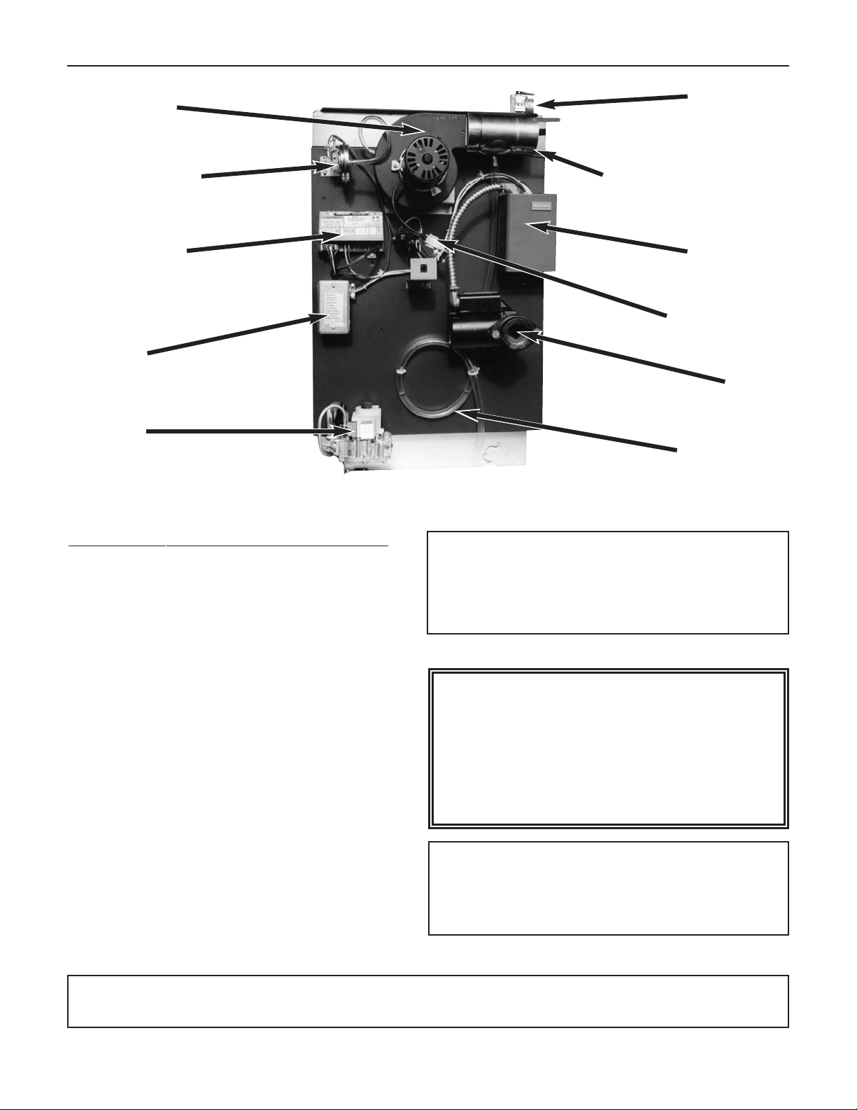
VI
CTORY
II V
HS MODELS
Blower assembly
Air flow proving switch
Ignition control
Junction box
Gas valve
Pressure relief valve
Adapter and condensation drain
Aquastat
Inducer relay
Circulator
Condensation trap
Figure 1. Location and identification of parts
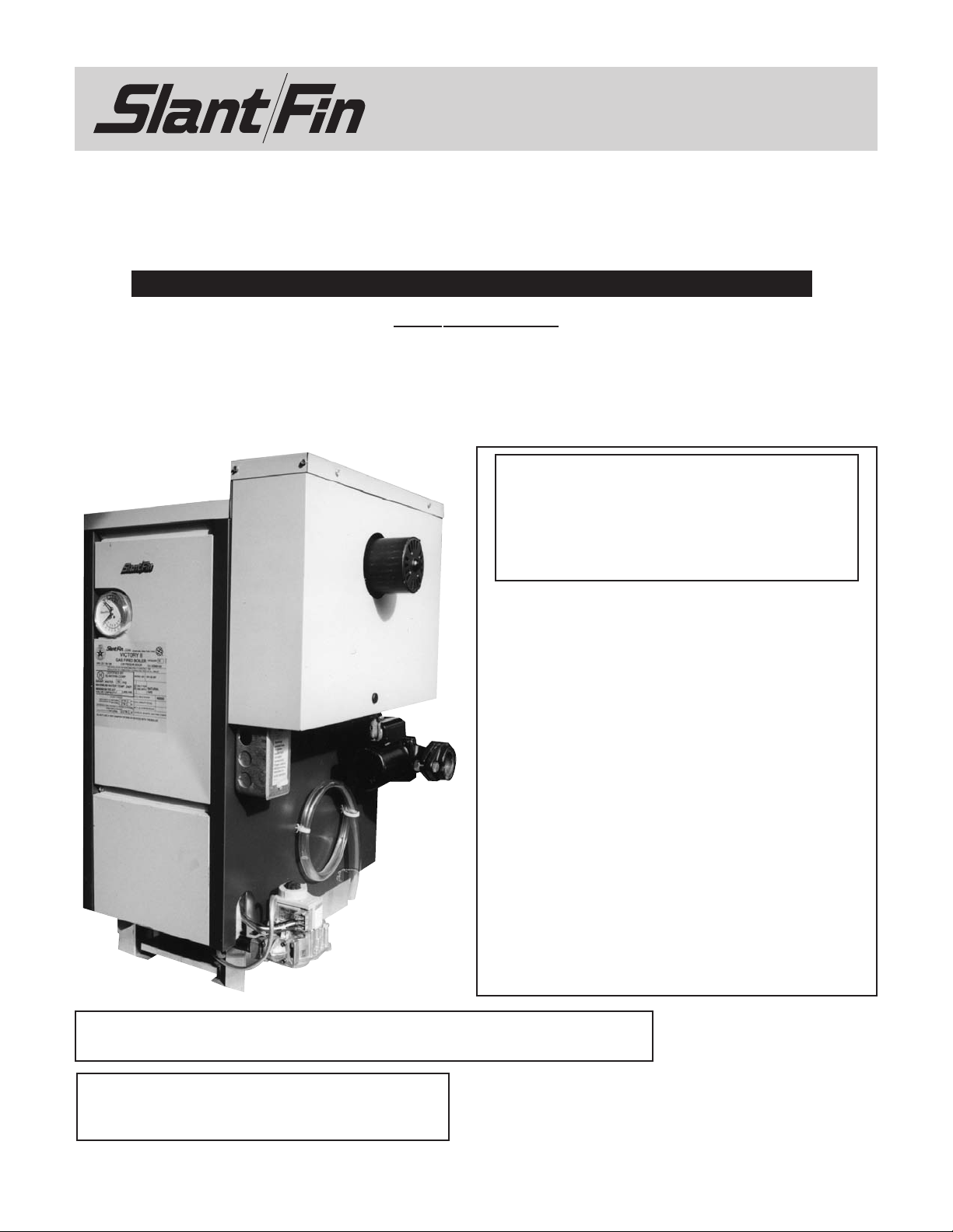
WELCOME TO OUR VALUED CUSTOMER
You are now the owner of a Slant/Fin Victory II
gas-fired boiler, another quality heating product
designed and manufactured by an industry leader,
to provide your family with many years of reliable
comfort and trouble-free performance.
The care and maintenance of your new boiler is
important to prevent a hazardous condition which
might result from lack of proper servicing.
Therefore, you should perform regular “owner”
inspections as described in this manual (and report
any concerns to a qualified service technician) as
well as have your boiler serviced by a qualified
service technician at least once a year, preferably
before the beginning of each heating season.
LIGHTING INSTRUCTIONS
Locate, read and then follow the procedures on the
lighting instructions label attached to the boiler. For
reference, we have reproduced those instructions
in this manual.
DO NOT use this boiler if any part has been
underwater. Immediately call a qualified service technician to inspect the boiler and to
replace any part of the control system and
any gas control which has been underwater.
WARNING
Should overheating occur or the gas
suppl
y fail to shut off, DO NOT turn off
or disconnect the electric supply to the
circulator pump. Instead, shut off the
gas supply at a location EXTERNAL to
the appliance.
WARNING
SLANT/FIN DOES NOT PERMIT THE USE OF VENT
DAMPERS ON VICTORY
OTHER DAMPERS OR DEVICES WITH SIMILAR
PURPOSE ARE NO
II SERIES BOILERS.
T PERMITTED.
Keep the boiler area clean and free of all materials that can burn.
NEVER close or reduce openings that supply air for the boiler fire and for ventilation.
2
Page 3
VI
CTORY
II V
HS MODELS
INSPECTION
Your boiler and heating system will last an indefinitely
long time at full efficiency, if it is inspected regularly
and is kept in good repair and adjustment. You, the
ser, should make regular inspections, and report any
u
roblems to your service agency. At regular intervals,
p
you should have that agency inspect the system, clean
the boiler and make repair adjustments as necessary.
What you and the service agency should do is listed
below. Contact your gas supplier for a list of qualified
service and repair agencies.
USER INSPECTION
The user should make the following inspections at
least once each month during the heating season and
once just before cold weather starts:
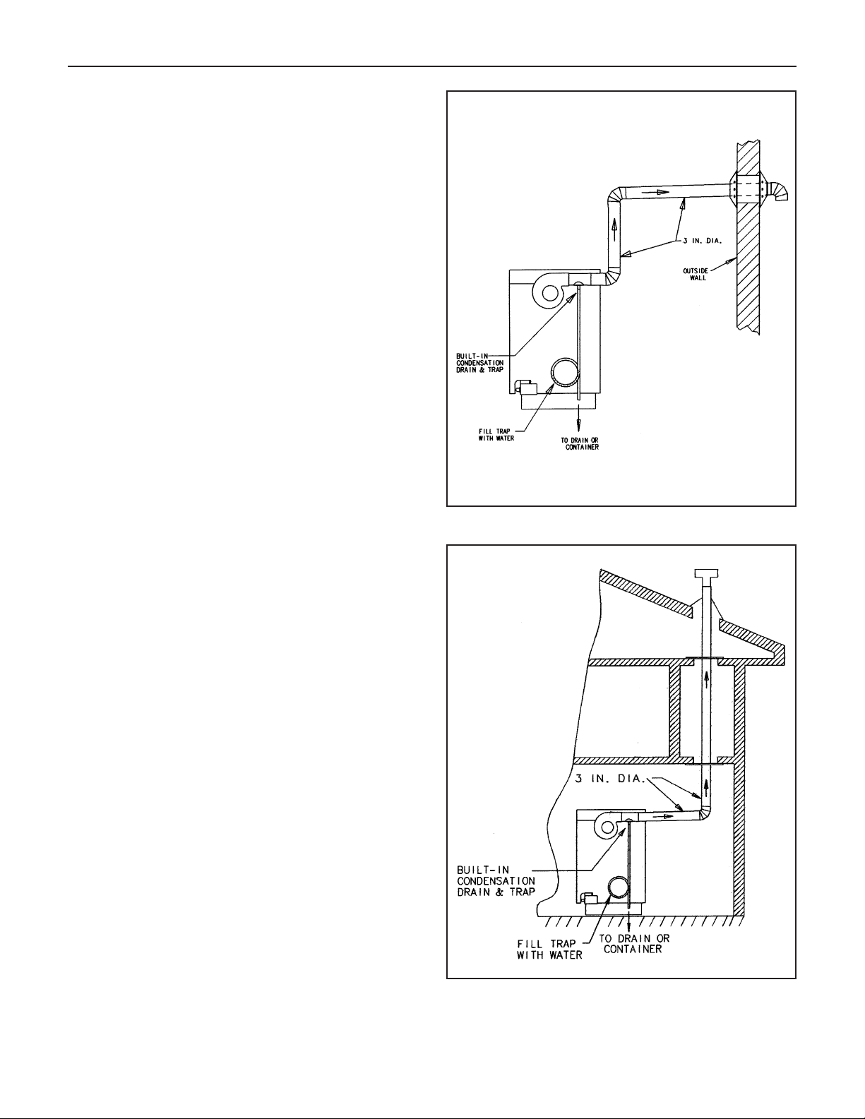
1. Venting system inspection
Horizontal or vertical venting inspection
A.
All Victory
II boilers may be vented horizontally
through an outside wall (see Figure 2), through
the roof (see Figure 3) or vertically utilizing an
existing chimney as a chase (see Figure 4). In
all cases a 3" diameter AL29-4C* stainless steel
venting material MUST be used.
Inspect the system regularly for condensation,
corrosion and/or physical damage. A qualified
professional should service the boiler annually
and include such an inspection at that time. The
homeowner should look over the system monthly for damage, water stains, any signs of rust,
other corrosion or separation of the flue (vent)
and fittings
.
Figure 2. Horizontal venting, side wall venting
Should an inspection turn up signs of condensation, corrosion or damage, the boiler should be
shut down immediately and the condition should
be corrected by a qualified professional.
If the boiler is vented horizontally through the
wall, the outside termination and screen should
be checked for any debris blocking the opening
and cleaned as required.
B. Chimney or Type “B” venting inspection
Only models VHS-90, VHS-120, VHS-150 and
VHS-180 may be vented directly into a chimney
with 5, 6, or 7 inch diameter standard metal smoke
pipe (galvanized). See Figure 5. Make sure pipe
joints are snug and are fastened with screws. The
chimney joint should be filled with cement to prevent leakage. There should be no visible signs of
rust or salts from water evaporation.
*: AL29-4C is a registered trademark of Allegheny Ludlum Corp.
Figure 3. Vertical venting through the roof
3
Page 4

Figure 4. Vertical venting through chimney
VI
CTORY
. Condensation drain trap inspection
2
heck condensation drain trap to be full of water. Check
C
II V
HS MODELS
for deterioration of the tubing. Check that trap is not
lugged. DO NOT operate the boiler without filling the
p
trap with water to prevent flue gas discharge into space.
The drain should extend to a floor drain or to a container which may require emptying periodically.
3. Piping inspection
Look at all water piping. There should be no leaks or
signs of leaks at any pipe joints or around the boiler.
4. System water pressure inspection
The temperature and pressure gauge indicates the
pressure in the boiler at each water temperature. For
most installations, it should indicate about 12 to 15 psi
pressure when temperature is about 70 to 100° F and
from 15 psi to 25 psi when temperature is up to 240° F.
FOR YOUR SYSTEM, there is one correct pressure for
each temperature. ASK YOUR INSTALLER OR SERVICEPERSON TO EXPLAIN AND SHOW YOU.
what normal pressures to look for.
es
from normal, your system is losing water. If pressure
If pressure decreas-
Learn
rises from normal, the relief valve will open to relieve
the pressure. Call your service organization if pressures
are higher or lower than normal, and if the relief valve
spills water. Repair or adjustment is needed.
5. Unusual noise
Stand near the boiler and look and listen. As the burners start and shut off, there should be no unusual noise.
No fire should be visible coming out from the front of
the boiler when the burners start or run.
6. Boiler room air supply inspection
Ample air is required for your boiler to burn fuel cleanly
and safely. Check to make sure all air vents are open
and free of obstruction. Air needs are greatest in cold
weather.
Figure 5. Chimney venting
4
WARNING: The flow of combustion and ventilating air
to the boiler should not be obstructed.
WARNING: If you find any problem during your
inspection, call for service immediately.
ANNUAL SERVICE TECHNICIAN INSPECTION
A trained and qualified service technician should perform these inspections before each heating season:
1. Safety check
Removing Control Box (cover). See Figure 6. To
remove control box:
a. Turn back screw 1/4 turn clockwise to open
position .
b. Remove two sheet metal screws in the top of control
box.
c. Remove control box.
T
o replace the box, reverse procedure. Be sure that
black screw is in the lower bracket receptacle and
loc
k position .
Page 5

VI
CTORY
Figure 6. Figure 7.
II V
HS MODELS
A. High limit control test
Set thermostat high enough for water temperature to reach high limit control setting of
Aquastat. When this temperature is reached, the
high limit switch should open and the main gas
valve should close automatically.
B. Gas control saf
With main burners firing, disconnect the ignition
cable from S8600 ignitor (see Figure 9). Gas
valve should shut off the main burners.
C. Air flow pressure switch test
With main burners firing, remove plastic hose
from Pressure Switch (see Figure 7). Gas v
should shut off the main burners.
WARNING: If any of the above controls fail to operate
properly, they must be replaced.
D. Checking for gas leaks
Using soap solution, check for gas leaks from
meter to burner, including gas piping, manifold
and pilot b
DO NOT use open flame.
2. Venting system inspection
See Page 3 for instruction.
ety shutdown test
alve
urner.
3. Condensation drain trap inspection
See page 4 for instruction.
4. Piping inspection
Check the following:
A. Water piping and accessories for leaks. Slightest
leaks should be corrected.
B. System to be full of water and pressure to
remain stable at correct setting on gauge.
C. Air-control system. Noise and air binding in radi-
ation should not occur.
D. Low water cutoff for operation (see instructions
furnished with unit).
E. Check water pressure and add w
system when needed. If much water is added,
venting may be necessary. Regular loss of water
from boiler system may indicate either a system
leak, or a faulty air control system, or a faulty
automatic fill valve.
5. Boiler room air supply inspection
Check air vents for continued positive supply of air
as required. Air needs are greatest in cold weather.
Air vents must be open and free of obstruction.
WARNING: The flow of combustion and ventilating air
to the boiler should not be obstructed.
ater slowly to
ANNUAL SER
INSPECTION AND CLEANING
A.
Flue passage cleaning
See Figure 8. It is suggested that paper be placed on
burners to collect any foreign material in cleaning flues.
1. Remove control box (see instruction under
“Safety Check”).
VICE TECHNICIAN
5
Page 6

VI
CTORY
II V
HS MODELS
. Remove jacket top.
2
. Remove inducer assembly.
3
4. Remove flue collector.
5. Use wire brush to clean flue passages.
. Replace flue collector and re-seal with
6
furnace cement.
7. Replace inducer assembly, jacket top and
control top.
8. Remove and dispose of paper and accumulated
material.
C. Adjust main burners and pilot flames. See
“Installation and Operating Instructions”, for instructions.
D. Check input gas rate to the burners. See
Installation and Operating Instructions”, for instruc-
“
ions.
t
E. To prolong the life of inducer motor, lubricate with
6 drops of Anderol 465 annually.
FLAME ROLL-OUT SAFETY SHUT-OFF SWITCH
All Victory II boilers are equipped with a single use
flame roll-out safety shut-off switch. It will shut off main
gas burners in the event the flow of combustion products through the boiler flue passages are reduced. If this
safety switch has actuated to shut off the main burners,
DO NOT attempt to place the boiler in operation, but
contact a qualified service agency.
SAFETY AND OPERATING INSTRUCTIONS
Follow the lighting instructions in this manual. These
instructions are also attached to the boiler.
SAFETY INFORMATION
For Your Safety Read Before Operating
Figure 8.
B. Cleaning of burners
If burners’
indicates plugged burner parts, remove and clean
burners.
1. Remove pilot gas line at gas valve.
2.
Disconnect pilot burner assembly from pilot
bracket.
3. Lift burner and remove burner from orifice.
4. Clean burners. To clean burners, run a clean flue
brush up the tube until all foreign matter is
removed.
5. Replace burners, pilot assembly, ignitor and sen-
sor wires.
6. Adjust burners and pilot flame.
surfaces are not clean, or uneven flame
WARNING: If you do not follow these instructions
exactly, a fire or explosion may result causing property damage, personal injury or loss of life.
A. This appliance is equipped with an ignition device
which automatically lights the pilot. DO NOT try to
light the pilot by hand.
B. BEFORE OPERATING smell all around the appli-
ance area for gas. Be sure to smell next to the floor
because some gas is heavier than air and will settle
on the floor.
WHAT TO DO IF YOU SMELL GAS:
• DO NOT try to light any appliance.
• DO NOT touch any electric switch: DO NOT use
any phone in your building.
• Immediately call your gas supplier from a neighbor’s phone. Follow the gas supplier’s instructions.
• If you cannot reach your gas supplier, call the fire
department.
6
Page 7

VI
CTORY
II V
HS MODELS
C. DO NOT use this appliance if any part has been
underwater. Immediately call a qualified service technician to inspect the appliance and to replace any
part of the control system and any gas control which
as been underwater.
h
Figure 9.
OPERATING INSTRUCTIONS
1. STOP! Read the safety information on page 6.
2. Set the thermostat to lowest setting.
3. Turn off all electric power to the appliance.
4. This appliance is equipped with an ignition device which
automatically lights the pilot. DO NOT try to light the pilot
by hand.
5. Turn gas control knob clockwise to “OFF”.
DO NOT force.
6. Wait five (5) minutes (longer for propane) to clear out any
gas. Then smell for gas, including near the floor. If you
smell gas,
page 6. If you don’t smell gas, go to next step.
7. Turn gas control knob counterclockwise to “ON”.
8. Turn on all electric power to the appliance.
9. Set thermostat to desired setting.
10. If appliance will not operate, follow the instructions
“To Turn Off Gas To Appliance” and call your service or
gas supplier.
STOP! Follow “B” in the safety information on
Figure 10.
To turn off gas to appliance
1. Set thermostat to lowest setting.
2. Turn off all electric power to the appliance if service is to be
performed.
3. Turn gas control knob clockwise to “OFF”.
DO NOT force.
Your gas boiler must be installed and serviced by a
qualified service agency or gas supplier. The lack of
proper service can result in a dangerous condition.
7
Page 8

SLANT/FIN CORPORATION, Greenvale, N.Y. 11548 • Phone: (516) 484-2600
FAX: (516) 484-5921 • Canada: Slant/Fin LTD/LTEE, Mississauga, Ontario
www
.slantfin.com
 Loading...