

Page 1
HOT WATER/GAS
MODULAR BOILERS
®
APPLICATION GUIDE
Guidelines for the design, purchase and installation of Slant/Fin Jaguar Caravan gas-fired, hot water modular boiler systems.
CONTENTS
Introduction . . . . . . . . . . . . . . . . . . . . . . . . . . . . . . .2
Recommended Piping . . . . . . . . . . . . . . . . . . . . . .2
Optional factory supply and return headers . . . . . .7
SC- control bill of materials . . . . . . . . . . . . . . . . . .9
Gas piping . . . . . . . . . . . . . . . . . . . . . . . . . . . . . . .9
Controls . . . . . . . . . . . . . . . . . . . . . . . . . . . . . . . .11
Field wiring at modules . . . . . . . . . . . . . . . . . . . . .12
SC-3 system wiring . . . . . . . . . . . . . . . . . . . . . . . .12
SC-9 space heating wiring . . . . . . . . . . . . . . . . . .14
SC-9 space and domestic hot water wiring . . . . .16
CODES AND STANDARDS
All Caravan installations must comply to local codes or, in the
absence of local codes, to the National Fuel Gas Code, ANSI,
Z223.1-latest edition.
In addition where required by the authority having jurisdiction, the
installation must conform to American Society of Mechanical
Engineers Safety Codes for controls and safety devices for
automatically fired boilers, No. CSD-1. The installation must also
conform to the additional requirements of Slant/Fin Instruction Book
publication no. J-40 latest edition.
All electrical wiring is to be done in accordance with the National
Electrical Code ANSI/NFPA No. 70-latest edition and all local electrical codes. The unit must be electrically grounded if an external
wer source is used.
po
In Canada, the installation must be in accordance with standards
CGA B149.1 and B149.2, installation codes for gas burning
appliances and equipment and/or local codes. All electrical
connections are to be made in accordance with Standard C.S.A.
C22.1 Canadian Electrical Code Part 1 and/or local codes.
INTRODUCTION OF FRESH WATER
Introduction of excessive amounts of fresh water into a system can
cause scaling and leave deposits in the boiler and the surrounding
pipes. This will lead to inefficient boiler operation and breakdown.
Fresh water will enter the system as a result of hidden leaks such
as may occur in underground piping. Relief valves should be piped
to a location that shows visible signs of relief.
Process applications that use fresh water
exchangers. Any process application that results in introduction of
ater into a boiler can cause scaling with deposits for
fresh w
the boiler and surrounding piping. This will damage the boiler.
Introduction of fresh water from leaks will cause similar damage.
In some areas it ma
control the corrosive makeup of the feed water. Check with the local
authority, to determine if the feed water will need a conditioning
treatment before being supplied to the boiler.
y be necessary to use a f
, require the use of heat
ming in
eed water treatment to
Printed in the U.S.A. 1008 Publication No. CJ-10-HWG
www.slantfin.com
Page 2

Jaguar Caravan Modular Boilers2
INTRODUCTION
This application manual is intended to provide the piping and control
method for applying multiple Jaguar J-390 boilers to a space heat-
ng and domestic hot water heating system. Use this manual, in
i
conjunction with the Jaguar J-390 Installation and Operating
Instructions, publication J-40.
The following sections of the Installation and Operating Instructions
must be adhered to:
1. Boiler location and foundation
2. Clearances to combustibles
3. Contamination prevention
. Air supply and ventilation
4
5. Venting application and materials*
6. Water treatment
7. Condensate disposal
8. Operating instructions
9. Care and Maintenance
*Common venting of these appliances is not permitted. Vent pipes in
a non-direct venting system can be clustered together, at their termination point. Direct vent terminals cannot be clustered together or
stacked vertically. Direct vent terminals can be mounted side by side
horizontally, provided there is a 12" minimum distance between
them.
RECOMMENDED PIPING AND WATER FLOW
Good system design addresses flow rates through boilers. It is
possible to have too little flow and too much flow. Most boiler system designs are based on a 20˚F to 30˚F temperature rise in the
boiler when it is firing at full input.
When the flow rate is too high through a module the water flow
tends to short circuit from the return tapping to the supply tapping
of a module. When flow rate is too high the boiler efficiency may
drop and there is excess electrical consumption by the circulator.
Primary/secondary piping is recommended for multiple Jaguar
oilers. This method ensures that each boiler will receive the
b
same inlet water temperature, and only the boilers that are firing
will have water flowing through them. Each boiler must have a
dedicated circulator piped on it’s supply. See figures 1a through 4
or the location of components and piping layout.
f
If a single low water cutoff is installed in the common header
water piping to protect all of the boilers, no isolation valves are
permitted on the individual boiler piping between the low water
cutoff and each boiler. See figures 1a and 2a.
If isolation valves are installed in the individual boiuler piping to
the common headers, a dedicated low water cutoff must be
installed on each boiler’s piping, as close to the boiler as possible
and beneath the isolation valves. See figures 1b and 2b.
SPACE HEATING
The primary loop must have its own system pump, and closely
spaced tees for the secondary loop interconnection. By keeping
the pressure drop very low, water that is flowing in the primary
loop will not flow into the secondary circuit until each boiler’s circulator turns on.
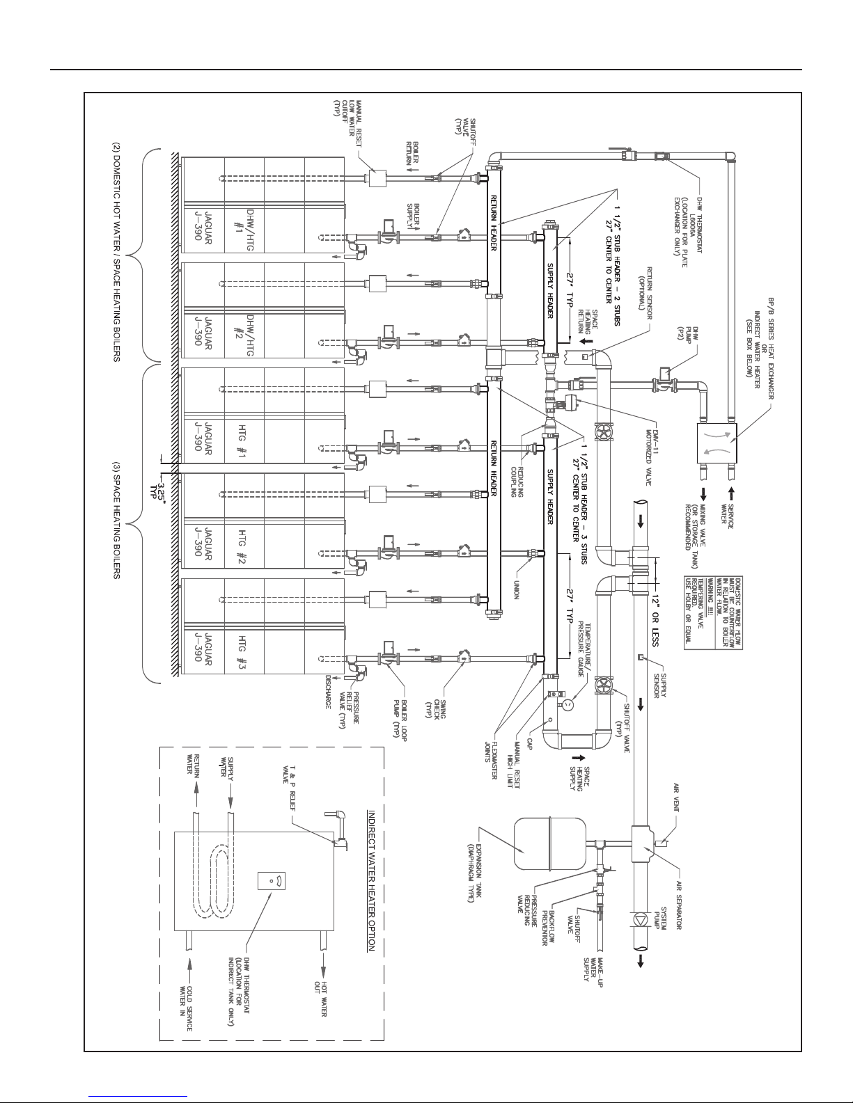
DOMESTIC HOT WATER HEATING
A motorized valve can be installed within the supply water heater
to divert the water flow of one or more boilers to a heat exchanger during a domestic water need. See figures 2a and 2b. This can
provide instantaneous delivery or storage of the domestic hot
water. See figures 2a through 4 for method.
Page 3
Jaguar Caravan Modular Boilers 3
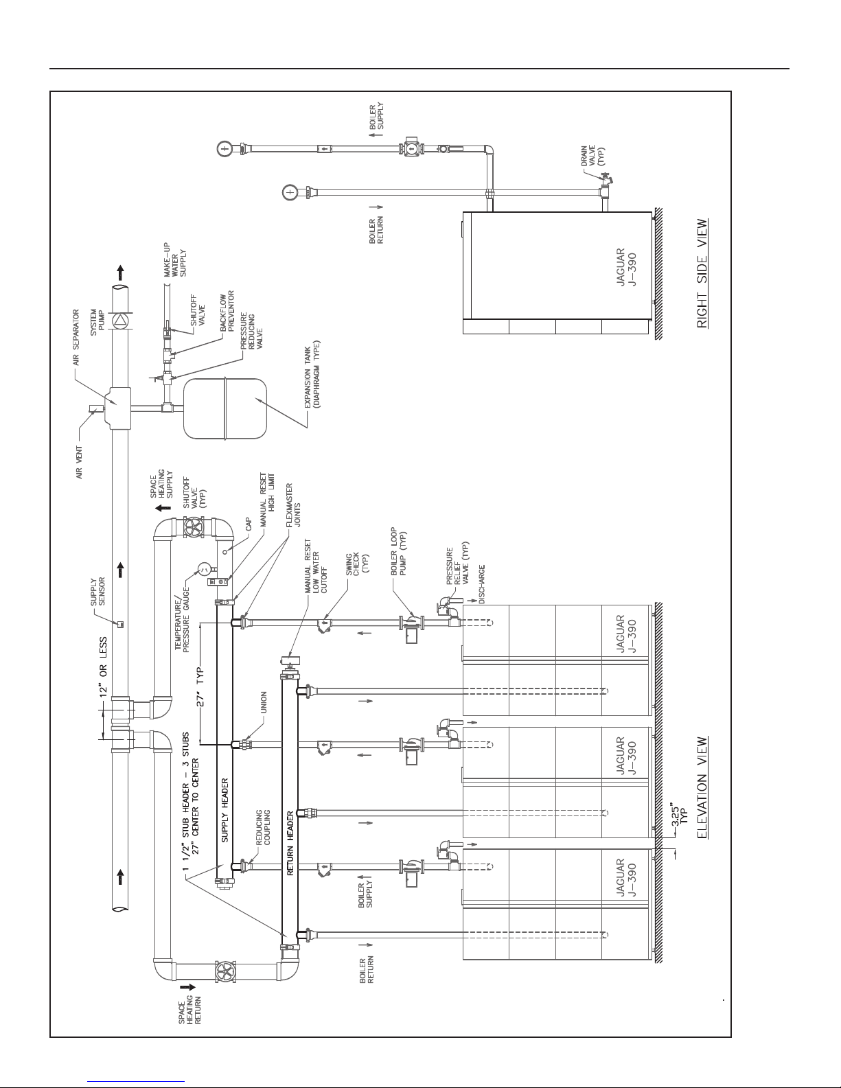
Figure 1a. Jaguar multiple boiler space heating primary- secondary pumping system with low water cutoff in common header.
Page 4
Jaguar Caravan Modular Boilers4
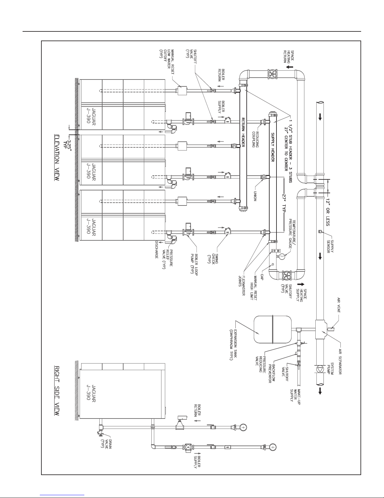
Figure 1b. Jaguar multiple boiler space heating – Primary-secondary pumping system with low water cutoffs on each individual boiler.
Page 5
Jaguar Caravan Modular Boilers 5
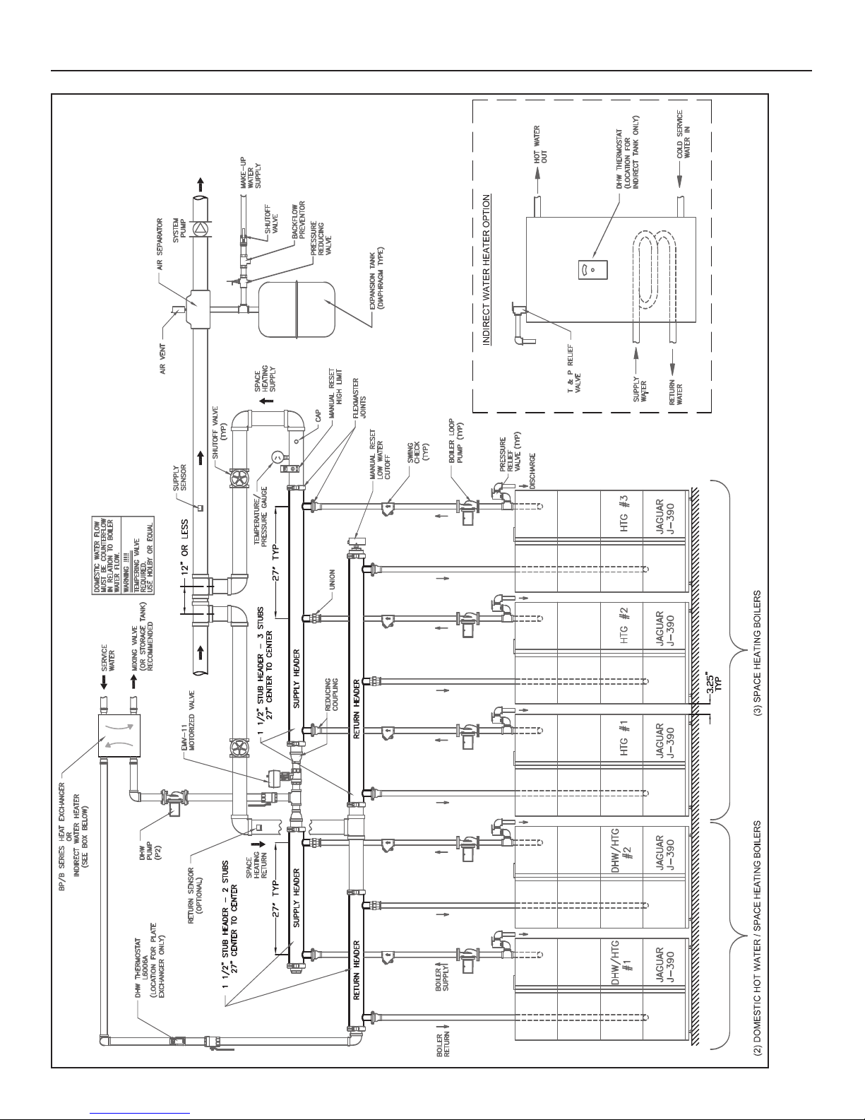
Figure 2a. Jaguar multiple boiler space heating and domestic hot water primary-secondary pumping system with low water cutoff in common header.
Page 6
Jaguar Caravan Modular Boilers6
Figure 2b. Jaguar multiple boiler space heating and domestic hot water. Primary-secondary pumping with low water cutoffs on each individual boiler.
Page 7

Jaguar Caravan Modular Boilers 7
Figure 3. Instantaneous tankless coil—
two temperature with recirculation
Figure 4. Storage tank from tankless coil with recirculation
OPTIONAL EQUIPMENT (See figure 5) Header and Control Systems Available:
Header System Parts Quantity needed for number of boilers installed
Item Part No. 2 3 4 5 6 7 8 9
1-1/2" Stub Header - 2 stub - 27" C-C (pkgd. separately) 43-0920 2 – 4 2 – 4 2 –
1-1/2" Stub Header - 3 stub - 27" C-C (pkgd. separately) 43-0921 – 2 – 2 4 2 4 6
Flex Joint 1-1/2" pipe 43-2023 2 4 4 6 8 8 10 12
Flex Joint - 3" pipe 43-1755 4 4 8 8 8 12 12 12
Cast End Cap - No tap 43-1753 2 2 2 2 2 2 2 2
* Header Notes:
Gaskets are EPDM with +275˚F maximum temperature rating.
Maximum pressure rating exceeds maximum boiler pressure rating
of 30 psi.
Flex joint is designed to seal pipe connections. Normal hangers,
guides, anchors and other external piping restraints must be used to
restrain piping system from movement.
• Some governing agencies do not allow compression type
couplings. Consult your local code requirements.
• Building piping must be rigidly secured so it cannot move where
connected to headers.
Figure 5.
Header assemb
l
ultiple Jaguar boilers
or m
y f
Page 8

Jaguar Caravan Modular Boilers8
Caravan Flex Joint Assembly Instructions
1. Slip the metal retainer on the system piping with the larger
diameter side facing the end of the pipe to be joined. The
" flex joint has a single piece serrated metal retaining
3
ring. This retaining ring should be seated in the recess in
the inner diameter of the gasket with its mounting tabs
over-lapping slightly where the ring splits. The 1-1/2" flex
joint has a 2 piece serrated retaining ring that must be
installed in the inner recess of the gasket with its ends
butting.
Work the gasket with the serrated metal retaining ring onto the pipe. When installing the gasket be sure the retaining rings
seat properly around the pipe. On the 1-1/2" flex joint install the bottom half of the gasket first leaving the other half of the
retaining ring free at the top. Then stretch the top of the gasket with the ring over the top of the pipe.
gaskets if a lubricant is needed, use a soap and water solution only. DO NOT use any oil based lubricants.
2. The gasket must be fully seated in the metal retainer (press together with pliers if necessary). BE SURE THE GASKET IS
SEATED ON AN UNTHREADED SECTION OF PIPE AT LEAST 1" FROM THE END. Slip the flared end of the Slant/Fin
header tube over the pipe and seat against the gasket. Follow illustration a or b for cast end cap or piping.
a) b)
When installing the
3. Open hinged metal clamp and slip over joint. Be sure that the flared end of the steel tubing, the retainer ring and the
gasket are enclosed within the clamp.
4.
Page 9

Jaguar Caravan Modular Boilers 9
BILL OF MATERIALS FOR SC SERIES CONTROLLERS
Material List f
• SC-3 modular boiler control (part#435-084)
1 Outdoor sensor (part#339-070)
•
• 1 Universal sensor to be used as supply water sensor
(part#339-071)
• 1 plastic tie strap
Material List for SC-9
1 SC-9 modular boiler control (part#435-085)
•
• 1 Outdoor sensor (part#339-070)
2 Universal sensors (part# 339-071)
•
– 1 to be used as supply water sensor
– 1 can be used as return water sensor
• 2 plastic tie straps
GAS PIPING
This section contains sizing and construction recommendations
for fuel supply piping to Caravan gas-fired modular boiler systems. Gas-fired equipment must conform not only to codes of
local regulatory agencies, but also to additional specifications that
may be imposed by the utility or gas supplier. Therefore, the following information should be considered only as a guideline.
Figure 6 illustrates a typical gas supply line installation. It consists
of a main between the utility’s meter box and the boiler system, a
main shut-off valve sediment trap, gas header pipe and drip legs
on individual boilers.
Individual gas lines to individual boiler modules should be equal
to or greater than the boilers supplied gas connection diameter.
Size of gas main and header pipes depends on volume of gas
required and acceptable pressure drop between meter and modules gas regulator valves. Minimum pressure required at each
valve is 3 inches of water column for natural gas measured while
all boilers and other gas-fired equipment on the same meter are
firing. Final pressure of gas header must vary no more than +0.3
in. of water column.
or SC-3
Other Options include:
Immersion well for supply water sensor: to be installed in
•
control header supplied with Caravan
• High limit (manual reset) and immersion well: to be installed in
control header supplied with Caravan
• Low water cut-off (manual reset): to be installed in modular
boiler headers above modules heat exchanger
• Domestic hot water control packages: components include
EMV valve; setpoint aquastat L6006A with immersion well.
This is to be used with external heat exchanger such as
aravan BP series brazed plate heat exchangers.
C
Circulators, switches, wiring and other relays are provided by
contractors.
GAS MAIN SIZING
To determine the correct pipe diameter for the gas main serving a
specific Caravan system, proceed as follows:
a. Follow the building plans, find total length of straight pipe
between supply from gas meter and boiler gas header.
b. Using data in Table 2, calculate equivalent linear length of
screw pipe fittings used in fabrications of main. Add this to
figure from step (a) to obtain equiv
c. Find Caravan gas consumption in cubic feet per hour from
Table 1 in hot water systems.
d. Multiply the system total hourly gas consumption by flow
correction value from local utility. If not available, use
1000 btu/ft.
e. Locate system’s total equivalent pipe length in right column
of Table 3.
f. Move vertically to the system’s corrected flow rate calculated
in step (c). If this value falls between two of those listed,
selected larger value.
g. From this point move horizontally to the left column and read
suggested pipe diameter for gas main.
alent total length.
Number
of boilers
2 780
3 1170
Cubic feet
per hour
Pipe
SIze
Inches
1/2
3/4
4 1560
5 1950
1-1/4
1-1/2
6 2340
7 2730
Table 2. Equivalent linear length in feet of standard iron pipe fittings for natural gas
8 3120
9 3510
Table 1. Gas consumption rate.
1
2
3
Standard
0.84
1.17
1.57
2.19
2.63
3.55
5.72
Elbow Valve
Medium
Sweep
0.52
0.73
0.98
1.37
1.64
2.23
3.59
Long
Sweep
0.41
0.57
0.77
1.07
1.29
1.74
2.81
Gate Globe Angle
0.031
0.044
0.057
0.082
0.098
1.320
2.130
2.50
3.50
4.68
6.54
7.84
10.60
17.08
1.12
1.84
2.11
2.94
3.52
4.77
7.69
Return
Bend
1.25
1.75
2.34
3.27
3.92
5.30
8.84
Side
Outlet
Tee
1.66
2.33
3.11
4.35
5.21
7.05
11.40
Page 10

Jaguar Caravan Modular Boilers10
Nominal
Iron Pipe
Size Inches
1/2
3/4
1
1-1/4
1-1/2
2
1-1/2
3
4
Table 3. Gas main sizing guide
Internal
Diameter
Inches
.622
.844
1.049
1.380
1.610
2.067
2.469
3.068
4.026
Equivalent Length of Pipe, Feet
10 20 30 40 50 60 70 80 90 100 125 150 175 200
132
278
520
1,050
1,600
3,050
4,800
8,500
17,500
92
190
350
730
1,100
2,100
3,300
5,900
12,000
73
152
285
590
890
1,650
2,700
4,700
9,700
63
130
245
500
760
1,450
2,300
4,100
8,300
56
115
215
440
670
1,270
2,000
3,600
7,400
50
105
195
400
610
1,150
1,850
3,250
6,800
46
96
180
370
560
1,050
1,700
3,000
6,200
43
90
170
350
530
990
1,600
2,800
5,800
40
84
160
320
490
930
1,500
2,600
5,400
38
79
150
305
460
870
1,400
2,500
5,100
34
72
130
275
410
780
1,250
2,200
4,500
31
64
120
250
380
710
1,130
2,000
4,100
28
59
110
225
350
650
1,050
1,850
3,800
26
55
100
210
320
610
980
1,700
3,500
Maximum capacity of pipe in cubic feet gas per hour for gas pressure of 0.5 psig or less and a pressure drop
of 0.3 inch water column (based on a 0.60 specific gravity gas).
ypical gas supply installation for Jaguar boiler.
Figure 6.
T
Page 11

Jaguar Caravan Modular Boilers 11
The Boiler Staging Concept
The heart of the Caravan boiler plant is temperature-actuated control system that automatically stages only those boiler modules
needed to meet the heating demand in a given period, thereby conserving fuel.
In a staging control system, each stage ordinarily activates one boiler module. With appropriate wiring, multiple modules can be
rouped within a stage.
g
During a fluctuation in heating requirements, a large central boiler
ycles on and off to match heat output to building demand. A
c
staged modular boiler system, on the other hand, will energize only
as many modules as the system load requires. Only one stage
cycles at a time. The other stages remain off or operate continuously, thereby performing at peak efficiency. For example, in a 10 module boiler system, with the heating load at 61% of capacity, six of the
modules operate continuously at peak efficiency. Fractional heating
requirements are supplied by the seventh “cycling” modules, while
the remaining three modules are “off”. This is in contrast to a single
large centr
efficiency.
Over-sizing is a major factor in poor system efficiency. Most of the
time a single central boiler is oversized. Historical data shows that
many single central boilers are considerably oversized even at the
outdoor temperature for which they were designed. Modular boiler
systems are not oversized by more than a portion of one module,
regardless of the load.
The Caravan control system automatically compensates for seasonal temperature changes, It energizes more or fewer modules
depending on changes of outside temperature, system water temperature, or both. Modules save energy by operating in long cycles
at full-rated output and maximum efficiency.
al boiler that simply cycles on and off, resulting in lower
Control System Selection
Slant/Fin offers two controls to step fire a hot water Caravan system.
The SC-3 and Sc-9 controls fulfill a wide range of applications. They
control the boiler system and are not intended to be the sole building temperature control. They do not replace zoning the system or
the thermostats that control these zones.
SC-3 Controls
The SC-3 control allows up to 3 stages in a Car
Gener
ally each stage controls 1 module. However, it is possible to
have more than 1 module activated with each stage.
See figures 7a and 7b.
Standar
de-activation based on outdoor temperature; minimum target supply
water temperature; adjustable design target supply water temperature; adjustable delay between stages adjustable outdoor temperature and indoor design temperatures.
The view menu on the control includes error messages, actual outdoor air temperature, actual supply water temperature target supply
water temperature and running time for each stage.
The SC-3 contr
1. Outdoor reset: The supply water temperature is
2.
d programmable features include:
ol can be pr
automatically adjusted up or down based on outdoor
ature. the control automatically controls the
temper
number of modules required to maintain required supply
water temperature.
Setpoint temperature:
maintain a set supply w
automatically controls the number of modules activated to
maintain the setpoint temper
ogrammed as follows:
The control can be prog
ater temper
ature. The control
.
ature
avan system.
system activ
ammed to
r
ation or
SC-9 Controls
The SC-9 control allows up to 9 stages of operation for space heating,
domestic water or combination, in a Caravan system. Generally each
stage controls 1 module. However, it is possible to have more than one
module activated with each stage, See figures 8a through 10b.
Standard programmable features include: system activation or
de-activation based on outdoor temperature; minimum target supply
ater temperature; adjustable design target supply water tempera-
w
ture; adjustable delay between stages; adjustable outdoor and
indoor design temperatures; delay to allow combustion air damper
to open; ability to provide equal run time rotation of boiler modules;
fixed lead of a module when Caravan system activates; first on/last
off or first on/first off for modules; control of primary circulator and
periodic exercising of primary circulator when system is inactive.
The view menu on the control includes error messages, actual outdoor air temperature, actual supply water temperature, target water
temperature, running time for each stage and the difference
between supply water and return water temperatures.
The Sc-9 control can be programmed as follows:
1. Outdoor reset: The supply water temperature is
automatically increased as outdoor temperature decreases
and decreased as outdoor temperature increases. The
control activates only the number of stages required to
maintain the required supply water temperature.
2. Setpoint temperature: The control maintains a set supply
water temperature. The control activates only the number of
stages required to maintain the setpoint temperature.
Setpoint temperature may be used for Caravan system
that is dedicated for use as volume water heating.
3. Domestic hot water: The domestic hot water controls
override the SC-9 control for only those modules used to
heat the domestic hot water.The modules for domestic hot
water are isolated from space heating system until demand
for domestic hot water is satisfied. The modules not used for
domestic hot water heating remain under control of
SC-9 control.
Slant/Fin offers domestic hot water control packages and
external tankless heaters as options for use with the SC-9
control.
Controls Interaction
Each multiple boiler’s control must be programmed to properly
interact with the Caravan control, and all the parameters must be
consistent. There are 4 methods that can be utilized, based on
the desired function:
A. Caravan control using a thermostat/boiler control
programmed for fixed water setpoint temperature. Best
method for systems where domestic hot water is to be
generated. Each boiler’s modulation will be minimal.
B. Caravan control using a thermostat/boiler control utilizes an
outdoor sensor, provides more frequent boiler modulation.
Not recommended for domestic hot water generation.
C. Car
D.Car
avan control using an outdoor sensor/boiler control
programmed for fixed water setpoint temperature. Provides
some degree of boiler modulation, where domestic hot water
generation is needed.
avan control using an outdoor sensor/boiler control also
utilizes an outdoor sensor. Best methods for increasing boiler
modulation, providing the boiler’s control parameters are in
sync with Caravan. Not recommended for domestic hot water
generation.
Page 12

Jaguar Caravan Modular Boilers12
Figure 7a. SC-3 space heating wiring diagram for Jaguar boilers with low water cutoffs in common header.
Page 13

Jaguar Caravan Modular Boilers 13
s with low water cutoffs on each individual boiler.
guar boiler
or Ja
gram f
SC-3 space heating wiring dia
Figure 7b.
Page 14

Jaguar Caravan Modular Boilers14
Figure 8a. SC-9 space heating wiring diagram for Jaguar boilers with low water cutoff in common header.
Page 15

Jaguar Caravan Modular Boilers 15
Figure 8b. SC-9 space heating wiring diagram for Jaguar boilers with low water cutoffs on each individual boiler.
Page 16

Jaguar Caravan Modular Boilers16
Figure 9a. SC-9 space heating and domestic hot water wiring diagram for Jaguar boilers with low water cutoff in common header - using plate heat exchanger
Page 17

Jaguar Caravan Modular Boilers 17
Figure 9b. SC-9 space heating and domestic hot water wiring diagram for Jaguar boilers with low water cutoffs on each individual boiler – using plate heat exchanger.
Page 18

Jaguar Caravan Modular Boilers18
Figure 10a. SC-9 space heating and domestic hot water wiring diagram for Jaguar boilers with low water cutoff in common header - using indirect water heater
Page 19

Jaguar Caravan Modular Boilers 19
Figure 10b. SC-9 space heating and domestic hot water wiring diagram for Jaguar boilers with low water cutoffs on each individual boiler – using indirect water heater.
Page 20

Printed in the U.S.A. 1008. Publication No. CJ-10-HWG
2008.
.
Slant/Fin Cor
©
p
SLANT/FIN CORPORATION, Greenvale, N.Y. 11548 • Phone: (516) 484-2600
AX: (516) 484-5921
F
• Canada:
Slant/Fin
TD/LTEE
L
, Mississauga, Ontar
.slantfin.com
www
io
 Loading...