

Page 1
®
HOT WATER SUPPLY AND RETURN HEADERS
PARTS LIST AND ASSEMBLY INSTRUCTIONS
G-Series: Gas-Fired Modular Boilers
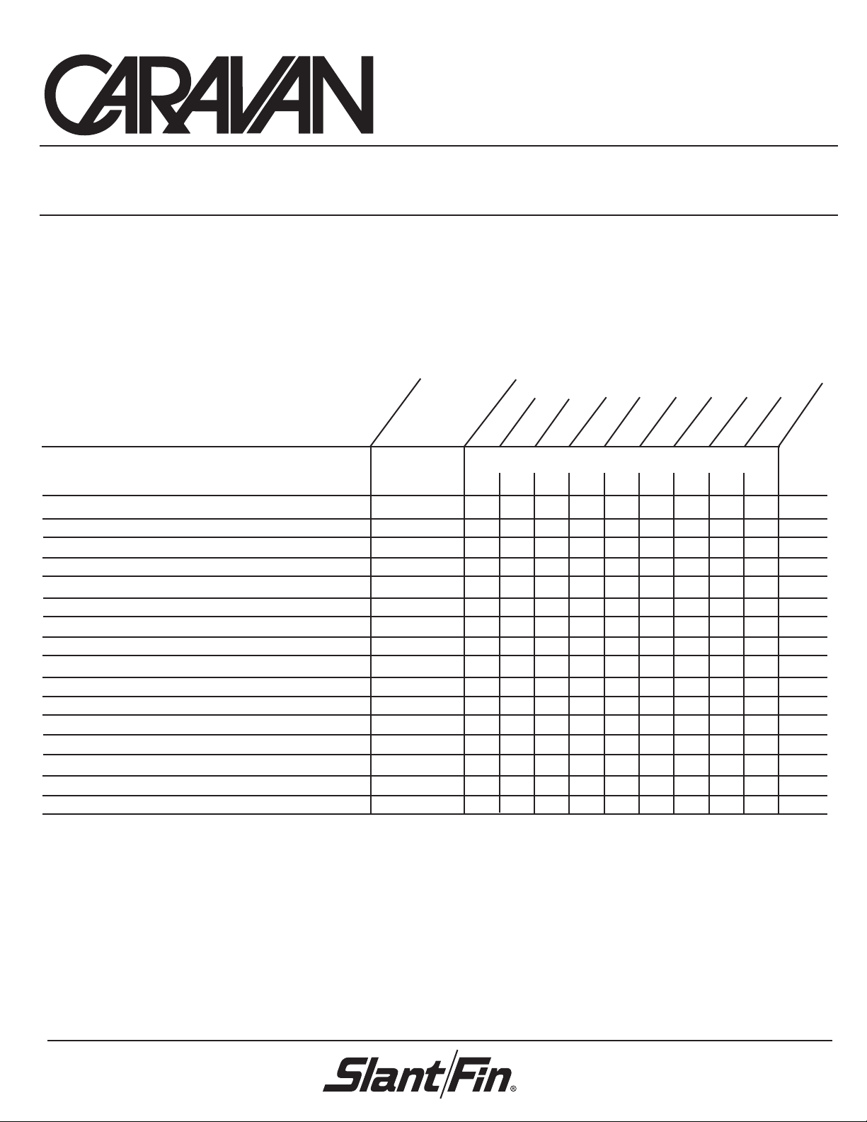
Header Parts List
41-2042
41-2043
Item Part No. 234 56 78910
1-1/2" Stub Header - 2 stub - 32" C-C (pkgd. separately) 41-2021 2–4 2– 42–4
1-1/2" Stub Header - 3 stub - 32" C-C (pkgd. separately) 41-2022 –2–24 2464
Flex Joint - 1-1/2" pipe 41-2023 244 68 810 12 12
Flex Joint - 3" pipe 41-1755 448 8812 12 12 16
Cast End Cap - 3/4" NPT 41-1780 111 11 1111
Cast End Cap - No tap 41-1753 111 11 1111
Nipple - 1-1/2" x 8" 41-2024 346 7810 11 12 14
Nipple - 1-1/2" x 18" 41-2025 112 22 3334
Nipple - 1-1/2" x 4" 43-0904 234 56 78910
Square Nipple - 1-1/2" x 10" T.O.E. 41-2027 122 34 4566
Square Nipple - 1-1/2" x 20" T.O.E. 41-2028 12234 4566
Union - 1-1/2" 90-2428071 224 44 6666
Tee - 1-1/2" 43-0917 46810 12 14 16 18 20
Bushing - 1-1/2" x 1/4" 41-2036 23456 78910
Bushing - 1-1/2" x 3/4" 90-2179321 234 56 78910
Installation Instructions 41-1775 111 11 1111
Header Package Order Code
Number of Modules
Part No. 41-1775
Publication CH-40G
Printed in U.S.A. 807
Page 2
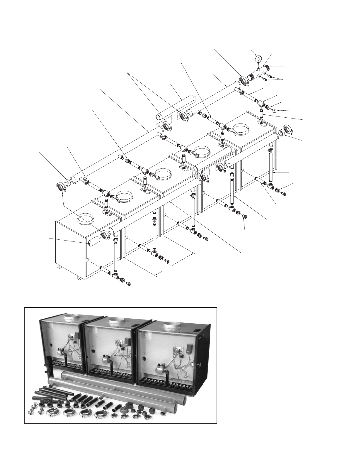
FACTORY SUPPLY AND RETURN HEADER ASSEMBLY — GAS
20”
CAST END CAP
SUPPLY HEADER
WITH THREE 1-1/2” STUBS
1-1/2” UNION
1-1/2” FLEX JOINT
(SEE DETAI L “A”)
3” FLEX JOINTS
(SEE DETAI L “A”)
1-1/2” NIPPLE 8”
3” PIPE x 28”
TYPICAL
(BY OTHERS)
3” FLEX JOINT
(SEE DETAI L “A)
SUPPLY HEADER
WITH TWO
1-1/2” STUBS
1/2” TRIDIC ATOR
GAUGE
CONTROL HEADER
3” x 1/2” x 1/2” x 1/2”
3” BUILDING PIPING
CONNECTION
1/2” WELLS
1-1/2” SQUARE NIPPLE x 10”
1-1/2” T EE
1-1/2” x 1/4” BUSHING
TRIDICAT OR
1-1/2” NIPPLE x 4”
CAST END CAP
WITH 3/4” TAPPING
RETURN HEADER
WITH TWO 1-1/2” S TUBS
1-1/2” SQUARE NIPPLE x
1-1/2” x 3/4” BUSHING
1-1/2” NIPPLE x 8”
* 3” BUILDING PIPING
(BY OTHERS)
32” T Y P.
1-1/2” NIPPLE x 18”
3/4” DRAIN VALVE
(BY OTHERS)
RETURN HEADER
WITH THREE 1-1/2” STUBS
• Building piping must be rigidly
secured so it cannot move
where connected to headers.
NOTE:
Shown reverse return. For direct
return, header assembly piping
connections may be made at the
same end of the boiler bank, not
as shown.
Complete header assembly kit shown for 3 modules.
Some governing agencies do not
allow compression type couplings.
Consult your local code
requirements.
Page 3

Caravan Flex Joint Assembly Instructions
Metal
Metal
Seat
1. Slip the metal retainer on the system piping with the larger
diameter side facing the end of the pipe to be joined. The
3" flex joint has a single piece serrated metal retaining
ring. This retaining ring should be seated in the recess in
the inner diameter of the gasket with its mounting tabs
over-lapping slightly where the ring splits. The 1-1/2" flex
joint has a 2 piece serrated retaining ring that must be
installed in the inner recess of the gasket with its ends
butting.
Work the gasket with the serrated metal retaining ring onto the pipe. When installing the gasket be sure the retaining rings seat
properly around the pipe. On the 1-1/2" flex joint install the bottom half of the gasket first leaving the other half of the retaining ring
free at the top. Then stretch the top of the gasket with the ring over the top of the pipe. When installing the gaskets if a lubricant
is needed, use a soap and water solution only. DO NOT use any oil based lubricants.
2. The gasket must be fully seated in the metal retainer (press together with pliers if necessary). BE SURE THE GASKET IS
SEATED ON AN UNTHREADED SECTION OF PIPE AT LEAST 1" FROM THE END. Slip the flared end of the Slant/Fin
header tube over the pipe and seat against the gasket. Follow illustration a or b for cast end cap or piping.
a) b)
Joiner Pipe
Retainer
Rubber
Sealing Ring
Metal
Locking
Ring
Retainer
Joiner
Pipe
1’’
Min.
Gasket
Flared
Header Tube
3. Open hinged metal clamp and slip over joint. Be sure that the flared end of the steel tubing, the retainer ring and the gasket
are enclosed within the clamp.
Flared
Metal
Retainer
Joiner
Pipe
Header Tube
Sealing Ring
Hinged Clamp
NOTE: Caravan flex joint ratings exceed 100 P.S.I.
and 250˚F when used in systems using
water and water/glycol mix.
4. Install the bolt and lock nut and tighten the lock nut to
the following torque values: 1-1/2" flex joint is 140-160
inch-pounds, 3" flex joint is 220-240 inch-pounds.
end
view
Carriage
Bolt &
Lock Nut
Joiner
Pipe
On 1-1/2" schedule 40 pipe, spacing between clamps
is approximately 1/4" when properly torqued.
NOTE: On 3” schedule 40 pipe, spacing between
clamps is approximately 3/8” when properly torqued.
Hinged Clamp
Header Tube
Flared
Page 4

SLANT/FIN CORPORATION, Greenvale, N.Y. 11548 • Phone: (516) 484-2600
FAX: (516) 484-5921 • Canada: Slant/Fin LTD/LTEE, Mississauga, Ontario
www.slantfin.com
 Loading...