

Page 1

Gas Conversion Field Assembly Kit
Natural Gas to Liquefied Petroleum (Propane) or
Liquefied Petroleum (Propane) Gas to Natural
Only for use with Slant/Fin boilers equipped with Honeywell VR8200, VR8204, VR8300 and
VR8304 gas valves, either standing (continuous burning) pilots or intermittent ignition
systems.
WARNING
This conversion kit shall be installed by a
qualified service agency in accordance with
the manufacturer’s instructions and all
applicable codes and requirements of the
authority having jurisdiction. If the information in these instructions is not followed
exactly, a fire, an explosion or production of
carbon monoxide may result causing property damage, personal injury or loss of life.
The qualified service agency is responsible
for the proper installation of this kit. The
installation is not proper and complete until
the operation of the converted appliance is
checked as specified in the manufacturer’s
instructions supplied with the kit.
WARNING-IMPORTANT
1. This conversion kit is supplied with the
same parts normally provided on
SLANT/FIN factory built boilers which are
Design Certified by CSA International.
However, because we have no way of
applying our own quality control procedures
to field alterations made by others on this
boiler, these alterations are not the responsibility of SLANT/FIN. These alterations are
the responsibility of the installer of this conversion kit. The instructions below must be
carefully followed in order to duplicate
factory installation.
WARNING
LIQUEFIED PETROLEUM (L.P.) PROPANE GASFIRED BOILER LOCATION
REQUIRES SPECIAL ATTENTION
Liquefied Petroleum (LP) propane gas is heavier
than air. Therefore, propane boilers, piping, valves
must NOT be installed in locations where propane
leaking from defective equipment and piping will
"pool" in a basement or other space below the leak.
A spark or flame from the boiler or other source
may ignite the accumulated propane gas causing
an explosion or fire. Provide a level, solid foundation for the boiler. Location should be as near the
chimney as possible so that the flue pipe from boiler to chimney is short and direct.
THE UNIFORM MECHANICAL CODE may be in
effect in your geographic area.
The following precautions are cited by the 1994
UNIFORM MECHANICAL CODE, section 304.6:
"LPG Appliances. Liquefied petroleum gasburning appliances shall not be installed in a pit,
basement or similar location where heavierthan-air gas might collect. Appliances so fueled
shall not be installed in an above-grade underfloor space or basement unless such location is
provided with an approved means for removal of
unburned gas."
Consult Chapter 5 of the 1994 UNIFORM
MECHANICAL CODE for design criteria of the
"approved" means for removal of unburned gas.
2. The installation must conform to the requirements of the authority having jurisdiction or,
in the absence of such requirements, to the
National Fuel Gas Code ANSI Z223. 1-latest edition.
The boiler warranty is void unless this field assembly conversion kit has been properly installed,
labels completed and applied to boiler and registration card completed and received
by Slant/Fin within 10 days after kit has been installed in boiler.
PUBLICATION No. GCK-40
Part No. 46-0527
Printed in U.S.A. 708
Page 2
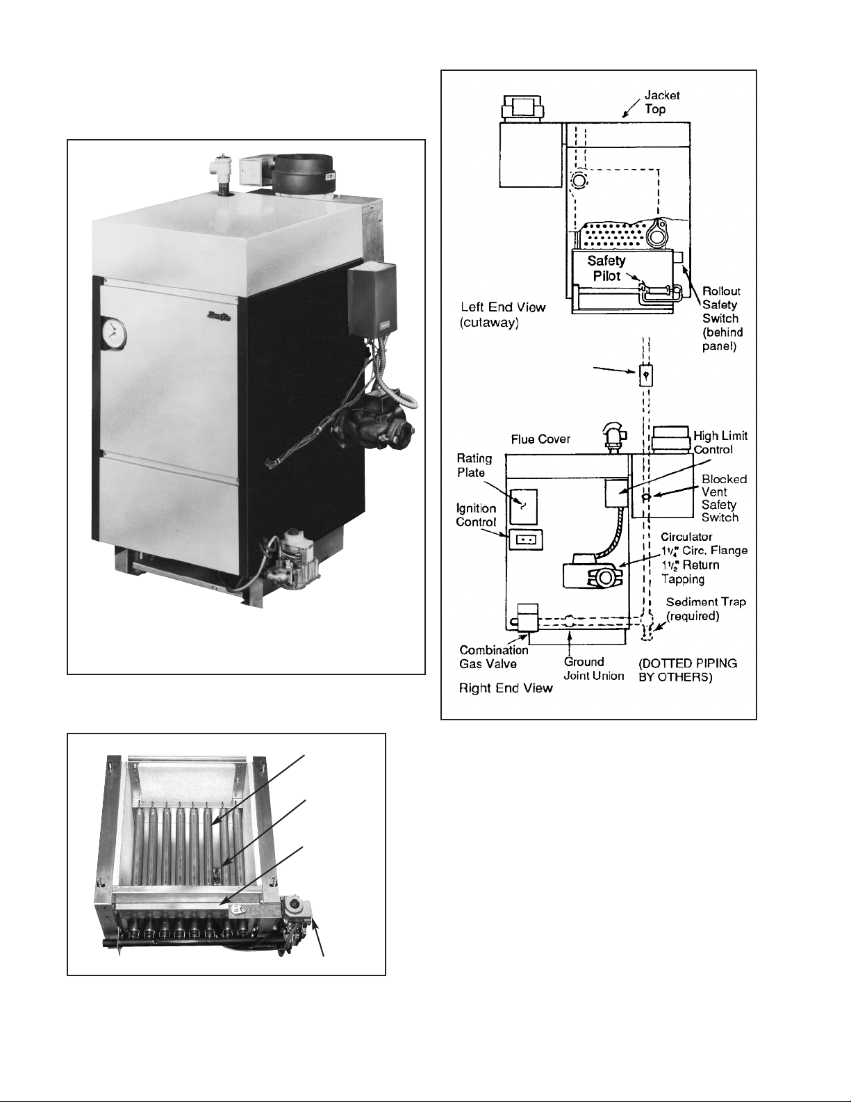
ENTRY SERIES BOILER
S
Location and identification of parts.
Base Assembly
Front and Right End View
(Sentry “S” Series shown)
Burners
Pilot
Burner
Access
Door
Gas Valve
2
Page 3
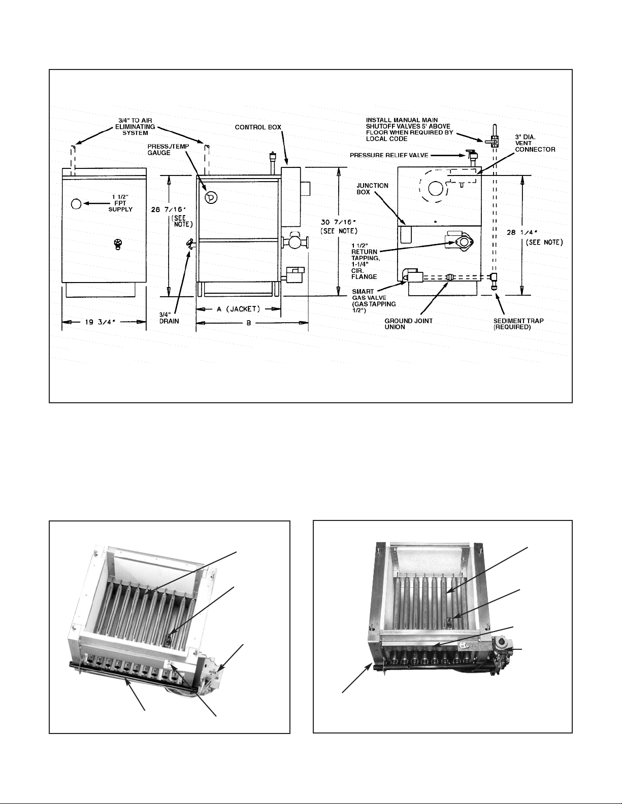
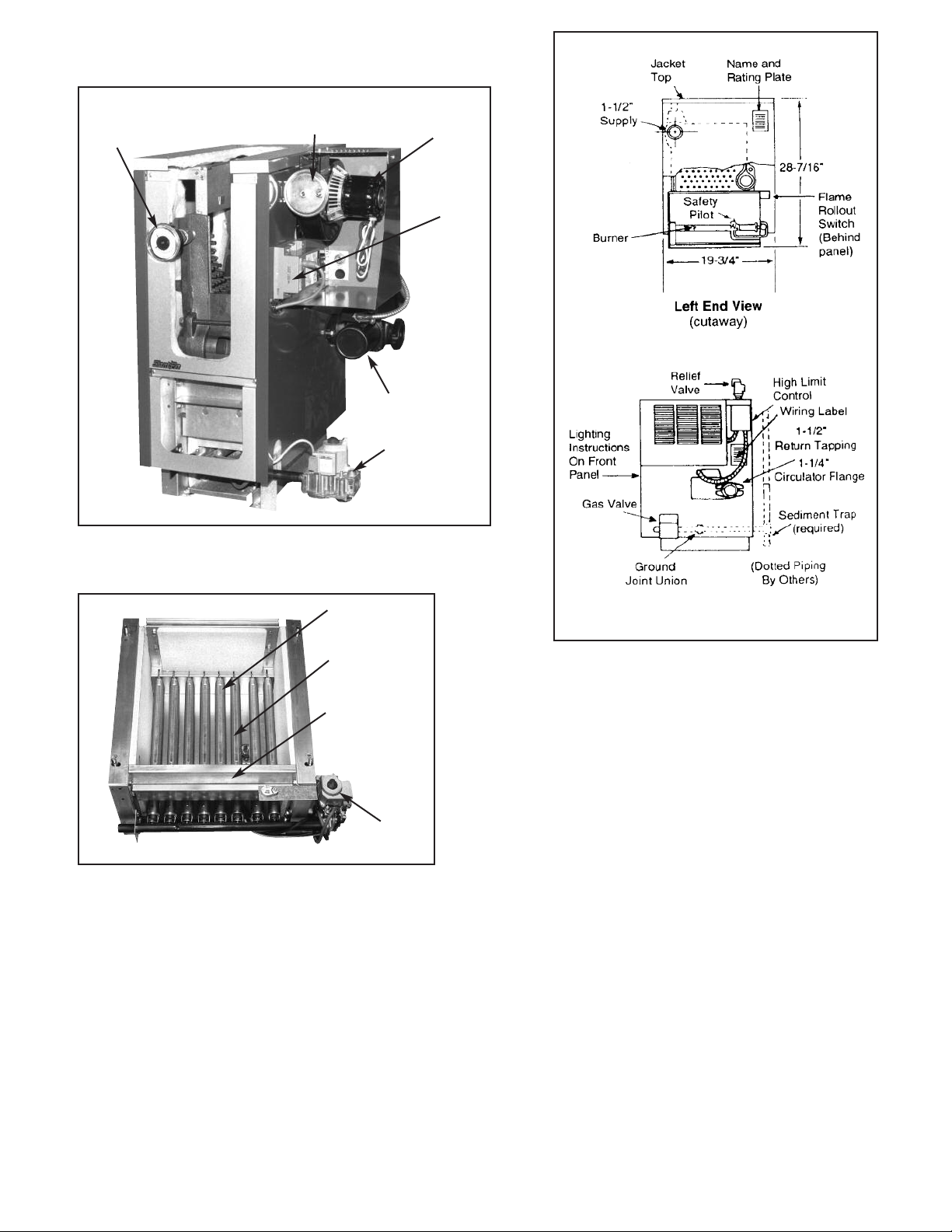
VICTORY VSP AND VSPH SERIES BOILERS
ocation and identification of parts.
L
Base Assembly
3
Page 4
SENTINEL SERIES BOILER
ocation and identification of parts.
L
Burners
Pilot
LEFT END VIEW
Burner
Access
Door
RIGHT END VIEW
Gas Valve
4
Page 5
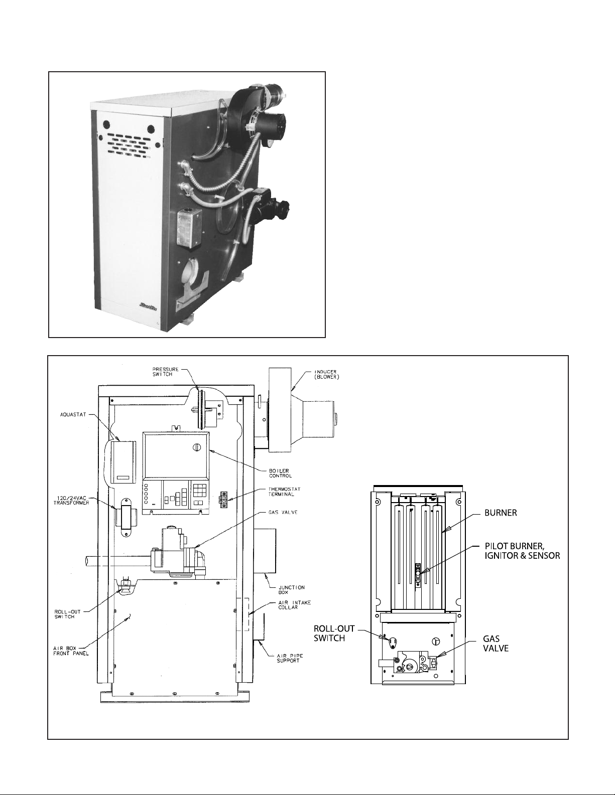
VICTORY II SERIES BOILER
ocation and identification of parts.
L
LEFT END VIEW FRONT VIEW RIGHT END VIEW
VICTORY II - VH, VHL BASE ASSSEMBLY
Location and identification of parts.
Burner
Pilot burner,
ignitor and
sensor
Smart Valve
VICTORY II - VHS, VHLS BASE ASSEMBLY
Location and identification of parts.
Burners
Pilot
Burner
access door
Gas valve
Gas manifold
Roll-out safety
Gas Manifold
switch
5
Page 6
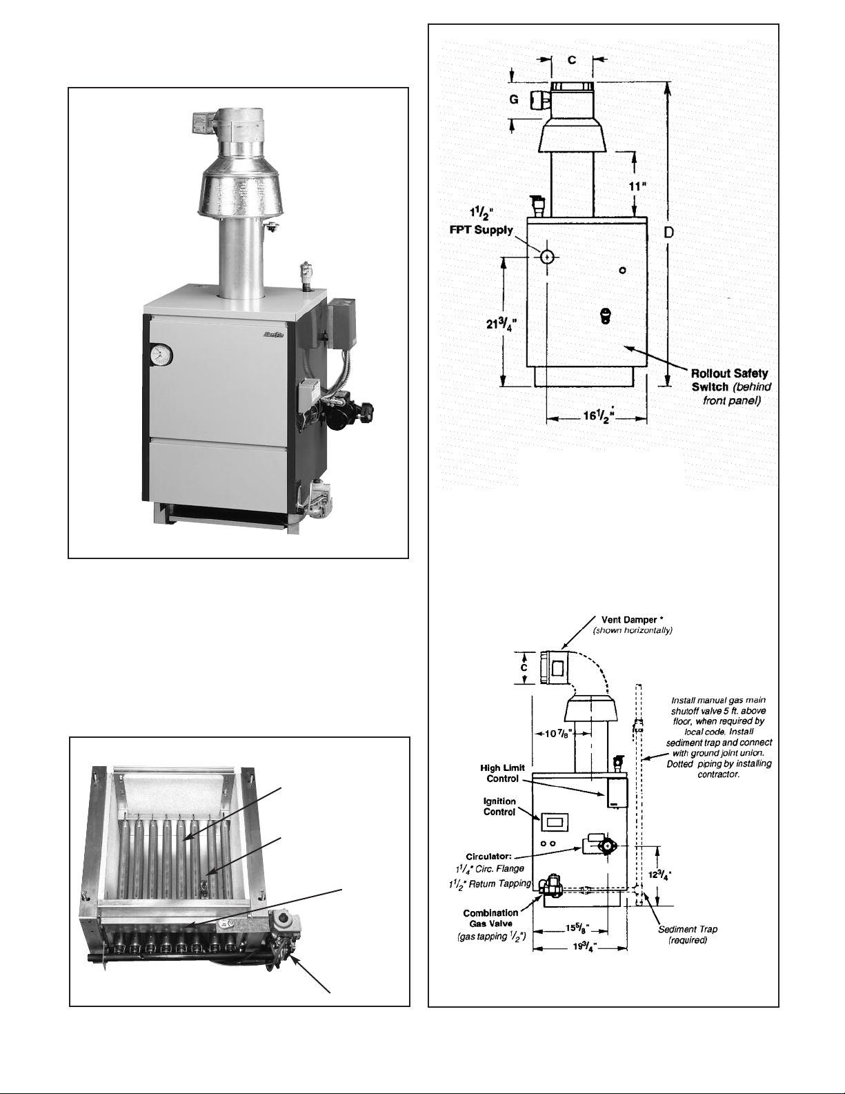
VICTORY V SERIES BOILER
ocation and identification of parts.
L
Pressure/
Temperature
Gauge
Air Flow
Proving Switch
Draft Inducer
Assembly
Ignition
Control
Circulator
Gas Valve
Base Assembly
Burners
Pilot
Burner
Access
Door
Gas Valve
Right End View
6
Page 7

ALAXY BOILER
G
Remove front panel (Figure 1) by pressing hand
against panel and pushing up. Remove burner access
door (Figure 2) by removing 2 wing nuts, slide panel
orward and out.
f
Figure 1. Front Panel
Jacket Top
Name and
Rating Plate
ighting
L
Instructions
(inside front
panel)
as Valve
G
Burner
Access Door
Burners
Relief Valve
emperature
T
and Pressure
Gauge
Gas Manifold
EFORE STARTING
B
heck contents for kit:
C
All components are either marked with a red stripe, a
label with a model number or a stamped number on
them.
1. Honeywell Conversion Kit:
a) Spring: propane = red; natural = stainless steel
b) Regulator adjusting screw
c) Cap screw: propane = black; natural = silver
) Instructions
d
e) Label
2. Main Burner Orifices:
See Table 1 for the correct size orifice as it applies to
this conversion.
3. Pilot Burner Assembly:
a) Pilot burner:
Standing pilot—Honeywell Q314A
Intermittent ignition—Honeywell Q345A
b) Pilot orifice:
Propane—Honeywell BBR-10
Natural—Honeywell BCR-18
4. Ignition Control (for IID only):
Honeywell S8600M (for Sentry, Sentinel or Victory V
series boilers) or S8670E (for Galaxy boilers).
Required for conversion to propane only.
5. Three Labels: Boiler Conversion Label, Affidavit Label
and Gas Valve Label.
6. Registration Card
Caution: The gas supply shall be shut off prior to disconnecting the electrical power, before proceeding with the
conversion.
Figure 2.
Pop Safety Valve
Jacket Top
INSTALLATION
1. Turn Off Gas to Appliance
a) Set thermostat to lowest level.
b) Turn off all electric power to the appliance.
c) Turn the gas control knob clockwise to the off
position.
d) Close all gas cocks.
e) CAUTION: LET BOILER COOL.
f) Remove front jacket panel.
g) Remove burner access door.
2. Gas Valve Conversion
a) Remove pressure regulator cap screw.
b) Remove pressure regulator adjusting screw.
c) Remove regulator spring.
d) Insert appropriate replacement spring (tapered
end down).
Pressure Gauge
Figure 3.
Figure 4. Conversion Kit Installation in Regulator
7
Page 8

) Install new pressure regulator adjustment screw
SHUTTER
BURNER
RETAINER CLIP
M ANIFOLD
MANIFOLD
BURNER
PILOT
e
until it is flush with the top of the casting.
f) After e) above, turn adjustment screw clockwise
as follows:
Propane Gas — 5-
atural Gas — 6 full turns
N
3
⁄4 full turns
g) Install the NEW cap screw.
) Place the gas valve conversion label from the
h
Honeywell kit over the gas valve model number.
3. Pilot Burner Conversion
a) Disconnect pilot line from gas valve.
b) Disconnect flame sensor.
Standing pilot— disconnect thermocouple from
gas valve.
Intermittent ignition — disconnect ignition wire
from S8600 ignition control.
c) BE SURE BURNERS ARE COOL BEFORE
CONTINUING. NOTE LOCATION OF BURNER
WITH PILOT. REMOVE THE BURNER RETAINER
CLIP OF THE PILOT-BURNER. REMOVE THE
BURNER. DISCONNECT THE PILOT TUBE AND
EITHER THE THERMOCOUPLE FOR STANDING
PILOT OR IGNITION WIRE FROM IGNITION
CONTROL. (See figure 6).
d) Remove pilot burner and replace with new pilot
burner.
e) Replace pilot tubing on pilot burner. (It is best to
cut off old ferrule and use new one to ensure a
proper seal.)
f) Replace thermocouple or ignition wire on pilot
assembly.
g) Remove existing main burner orifice from the
manifold and replace with an orifice from the kit.
(See figure 7).
h) Replace the pilot-burner into the boiler. Replace
the burner retainer clip.
4. Orifice Replacement - Remove all other burner
retainer clips and remove the rest of the burners.
a) Remove existing main burner orifices from the
manifold.
b) Install the orifices from the kit. (There may be
more orifices than required.)
c) Reinstall the main burners making sure that the
pilot burner is in the same position as above.
5. Ignition Control Replacement (for IID only)
IMPORTANT
FOR CONVERSION OF BOILERS EQUIPPED
WITH AN INTERMITTENT IGNITION SYSTEM
TO PROPANE, THE IGNITION CONTROL MUST
BE CHANGED. FAILURE TO INSTALL THE CORRECT IGNITION CONTROL COULD CAUSE A
AZARDOUS CONDITION RESULTING IN AN
H
EXPLOSION OR CARBON MONOXIDE POISONING AND WOULD VOID ANY WARRANTY.
a) Remove the S8600F Control from the right side of
the boiler. Note the location of the wires so that
hey may be installed on the proper terminals of
t
the replacement control.
b) Install the NEW S8600M or S8670E control
supplied in the kit. Reconnect the wires, including
the ignition wire. Check applicable wiring diagram
on pages 9 to 15 or the diagram on the boiler to
make certain that the wiring is correct.
6. Registration Card and Labels:
a) Fill out the Boiler Conversion Label, Affidavit Label
and Gas Valve Label. Affix the Boiler Conversion
Label adjacent to the rating plate on the boiler
jacket. Affix the Affidavit Label to the front jacket
panel adjacent to the Slant/Fin logo. Affix the Gas
Valve label on the inside jacket panel above the
gas valve.
b) Fill out the Registration Card. REMEMBER THAT
THIS CARD MUST BE RECEIVED WITHIN 10
DAYS OR THE WARRANTY COULD BE VOIDED.
FINAL CHECKS:
1. Are the burners installed correctly (ports are up)?
2. Is the pilot in the correct position?
3. All of the wiring is correct?
4. All the labels have been filled out and affixed to
the boiler?
5. Has the Registration Card been filled out?
GAS LEAK TESTS
Warning: DO NOT OMIT these tests. Open all gas cocks
upstream of the boiler gas valve. Paint all pipe joints from
the main gas cock to the gas valve with a rich soap and
water solution. Bubbles indicate gas leakage. To stop the
leak, tighten the joints and fittings. DO NOT USE AN
OPEN FLAME FOR TESTING.
Figure 5. Gas Valve — top view
8
Figure 6. Burner/Manifold
Figure 7. Pilot/Burner
Page 9

Wiring Diagram - Victory “V” Series Boilers
CAUTION: Label all wires prior to disconnection when servicing controls.
Wiring errors can cause improper and dangerous operation. “Verify proper
operation after servicing.”
9
Page 10

Wiring Diagrams- Victory II - VH, VHL Series
10
Page 11

Wiring Diagrams- Victory II - VHS, VHLS Series (Spark Ignition)
11
Page 12

Wiring Diagrams- Victory, VSP, VSPH
12
Page 13

WIRING DIAGRAM - GALAXY/SENTRY—CONTINUOUS (STANDING) PILOT
CAUTION: Label all wires prior to disconnection when servicing controls.
Wiring errors can cause improper and dangerous operation. “Verify proper operation after servicing.”
13
Page 14

WIRING DIAGRAM - GALAXY/SENTRY—INTERMITTENT PILOT IGNITION (IID)
CAUTION: Label all wires prior to disconnection when servicing controls.
Wiring errors can cause improper and dangerous operation. “Verify proper operation after servicing.”
14
Page 15

WIRING DIAGRAMS FOR SENTINEL HOT WATER BOILERS
CAUTION: Label all wires prior to disconnection when servicing controls.
Wiring errors can cause improper and dangerous operation. “Verify proper operation after servicing.”
Damper circuit is designed to be controlled by low voltage controls. DO NOT use line voltage operating
Models with Intermittent Pilot Ignition (IID) Models with Continuous Burning Pilot
controls to interrupt supply voltage to the L8148E aquastat.
15
Page 16

SENTRY AND SENTINEL SERIES
Boiler
Model
All Sentinel models and
entry S-34
S
entry S-60 thru
S
S-150 & SX-150 thru
X-210
S
Gas
Type
atural 47 48 48 49 49 49 50 50 51 51
N
Propane 56 56 56 57 57 57 58 59 59 60
Natural 50 51 51 51 51 52 52 52 53 53
ropane 57 58 59 59 60 60 61 62 63 63
P
VICTORY SERIES
Boiler
Model
-33
V
-60 thru V-180
V
SP, VSPH, VH & VHS
V
Gas
Type
Natural 48 49 50 50 50 51 51 52 52 52
ropane 56 56 56 57 57 57 58 59 59 6
P
atural 50 51 51 51 52 52 52 52 53 53
N
Propane 57 58 59 59 60 60 61 62 63 63
atural 49 50 50 50 51 51 51 52 52 52
N
ropane 57 58 59 59 60 60 61 62 63 63
P
Orifice
Size
for
ea
S
Level*
Orifice
Size
for
Sea
Level*
TABLE 1
ORIFICE SIZE TABLE
Orifice Sizes for High Altitudes
Includes 4% Reduction for Each 1000 Feet
levation - Feet
E
2000 3000 4000 5000 6000 7000 8000 9000 10000
Orifice Sizes for High Altitudes
Includes 4% Reduction for Each 1000 Feet
Elevation - Feet
2000 3000 4000 5000 6000 7000 8000 9000 10000
GALAXY SERIES
Orifice
Size
for
Boiler
Model
GG/GX Except Natural 42 43 43 43 43 44 44 45 46 47
GG-399H & GG-350H Propane 54 54 55 55 55 55 55 56 56 56
GG-399H Natural 40 41 42 42 42 43 43 44 44 45
GXH-105 Natural 44 45 45 45 46 47 47 48 48 49
through 275 Propane 54 54 55 55 55 55 55 56 56 56
GXH-300 Natural 43 44 44 44 45 45 46 47 47 48
GXH-300H Natural ** 42 43 43 43 43 44 45 45 46 47
GXHA Natural 45 46 47 47 47 48 48 49 49 50
Gas
Type
Propane 53 54 54 54 54 54 54 55 55 55
Propane 54 54 55 55 55 55 55 56 56 56
Gas Only
Gas Only 55 55 55 55 56 56 56 56 56 57
Sea
Level*
2000 3000 4000 5000 6000 7000 8000 9000 10000
Includes 4% Reduction for Each 1000 Feet
Orifice Sizes for High Altitudes
Elevation - Feet
SENTINEL SERIES
Orifice Sizes for High Altitudes
Includes 4% Reduction for Each 1000 Feet
Elevation - Feet
Boiler
Model
Sentinel
Orifice
Size
for
Gas
Type
Natural 47 48 48 49 49 49 50 50 51 51
Propane 56 56 56 57 57 57 58 59 59 60
Sea
Level*
2000 3000 4000 5000 6000 7000 8000 9000 10000
16
VICTORY II - VHL, VHLS Series (Under 2000 Ft. Only)
Orifice
Boiler
Model
VHL, VHLS
Size
Gas
Type
Natural 49
Propane 57
Sea
Level*
for
* Orifice indicated for sea level above are factory installed in boiler unless
otherwise specified by the local authority.
See page 19 for burner input adjustment.
** For L.P. Propane consult factory.
Page 17

TABLE 2
INPUT RATING OF BOILERS
Note: All models of the boilers will have the same input rating after converted.
17
Page 18

LIGHTING INSTRUCTIONS
Continuous Burning Pilot (24V).
OR BOILERS EQUIPPED WITH GAS VALVES
F
VR8200
and VR8300.
SAFETY INFORMATION
FOR YOUR SAFETY READ BEFORE LIGHTING
WARNING: If you do not follow these instructions
exactly, a fire or explosion may result causing
property damage, personal injury or loss of life.
A. This appliance has a pilot which must be lighted by
hand. When lighting the pilot, follow these instructions exactly.
B. BEFORE LIGHTING smell all around the appliance
area for gas. Be sure to smell next to the floor
because some gas is heavier than air and will settle
on the floor.
WHAT TO DO IF YOU SMELL GAS
• DO NOT try to light any appliance.
• DO NOT touch any electric switch; DO NOT use
any phone in your building.
• Immediately call your gas supplier from a
neighbor's phone. Follow the gas supplier's
instructions.
• If you cannot reach your gas supplier, call
the fire department.
C. Use only your hand to push in or turn the gas control
knob. NEVER use tools. If the knob will not push
in or turn by hand, DON'T try to repair it, call a
qualified service technician. Force or attempted
repair may result in a fire or explosion.
D. DO NOT use this appliance if any part has been
underwater. Immediately call a qualified service
technician to inspect the appliance and to replace
any part of the control system and any gas control
which has been underwater.
Lighting Instructions
1. STOP! Read the safety information above on this
page.
2. Set the thermostat to lowest setting.
3. Turn off all electric power to the appliance.
4. Remove control access panel. (Galaxy models only.)
5. Push in gas control knob slightly and turn clockwise
to "OFF".
6. Wait five (5) minutes (longer for propane) to clear
out any gas. If you then smell gas, STOP! Follow
"B" in the safety information. If you don't
smell gas, go to next step.
. Remove the pilot access panel located
7
below and behind the gas control unit.
8. Find pilot—follow the aluminum tubing from the
gas valve. The pilot is between two burner tubes
behind the burner access panel.
9. Turn knob on gas control counterclockwise to
"PILOT".
10. Push in red button all the way and hold in.
Immediately light the pilot with a match. Continue
to hold the red button in for about one (1) minute
after the pilot is lit. Release knob and it will pop
back up. Pilot should remain lit. If it goes out,
repeat steps 5 through 10.
• If knob does not pop up when released, stop
and immediately call your service technician
or gas supplier.
• If the pilot will not stay lit after several tries,
turn the gas control knob to "OFF" and call
your service technician or gas supplier.
11. Replace pilot access panel.
12. Turn gas control knob counterclockwise to
“ON".
13. Replace control access panel. (Galaxy models
only.)
14. Turn on all electric power to the appliance.
15. Set thermostat to desired settings.
To Turn Off Gas To Appliance
1. Set the thermostat to lowest setting.
2. Turn off all electric power to the appliance if service is to be performed.
3. Remove control access panel. (Galaxy models
only.)
4. Turn gas control knob clockwise to "OFF".
DO NOT force.
5. Replace control access panel. (Galaxy models
only.)
VALVE VR8200
OR VR8300
RED BUTTON
18
GAS CONTROL
KNOB SHOWN IN
“OFF” POSITION.
Page 19

HONEYWELL IID SYSTEM .
FOR BOILERS EQUIPPED WITH GAS VALVE VR8204 OR
VR8304
.
SAFETY INFORMATION
FOR YOUR SAFETY READ BEFORE LIGHTING
ARNING: If you do not follow these instructions exactly,
W
a fire or explosion may result causing property damage,
personal injury or loss of life.
A. This appliance is equipped with an ignition device
hich automatically lights the pilot. DO NOT try to
w
light the pilot by hand.
B. BEFORE OPERATING smell all around the appli-
ance area for gas. Be sure to smell next to the
floor because some gas is heavier than air and will
settle on the floor.
WHAT TO DO IF YOU SMELL GAS
• DO NOT try to light any appliance.
• DO NOT touch any electric switch; DO NOT use
any phone in your building.
• Immediately call your gas supplier from a neighbor's phone. Follow the gas supplier's instructions.
• If you cannot reach your gas supplier, call the
fire department.
C. Use only your hand to push in or turn the gas control
knob. NEVER use tools. If the knob will not push in
or turn by hand, DON'T try to repair it, call a qualified
service technician. Force or attempted repair may
result in a fire or explosion.
D. DO NOT use this appliance if any part has been
underwater. Immediately call a qualified service
technician to inspect the appliance and to replace any
part of the control system and any gas control which
has been underwater.
Lighting Instructions
1. STOP! Read the safety information above.
2. Set the thermostat to lowest setting.
3. Turn off all electric power to the appliance.
4. This appliance is equipped with an ignition device
which automatically lights the pilot. DO NOT try to
light the pilot by hand.
To Turn Off Gas To Appliance
1. Set the thermostat to lowest setting.
2. Turn off all electric power to the appliance if service
s to be performed.
i
3. Remove control access panel. (Galaxy models only.)
4. Turn gas control knob clockwise till knob stops,
then continue to "OFF". DO NOT force.
5. Replace control access panel. (Galaxy models only.)
VALVE VR8204
OR VR8304
BURNER ADJUSTMENT
A. Adjust gas input rate:
1. Consult gas supplier for higher heating value of gas
(Btu/cu.ft.)
2. Set thermostat high enough so that boiler will remain
on while checking rate.
3. Measure manifold pressure at 1/8" tapping. See
label provided with the conversion kit for the correct
manifold pressure for the gas that is being supplied.
NOTE: Gas pressure may be adjusted by turning
pressure regulator screw on combination gas valve
(turn clockwise to increase pressure, counterclock
wise to decrease pressure).
See page 17 for the input rate of your boiler.
a. Input for PROPANE is approximately at rating shown on
rating plate when manifold pressure is 91/2" water
column.
b. Input for NATURAL GAS is approximately at rating
when manifold pressure is 31/2" water column, but
should be checked on the gas meter:
GAS VALVE VR8204
OR VR8304
GAS CONTROL KNOB
SHOWN IN “OFF”
POSITION
5. Remove control access panel. (Galaxy models only.)
6. Turn gas control knob clockwise till knob stops,
continue to "OFF". DO NOT force.
7. Wait five (5) minutes (longer for propane) to clear out
any gas. If you then smell gas, STOP! Follow "B" in
the safety information. If you don't smell gas, go to
next step.
8. Turn gas control knob counterclockwise to "ON".
9. Replace control access panel. (Galaxy models only.)
10. Turn on all electric power to the appliance.
11. Set thermostat to desired setting.
12. If the appliance will not operate, follow the instructions
"To Turn Off Gas To Appliance" and call your service
technician or gas supplier.
Btuh Input = Btu/cu. ft. x cu. ft. metered
in 3 minutes x 20
Example 1
For 1000 Btu/cu.ft. gas, this becomes:
Btuh Input = cu. ft. metered in 3 minutes
Example 2
For 1050 Btu/cu.ft. gas, this becomes:
Btuh Input = cu. ft. metered in 3 minutes
4. The higher* heating value of gas varies substantially
for different localities. Consult with Slant/Fin’s
Technical Service Dept. for re-orificing procedures
if any of the following apply:
a. Boiler (burner) is overfiring. CAUTION! National
Fuel Gas Code ANSI Z223.1-latest edition does
NOT permit firing at a higher input rate than the
input rate indicated on the boiler rating plate in
order to avoid hazardous conditions such as
explosion or carbon monoxide poisoning.
b. Poor higher* heating value of gas is causing the actual
input to be substantially lower than
:
x 1,000 Btu/cu.ft. x 20
:
x 1050 Btu/cu.ft. x 20
the rating plate
indication.
* “Higher heating” value of gas is commonly known as “heating value”.
19
Page 20

GAS RATE TABLE
Cubic Feet
Boiler rated input Gas Consumption
cu. ft./hr. of 1000 Btu/cu. ft. 1000 Btu/cu.ft. gas, in 3
Natural Gas minutes, at rated input
33 1.65
34 1.70
60 3.00
70 3.50
75 3.75
90 4.50
100 5.00
105 5.25
120 6.00
125 6.25
140 7.00
150 7.50
175 8.75
180 9.00
200 10.00
210 10.50
225 11.25
245 12.25
250 12.50
275 13.75
300 15.00
325 16.25
350 17.50
375 18.75
399 19.95
The gas metered in 3 minutes to obtain rated input for each boiler
model using 1000 Btu/cu.ft. gas is tabulated in the gas rate table.
B. Main Burner
1. Fire the boiler continuously for at least 15 minutes,
to reach burner operating temperature.
2. Observe the flames, all burners. The base of all
flame jets should be blue. The tips should be blue
shading to orange.
NOTE: Dust, disturbed by any movement, will
cause bright orange flames. Wait for dust to settle.
3. For one burner, close the air shutter until some of
its flame jet tips turn yellow-white, indicating insufficient primary air. Then open shutter until whitish
tips disappear completely. Set all burner shutters
to the same opening. Observe to make sure that
no yellow-white tips appear over any portion of
the flame. Small yellow tips at the pilot location are
permitted.
NOTE: This adjustment method gives MINIMUM
primary air setting for safe combustion. DO NOT
attempt to make this adjustment unless burners
are at operating temperature. Adjustment should
e made with burner access panel in final operat-
b
ing position. Use of a mirror may be helpful to
observe flames. Note that burner ports are on top
of main burner tube.
C.Main Burner Ignition Checkout and Pilot Adjustment
1. The pilot flame must not smother or snuff out
when tested as follows:
a. Main burner ignition from cold start-repeat.
b. Continued operation of main burner.
c. Main burner ignition with appliance at maxi
mum operating temperature after prolonged
operation.
NOTE: Observe operation of the pilot burner with
appliance doors in the final operating position.
Use of a mirror may be helpful.
Flame Tips
Blue Flame Base
Main Burner
Manifold
Front-back sliding primary air
shutter locking screw on top.
2. Safety Shutdown Checkout
a. For proper operation the pilot should engulf the
thermocouple or flame sensor as shown below.
b. To adjust pilot, turn pilot flow adjustment screw
on valve clockwise or counterclockwise to give
a steady flame enveloping 3/8" to 1/2" inch of
the tip of the thermocouple or flame sensor.
Note that turning the pilot adjustment screw
clockwise will decrease the pilot flame.
Gas Pressure (inches of wc)
Gas Manifold Minimum Inlet Maximum Inlet
Natural Gas 3.5” 5” 11”
LP Propane 9.5” 11” 14”
SLANT/FIN CORPORATION, Greenvale, N.Y. 11548 • Phone: (516) 484-2600
FAX: (516) 484-5921 • Canada: Slant/Fin LTD/LTEE, Mississauga, Ontario
www.slantfin.com
 Loading...