

Page 1

User’s Information Manual
Galaxy GG, GX, GXH & GXHA Series, Sentry S/SX Series
and Sentinel SE Series Gas Boilers with Continuous Pilot
FOR YOUR SAFETY:
• Before operating this boiler, READ this manual.
• DO NOT attempt to install, service or repair this boiler yourself. There are no user serviceable
parts. Contact a qualified service agency if your boiler needs repair or maintenance. Ask your
gas supplier for a list of qualified service agencies.
WARNING: If the information in this
manual is not followed exactly, a fire
or explosion may result causing
property damage, personal injury or
loss of life.
— DO NOT store or use gasoline or
other flammable vapors and liquids in
the vicinity of this or any other appliance.
WHAT TO DO IF YOU SMELL GAS
—
• DO NOT try to light any appliance.
• DO NOT touch any electrical
switch; DO NOT use any phone in
your b
• Immediately call your gas supplier
from a neighbor's phone. Follow
the gas supplier's instructions.
• If you cannot reach your gas
supplier, call the fire department.
uilding.
DO NOT use this boiler if any part has
been underwater. Immediately call a
qualified service technician to inspect
the boiler and to replace any part of the
control system and any gas control
which has been underwater.
WARNING
Should overheating occur or the gas
supply fail to shut off, DO NOT turn off
or disconnect the electric supply to the
circulator pump. Instead, shut off the
gas supply at a location EXTERNAL to
the appliance.
— Installation and service must be
performed by a qualified installer,
service agency or the gas supplier.
If your boiler is purchased with or will be equipped with an automatic vent damper, make certain
that the damper is installed and wired by a qualified installer who has been certified by your local
gas utility. See Vent Dampers page 7.
Keep the boiler area clean and free of all materials that can burn.
Never close or reduce openings that supply air for the boiler combustion and for ventilation.
Your gas boiler must be installed and serviced by a qualified service agency or
gas supplier. The lack of proper service can result in a dangerous condition.
Printed in U.S.A. 1005 PUBLICA
TION NO. GS-UIM-CBP
P
ar
t No.
41-1824
Page 2
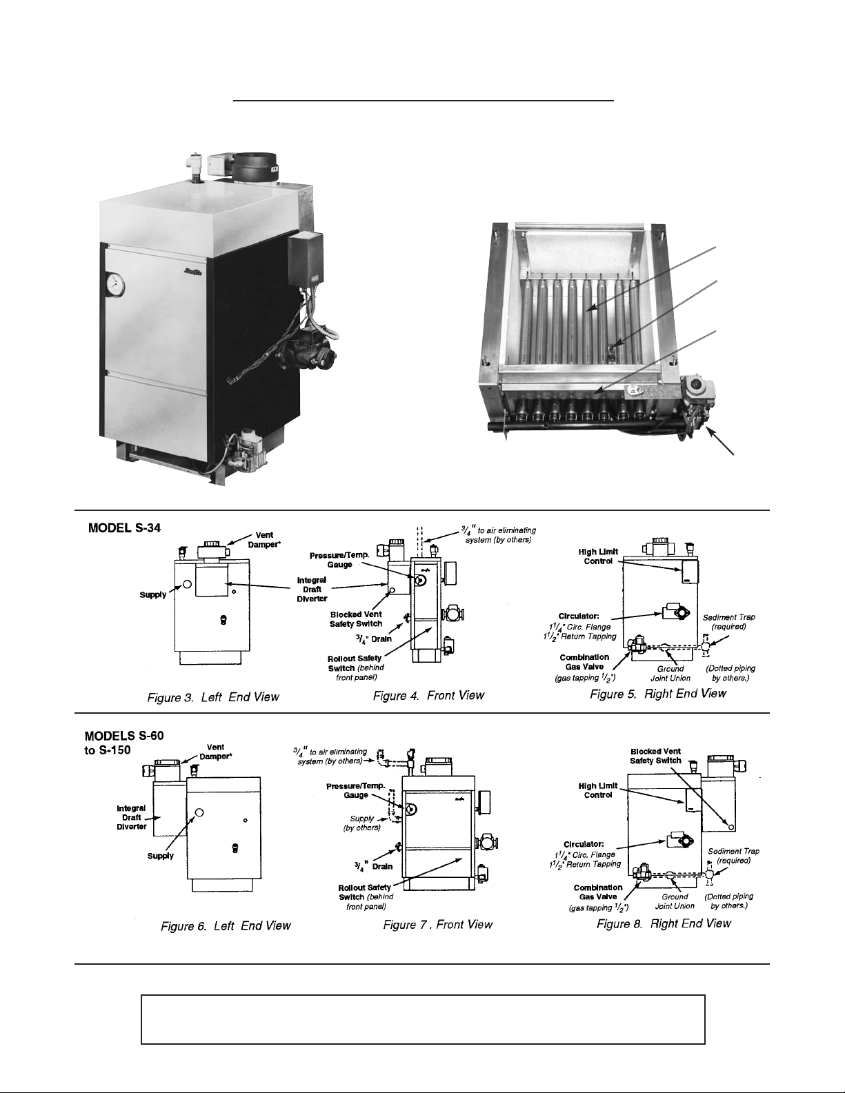
Figure 1.
SENTRY “S” SERIES HOT WATER BOILER
W
ITH INTEGRAL DRAFT DIVERTER
Location and identification of parts
Figure 2.
Burners
Pilot
Burner
Access
Door
Front and Right End View
Models S-60 thru S-150
Base Assembly
Gas Valve
* Vent damper may be installed horizontally on all models with use of a common vent elbow.
See lighting instructions on pages 7-8.
Your gas boiler must be installed and serviced by a qualified service agency or
gas supplier
. The lack of proper service can result in a dangerous condition.
2
Page 3
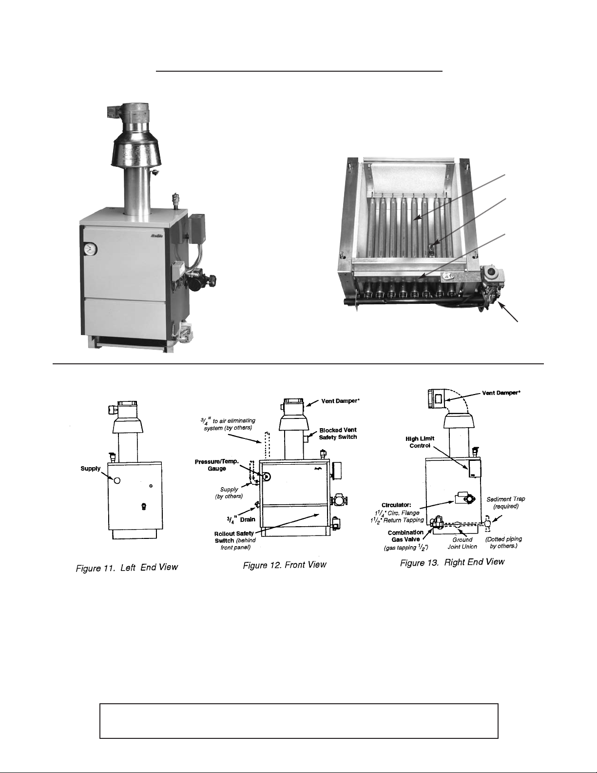
Figure 9.
SENTINEL “SE” SERIES and
SENTRY “SX” SERIES HOT WATER BOILER
W
ITH EXTERNAL DRAFT HOOD
Location and identification of parts
Figure 10.
Burners
Pilot
Burner
Access
Door
Base Assembly
Front and Right End View
MODELS SX-150
to SX-210 and
SE-70 to SE-245
* Vent damper may be installed horizontally on all models with use of a common vent elbow.
Gas Valve
See lighting instructions on pages 7-8.
Your gas boiler must be installed and serviced by a qualified service agency or
gas supplier
. The lack of proper service can result in a dangerous condition.
3
Page 4

igure 14.
F
J
Name and
Rating Plate
Lighting
Instructions
(inside front
p
anel)
Gas Valve
B
urner
Access Door
Burners
Figure 15.
GALAXY GG/GX GXHA SERIES HOT WATER AND STEAM BOILER
L
ocation and identification of parts
Relief Valve
acket Top
Temperature
and Pressure
Gauge
Gas Manifold
Pop Safety Valve
Jacket Top
Figure 16 GXHA Ser
Pop Safety Valve
Jacket Top
Pressure Gauge
ies—Steam Boiler
Pressure Gauge
Figure 17.
Front
Panel
Easy access front panel on standard extended jacket, is removed
by simply pressing hand against panel and pushing up.
See lighting instructions on page 8.
Your gas boiler must be installed and serviced by a qualified service agency or
gas supplier. The lack of proper service can result in a dangerous condition.
4
Page 5

Inspection, cleaning, repair—
Chimney, flue pipe and boiler
Your boiler and heating system will last an indefinitely
long time at full efficiency, if it is inspected regularly
and is kept in good repair and adjustment.You, the user,
should make regular inspections, and report any problems to your service agency. At regular intervals, you
should have that agency inspect the system, and clean
he boiler and make repairs and adjustments as neces-
t
sary. What you and the service agency should do are
listed below.
Contact your gas supplier for a list of qualified service
and repair agencies.
User inspection
At least once each month during the heating season
and once just before cold weather starts:
(1) Look closely at the smokepipe and draft hood (see
Figure 18, 19 & 20). Make sure pipe joints are snug
and are fastened with screws. Cement at the chimney joint should fill the joint and should not leak air.
There should be no visible signs of rust (corrosion)
or salts from water evaporation.
(2) Look at all water (or steam) piping. There should be
no leaks or signs of leaks at any pipe joints or
around the boiler. Drain valves, other valves, and
the relief valve (or steam safety valve) should not
drip or leak.
(3A) On water boilers:
The temperature and pressure gauge indicates the
pressure in the boiler at each water temperature.
For most installations, it should indicate about 12 to
15 psi pressure when temperature is about 70 to
100 degrees F, and from 15 psi to 25 psi when temperature is up to 240 degrees F. FOR YOUR SYSTEM, there is one correct pressure for each temperature
. ASK YOUR INSTALLER OR SERVICEPERSON TO EXPLAIN AND SHOW YOU. Learn what
normal pressures to look for. If pressure decreases
from nor
mal, your system is losing water
. If pres-
ure rises from normal, the relief valve will open to
s
relieve the pressure. Call your service organization
if pressures are higher or lower than normal, and if
he relief valve spills water. Repair or adjustment is
t
eeded.
n
(3B) On steam boilers:
(a) The water level in the gauge glass must be kept
constant. You must have your installer or service
organization explain to you how water is added to
maintain water level.
(b) Most boiler models are equipped with float type low
water cutoff.
You must be familiar with this LOW WATER CUT-
OFF, how it works and HOW TO BLOW IT DOWN.
Instructions are supplied with it. Ask your service
organization to e
The cutoff should be blown down three times the
first week and should be blown down weekly there-
after. Maintenance of the low water cutoff is vital in
protecting your steam boiler against breakage due
to loss of water.
If your boiler is equipped with an electronic probe
type low water cutoff, it requires periodic testing.
Ask your service agency to test this low water cutoff
twice a year.
(4) Study the labels attached to your boiler, especially
the LIGHTING AND SHUTDOWN instructions. Have
your installer or service organization show you how
to start and shut down the boiler following those
instructions. The lighting instructions on your boiler
are also reproduced, with pictures, in this manual.
(5) Stand near the boiler, look and listen. As the burners
start and shut off, there should be no unusual noise.
No fire should be visible coming out of the front
when the burners start or run.
(6) Ample air is required for your boiler to burn fuel
cleanly and safely. Check to make sure the open-
ings provided in your house are not closed and are
not obstructed. This is most important in colder
weather, when most air is needed.
xplain and show you blowdown.
Figure 18. (Galaxy GG, GX, GXH,
Sentinel SE, Sentry SX boilers)
Your gas boiler must be installed and serviced by a qualified service agency or
gas supplier. The lack of proper service can result in a dangerous condition.
Figure 19.
Figure 20.
5
Page 6

(7) If equipped with vent damper, which can ONLY be
installed on boilers equipped with 24 volt gas valve:
(a) Your vent damper must be OPEN when the boiler is
operating (BURNERS ARE ON). Ask your installer
or serviceperson to show you the vent damper position indicator, indicating the open and closed
damper positions. Inspect for proper operation
monthly. If damper position indicator indicates that
the damper is closed when the boiler is operating,
SHUTDOWN the boiler immediately and call your
service agency.
(b) This device must be installed and inspected annually
by a qualified installer in accordance with the
Slant/Fin vent damper installation instructions. If
improperly installed, a hazardous condition such as
explosion or carbon monoxide poisoning could
result. If installed improperly, all vent damper and
boiler warranties shall be voided.
If you find during your inspection any unusual
noise, water leak, corroded smokepipe, abnormal water pressure or flame rollout, call for
service immediately.
SERVICE INSPECTION
The selected service organization should make these
inspections, pref
weather begins:
(1) Make the checks for leaks, corrosion, noise, flame,
heat and outside air supply described under User’s
Inspection.
(2) Check safety operation of the HIGH LIMIT CON-
TR
OL (and, for steam boilers, the LOW WATER
CUT
OFF) and GAS VALVE. If the boiler is equipped
with an automatic vent damper, check this device for
saf
e and automatic operation.
(3) Check gas input rate, by clocking the gas meter.
Inspect burner flame. Clean and adjust burners and
adjust gas rate as required.
(4)
Disconnect flue pipe from draft hood. Remove draft
hood and inspect boiler heating surface below. If any
soot, scale or rust is visible, clean the boiler as
described in the next section.
erably once each year, before the cold
Figure 21.
CLEANING—BOILER, SMOKEPIPE,
CHIMNEY
in (4) of Service Inspection section, the selected service
organization should clean the boiler as follows:
(1) Shut off electric power and gas supply.
(2) Disconnect smokepipe and remove draft hood.
(3) Remove jacket top panel. Remove flue cover
from boiler.
(4) Remove access door and remove burners, or place
cover over burners for dirt protection.
(5) Brush down boiler flues to bare metal. Clean all
debris from bottom of boiler after brushing.
Clean b
(6) Replace flue cover and seal with furnace cement.
Replace burners if removed. Replace access door.
(7) Inspect draft hood and smokepipe. If corroded,
replace. If soot or deposits from condensation are
found, clean out, and inspect inside of chimney for
soot or other deposits. Clean if necessary.
(8) Reconnect hood and flue pipe and fasten and seal
all joints. Turn on gas and electric power.
(See Figure 21). If necessary as indicated
urner slots, if necessary.
(5) Replace any corroded smokepipe. Repair or re-
place other devices as found necessary. Check and
adjust for normal operation. Explain to the user
what was done and what to look for to prevent future problems.
Your gas boiler must be installed and serviced by a qualified service agency or
gas supplier. The lack of proper service can result in a dangerous condition.
(9) Check boiler performance after cleaning, and adjust
as necessary.
NOTE: Condensate (water), rust, scale and soot are not
found in the boiler or smokepipe of normally operating
system. If any of these is found, eliminate the cause.
The most likely cause of condensate and corrosion or
soot is (a) restr
6
icted air supply, or (b) a faulty chimney.
Page 7

VENT DAMPERS
A Slant/Fin vent damper is available only as part of a
Slant/Fin gas boiler package equipped with a 24 volt
gas valve.This vent damper is design certified by A.G.A.
or use only on specific Slant/Fin Corporation gas boiler
f
odels.
m
These boilers will be equipped with a plate which states
that the boiler may be used with a Slant/Fin Corp. automatic vent damper device and indicates the proper vent
damper model number.
OTHER VENT DAMPER OR DEVICES WITH SIMILAR
PURPOSE ARE NOT PERMITTED.
WITH ANY VENT DAMPER
OR PILOT SYSTEM
(a) DO NOT attempt to install or adjust or service it
yourself.
(b) Make certain that the installation is approved by your
local gas utility.
IGNITION SYSTEM—CONTINUOUS
BURNING (STANDING) PILOT
Your gas boiler is equipped with the Honeywell VR8200
or VR8300 gas valves. See Safety and Lighting
Instructions on pages 7 and 8 and Figure 22.
SAFETY AND LIGHTING INSTRUCTIONS
FOR IGNITION SYSTEMS EQUIPPED WITH GAS
VALVES VR8200 AND VR8300
SAFETY INFORMATION
For Your Safety Read Before Lighting
WARNING: If you do not follow these instructions
exactly, a fire or explosion may result causing
property damage, personal injury or loss of life.
A. This appliance has a pilot which must be lighted by
hand. When lighting the pilot, follow these instructions e
xactly.
Figure 22. Continuous (Standing) Pilot
Ignition System
WARNING
Should overheating occur or the gas supply fail to shut off, DO NOT turn
off or disconnect the electric supply to the circulator pump. Instead,
shut off the gas supply at a location EXTERNAL to the appliance.
Your gas boiler must be installed and serviced by a qualified service agency or
gas supplier. The lack of proper service can result in a dangerous condition.
7
Page 8

B. BEFORE OPERATING smell all around the appli-
ance area for gas. Be sure to smell next to the floor
because some gas is heavier than air and will settle
on the floor.
WHAT TO DO IF YOU SMELL GAS
• DO NOT try to light any appliance.
• DO NOT touch any electric switch; DO NOT use
ny phone in your building.
a
• Immediately call your gas supplier from a neigh-
bor’s phone. Follow the gas supplier’s instructions.
• If you cannot reach your gas supplier, call the fire
department.
C. Use only your hand to push in or turn the gas control
knob. NEVER use tools. If the knob will not push in
or turn by hand, DON’T try to repair it, call a qualified service technician. Force or attempted repair
may result in a fire or explosion.
D. DO NOT use this appliance if any part has been
underwater. Immediately call a qualified service
technician to inspect the appliance and to replace
any part of the control system and any gas control
which has been underwater.
LIGHTING INSTRUCTIONS
1. STOP! Read the safety information on page 7 and
above.
2. Set the thermostat to lowest setting.
3. Turn off all electrical power to the appliance.
4. Remove control access panel. (Galaxy models
only.)
5. Turn gas control knob clockwise to “OFF”.
7. Remove the pilot access panel located below and
behind the gas control unit.
8. Find pilot, follow metal tube from
gas control. The pilot is between
two burner tubes behind the pilot
access panel.
9. Turn knob on gas control counterclockwise
to “PILOT”.
10. Push in red button all the way and hold in.
Immediately light the pilot with a match. Continue to
hold the red button in for about one (1) minute after
the pilot is lit. Release button and it will pop back
up. Pilot should remain lit. If it goes out, repeat
steps 5 through 10.
• If button does not pop up when released, stop
and immediately call your service technician or
gas supplier.
• If the pilot will not stay lit after several tries, turn
the gas control knob to “OFF” and call your
service technician or gas supplier.
11. Replace pilot access panel.
12. Turn gas control knob counterclockwise to
“ON”.
13. Replace control access panel. (Galaxy models
only.)
14. Turn on all electric power to the appliance.
15. Set thermostat to desired setting.
TO TURN OFF GAS TO APPLIANCE
1. Set the thermostat to lowest setting.
2. Turn off all electric power to the appliance, if service
is to be performed.
3. Remove control access panel. (Galaxy models
only.)
4. Turn gas control knob clockwise to “OFF”. DO
NOT force.
5. Replace control access panel. (Galaxy models
only
.)
6. Wait five (5) minutes (longer for propane) to clear
out any gas, then smell for gas, including near the
floor. If you then smell gas
safety information above on this page, if you don’t
smell gas, go to next step.
STOP! Follow “B” in the
Your gas boiler must be installed and serviced by a qualified service agency or
gas supplier. The lack of proper service can result in a dangerous condition.
©Slant/Fin Corp. 2004.
SLANT/FIN CORPORATION, Greenvale, N.Y. 11548 • Phone: (516) 484-2600
These boilers are equipped with both a blocked vent
saf
ety switch and a rollout safety s
vent safety switch is located on the draft hood flue stack.
This is a manual reset control used to prevent excessive
spillage of flue gases from the draft hood. The rollout
safety switch is a single use (one time) thermal fuse to
prevent the boiler from operation if flue passages are
b
locked. If either of these devices operate to shut down
the burners, follow instructions in the section “To Turn
Off Gas To Appliance” and call your service technician
or gas supplier.
FAX: (516) 484-5921 • Canada: Slant/Fin LTD/LTEE, Mississauga, Ontario
witch. The blocked
www.slantfin.com
 Loading...